JP6803258B2 - Heat medium heating device and vehicle air conditioner - Google Patents
Heat medium heating device and vehicle air conditioner Download PDFInfo
- Publication number
- JP6803258B2 JP6803258B2 JP2017027930A JP2017027930A JP6803258B2 JP 6803258 B2 JP6803258 B2 JP 6803258B2 JP 2017027930 A JP2017027930 A JP 2017027930A JP 2017027930 A JP2017027930 A JP 2017027930A JP 6803258 B2 JP6803258 B2 JP 6803258B2
- Authority
- JP
- Japan
- Prior art keywords
- heat medium
- terminal
- casing
- ptc heater
- control board
- Prior art date
- Legal status (The legal status is an assumption and is not a legal conclusion. Google has not performed a legal analysis and makes no representation as to the accuracy of the status listed.)
- Active
Links
Images


Classifications
-
- H—ELECTRICITY
- H05—ELECTRIC TECHNIQUES NOT OTHERWISE PROVIDED FOR
- H05B—ELECTRIC HEATING; ELECTRIC LIGHT SOURCES NOT OTHERWISE PROVIDED FOR; CIRCUIT ARRANGEMENTS FOR ELECTRIC LIGHT SOURCES, IN GENERAL
- H05B3/00—Ohmic-resistance heating
- H05B3/20—Heating elements having extended surface area substantially in a two-dimensional plane, e.g. plate-heater
- H05B3/22—Heating elements having extended surface area substantially in a two-dimensional plane, e.g. plate-heater non-flexible
- H05B3/24—Heating elements having extended surface area substantially in a two-dimensional plane, e.g. plate-heater non-flexible heating conductor being self-supporting
-
- B—PERFORMING OPERATIONS; TRANSPORTING
- B60—VEHICLES IN GENERAL
- B60H—ARRANGEMENTS OF HEATING, COOLING, VENTILATING OR OTHER AIR-TREATING DEVICES SPECIALLY ADAPTED FOR PASSENGER OR GOODS SPACES OF VEHICLES
- B60H1/00—Heating, cooling or ventilating [HVAC] devices
- B60H1/22—Heating, cooling or ventilating [HVAC] devices the heat being derived otherwise than from the propulsion plant
- B60H1/2215—Heating, cooling or ventilating [HVAC] devices the heat being derived otherwise than from the propulsion plant the heat being derived from electric heaters
- B60H1/2218—Heating, cooling or ventilating [HVAC] devices the heat being derived otherwise than from the propulsion plant the heat being derived from electric heaters controlling the operation of electric heaters
-
- B—PERFORMING OPERATIONS; TRANSPORTING
- B60—VEHICLES IN GENERAL
- B60H—ARRANGEMENTS OF HEATING, COOLING, VENTILATING OR OTHER AIR-TREATING DEVICES SPECIALLY ADAPTED FOR PASSENGER OR GOODS SPACES OF VEHICLES
- B60H1/00—Heating, cooling or ventilating [HVAC] devices
- B60H1/22—Heating, cooling or ventilating [HVAC] devices the heat being derived otherwise than from the propulsion plant
- B60H1/2215—Heating, cooling or ventilating [HVAC] devices the heat being derived otherwise than from the propulsion plant the heat being derived from electric heaters
- B60H1/2221—Heating, cooling or ventilating [HVAC] devices the heat being derived otherwise than from the propulsion plant the heat being derived from electric heaters arrangements of electric heaters for heating an intermediate liquid
-
- B—PERFORMING OPERATIONS; TRANSPORTING
- B60—VEHICLES IN GENERAL
- B60H—ARRANGEMENTS OF HEATING, COOLING, VENTILATING OR OTHER AIR-TREATING DEVICES SPECIALLY ADAPTED FOR PASSENGER OR GOODS SPACES OF VEHICLES
- B60H1/00—Heating, cooling or ventilating [HVAC] devices
- B60H1/22—Heating, cooling or ventilating [HVAC] devices the heat being derived otherwise than from the propulsion plant
- B60H1/2215—Heating, cooling or ventilating [HVAC] devices the heat being derived otherwise than from the propulsion plant the heat being derived from electric heaters
- B60H1/2225—Heating, cooling or ventilating [HVAC] devices the heat being derived otherwise than from the propulsion plant the heat being derived from electric heaters arrangements of electric heaters for heating air
-
- F—MECHANICAL ENGINEERING; LIGHTING; HEATING; WEAPONS; BLASTING
- F24—HEATING; RANGES; VENTILATING
- F24H—FLUID HEATERS, e.g. WATER OR AIR HEATERS, HAVING HEAT-GENERATING MEANS, e.g. HEAT PUMPS, IN GENERAL
- F24H1/00—Water heaters, e.g. boilers, continuous-flow heaters or water-storage heaters
- F24H1/10—Continuous-flow heaters, i.e. heaters in which heat is generated only while the water is flowing, e.g. with direct contact of the water with the heating medium
-
- H—ELECTRICITY
- H05—ELECTRIC TECHNIQUES NOT OTHERWISE PROVIDED FOR
- H05B—ELECTRIC HEATING; ELECTRIC LIGHT SOURCES NOT OTHERWISE PROVIDED FOR; CIRCUIT ARRANGEMENTS FOR ELECTRIC LIGHT SOURCES, IN GENERAL
- H05B1/00—Details of electric heating devices
- H05B1/02—Automatic switching arrangements specially adapted to apparatus ; Control of heating devices
- H05B1/0227—Applications
- H05B1/023—Industrial applications
- H05B1/0236—Industrial applications for vehicles
-
- H—ELECTRICITY
- H05—ELECTRIC TECHNIQUES NOT OTHERWISE PROVIDED FOR
- H05B—ELECTRIC HEATING; ELECTRIC LIGHT SOURCES NOT OTHERWISE PROVIDED FOR; CIRCUIT ARRANGEMENTS FOR ELECTRIC LIGHT SOURCES, IN GENERAL
- H05B2203/00—Aspects relating to Ohmic resistive heating covered by group H05B3/00
- H05B2203/02—Heaters using heating elements having a positive temperature coefficient
-
- H—ELECTRICITY
- H05—ELECTRIC TECHNIQUES NOT OTHERWISE PROVIDED FOR
- H05B—ELECTRIC HEATING; ELECTRIC LIGHT SOURCES NOT OTHERWISE PROVIDED FOR; CIRCUIT ARRANGEMENTS FOR ELECTRIC LIGHT SOURCES, IN GENERAL
- H05B2203/00—Aspects relating to Ohmic resistive heating covered by group H05B3/00
- H05B2203/022—Heaters specially adapted for heating gaseous material
- H05B2203/023—Heaters of the type used for electrically heating the air blown in a vehicle compartment by the vehicle heating system
Description
本発明は、熱媒体加熱装置、及び該熱媒体加熱装置を備えた車両用空調装置に関する。 The present invention relates to a heat medium heating device and a vehicle air conditioner provided with the heat medium heating device.
従来の車両用空調装置を構成する熱媒体加熱装置には、PTC(Positive Temperature Coefficient)素子を発熱要素とするPTCヒータを備えたものがある。 Some heat medium heating devices that constitute a conventional vehicle air conditioner include a PTC heater that uses a PTC (Positive Temperature Coefficient) element as a heat generating element.
特許文献1には、PTCヒータと、制御基板と、PTCヒータ及び制御基板を積層した状態で収容するケーシングと、を有する熱媒体加熱装置が開示されている。
PCTヒータは、PTC素子と、PTCヒータ及び制御基板の積層方向に延在する端子を含み、PTC素子の両面に設けられた一対の電極板と、を有する。
制御基板は、一対の電極板の端子がねじ止めされることで、一対の電極板と電気的に接続されている。制御基板は、PTCヒータへの通電を制御する。
Patent Document 1 discloses a heat medium heating device including a PTC heater, a control substrate, and a casing that accommodates the PTC heater and the control substrate in a laminated state.
The PCT heater includes a PTC element, a PTC heater, and a pair of electrode plates provided on both sides of the PTC element, including terminals extending in the stacking direction of the control substrate.
The control board is electrically connected to the pair of electrode plates by screwing the terminals of the pair of electrode plates. The control board controls the energization of the PTC heater.
特許文献1には、PTCヒータ及び制御基板の積層方向に対して直交する直交方向から一対の電極板の端子を制御基板にねじ止めするために、ケーシングの側壁に作業用の窓を設けることが開示されている。 In Patent Document 1, a working window is provided on the side wall of the casing in order to screw the terminals of the pair of electrode plates to the control board from the direction orthogonal to the stacking direction of the PTC heater and the control board. It is disclosed.
しかしながら、特許文献1に開示された熱媒体加熱装置のように、作業用の窓を通じてケーシングの側方からねじ止めの作業を行う場合、ねじ止め作業がやりづらく、作業効率が低下する可能性があった。 However, when the screwing work is performed from the side of the casing through the work window as in the heat medium heating device disclosed in Patent Document 1, the screwing work may be difficult to perform and the work efficiency may decrease. there were.
そこで、本発明は、電極板の端子を制御基板にねじ止めする際の作業効率を高めることの可能な熱媒体加熱装置、及び車両用空調装置を提供することを目的とする。 Therefore, an object of the present invention is to provide a heat medium heating device capable of improving work efficiency when screwing terminals of an electrode plate to a control substrate, and an air conditioner for a vehicle.
上記課題を解決するため、本発明の一態様に係る熱媒体加熱装置は、第1の面、及び第2の面を含むPTC素子、該PTC素子の前記第1の面に設けられ、第1の端子を含む第1の電極板、及び前記PTC素子の前記第2の面に設けられ、第2の端子を含む第2の電極板を有するPTCヒータと、前記第1の端子が接続される第1の接続部、及び前記第2の端子が接続される第2の接続部を含む制御基板と、前記PTC素子の第1の面側に配置され、熱媒体が流れる第1の熱媒体流路を含む第1のケーシング部、及び前記PTC素子の第2の面側に配置され、熱媒体が流れる第2の熱媒体流路を含み、前記第1のケーシング部から取り外し可能な第2のケーシング部を有しており、前記PTCヒータと前記制御基板とを積層させた状態で収容するケーシングと、前記第1の端子の先端部を前記第1の接続部に固定する第1のねじと、前記第2の端子の先端部を前記第2の接続部に固定する第2のねじと、前記PTCヒータの外周面を囲み、かつ前記ケーシングの内面と接触する絶縁部材と、を備え、前記第1の端子の先端部と前記第1の接続部とは、前記PTCヒータ及び前記制御基板の積層方向で対向配置されており、前記第2の端子の先端部と前記第2の接続部とは、前記PTCヒータ及び前記制御基板の積層方向で対向配置されており、前記絶縁部材は、前記第1の端子が挿入される第1の開口部を含む第1のガイド部と、前記第2の端子が挿入される第2の開口部を含む第2のガイド部と、を有し、前記第1及び第2の開口部は、前記PTCヒータ及び前記制御基板の積層方向に延在する。 In order to solve the above problems, the heat medium heating device according to one aspect of the present invention is provided on the first surface, the PTC element including the second surface, and the first surface of the PTC element. The first terminal is connected to a PTC heater having a first electrode plate including the terminal and a second electrode plate provided on the second surface of the PTC element and including the second terminal. A control board including a first connecting portion and a second connecting portion to which the second terminal is connected, and a first heat medium flow arranged on the first surface side of the PTC element and through which a heat medium flows. A second casing portion including a path, a second heat medium flow path arranged on the second surface side of the PTC element and through which a heat medium flows, and removable from the first casing portion. A casing that has a casing portion and accommodates the PTC heater and the control board in a laminated state, and a first screw that fixes the tip end portion of the first terminal to the first connection portion. A second screw for fixing the tip end portion of the second terminal to the second connection portion , and an insulating member that surrounds the outer peripheral surface of the PTC heater and is in contact with the inner surface of the casing. The tip of the first terminal and the first connection are arranged so as to face each other in the stacking direction of the PTC heater and the control board, and the tip of the second terminal and the second connection Are arranged so as to face each other in the stacking direction of the PTC heater and the control board, and the insulating member includes a first guide portion including a first opening into which the first terminal is inserted, and the second guide portion. It has a second guide portion including a second opening into which the terminal is inserted, and the first and second openings extend in the stacking direction of the PTC heater and the control board.
本発明によれば、第1のケーシング部と、第1のケーシング部から取り外し可能な第2のケーシング部と、第1の端子の先端部を第1の接続部に固定する第1のねじと、第2の端子の先端部を第2の接続部に固定する第2のねじと、を備え、PTCヒータ及び制御基板の積層方向で第1の端子の先端部と第1の接続部とを対向配置させるとともに、PTCヒータ及び制御基板の積層方向で第2の端子の先端部と第2の接続部とを対向配置させることで、第1のケーシング部から第2のケーシング部を取り外した状態で、PTCヒータ及び制御基板の積層方向から第1及び第2のねじを螺合することが可能となる。
これにより、ケーシングの側壁に作業用の窓を設ける必要がなくなるとともに、ケーシングの側壁側から作業用の窓を通じてねじ止めする場合と比較して、第1及び第2のねじを第1及び第2の接続部にねじ止めする際の作業効率を高めることができる。
According to the present invention, a first casing portion, a second casing portion that can be removed from the first casing portion, and a first screw that fixes the tip end portion of the first terminal to the first connection portion. , A second screw for fixing the tip of the second terminal to the second connecting portion, and the tip of the first terminal and the first connecting portion in the stacking direction of the PTC heater and the control board. A state in which the second casing portion is removed from the first casing portion by arranging them facing each other and arranging the tip end portion of the second terminal and the second connecting portion facing each other in the stacking direction of the PTC heater and the control board. Then, it becomes possible to screw the first and second screws from the stacking direction of the PTC heater and the control substrate.
As a result, it is not necessary to provide a working window on the side wall of the casing, and the first and second screws are screwed from the side wall side of the casing through the working window as compared with the case where the first and second screws are screwed. It is possible to improve the work efficiency when screwing to the connection part of.
また、上記構成とすることで、第1及び第2の接続部と第1及び第2の端子との位置関係を確認しながら、第1及び第2のねじを螺合することができる。
また、上記構成とされた絶縁部材を有することで、PTCヒータの側面の周囲に配置された導体とPTCヒータの側面との間を絶縁することができるとともに、制御基板に対するPTCヒータの位置決めを行うことができる。
さらに、上記構成とされた第1及び第2のガイド部を有することで、第1及び第2の端子の周囲に配置された導体と第1及び第2の端子との間を絶縁することができる。
Further, with the above configuration, the first and second screws can be screwed while checking the positional relationship between the first and second connecting portions and the first and second terminals.
Further, by having the insulating member having the above configuration, it is possible to insulate between the conductor arranged around the side surface of the PTC heater and the side surface of the PTC heater, and to position the PTC heater with respect to the control board. be able to.
Further, by having the first and second guide portions having the above configuration, it is possible to insulate between the conductors arranged around the first and second terminals and the first and second terminals. it can.
また、上記本発明の一態様に係る熱媒体加熱装置において、前記第1及び第2の端子は、少なくとも2つの折り曲げ部を有してもよい。 Further, in the heat medium heating device according to one aspect of the present invention, the first and second terminals may have at least two bent portions.
このように、第1及び第2の端子が少なくとも2つの折り曲げ部を有することで、第1の端子の先端部と第1の接続部とをPTCヒータ及び制御基板の積層方向で対向配置させることが可能になるとともに、第2の端子の先端部と第2の接続部とをPTCヒータ及び制御基板の積層方向で対向配置させることが可能となる。
これにより、第1のケーシング部から第2のケーシング部を取り外した状態で、PTCヒータ及び制御基板の積層方向から工具を用いて、第1の端子の先端部を第1の接続部に対してねじ止めすることができるとともに、第2の端子の先端部を第2の接続部に対してねじ止めすることができる。
In this way, since the first and second terminals have at least two bent portions, the tip end portion of the first terminal and the first connecting portion are arranged so as to face each other in the stacking direction of the PTC heater and the control board. At the same time, the tip end portion of the second terminal and the second connection portion can be arranged so as to face each other in the stacking direction of the PTC heater and the control board.
As a result, with the second casing portion removed from the first casing portion, the tip portion of the first terminal is attached to the first connection portion by using a tool from the stacking direction of the PTC heater and the control board. It can be screwed, and the tip of the second terminal can be screwed to the second connecting portion.
また、上記本発明の一態様に係る熱媒体加熱装置において、前記第1及び第2の熱媒体流路には、前記ケーシング内に導入された熱媒体が分岐して流れてもよい。 Further, in the heat medium heating device according to one aspect of the present invention, the heat medium introduced into the casing may branch and flow through the first and second heat medium flow paths.
このように、ケーシング内に導入された熱媒体が分岐して第1及び第2の熱媒体流路に流れるように構成してもよい。 In this way, the heat medium introduced into the casing may be branched and flow into the first and second heat medium flow paths.
本発明の一態様に係る車両用空調装置は、上記熱媒体加熱装置と、外気または車室内の空気を循環させるブロアと、前記ブロアの下流側に設けられ、前記外気または前記空気を冷却する冷却器と、前記冷却器の下流側に設けられ、前記PTCヒータにより加熱された前記熱媒体が循環される放熱器と、を備えてもよい。 The vehicle air conditioner according to one aspect of the present invention includes the heat medium heating device, a blower that circulates outside air or air in the vehicle interior, and cooling provided on the downstream side of the blower to cool the outside air or the air. A device and a radiator provided on the downstream side of the cooler and in which the heat medium heated by the PTC heater is circulated may be provided.
このように、車両用空調装置が熱媒体加熱装置を含むことで、第1及び第2の端子を制御基板にねじ止めする際の作業効率を高めることができる。 As described above, since the vehicle air conditioner includes the heat medium heating device, it is possible to improve the work efficiency when screwing the first and second terminals to the control board.
本発明によれば、電極板の端子を制御基板にねじ止めする際の作業効率を高めることができる。 According to the present invention, it is possible to improve work efficiency when screwing the terminals of the electrode plate to the control board.
(実施形態)
図1を参照して、本実施形態に係る車両用空調装置10について説明する。図1に示す矢印は、外気または車室内の空気の流れ方向を示している。
車両用空調装置10は、例えば、ハイブリッド車両や電動車両等に適用可能な空調装置である。
(Embodiment)
The
The
図1を参照するに、車両用空調装置10は、ハウジング11と、ブロア13と、冷却器15と、熱媒体循環回路19を構成する放熱器16と、エアミックスダンパ17と、熱媒体加熱装置25を含む熱媒体循環回路19と、を有する。
With reference to FIG. 1, the
ハウジング11は、取り込み口11Aと、吐出口11Bと、流路11Cと、とされている。取り込み口11Aは、外気または車室内の空気(以下、単に「空気」という)を流路11C内に取り込むための開口部である。吐出口11Bは、流路11Cを通過した空気を車室内に設けられた複数の吹き出し口と接続されている。流路11Cは、空気が流れる経路であり、ハウジング11内に区画されている。
The
ブロア13は、ハウジング11内の取り込み口11A付近に設けられている。ブロア13は、取り込み口11Aから空気を吸い込み、吸い込んだ空気をブロア13の下流側に圧送する。
The
冷却器15は、ブロア13の下流側に位置するハウジング11内に設けられている。冷却器15は、流路11Cの一部を塞ぐように配置されている。冷却器15は、図示していない圧縮機、凝縮器、及び膨張弁とともに冷媒回路を構成する。冷却器15は、膨張弁で断熱膨張された冷媒を蒸発させることで、冷却器15を通過する空気を冷却し、冷却した空気を冷却器15の下流側に供給する。
The
放熱器16は、循環ライン21、タンク23、ポンプ24、エンジン(図示せず)、及び熱媒体加熱装置25とともに熱媒体循環回路19を構成している。放熱器16は、冷却器15の下流側に位置する流路11Cに設けられている。
The
放熱器16は、循環ライン21と接続された導入口16A及び導出口16Bを有する。導入口16Aには、循環ライン21により熱媒体加熱装置25を経由した熱媒体が導入される。放熱器16内を通過した熱媒体は、導出口16Bから循環ライン21に導出される。
放熱器16は、冷却器15から冷却された空気と熱媒体とを熱交換させることで空気を加熱し、加熱した空気を下流側に供給する。
The
The
エアミックスダンパ17は、冷却器15と放熱器16との間に位置する流路11Cに設けられている。エアミックスダンパ17は、放熱器16を通過した空気の量と放熱器16をバイパスして流れる空気の量との割合を調整するためのダンパである。エアミックスダンパ17は、エアミックスダンパ17の下流でミックスされる空気の温度を調節する機能を有する。
The
熱媒体循環回路19は、放熱器16、循環ライン21、タンク23、ポンプ24、エンジン(図示せず)、及び熱媒体加熱装置25を含んだ構成とされている。
熱媒体循環回路19は、例えば、ハイブリッド運転時等、熱媒体であるエンジン冷却水の温度がさほど上昇しない時に、熱媒体加熱装置10によってエンジン冷却水を加熱する。そして、加熱したエンジン冷却水をポンプ24により循環ライン21により循環させることで、ハウジング11内にて放熱器16を通過する空気を加温する。
The heat
The heat
循環ライン21は、ハウジング11の外側に配置されている。循環ライン21は、放熱器16、タンク23、ポンプ24、エンジン(図示せず)、及び熱媒体加熱装置25を接続している。循環ライン21は、熱媒体を循環させるためのラインである。
The
ハイブリッド車両に車両用空調装置10を適用する場合、上記熱媒体としては、例えば、ハイブリッド車両のエンジン冷却水を用いることが可能である。また、エンジンを備えない電動車両に車両用空調装置10を適用する場合、上記熱媒体としては、例えば、ブライン等を用いることが可能である。
When the
タンク23は、導出口16B側に位置する循環ライン21に設けられている。タンク23内には、熱媒体が貯留されている。
The
ポンプ24は、タンク23の下流側に位置する循環ライン21に設けられている。ポンプ24は、タンク23内の熱媒体を熱媒体加熱装置25に供給する。
The
熱媒体加熱装置25は、ポンプ24と放熱器16との間に位置する循環ライン21に設けられている。
The heat
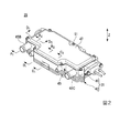
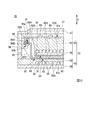
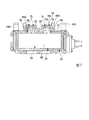
図2〜図8を参照して、熱媒体加熱装置25の構成について説明する。図2〜図5に示すZ方向は、PTCヒータ32及び制御基板37の積層方向を示している。図2〜図8において、同一構成部分には同一符号を付す。図4に示す矢印は、熱媒体が2つに分岐して流れる状態を示している。また、図7では、第1のケーシング部41から第2のケーシング部42を取り外した状態を示している。図8では、熱媒体加熱装置のうち、下部のみを断面図で示す。
The configuration of the heat
熱媒体加熱装置25は、ケーシング31と、PTCヒータ32と、絶縁部材34と、制御基板37と、第1のねじ38と、第2のねじ39と、を有する。
ケーシング31は、第1のケーシング部41と、第2のケーシング部42と、を有する。第1のケーシング部41と第2のケーシング部42とは、分離可能な構成(一方から他方を取り外し可能な構成)とされている。
The heat
The
第1のケーシング部41は、PTCヒータ32を構成するPTC素子61の第1の面61a側に配置されている。第1のケーシング部41は、第2のケーシング部42に対してねじ等により固定されている。第1のケーシング部41は、基板収容部45と、流路形成部46と、蓋部47と、を有する。
The
基板収容部45は、流路形成部46と蓋部47との間に設けられている。基板収容部45は、基板収容凹部45Aと、熱媒体導入口45Bと、熱媒体導出口45Cと、を有する。基板収容凹部45Aは、制御基板37を収容する凹部である。
熱媒体導入口45Bは、熱媒体を循環する循環ライン21と接続されている。熱媒体導入口45Bは、ケーシング31内に形成された第1及び第2の熱媒体流路48,56に熱媒体を導入する。
熱媒体導出口45Cは、循環ライン21と接続されている。熱媒体導出口45Cは、ケーシング31内に設けられた第1及び第2の熱媒体流路48,56を通過した熱媒体を循環ライン21に導出させる。
The
The heat
The
流路形成部46は、板状の部材であり、基板収容部45と対向する部分に複数のフィン46Aを有する。複数のフィン46Aは、基板収容部45に向かう方向に突出している。
流路形成部46と基板収容部45との間には、第1の熱媒体流路48が区画されている。第1の熱媒体流路48は、複数の平行な流路である。第1の熱媒体流路48は、熱媒体導入口45B及び熱媒体導出口45Cと連通している。第1の熱媒体流路48は、PTCヒータ32の一方の面と対向するように配置されている。
The flow
A first heat
蓋部47は、基板収容部45に対して分離可能な構成とされている。蓋部47は、ねじ51で固定されている。蓋部47は、制御基板37と対向している。
The
第2のケーシング部42は、PTC素子61の第2の面61b側に配置されている。第2のケーシング部42は、流路形成部53と、蓋部54と、を有する。
流路形成部53は、板状の部材であり、流路形成部46と蓋部54との間に設けられている。流路形成部53は、蓋部54と対向する部分に複数のフィン53Aを有する。複数のフィン53Aは、蓋部54に向かう方向に突出している。
The
The flow
複数のフィン53Aと蓋部54との間には、第2の熱媒体流路56が区画されている。第2の熱媒体流路56は、複数の平行な流路であり、熱媒体導入口45B及び熱媒体導出口45Cと連通している。第2の熱媒体流路56は、PTCヒータ32の他方の面と対向するように配置されている。
流路形成部46と流路形成部53との間には、PTCヒータ32、圧縮性シート(図3〜図7では図示せず)、及び絶縁部材34(図4及び図5では図示せず)が収容される空間57が形成されている。
図8に示すように、PTCヒータ32の両面は、シリコンシート等からなる圧縮性熱伝達シート64で覆われている。また、PTCヒータ32の周縁部には、絶縁部材34が設けられている。
A second heat
Between the flow
As shown in FIG. 8, both sides of the
PTCヒータ32は、空間57に配置されている。PTCヒータ32は、PTC素子61と、第1の電極板62と、第2の電極板63と、を有する。
The
PTC素子61は、矩形の板状とされた素子であり、第1の電極板62と第2の電極板63との間に配置されている。PTC素子61は、第1の面61aと、第2の面61bと、有する。第1の面61aは、Z方向において第1のケーシング部41に設けられた第1の熱媒体流路48と対向している。
第2の面61bは、第1の面61aの反対側に配置された面である。第2の面61bは、Z方向において第2のケーシング部42に設けられた第2の熱媒体流路56と対向している。
なお、図5及び図6では、1つのPTC素子61のみを図示したが、第1の電極板62と第2の電極板63との間に、複数のPTC素子61を設けてもよい。
The
The
Although only one
第1の電極板62は、3つに分割された第1の電極本体65と、3つの第1の端子66と、を有する。第1の電極本体65は、矩形とされた板状の電極である。第1の電極本体65は、PTC素子61の第1の面61aに設けられている。
第1の端子66は、3つに分割された第1の電極本体65に対してそれぞれ設けられている。3つの第1の端子66のうち、2つの端子は、隣り合うように配置されており、残りの1つの端子は、他の2つの端子から離間した位置に設けられている。
3つの第1の端子66は、第1の電極本体65の端からPTC素子61の外側で、かつ制御基板37に向かう方向に延出している。3つの第1の端子66は、板材が2カ所で折り曲げられた形状とされている。
The
The
The three
3つの第1の端子66は、それぞれ貫通穴66Bが形成された先端部66Aと、折り曲げ部66C,66Dと、を有する。貫通穴66Bは、第1のねじ38の軸部38Bが挿入される穴である。先端部66Aは、制御基板37を構成する第1の接続部83と接触する部分である。
Each of the three
折り曲げ部66Cは、PTC素子61の近傍に配置されている。折り曲げ部66Cは、3つの第1の端子66の延在方向を制御基板37に向かう方向(Z方向)にするために折り曲げられた部分である。
折り曲げ部66Dは、先端部66Aの近傍に配置されている。折り曲げ部66Dは、先端部66Aの延在方向をZ方向に対して直交する方向にするために折り曲げられた部分である。
The
The
このように、3つの第1の端子66がそれぞれ2つの折り曲げ部66C,66Dを有することで、Z方向において、3つの第1の端子66の先端部66Aと制御基板37(具体的には、後述する第1の接続部83)とを対向配置させることが可能になる。
これにより、第1のケーシング部41から第2のケーシング部42が取り外された状態で、PTCヒータ32及び制御基板37の積層方向(Z方向)から工具を用いて、3つの第1の端子66の先端部66Aを制御基板37の第1の接続部83に対してねじ止めすることができる。
As described above, since the three
As a result, with the
第2の電極板63は、第2の電極本体68と、第2の端子69と、を有する。第2の電極本体68は、矩形とされた板状の電極である。第2の電極本体68は、PTC素子61の第2の面61bに設けられている。
第2の端子69は、第2の電極本体68の2つの長辺のうち、第1の端子66が設けられた側に位置する長辺に1つ設けられている。第2の端子69は、3つの第1の端子66のうち、2つの第1の端子66から離間した位置に設けられた1つの第1の端子66と隣り合うように配置されている。
第2の端子69は、第2の電極本体68の端からPTC素子61の外側で、かつ制御基板37に向かう方向に延出している。第2の端子69は、板材が2カ所で折り曲げられた形状とされている。
The
The
The
第2の端子69は、貫通穴69Bが形成された先端部69Aと、折り曲げ部69C,69Dと、を有する。貫通穴69Bは、第1のねじ38の軸部38Bが挿入される穴である。先端部69Aは、制御基板37を構成する第2の接続部84と接触する部分である。
The
折り曲げ部69Cは、PTC素子61の近傍に配置されている。折り曲げ部69Cは、第2の端子69の延在方向を制御基板37に向かう方向(Z方向)にするために折り曲げられた部分である。
折り曲げ部69Dは、先端部69Aの近傍に配置されている。折り曲げ部69Dは、先端部69Aの延在方向をZ方向に対して直交する方向にするために折り曲げられた部分である。
The
The
このように、第2の端子69が2つの折り曲げ部69C,69Dを有することで、Z方向において、第2の端子69の先端部69Aと制御基板37(具体的には、後述する第2の接続部84)とを対向配置させることが可能になる。
これにより、第1のケーシング部41から第2のケーシング部42が取り外された状態で、PTCヒータ32及び制御基板37の積層方向(Z方向)から工具を用いて、第2の端子69の先端部69Aを制御基板37の第2の接続部84に対してねじ止めすることができる。
As described above, since the
As a result, with the
上記構成とされたPTCヒータ32は、第1及び第2の熱媒体流路48,56を流れる熱媒体を加熱する。PTCヒータ32により加熱された熱媒体は、放熱器16の導入口16Aを通じて、放熱器16内に導入される。
The
なお、PTCヒータ32と流路形成部46,53との間には、図示していない絶縁板が設けられている。この絶縁板により、PTCヒータ32と流路形成部46,53との間は絶縁されている。
An insulating plate (not shown) is provided between the
また、図3では、一例として、3つの第1の端子66と、1つの第2の端子69と、を設けた場合を例に挙げて図示したが、第1及び第2の端子66,69の数は、本実施形態で説明した分割数に限定されない。
Further, in FIG. 3, as an example, the case where three
さらに、図3、図5、及び図6では、第1及び第2の端子66,69がそれぞれ2つの折り曲げ部(折り曲げ部66C,66Dまたは折り曲げ部69C,69D)を有する場合を例に挙げて説明したが、第1及び第2の端子66,69の折り曲げ部の数は、2つ以上であればよく、2つに限定されない。
Further, in FIGS. 3, 5, and 6, the case where the first and
絶縁部材34は、枠体73と、第1のガイド部75と、第2のガイド部76と、を有する。枠体73は、第1の電極本体65、PTC素子61、及び第2の電極本体68よりなる構造体の側面を囲む形状とされている。
The insulating
枠体73は、第1の電極本体65、PTC素子61、及び第2の電極本体68よりなる構造体の側面を囲んだ状態で、流路形成部46と流路形成部53の間に配置されている。枠体73の外周面は、ケーシング31の内面に当接されている。
The
第1のガイド部75は、枠体73の長辺に3つ設けられている。2つの第1のガイド部75は、隣接して設けられている。残りの1つの第1のガイド部75は、他の2つの第1のガイド部75から離間した位置に設けられている。
第1のガイド部75は、第1の端子66が挿入され、Z方向に延在する第1の開口部75Aを有する。第1のガイド部75は、第1の端子66を囲む形状とされている。
このような構成とされた第1のガイド部75を有することで、第1の端子66の周囲に配置された導体と第1の端子66との間を絶縁することができる。
Three
The
By having the
第2のガイド部76は、第1のガイド部75が設けられた枠体73の長辺に1つ設けられている。第2のガイド部76は、1つの第1のガイド部75に隣接して配置されている。
第2のガイド部76は、第2の端子69が挿入され、Z方向に延在する第2の開口部76Aを有する。第1のガイド部75は、第1の端子66を囲む形状とされている。
このような構成とされた第2のガイド部76を有することで、第2の端子69の周囲に配置された導体と第2の端子69との間を絶縁することができる。
One
The
By having the
上記構成とされた絶縁部材34を有することで、PTCヒータ32の側面の周囲に配置された導体とPTCヒータ32の側面との間を絶縁することができるとともに、制御基板37に対するPTCヒータ32の位置決めを行うことができる。
By having the insulating
制御基板37は、基板本体81と、第1の接続部83と、第2の接続部84と、電子部品85と、を有する。
基板本体81は、板状とされた基板の面に回路パターン(制御回路パターンや電源回路パターン等)が形成された構成とされている。基板本体81は、基板収容部45上にねじ又はボルトで固定されている。基板本体81は、基板収容部45と対向する面81aを有する。
The
The substrate
第1の接続部83は、端子台であり、基板本体81の面81aの外周部に3つ設けられている。第1の接続部83は、第1の端子66の先端部66Aと対向する位置に配置されている。第1の接続部83は、基板本体81の面81aから第2のケーシング部42に向かうZ方向に突出している。第1の接続部83は、基板本体81と電気的に接続されている。第1の接続部83には、貫通穴66Bと対するねじ穴83Aが設けられている。
The
第2の接続部84は、端子台であり、基板本体81の面81aの外周部に1つ設けられている。第2の接続部84は、第2の端子69の先端部69Aと対向する位置に配置されている。第2の接続部84は、基板本体81の面81aから第2のケーシング部42に向かうZ方向に突出している。第2の接続部84は、基板本体81と電気的に接続されている。第2の接続部84には、貫通穴69Bと対するねじ穴84Aが設けられている。
The
電子部品85は、基板本体81に実装されている。電子部品85は、基板本体81と電気的に接続されている。電子部品85としては、例えば、IGBT(Insulated Gate Bipolar Transistor:絶縁ゲート型バイポーラトランジスタ)やFET(Field effect transistor:電界効果トランジスタ)等の発熱性を有する電子部品と、これら以外の電子部品と、を用いることが可能である。
The
第1のねじ38は、3つ設けられている。3つの第1のねじ38は、頭部38Aと、軸部38Bと、を有する。第1のねじ38は、貫通穴66Bに軸部38Bが挿入された状態で、第1の接続部83のねじ穴83Aに螺合されている。これにより、第1の端子66の先端部66Aは、第1のねじ38により第1の接続部83に固定されるとともに、制御基板37と電気的に接続されている。
頭部38Aは、第1のケーシング部41側に配置されている。頭部38Aは、第1のケーシング部41から第2のケーシング部42を取り外すことで第1のケーシング部41から露出される。第1のねじ38は、第1のケーシング部41から第2のケーシング部42を取り外した状態で、Z方向から螺合される。
Three
The
第2のねじ39は、頭部39Aと、軸部39Bと、を有する。第2のねじ39は、貫通穴69Bに軸部39Bが挿入された状態で、第2の接続部84のねじ穴84Aに螺合されている。これにより、第2の端子69の先端部69Aは、第2のねじ39により第2の接続部84に固定されるとともに、制御基板37と電気的に接続されている。
頭部39Aは、第2のケーシング部42側に配置されている。頭部39Aは、第1のケーシング部41から第2のケーシング部42を取り外すことで第1のケーシング部41から露出される。第2のねじ39は、第1のケーシング部41から第2のケーシング部42を取り外した状態で、Z方向から螺合される。
The
The
本実施形態の熱媒体加熱装置25によれば、第1のケーシング部41と、第1のケーシング部41から取り外し可能な第2のケーシング部42と、第1の端子66の先端部66Aを第1の接続部83に固定する第1のねじ38と、第2の端子69の先端部69Aを第2の接続部84に固定する第2のねじ39と、を備え、Z方向で第1の端子66の先端部66Aと第1の接続部83とを対向配置させるとともに、Z方向で第2の端子69の先端部69Aと第2の接続部84とを対向配置させることで、第1のケーシング部41から第2のケーシング部42を取り外した状態で、Z方向から第1及び第2のねじ38,39を螺合することが可能となる。
これにより、ケーシング31の側壁に作業用の窓を設ける必要がなくなるとともに、ケーシング31の側壁側から作業用の窓を通じてねじ止めする場合と比較して、第1及び第2のねじ38,39を第1及び第2の接続部83,84にねじ止めする際の作業効率を高めることができる。
According to the heat
As a result, it is not necessary to provide a working window on the side wall of the
また、上記構成とすることで、第1及び第2の接続部83,84と第1及び第2の端子66,69との位置関係を確認しながら、第1及び第2のねじ38,39を螺合することができる。
Further, with the above configuration, the first and
上述した熱媒体加熱装置25と、外気または車室内の空気を循環させるブロア13と、ブロア13の下流側に設けられ、外気または前記空気を冷却する冷却器15と、冷却器15の下流側に設けられ、PTCヒータ32により加熱された熱媒体が循環される放熱器16と、を備えた車両用空調装置10は、第1及び第2の端子66,69を第1及び第2の接続部83,84にねじ止めする際の作業効率を高めることができる。
The heat
以上、本発明の好ましい実施形態について詳述したが、本発明はかかる特定の実施形態に限定されるものではなく、特許請求の範囲内に記載された本発明の要旨の範囲内において、種々の変形・変更が可能である。 Although the preferred embodiments of the present invention have been described in detail above, the present invention is not limited to such specific embodiments, and various aspects of the present invention are described within the scope of the claims. It can be transformed and changed.
10…車両用空調装置、11…ハウジング、11A…取り込み口、11B…吐出口、11C…流路、13…ブロア、15…冷却器、16…放熱器、16A…導入口、16B…導出口、17…エアミックスダンパ、19…熱媒体循環回路、21…循環ライン、23…タンク、24…ポンプ、25…熱媒体加熱装置、31…ケーシング、32…PTCヒータ、34…絶縁部材、37…制御基板、38…第1のねじ、39…第2のねじ、38A,39A…頭部、38B,39B…軸部、41…第1のケーシング部、42…第2のケーシング部、45…基板収容部、45A…基板収容凹部、45B…熱媒体導入口、45C…熱媒体導出口、46,53…流路形成部、46A,53A…フィン47,54…蓋部、48…第1の熱媒体流路、51…ねじ、56…第2の熱媒体流路、57…空間、61…PTC素子、61a…第1の面、61b…第2の面、62…第1の電極板、63…第2の電極板、64…圧縮性熱伝達シート、65…第1の電極本体、66…第1の端子、66A,69A…先端部、66B,69B…貫通穴、66C,66D,69C,69D…折り曲げ部、68…第2の電極本体、69…第2の端子、73…枠体、75…第1のガイド部、75A…第1の開口部、76…第2のガイド部、76A…第2の開口部、81a…面、81…基板本体、83…第1の接続部、83A,84A…ねじ穴、84…第2の接続部、85…電子部品
10 ... Vehicle air conditioner, 11 ... Housing, 11A ... Intake port, 11B ... Discharge port, 11C ... Flow path, 13 ... Blower, 15 ... Cooler, 16 ... Dissipator, 16A ... Introduction port, 16B ... Outlet port, 17 ... Air mix damper, 19 ... Heat medium circulation circuit, 21 ... Circulation line, 23 ... Tank, 24 ... Pump, 25 ... Heat medium heating device, 31 ... Casing, 32 ... PTC heater, 34 ... Insulation member, 37 ... Control Substrate, 38 ... 1st screw, 39 ... 2nd screw, 38A, 39A ... Head, 38B, 39B ... Shaft, 41 ... 1st casing, 42 ... 2nd casing, 45 ... Substrate accommodation Part, 45A ... Substrate accommodating recess, 45B ... Heat medium introduction port, 45C ... Heat medium outlet, 46, 53 ... Flow path forming part, 46A, 53A ...
Claims (4)
前記第1の端子が接続される第1の接続部、及び前記第2の端子が接続される第2の接続部を含む制御基板と、
前記PTC素子の第1の面側に配置され、熱媒体が流れる第1の熱媒体流路を含む第1のケーシング部、及び前記PTC素子の第2の面側に配置され、熱媒体が流れる第2の熱媒体流路を含み、前記第1のケーシング部から取り外し可能な第2のケーシング部を有しており、前記PTCヒータと前記制御基板とを積層させた状態で収容するケーシングと、
前記第1の端子の先端部を前記第1の接続部に固定する第1のねじと、
前記第2の端子の先端部を前記第2の接続部に固定する第2のねじと、
前記PTCヒータの外周面を囲み、かつ前記ケーシングの内面と接触する絶縁部材と、
を備え、
前記第1の端子の先端部と前記第1の接続部とは、前記PTCヒータ及び前記制御基板の積層方向で対向配置されており、
前記第2の端子の先端部と前記第2の接続部とは、前記PTCヒータ及び前記制御基板の積層方向で対向配置されており、
前記絶縁部材は、前記第1の端子が挿入される第1の開口部を含む第1のガイド部と、前記第2の端子が挿入される第2の開口部を含む第2のガイド部と、を有し、
前記第1及び第2の開口部は、前記PTCヒータ及び前記制御基板の積層方向に延在する熱媒体加熱装置。 A PTC element including a first surface and a second surface, a first electrode plate provided on the first surface of the PTC element and including a first terminal, and the second surface of the PTC element. A PTC heater provided in the above and having a second electrode plate including a second terminal, and
A control board including a first connection portion to which the first terminal is connected and a second connection portion to which the second terminal is connected.
The first casing portion which is arranged on the first surface side of the PTC element and includes the first heat medium flow path through which the heat medium flows, and the second surface side of the PTC element where the heat medium flows. A casing that includes a second heat medium flow path, has a second casing portion that can be removed from the first casing portion, and accommodates the PTC heater and the control substrate in a laminated state.
A first screw that fixes the tip of the first terminal to the first connection,
A second screw that fixes the tip of the second terminal to the second connection,
An insulating member that surrounds the outer peripheral surface of the PTC heater and is in contact with the inner surface of the casing.
With
The tip end portion of the first terminal and the first connection portion are arranged so as to face each other in the stacking direction of the PTC heater and the control board.
The tip end portion of the second terminal and the second connection portion are arranged so as to face each other in the stacking direction of the PTC heater and the control board .
The insulating member includes a first guide portion including a first opening into which the first terminal is inserted, and a second guide portion including a second opening into which the second terminal is inserted. Have,
The first and second openings are heat medium heating devices extending in the stacking direction of the PTC heater and the control substrate .
外気または車室内の空気を循環させるブロアと、
前記ブロアの下流側に設けられ、前記外気または前記空気を冷却する冷却器と、
前記冷却器の下流側に設けられ、前記PTCヒータにより加熱された前記熱媒体が循環される放熱器と、
を備えた車両用空調装置。 The heat medium heating device according to any one of claims 1 to 3 .
With a blower that circulates the outside air or the air inside the vehicle,
A cooler provided on the downstream side of the blower to cool the outside air or the air,
A radiator provided on the downstream side of the cooler and circulating the heat medium heated by the PTC heater.
Vehicle air conditioner equipped with.
Priority Applications (5)
| Application Number | Priority Date | Filing Date | Title |
|---|---|---|---|
| JP2017027930A JP6803258B2 (en) | 2017-02-17 | 2017-02-17 | Heat medium heating device and vehicle air conditioner |
| PCT/JP2018/001363 WO2018150795A1 (en) | 2017-02-17 | 2018-01-18 | Heat medium heating device, and vehicular air conditioner |
| US16/482,573 US20200039324A1 (en) | 2017-02-17 | 2018-01-18 | Heat medium heating device, and vehicular air conditioning device |
| CN201880009505.0A CN110291842B (en) | 2017-02-17 | 2018-01-18 | Heat medium heating device and vehicle air conditioner |
| DE112018000888.6T DE112018000888T5 (en) | 2017-02-17 | 2018-01-18 | HEAT MEDIUM HEATING DEVICE AND VEHICLE AIR CONDITIONING DEVICE |
Applications Claiming Priority (1)
| Application Number | Priority Date | Filing Date | Title |
|---|---|---|---|
| JP2017027930A JP6803258B2 (en) | 2017-02-17 | 2017-02-17 | Heat medium heating device and vehicle air conditioner |
Publications (3)
| Publication Number | Publication Date |
|---|---|
| JP2018133300A JP2018133300A (en) | 2018-08-23 |
| JP2018133300A5 JP2018133300A5 (en) | 2020-01-16 |
| JP6803258B2 true JP6803258B2 (en) | 2020-12-23 |
Family
ID=63170639
Family Applications (1)
| Application Number | Title | Priority Date | Filing Date |
|---|---|---|---|
| JP2017027930A Active JP6803258B2 (en) | 2017-02-17 | 2017-02-17 | Heat medium heating device and vehicle air conditioner |
Country Status (5)
| Country | Link |
|---|---|
| US (1) | US20200039324A1 (en) |
| JP (1) | JP6803258B2 (en) |
| CN (1) | CN110291842B (en) |
| DE (1) | DE112018000888T5 (en) |
| WO (1) | WO2018150795A1 (en) |
Families Citing this family (9)
| Publication number | Priority date | Publication date | Assignee | Title |
|---|---|---|---|---|
| KR102484607B1 (en) * | 2018-05-28 | 2023-01-06 | 한온시스템 주식회사 | Cooling water heater |
| US10806022B2 (en) * | 2018-08-09 | 2020-10-13 | Hanon Systems | Fluid heating heater |
| JP7126411B2 (en) * | 2018-09-11 | 2022-08-26 | 三菱重工サーマルシステムズ株式会社 | Heat medium heating device and vehicle air conditioner |
| JP2020044865A (en) * | 2018-09-14 | 2020-03-26 | 三菱重工サーマルシステムズ株式会社 | Heating medium heater and vehicle air conditioner |
| JP2020053241A (en) * | 2018-09-26 | 2020-04-02 | 三菱重工サーマルシステムズ株式会社 | Heat medium heating device and air conditioner for vehicle |
| EP3722124B1 (en) * | 2019-04-08 | 2023-12-13 | Borgwarner Emissions Systems Spain, S.L.U. | Heating device for use thereof in a vehicle |
| US11758692B2 (en) * | 2020-06-12 | 2023-09-12 | Auras Technology Co., Ltd. | Heat dissipation module |
| DE102021103483A1 (en) * | 2021-02-15 | 2022-08-18 | Bayerische Motoren Werke Aktiengesellschaft | Air conditioning system for an electrically driven motor vehicle with a heat sink and a heating device, motor vehicle and method for operating an air conditioning system |
| KR20230146852A (en) * | 2022-04-13 | 2023-10-20 | 한온시스템 주식회사 | Heat apparatus for vehicle |
Family Cites Families (12)
| Publication number | Priority date | Publication date | Assignee | Title |
|---|---|---|---|---|
| JPH0348872Y2 (en) * | 1984-11-07 | 1991-10-18 | ||
| JPH1086851A (en) * | 1996-09-19 | 1998-04-07 | Sekisui Plastics Co Ltd | Antifreezing device for vehicle |
| DE502007005351D1 (en) * | 2007-07-20 | 2010-11-25 | Eberspaecher Catem Gmbh & Co K | Electric heating device, in particular for motor vehicles |
| JP2011016489A (en) * | 2009-07-10 | 2011-01-27 | Mitsubishi Heavy Ind Ltd | Device for heating heat medium and air conditioner for vehicle using the same |
| JP2012196985A (en) * | 2011-03-18 | 2012-10-18 | Mitsubishi Heavy Ind Ltd | Heater for heat medium and air conditioner for vehicle with the same |
| JP2012218557A (en) * | 2011-04-07 | 2012-11-12 | Mitsubishi Heavy Ind Ltd | Heat medium heating device, and vehicle air conditioner equipped with the same |
| EP2608631B1 (en) * | 2011-12-22 | 2016-09-14 | Eberspächer catem GmbH & Co. KG | Element which produces heat |
| JP2013220706A (en) * | 2012-04-16 | 2013-10-28 | Mitsubishi Heavy Ind Ltd | Heat medium heating device, and vehicle air conditioner equipped with the same |
| JP2017027930A (en) | 2015-07-24 | 2017-02-02 | 三井化学株式会社 | Nonaqueous electrolyte solution for batteries, and lithium secondary battery |
| CN205641499U (en) * | 2016-04-22 | 2016-10-12 | 比亚迪股份有限公司 | Heater, heating system and car |
| CN205632035U (en) * | 2016-04-22 | 2016-10-12 | 比亚迪股份有限公司 | Heater, heating system and car |
| CN106211373B (en) * | 2016-08-22 | 2023-07-28 | 威海市科博乐汽车电子有限公司 | PTC heater |
-
2017
- 2017-02-17 JP JP2017027930A patent/JP6803258B2/en active Active
-
2018
- 2018-01-18 DE DE112018000888.6T patent/DE112018000888T5/en not_active Withdrawn
- 2018-01-18 WO PCT/JP2018/001363 patent/WO2018150795A1/en active Application Filing
- 2018-01-18 CN CN201880009505.0A patent/CN110291842B/en not_active Expired - Fee Related
- 2018-01-18 US US16/482,573 patent/US20200039324A1/en not_active Abandoned
Also Published As
| Publication number | Publication date |
|---|---|
| CN110291842A (en) | 2019-09-27 |
| JP2018133300A (en) | 2018-08-23 |
| WO2018150795A1 (en) | 2018-08-23 |
| CN110291842B (en) | 2021-09-03 |
| US20200039324A1 (en) | 2020-02-06 |
| DE112018000888T5 (en) | 2019-10-24 |
Similar Documents
| Publication | Publication Date | Title |
|---|---|---|
| JP6803258B2 (en) | Heat medium heating device and vehicle air conditioner | |
| JP5535742B2 (en) | Heat medium heating device and vehicle air conditioner using the same | |
| US20130230302A1 (en) | Heat medium heating device and vehicle air conditioner including the same | |
| TW200913865A (en) | Electric power conversion system | |
| JP2008121966A (en) | Outdoor unit for air conditioner | |
| US9186956B2 (en) | Heat medium heating unit and vehicle air conditioning apparatus provided with the same | |
| JP6803259B2 (en) | Heat medium heating device and vehicle air conditioner | |
| KR101647912B1 (en) | Device for electrically heating fluid for a motor vehicle, and related heating and/or air-conditioning apparatus | |
| JP6675937B2 (en) | Heat medium heating device and vehicle air conditioner using the same | |
| JP6885895B2 (en) | Electronics assembly including 3D heat flow structure | |
| JP2012017031A (en) | Heat medium-heating device and air conditioner for vehicle using the same | |
| CA2971991A1 (en) | Heat transfer unit | |
| JP2004217023A (en) | Structure for mounting semiconductor device in auxiliary heater | |
| JP2019015440A (en) | Fan heater | |
| KR102011670B1 (en) | Heater for vehicle | |
| JP2013177028A (en) | Heating medium heating system | |
| JP2010190454A (en) | Outdoor unit | |
| JP2017218117A (en) | Heat medium heating device and vehicle air conditioner using the same | |
| JP2013220706A (en) | Heat medium heating device, and vehicle air conditioner equipped with the same | |
| WO2023048027A1 (en) | Control device | |
| WO2021162069A1 (en) | Heat medium heating device and vehicle air conditioning device | |
| KR200364947Y1 (en) | Resister for Blower motor | |
| WO2020036017A1 (en) | Heat medium heating device and air conditioning device for vehicles | |
| WO2023112053A1 (en) | A high voltage fluid heater (hvch) | |
| JP4207291B2 (en) | Heat sink device and cooling method thereof |
Legal Events
| Date | Code | Title | Description |
|---|---|---|---|
| A521 | Written amendment |
Free format text: JAPANESE INTERMEDIATE CODE: A821 Effective date: 20170220 |
|
| A711 | Notification of change in applicant |
Free format text: JAPANESE INTERMEDIATE CODE: A712 Effective date: 20180627 |
|
| A521 | Written amendment |
Free format text: JAPANESE INTERMEDIATE CODE: A523 Effective date: 20191127 |
|
| A621 | Written request for application examination |
Free format text: JAPANESE INTERMEDIATE CODE: A621 Effective date: 20191127 |
|
| TRDD | Decision of grant or rejection written | ||
| A01 | Written decision to grant a patent or to grant a registration (utility model) |
Free format text: JAPANESE INTERMEDIATE CODE: A01 Effective date: 20201110 |
|
| A61 | First payment of annual fees (during grant procedure) |
Free format text: JAPANESE INTERMEDIATE CODE: A61 Effective date: 20201130 |
|
| R150 | Certificate of patent or registration of utility model |
Ref document number: 6803258 Country of ref document: JP Free format text: JAPANESE INTERMEDIATE CODE: R150 |