WO2018143285A1 - 画像表示装置 - Google Patents
画像表示装置 Download PDFInfo
- Publication number
- WO2018143285A1 WO2018143285A1 PCT/JP2018/003248 JP2018003248W WO2018143285A1 WO 2018143285 A1 WO2018143285 A1 WO 2018143285A1 JP 2018003248 W JP2018003248 W JP 2018003248W WO 2018143285 A1 WO2018143285 A1 WO 2018143285A1
- Authority
- WO
- WIPO (PCT)
- Prior art keywords
- image
- display
- display device
- unit
- superimposed
- Prior art date
- Legal status (The legal status is an assumption and is not a legal conclusion. Google has not performed a legal analysis and makes no representation as to the accuracy of the status listed.)
- Ceased
Links
Images



Classifications
-
- B—PERFORMING OPERATIONS; TRANSPORTING
- B60—VEHICLES IN GENERAL
- B60R—VEHICLES, VEHICLE FITTINGS, OR VEHICLE PARTS, NOT OTHERWISE PROVIDED FOR
- B60R1/00—Optical viewing arrangements; Real-time viewing arrangements for drivers or passengers using optical image capturing systems, e.g. cameras or video systems specially adapted for use in or on vehicles
- B60R1/20—Real-time viewing arrangements for drivers or passengers using optical image capturing systems, e.g. cameras or video systems specially adapted for use in or on vehicles
- B60R1/22—Real-time viewing arrangements for drivers or passengers using optical image capturing systems, e.g. cameras or video systems specially adapted for use in or on vehicles for viewing an area outside the vehicle, e.g. the exterior of the vehicle
- B60R1/23—Real-time viewing arrangements for drivers or passengers using optical image capturing systems, e.g. cameras or video systems specially adapted for use in or on vehicles for viewing an area outside the vehicle, e.g. the exterior of the vehicle with a predetermined field of view
-
- B—PERFORMING OPERATIONS; TRANSPORTING
- B60—VEHICLES IN GENERAL
- B60R—VEHICLES, VEHICLE FITTINGS, OR VEHICLE PARTS, NOT OTHERWISE PROVIDED FOR
- B60R21/00—Arrangements or fittings on vehicles for protecting or preventing injuries to occupants or pedestrians in case of accidents or other traffic risks
-
- G—PHYSICS
- G06—COMPUTING OR CALCULATING; COUNTING
- G06T—IMAGE DATA PROCESSING OR GENERATION, IN GENERAL
- G06T7/00—Image analysis
-
- G—PHYSICS
- G08—SIGNALLING
- G08G—TRAFFIC CONTROL SYSTEMS
- G08G1/00—Traffic control systems for road vehicles
- G08G1/16—Anti-collision systems
-
- H—ELECTRICITY
- H04—ELECTRIC COMMUNICATION TECHNIQUE
- H04N—PICTORIAL COMMUNICATION, e.g. TELEVISION
- H04N7/00—Television systems
- H04N7/18—Closed-circuit television [CCTV] systems, i.e. systems in which the video signal is not broadcast
Definitions
- This disclosure relates to an image display device.
- Patent Document 1 discloses the following image display device.
- An image display apparatus acquires the picked-up image which image
- the image display device displays a display image that is a part of the captured image on a monitor in the passenger compartment. When there is an object in a region other than the display image in the captured image, the image display device displays on the monitor the presence of the object.
- the driver's coping method may differ.
- the driver cannot determine the type of an object existing in the area excluding the display image even when viewing the display on the monitor. For this reason, it has been difficult for the driver to take an appropriate measure depending on the type of object existing in the area excluding the display image.
- One aspect of the present disclosure is an image display device mounted on a vehicle, and an image acquisition unit that acquires a captured image obtained by capturing the periphery of the vehicle, and a display image that is a part of the captured image is displayed on the display device.
- a display unit that recognizes an object that exists in a region excluding the display image, and an object display that represents the object recognized by the object recognition unit is superimposed on the display image.
- an image creation unit for creating a superimposed image.
- the display unit is configured to display the superimposed image on the display device when the object recognition unit recognizes the object.
- the object display includes (a) an area including at least a part of the object in the captured image, or (b) an icon indicating the type of the object.
- the image display device creates a superimposed image by superimposing an object display representing an object recognized in a region excluding a display image, on a display image, among captured images. Then, the image display device according to one aspect of the present disclosure displays the superimposed image on the display device.
- the driver can know that an object exists in a region of the captured image excluding the display image.
- the object display includes an icon indicating a region including at least a part of the object or an object type in the captured image. This object display reflects the type of object. Therefore, the driver can know the type of the object existing in the area excluding the display image in the captured image by looking at the object display.
- the configuration of the image display device 1 will be described with reference to FIGS.
- the image display device 1 is an in-vehicle device mounted on a vehicle.
- the vehicle on which the image display device 1 is mounted is referred to as the own vehicle.
- the image display device 1 is configured around a known microcomputer having a CPU 3 and a semiconductor memory (hereinafter referred to as a memory 5) such as a RAM, a ROM, and a flash memory.
- a memory 5 such as a RAM, a ROM, and a flash memory.
- Various functions of the image display device 1 are realized by the CPU 3 executing a program stored in a non-transitional physical recording medium.
- the memory 5 corresponds to a non-transitional tangible recording medium that stores a program. Also, by executing this program, a method corresponding to the program is executed.
- the number of microcomputers constituting the image display device 1 may be one or plural.
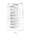
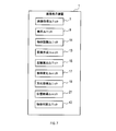
- the image display device 1 has a function configuration realized by the CPU 3 executing a program. As shown in FIG. A distance calculation unit 15, an aspect change unit 17, a direction acquisition unit 19, and a position acquisition unit 21.
- the method for realizing these elements constituting the image display device 1 is not limited to software, and some or all of the elements may be realized using one or a plurality of hardware.
- the electronic circuit may be realized by a digital circuit including a large number of logic circuits, an analog circuit, or a combination thereof.
- the host vehicle includes a camera 23 and a display device 25 in addition to the image display device 1.
- the camera 23 is mounted on the host vehicle.
- the camera 23 photographs the surroundings of the host vehicle and creates a photographed image.
- the camera 23 outputs the captured image to the image display device 1.
- the display device 25 is installed in the passenger compartment of the host vehicle, and the driver of the host vehicle can visually recognize the display device 25.
- the display device 25 displays an image based on a signal sent from the image display device 1.
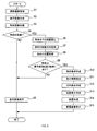
- step 1 of FIG. 3 the image acquisition unit 7 acquires a captured image using the camera 23.
- step 2 the display unit 9 creates a display image from the captured image acquired in step 1 above.
- the display image 27 is a part of the captured image 29. More specifically, the display image 27 is an image obtained by removing the region 31 located at the left and right ends of the captured image 29.
- the region 31 is a region excluding the display image 27 in the captured image 29.
- the object recognition unit 11 performs processing for recognizing an object in the captured image.
- the object include other vehicles and pedestrians.
- a method for recognizing an object for example, a known pattern recognition method can be used.
- step 4 the object recognition unit 11 determines whether or not the object has been recognized in step 3. If the object cannot be recognized, the process proceeds to step 5, and if the object can be recognized, the process proceeds to step 6.
- step 5 the display unit 9 displays the display image 27 created in step 2 on the display device 25.
- step 6 the distance calculation unit 15 calculates a distance R from the host vehicle to the object determined to be recognized in step 4. The distance calculation unit 15 calculates the distance R from the position of the object in the vertical direction in the captured image 29. The distance R is greater as the object is upward in the captured image 29.
- step 7 the direction acquisition unit 19 acquires the movement direction D of the object determined to have been recognized in step 4.
- the direction acquisition unit 19 acquires the moving direction D of the object based on the change between the position of the object in the past captured image 29 and the position of the same object in the latest captured image 29.
- step 8 the position acquisition unit 21 acquires the position P in the captured image 29 of the object determined to be recognized in step 4.
- the position acquisition unit 21 determines whether or not the position P acquired in step 8 exists in the region 31 excluding the display image. If the position P exists in the display image 27, the process proceeds to step 5, and if the position P exists in the region 31 excluding the display image 27, the process proceeds to step 10.
- the image creation unit 13 creates an object display.
- the object display is a display representing the object determined to have been recognized in the step 4.
- the object display includes a region (hereinafter referred to as an object region) including the object determined to be recognized in Step 4 in the captured image 29.
- the object area is sufficiently smaller than the entire captured image 29.
- the object display may be the object region itself or may be a display obtained by adding another display to the object region.
- Other displays include, for example, a frame surrounding the outer periphery of the object region.
- the mode change unit 17 determines the display mode of the object display in the superimposed image 33, which will be described later, according to the distance R calculated in step 6.
- the display mode is the size of the object display.
- the aspect change unit 17 enlarges the object display as the distance R is smaller.
- step 12 the image creating unit 13 creates a direction display representing the moving direction D acquired in step 7.
- the direction display is a display of an arrow indicating the movement direction D.
- step 13 the image creation unit 13 creates a position display representing the position P acquired in step 8.
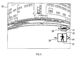
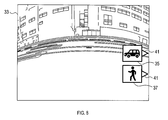
- step 14 the image creation unit 13 adds the object display created in step 10, the direction display created in step 12, and the position display created in step 13 to the display image 27 created in step 2. Are superimposed to create a superimposed image 33 shown in FIG.
- 35 and 37 are object displays created in step 10.
- the object display 35 is an object display representing another vehicle.
- the object display 37 is an object display representing a pedestrian.
- the sizes of the object displays 35 and 37 are the sizes determined in step 11 above.
- the object display 37 is larger than the object display 35 because the object distance R represented by the object display 37 is smaller than the object distance R represented by the object display 35.
- FIG. 5 39 is the direction display created in step 12 above.
- the direction display 39 indicates that the moving direction D of the object is the left direction.
- reference numeral 41 denotes the position display created in step 13.
- the position display 41 indicates that the position P of the object is on the right side of the positions of the object displays 35 and 37.
- step 15 the display unit 9 displays the superimposed image 33 created in step 14 on the display device 25.
- the image display device 1 superimposes object displays 35 and 37 representing objects recognized in a region 31 excluding the display image 27 in the captured image 29 on the display image 27. 33 is created. Then, the image display device 1 displays the superimposed image 33 on the display device 25.
- the user can know that an object exists in the region 31 excluding the display image 27 in the captured image 29 by looking at the object displays 35 and 37 displayed on the superimposed image 33.
- the object displays 35 and 37 reflect the type of the object because they include the object region in the captured image 29. Therefore, the user can know the types of objects existing in the region 31 excluding the display image 27 in the captured image 29 by looking at the object displays 35 and 37.
- the image display device 1 calculates the distance R from the host vehicle to the object. Then, the image display device 1 changes the display mode of the object displays 35 and 37 in the superimposed image 33 according to the distance R. Therefore, the driver can know the distance R from the own vehicle to the object from the display modes of the object displays 35 and 37.
- the image display device 1 changes the sizes of the object displays 35 and 37 in the superimposed image 33 according to the distance R. Therefore, the driver can easily know the distance R from the host vehicle to the object from the size of the object displays 35 and 37.
- the image display device 1 acquires the moving direction D of the object. Then, the image display device 1 superimposes the direction display 39 representing the movement direction D on the display image 27. Therefore, the driver can know the moving direction D from the direction display 39.
- the image display device 1 acquires the position P of the object. Then, the image display device 1 superimposes the position display 41 representing the position P on the display image 27. Therefore, the driver can know the position P from the position display 41.
- Second Embodiment 1 Differences from the First Embodiment Since the basic configuration of the second embodiment is the same as that of the first embodiment, the differences will be described below. Note that the same reference numerals as those in the first embodiment indicate the same configuration, and the preceding description is referred to.
- the object displays 35 and 37 include an object region in the captured image 29.
- the object displays 35 and 37 are different from the first embodiment in that they include icons representing the types of objects.
- the type of icon included in the object displays 35 and 37 and the type of object represented by the object displays 35 and 37 correspond to 1: 1. Therefore, if the type of object is determined, the type of icon corresponding to it is uniquely determined. Examples of the icon include an icon representing a pedestrian and an icon representing another vehicle.
- the object displays 35 and 37 may be icons themselves, or may include other displays in addition to the icons. *
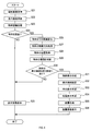
- step 29 the object recognition unit 11 determines the type of object determined to have been recognized in step 24. Examples of the type of object include other vehicles and pedestrians.
- step 30 is the same as the process of step 9 in the first embodiment.
- the image creation unit 13 creates an object display.
- the object display is a display representing the object determined to be recognized in step 24.
- the object display is a display including an icon representing the type of object determined in step 29.
- icons corresponding to the types of objects are stored in the memory 5 in advance.
- the memory 5 stores icons representing pedestrians, icons representing other vehicles, and the like.
- steps 32 to 36 is basically the same as the processing of steps 11 to 15 in the first embodiment.
- the object display superimposed on the display image 27 is a display including an icon representing the type of the object.
- an object display including an icon representing the type of object is displayed.
- the image display device 1 creates a superimposed image 33 by superimposing an object display representing an object recognized in the region 31 excluding the display image 27 in the captured image 29 on the display image. Then, the image display device 1 displays the superimposed image 33 on the display device 25.
- the driver can know that an object exists in the region 31 excluding the display image 27 in the captured image 29 by looking at the object display displayed in the superimposed image 33.
- the object display is a display including an icon representing the type of the object, and therefore reflects the type of the object. Therefore, the driver can know the type of the object existing in the region 31 excluding the display image 27 in the captured image 29 by looking at the object display.
- the image display device 1 may include an object determination unit 43 as shown in FIG.
- the object determination unit 43 determines whether or not there is another object in the display image 27 at a position where the object displays 35 and 37 are superimposed. Examples of other objects include other vehicles and pedestrians.
- the display unit 9 displays the display image 27 on the display device 25 without superimposing the object displays 35 and 37 when the object determination unit 43 determines that another object exists at a position where the object displays 35 and 37 are superimposed. . As a result, it is possible to suppress the object existing in the display image 27 from being hidden by the object displays 35 and 37.
- the superimposed image may be the one shown in FIGS.
- the sizes of the object displays 35 and 37 are constant regardless of the distance R. Further, the direction display 39 is not superimposed.
- the superimposed image 33 shown in FIG. 9 includes a non-display area 45 that does not display the scenery around the host vehicle on both the left and right sides.
- the non-display area 45 is displayed on the left and right sides of the display device 25.
- the object displays 35 and 37 are superimposed on the non-display area 45. Regardless of the distance R, the sizes of the object displays 35 and 37 are constant. Further, the position display 41 is not superimposed.
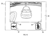
- the superimposed image 33 shown in FIG. 10 a landscape of the subject vehicle viewed from the rear viewpoint is displayed.
- the superimposed image 33 includes a non-display area 45 in which the scenery around the host vehicle is not displayed on both the left and right sides and the lower side.
- the non-display area 45 is displayed on the left and right sides and the lower part of the display device 25.
- the object displays 35 and 37 are superimposed on the non-display area 45. Regardless of the distance R, the sizes of the object displays 35 and 37 are constant. Further, the position display 41 is not superimposed.
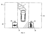
- the superimposed image 33 shown in FIG. 11 a bird's-eye view of the host vehicle viewed from above is displayed.
- the superimposed image 33 includes a non-display area 45 where the scenery around the host vehicle is not displayed on both the left and right sides.
- the non-display area 45 is displayed on the left and right sides of the display device 25.
- the object displays 35 and 37 are superimposed on the non-display area 45. Regardless of the distance R, the sizes of the object displays 35 and 37 are constant. Further, the position display 41 is not superimposed.
- the object area included in the object displays 35 and 37 may be an area including a part of the captured image 29 instead of the entire object.
- the aspect changing unit 17 determines the position of the object displays 35 and 37 in the vertical direction, the color of at least a part of the object displays 35 and 37, and the object display 35 according to the distance R. , 37 may be changed in the presence or absence of blinking.
- the position in the vertical direction of the object displays 35 and 37 can be lowered as the distance R is smaller. Further, for example, when the distance R is small, part or all of the colors of the object displays 35 and 37 can be made conspicuous as compared with the case where the distance R is large. As a part of the object displays 35 and 37 for changing the color, for example, a frame surrounding the object region can be cited.
- the object displays 35 and 37 are blinked, and when the distance R is equal to or larger than the predetermined threshold, the blinking is not performed. Can do.
- a part of the object displays 35 and 37 to be blinked for example, a frame surrounding the object region can be cited. Also in the above case, the driver can know the distance R from the own vehicle to the object from the display modes of the object displays 35 and 37.
- the processing in step 32 in the second embodiment can be the same as described above.
- the object recognition unit 11 may execute the process of recognizing an object in the region 31 excluding the display image 27 and may not execute the process of recognizing the object in the display image 27.
- a plurality of functions of one constituent element in the above embodiment may be realized by a plurality of constituent elements, or a single function of one constituent element may be realized by a plurality of constituent elements. . Further, a plurality of functions possessed by a plurality of constituent elements may be realized by one constituent element, or one function realized by a plurality of constituent elements may be realized by one constituent element. Moreover, you may abbreviate
- at least a part of the configuration of the above embodiment may be added to or replaced with the configuration of the other embodiment.
- all the aspects included in the technical idea specified from the wording described in the claims are embodiments of the present disclosure.
- a system including the image display device as a constituent element, a program for causing a computer to function as the image display device, and a non-transitional actual recording such as a semiconductor memory storing the program
- the present disclosure can also be realized in various forms such as a medium, an image display method, and an image creation method.
Landscapes
- Engineering & Computer Science (AREA)
- Multimedia (AREA)
- Mechanical Engineering (AREA)
- Physics & Mathematics (AREA)
- General Physics & Mathematics (AREA)
- Computer Vision & Pattern Recognition (AREA)
- Theoretical Computer Science (AREA)
- Signal Processing (AREA)
- Closed-Circuit Television Systems (AREA)
- Traffic Control Systems (AREA)
- Image Analysis (AREA)
Applications Claiming Priority (2)
| Application Number | Priority Date | Filing Date | Title |
|---|---|---|---|
| JP2017017449A JP6673242B2 (ja) | 2017-02-02 | 2017-02-02 | 画像表示装置 |
| JP2017-017449 | 2017-08-11 |
Publications (1)
| Publication Number | Publication Date |
|---|---|
| WO2018143285A1 true WO2018143285A1 (ja) | 2018-08-09 |
Family
ID=63040713
Family Applications (1)
| Application Number | Title | Priority Date | Filing Date |
|---|---|---|---|
| PCT/JP2018/003248 Ceased WO2018143285A1 (ja) | 2017-02-02 | 2018-01-31 | 画像表示装置 |
Country Status (2)
| Country | Link |
|---|---|
| JP (1) | JP6673242B2 (cg-RX-API-DMAC7.html) |
| WO (1) | WO2018143285A1 (cg-RX-API-DMAC7.html) |
Families Citing this family (1)
| Publication number | Priority date | Publication date | Assignee | Title |
|---|---|---|---|---|
| KR102974736B1 (ko) * | 2019-12-26 | 2026-06-09 | 주식회사 에스엘미러텍 | 차량의 카메라 모니터링 장치 |
Citations (4)
| Publication number | Priority date | Publication date | Assignee | Title |
|---|---|---|---|---|
| JP2007295043A (ja) * | 2006-04-20 | 2007-11-08 | Matsushita Electric Ind Co Ltd | 車両周囲監視装置 |
| JP2010130646A (ja) * | 2008-12-01 | 2010-06-10 | Aisin Seiki Co Ltd | 車両周辺確認装置 |
| JP2013005233A (ja) * | 2011-06-16 | 2013-01-07 | Aisin Seiki Co Ltd | 車両周辺監視装置 |
| JP2014086969A (ja) * | 2012-10-25 | 2014-05-12 | Aisin Seiki Co Ltd | 画像表示制御装置 |
-
2017
- 2017-02-02 JP JP2017017449A patent/JP6673242B2/ja active Active
-
2018
- 2018-01-31 WO PCT/JP2018/003248 patent/WO2018143285A1/ja not_active Ceased
Patent Citations (4)
| Publication number | Priority date | Publication date | Assignee | Title |
|---|---|---|---|---|
| JP2007295043A (ja) * | 2006-04-20 | 2007-11-08 | Matsushita Electric Ind Co Ltd | 車両周囲監視装置 |
| JP2010130646A (ja) * | 2008-12-01 | 2010-06-10 | Aisin Seiki Co Ltd | 車両周辺確認装置 |
| JP2013005233A (ja) * | 2011-06-16 | 2013-01-07 | Aisin Seiki Co Ltd | 車両周辺監視装置 |
| JP2014086969A (ja) * | 2012-10-25 | 2014-05-12 | Aisin Seiki Co Ltd | 画像表示制御装置 |
Also Published As
| Publication number | Publication date |
|---|---|
| JP2018125749A (ja) | 2018-08-09 |
| JP6673242B2 (ja) | 2020-03-25 |
Similar Documents
| Publication | Publication Date | Title |
|---|---|---|
| JP5143235B2 (ja) | 制御装置および車両周囲監視装置 | |
| CN106660495B (zh) | 车辆用显示装置以及车辆用显示方法 | |
| WO2016002163A1 (ja) | 画像表示装置、画像表示方法 | |
| EP3351417A1 (en) | Display apparatus for vehicle and display method for vehicle | |
| JP6375633B2 (ja) | 車両周辺画像表示装置、車両周辺画像表示方法 | |
| US9826166B2 (en) | Vehicular surrounding-monitoring control apparatus | |
| US20180229656A1 (en) | Apparatus for presenting support images to a driver and method thereof | |
| JP5404932B2 (ja) | 交通状況のビデオデータと間隔データを組み合わせて視覚的に表示するための方法および装置 | |
| JP2010130646A (ja) | 車両周辺確認装置 | |
| CN109314765B (zh) | 车辆用显示控制装置、显示系统、显示控制方法以及程序 | |
| CN113678433A (zh) | 车辆周边图像生成装置、车辆周边显示系统及车辆周边显示方法 | |
| JP6152261B2 (ja) | 車載用駐車枠認識装置 | |
| KR101428094B1 (ko) | 차선이 표시된 측방/후방 영상 제공 시스템 | |
| JP2018074411A (ja) | 物体検出装置及び物体検出方法 | |
| EP3396620B1 (en) | Display control device and display control method | |
| JP6032141B2 (ja) | 走行路面標示検知装置および走行路面標示検知方法 | |
| JP2015171106A (ja) | 車両周辺画像表示装置、車両周辺画像表示方法 | |
| JP6407596B2 (ja) | 画像処理装置、及び、運転支援システム | |
| JP6313999B2 (ja) | 物体検出装置、及び、物体検出システム | |
| JP6673242B2 (ja) | 画像表示装置 | |
| JP6256508B2 (ja) | 電子ミラー制御装置 | |
| JP5155204B2 (ja) | 白線検出装置 | |
| JP6855254B2 (ja) | 画像処理装置、画像処理システム、及び、画像処理方法 | |
| JP6464952B2 (ja) | 表示制御装置、表示制御プログラム及び表示制御方法 | |
| JP4598011B2 (ja) | 車両用表示装置 |
Legal Events
| Date | Code | Title | Description |
|---|---|---|---|
| 121 | Ep: the epo has been informed by wipo that ep was designated in this application |
Ref document number: 18747100 Country of ref document: EP Kind code of ref document: A1 |
|
| NENP | Non-entry into the national phase |
Ref country code: DE |
|
| 122 | Ep: pct application non-entry in european phase |
Ref document number: 18747100 Country of ref document: EP Kind code of ref document: A1 |