WO2018143087A1 - 超音波出力装置 - Google Patents
超音波出力装置 Download PDFInfo
- Publication number
- WO2018143087A1 WO2018143087A1 PCT/JP2018/002493 JP2018002493W WO2018143087A1 WO 2018143087 A1 WO2018143087 A1 WO 2018143087A1 JP 2018002493 W JP2018002493 W JP 2018002493W WO 2018143087 A1 WO2018143087 A1 WO 2018143087A1
- Authority
- WO
- WIPO (PCT)
- Prior art keywords
- ultrasonic output
- ultrasonic
- output device
- holding
- unit
- Prior art date
- Legal status (The legal status is an assumption and is not a legal conclusion. Google has not performed a legal analysis and makes no representation as to the accuracy of the status listed.)
- Ceased
Links
Images


Classifications
-
- H—ELECTRICITY
- H04—ELECTRIC COMMUNICATION TECHNIQUE
- H04R—LOUDSPEAKERS, MICROPHONES, GRAMOPHONE PICK-UPS OR LIKE ACOUSTIC ELECTROMECHANICAL TRANSDUCERS; ELECTRIC HEARING AIDS; PUBLIC ADDRESS SYSTEMS
- H04R1/00—Details of transducers, loudspeakers or microphones
- H04R1/02—Casings; Cabinets ; Supports therefor; Mountings therein
- H04R1/025—Arrangements for fixing loudspeaker transducers, e.g. in a box, furniture
-
- H—ELECTRICITY
- H04—ELECTRIC COMMUNICATION TECHNIQUE
- H04R—LOUDSPEAKERS, MICROPHONES, GRAMOPHONE PICK-UPS OR LIKE ACOUSTIC ELECTROMECHANICAL TRANSDUCERS; ELECTRIC HEARING AIDS; PUBLIC ADDRESS SYSTEMS
- H04R1/00—Details of transducers, loudspeakers or microphones
- H04R1/02—Casings; Cabinets ; Supports therefor; Mountings therein
-
- B—PERFORMING OPERATIONS; TRANSPORTING
- B06—GENERATING OR TRANSMITTING MECHANICAL VIBRATIONS IN GENERAL
- B06B—METHODS OR APPARATUS FOR GENERATING OR TRANSMITTING MECHANICAL VIBRATIONS OF INFRASONIC, SONIC, OR ULTRASONIC FREQUENCY, e.g. FOR PERFORMING MECHANICAL WORK IN GENERAL
- B06B1/00—Methods or apparatus for generating mechanical vibrations of infrasonic, sonic, or ultrasonic frequency
- B06B1/02—Methods or apparatus for generating mechanical vibrations of infrasonic, sonic, or ultrasonic frequency making use of electrical energy
-
- H—ELECTRICITY
- H04—ELECTRIC COMMUNICATION TECHNIQUE
- H04R—LOUDSPEAKERS, MICROPHONES, GRAMOPHONE PICK-UPS OR LIKE ACOUSTIC ELECTROMECHANICAL TRANSDUCERS; ELECTRIC HEARING AIDS; PUBLIC ADDRESS SYSTEMS
- H04R1/00—Details of transducers, loudspeakers or microphones
- H04R1/20—Arrangements for obtaining desired frequency or directional characteristics
- H04R1/22—Arrangements for obtaining desired frequency or directional characteristics for obtaining desired frequency characteristic only
- H04R1/227—Arrangements for obtaining desired frequency or directional characteristics for obtaining desired frequency characteristic only using transducers reproducing the same frequency band
-
- B—PERFORMING OPERATIONS; TRANSPORTING
- B06—GENERATING OR TRANSMITTING MECHANICAL VIBRATIONS IN GENERAL
- B06B—METHODS OR APPARATUS FOR GENERATING OR TRANSMITTING MECHANICAL VIBRATIONS OF INFRASONIC, SONIC, OR ULTRASONIC FREQUENCY, e.g. FOR PERFORMING MECHANICAL WORK IN GENERAL
- B06B3/00—Methods or apparatus specially adapted for transmitting mechanical vibrations of infrasonic, sonic, or ultrasonic frequency
-
- H—ELECTRICITY
- H04—ELECTRIC COMMUNICATION TECHNIQUE
- H04R—LOUDSPEAKERS, MICROPHONES, GRAMOPHONE PICK-UPS OR LIKE ACOUSTIC ELECTROMECHANICAL TRANSDUCERS; ELECTRIC HEARING AIDS; PUBLIC ADDRESS SYSTEMS
- H04R2201/00—Details of transducers, loudspeakers or microphones covered by H04R1/00 but not provided for in any of its subgroups
- H04R2201/02—Details casings, cabinets or mounting therein for transducers covered by H04R1/02 but not provided for in any of its subgroups
- H04R2201/029—Manufacturing aspects of enclosures transducers
Definitions
- the present disclosure relates to an ultrasonic output device that outputs ultrasonic waves.
- Patent Document 1 discloses a configuration in which an ultrasonic output unit is installed in a holding unit such as a pedestal.
- an ultrasonic output device that outputs ultrasonic waves can stabilize the output characteristics of the ultrasonic waves.
- the ultrasonic output device of one side of this indication is provided with an ultrasonic output part, a holding part, and a cylindrical part.
- the ultrasonic output unit is configured to output an ultrasonic wave corresponding to the input signal in a predetermined traveling direction, and is provided with at least one.
- the holding unit is configured to hold the ultrasonic output unit.
- the cylindrical portion surrounds the periphery in the direction orthogonal to the traveling direction of the ultrasonic output portion, and is configured to be connected to the holding portion.
- the holding portion is connected to the cylindrical portion, the rigidity of the holding portion can be improved. Therefore, it is possible to make it difficult for vibration due to ultrasonic waves to be transmitted to the holding portion, and it is possible to stabilize the output characteristics of the ultrasonic waves.
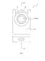
- 1 is a cross-sectional view taken along the line II of an ultrasonic output device according to a first embodiment. It is a front view of the ultrasonic output device in a 1st embodiment. It is a perspective view of the ultrasonic output device in a 1st embodiment. It is IV-IV sectional drawing of the ultrasonic output device in 2nd Embodiment. It is a front view of the ultrasonic output device in a 2nd embodiment. It is a perspective view of the ultrasonic output device in a 2nd embodiment.
- the ultrasonic output device 1 of the first embodiment shown in FIGS. 1, 2, and 3 is a device that outputs ultrasonic waves.
- the ultrasonic output device 1 includes an ultrasonic output unit 10 and a case unit 20.
- the ultrasonic output unit 10 is configured as a parametric speaker that outputs an audible sound using ultrasonic waves.
- An input signal is input to the ultrasonic output unit 10 from an ultrasonic amplifier (not shown) via a lead wire 34 with a connector 36 shown in FIG. 3, and an audible sound having directivity is output according to the input signal.
- an input signal a signal capable of amplitude-modulating an ultrasonic waveform having a predetermined frequency (for example, 40 kHz) and outputting a predetermined audible sound is input.
- the ultrasonic output unit 10 is configured in, for example, a cylindrical shape as shown in FIGS. 1, 2, and 3, and an ultrasonic wave corresponding to an input signal is transmitted from the sound wave output surface 10A that is one end surface to the sound wave output surface 10A. Is output in the direction of travel which is the vertical direction with respect to. The advancing direction is rightward in FIG. 1 and forward in FIG. 1, 2, and 3 show an example in which only one ultrasonic output unit 10 is provided, but a plurality of ultrasonic output units 10 may be provided.
- the case portion 20 is made of a metal such as stainless steel or an aluminum alloy, and is a member that surrounds and holds the ultrasonic output portion 10.
- the case portion 20 is formed in a cylindrical shape having step portions 20A and 20B at the inner diameter portion and the outer diameter portion.
- the case portion 20 is configured such that the inner and outer diameters on the traveling direction side are increased by the step portions 20A and 20B.
- the columnar shape and the cylindrical shape include a substantially columnar shape and a substantially cylindrical shape.
- the step portion 20 ⁇ / b> A having an inner diameter functions as the holding portion 22.
- the holding unit 22 holds the ultrasonic output unit 10 by contacting the surface of the ultrasonic output unit 10 opposite to the traveling direction directly or indirectly via another member. In the present embodiment, the holding unit 22 holds the ultrasonic output unit 10 via a buffer member 14 described later.
- the portion of the case portion 20 having a large inner diameter functions as the cylindrical portion 24.
- the cylindrical portion 24 surrounds the periphery in a direction orthogonal to the traveling direction of the ultrasonic output unit 10.
- a gap portion 12 is provided between the tubular portion 24 and the ultrasonic output portion 10 such that the tubular portion 24 and the ultrasonic output portion 10 are spaced apart from each other.
- the gap portion 12 is configured to make it difficult for vibration of the ultrasonic output unit 10 to be transmitted to the cylindrical portion 24.
- the cylindrical portion 24 is configured integrally with the holding portion 22.
- the length L1 from the holding portion 22 to the end portion on the traveling direction side is set equal to the length L1 from the holding portion 22 to the sound wave output surface 10A in the ultrasonic output portion 10. Yes.
- the length from the holding unit 22 to the end portion on the traveling direction side may be L2, which is a length less than the length L1 from the holding unit 22 to the sound wave output surface 10A of the ultrasonic output unit 10.
- the ultrasonic output device 1 further includes a buffer member 14 between the ultrasonic output unit 10 and the holding unit 22.
- the buffer member 14 is made of a material softer than the holding unit 22. As to whether the buffer member 14 and the vibration suppressing member 32 described later are hard or soft, a substance that easily absorbs ultrasonic vibration is made softer.
- a sample of the same shape fix one end of the sample and apply a load to the other end to release the other end To make it vibrate.
- a substance having a low frequency at this time may be adopted as a softer substance.
- a resin gasket such as rubber, a rubber plate, a rubber adhesive, or the like can be employed.
- the ultrasonic output device 1 further includes a support part 30 and a vibration suppressing member 32.
- the support unit 30 supports the case unit 20 in a state where the ultrasonic output unit 10 is held.
- the support portion 30 supports the case portion 20 via the vibration suppressing member 32 on the rear side in the traveling direction with respect to the step portion 20B having an outer diameter in the case portion 20.
- the vibration suppressing member 32 is a ring-shaped member disposed between the holding unit 22 and the support unit 30 and is made of a material softer than the holding unit 22. [1-2. effect] According to the first embodiment described in detail above, the following effects are obtained.
- the ultrasonic output device 1 includes an ultrasonic output unit 10, a holding unit 22, and a cylindrical unit 24.
- the ultrasonic output unit 10 is configured to output an ultrasonic wave corresponding to an input signal in a traveling direction set in advance, and is provided with at least one.
- the holding unit 22 is configured to hold the ultrasonic output unit 10.
- the cylindrical part 24 surrounds the periphery in a direction orthogonal to the traveling direction of the ultrasonic output part 10 and is configured to be connected to the holding part 22.
- the rigidity of the holding portion 22 can be improved. Therefore, it is possible to make it difficult for vibration caused by ultrasonic waves to be transmitted to the holding unit 22, so that the output characteristics of the ultrasonic waves can be stabilized.
- the ultrasonic output device 1 further includes a buffer member 14 made of a material softer than the holding unit 22 between the ultrasonic output unit 10 and the holding unit 22. According to such an ultrasonic output device 1, the shock can be absorbed by the buffer member 14, so that the vibration due to the ultrasonic wave can be more difficult to be transmitted to the holding unit 22.
- the ultrasonic output device 1 described above includes the support unit 30 that supports the holding unit 22, and the vibration suppression member 32 that is formed between the holding unit 22 and the support unit 30 with a material softer than the holding unit 22. And further comprising.
- the cylindrical portion 24 has a length L2 from the holding portion 22 to the end portion on the traveling direction side, from the holding portion 22 to the sound wave output surface 10A in the ultrasonic output portion 10. It is comprised so that it may become below length L1.
- the length L2 from the holding unit 22 to the end portion on the traveling direction side is equal to or less than the length L1 from the holding unit 22 to the sound wave output surface 10A in the ultrasonic output unit 10. Since it is comprised, it can suppress receiving the interference of the ultrasonic wave output from 10 A of sound wave output surfaces reflecting on the cylindrical part 24, etc.
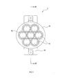
- the second embodiment is different from the first embodiment in that a plurality of ultrasonic output units 10 are provided.
- the ultrasonic output device 2 includes a plurality of ultrasonic output units 10. Input signals having the same frequency and the same phase are input to the plurality of ultrasonic output units 10.
- a case part 50 having a holding part 52 and a cylindrical part 54 is provided in place of the case part 20 having the holding part 22 and the cylindrical part 24 described above. Further, a buffer member 44, a support portion 60, and a vibration suppression member 62 are provided instead of the buffer member 14, the support portion 30, and the vibration suppression member 32 described above.
- the holding part 52, the cylindrical part 54, the buffer member 44, the support part 60, and the vibration suppression member 62 are substantially the same as the above-described holding part 22, cylindrical part 24, buffer member 14, support part 30, and vibration suppression member 32. It has a function.
- the plurality of ultrasonic output units 10 are arranged side by side so that there is no gap between them. Specifically, the other six ultrasonic output units 10 are arranged around one ultrasonic output unit 10 as a center.
- the cylindrical portion 54 is configured such that the cross-sectional shape of the inner peripheral portion follows the outer peripheral shape of the plurality of ultrasonic output units 10 when the plurality of ultrasonic output units 10 are arranged side by side. Between the inner peripheral part of the cylindrical part 54 and the outer peripheral part of the ultrasonic output part 10, a gap part 42 having a constant interval is formed between the inner peripheral part of the cylindrical part 54 and the ultrasonic output part 10. Is done.
- the buffer member 44 is configured to be in contact with the surface on the opposite side of the traveling direction in all the ultrasonic output units 10. [2-3. effect] According to 2nd Embodiment explained in full detail above, there exists the effect (1a) of 1st Embodiment mentioned above, and also there exist the following effects.
- the ultrasonic output unit 10 includes a plurality of ultrasonic output units 10, and the cylindrical unit 24 has a plurality of ultrasonic output units 10 arranged side by side in a cross-sectional shape of the inner periphery. It is comprised so that the outer periphery shape of the ultrasonic output part 10 may be followed.
- the cylindrical portion 24 since the inner peripheral portion of the cylindrical portion 24 follows the shape of the outer periphery of the plurality of ultrasonic output portions 10, the cylindrical portion according to the shape of the ultrasonic output portion 10. A part of 24 can be made thick. Therefore, the rigidity of the cylindrical part 24 can be improved.
- the plurality of ultrasonic output units 10 are configured such that there is no gap between them. According to such an ultrasonic output device 2, a plurality of ultrasonic output units 10 are arranged without gaps therebetween, so that variation in characteristics is suppressed, and a plurality of ultrasonic output units 10 are combined into one ultrasonic output unit 10. Can be easily used as.
- input signals having the same phase are input to the plurality of ultrasonic output units 10 respectively, but the present invention is not limited to this.
- a configuration in which input signals having the same frequency and different phases are input to the plurality of ultrasonic output units 10 and the directivity is changed by causing the output ultrasonic waves to interfere with each other may be employed.
- the buffer members 14 and 44 and the vibration suppression members 32 and 62 are provided. However, at least one of the buffer members 14 and 44 and the vibration suppression members 32 and 62 is not an essential configuration.
- a plurality of functions of one constituent element in the above embodiment may be realized by a plurality of constituent elements, or a single function of one constituent element may be realized by a plurality of constituent elements. . Further, a plurality of functions possessed by a plurality of constituent elements may be realized by one constituent element, or one function realized by a plurality of constituent elements may be realized by one constituent element. Moreover, you may abbreviate
- the present disclosure can be realized in various forms such as a system including the ultrasonic output devices 1 and 2 as components.
Landscapes
- Engineering & Computer Science (AREA)
- Physics & Mathematics (AREA)
- Acoustics & Sound (AREA)
- Signal Processing (AREA)
- Mechanical Engineering (AREA)
- Health & Medical Sciences (AREA)
- Otolaryngology (AREA)
- Transducers For Ultrasonic Waves (AREA)
- Circuit For Audible Band Transducer (AREA)
Priority Applications (3)
| Application Number | Priority Date | Filing Date | Title |
|---|---|---|---|
| CN201880008969.XA CN110291796A (zh) | 2017-02-01 | 2018-01-26 | 超声波输出装置 |
| DE112018000625.5T DE112018000625T5 (de) | 2017-02-01 | 2018-01-26 | Ultraschallwellenausgabevorrichtung |
| US16/524,346 US20190356973A1 (en) | 2017-02-01 | 2019-07-29 | Ultrasonic wave output device |
Applications Claiming Priority (2)
| Application Number | Priority Date | Filing Date | Title |
|---|---|---|---|
| JP2017-016808 | 2017-02-01 | ||
| JP2017016808A JP6631549B2 (ja) | 2017-02-01 | 2017-02-01 | 超音波出力装置 |
Related Child Applications (1)
| Application Number | Title | Priority Date | Filing Date |
|---|---|---|---|
| US16/524,346 Continuation US20190356973A1 (en) | 2017-02-01 | 2019-07-29 | Ultrasonic wave output device |
Publications (1)
| Publication Number | Publication Date |
|---|---|
| WO2018143087A1 true WO2018143087A1 (ja) | 2018-08-09 |
Family
ID=63040589
Family Applications (1)
| Application Number | Title | Priority Date | Filing Date |
|---|---|---|---|
| PCT/JP2018/002493 Ceased WO2018143087A1 (ja) | 2017-02-01 | 2018-01-26 | 超音波出力装置 |
Country Status (5)
| Country | Link |
|---|---|
| US (1) | US20190356973A1 (https=) |
| JP (1) | JP6631549B2 (https=) |
| CN (1) | CN110291796A (https=) |
| DE (1) | DE112018000625T5 (https=) |
| WO (1) | WO2018143087A1 (https=) |
Cited By (1)
| Publication number | Priority date | Publication date | Assignee | Title |
|---|---|---|---|---|
| JP2020039051A (ja) * | 2018-09-04 | 2020-03-12 | 株式会社ディスコ | 超音波音圧計 |
Families Citing this family (1)
| Publication number | Priority date | Publication date | Assignee | Title |
|---|---|---|---|---|
| JP6665820B2 (ja) | 2017-03-28 | 2020-03-13 | 株式会社デンソー | 超音波出力装置 |
Citations (6)
| Publication number | Priority date | Publication date | Assignee | Title |
|---|---|---|---|---|
| JPS6085493A (ja) * | 1983-10-17 | 1985-05-14 | Hitachi Ltd | ブ−トストラツプ回路 |
| JP2001298794A (ja) * | 2000-04-14 | 2001-10-26 | Yazaki Corp | 開放型超音波センサ |
| JP2001337172A (ja) * | 2000-05-29 | 2001-12-07 | Niles Parts Co Ltd | 超音波検知器 |
| JP2008079909A (ja) * | 2006-09-28 | 2008-04-10 | Fujifilm Corp | 超音波用探触子及び超音波撮像装置 |
| JP2012257088A (ja) * | 2011-06-09 | 2012-12-27 | Tokai Univ | パラメトリックスピーカ |
| WO2015155989A1 (ja) * | 2014-04-08 | 2015-10-15 | 株式会社デンソー | 車両用超音波センサ及びそれを備えた車両用距離検出器 |
Family Cites Families (6)
| Publication number | Priority date | Publication date | Assignee | Title |
|---|---|---|---|---|
| JPS6085493U (ja) * | 1983-11-16 | 1985-06-12 | オムロン株式会社 | 超音波振動子のシ−ルド構造 |
| JP4591302B2 (ja) * | 2005-10-12 | 2010-12-01 | 株式会社デンソー | 超音波センサの取付構造 |
| JP4305543B2 (ja) * | 2007-03-29 | 2009-07-29 | パナソニック株式会社 | 超音波送受信器およびそれを用いた超音波流量計 |
| JP2011162073A (ja) | 2010-02-10 | 2011-08-25 | Tabuchi Electric Co Ltd | 電動車両 |
| JP5522311B2 (ja) * | 2011-10-04 | 2014-06-18 | 株式会社村田製作所 | 超音波センサおよびその製造方法 |
| JP2017016808A (ja) | 2015-06-30 | 2017-01-19 | 東日本旅客鉄道株式会社 | 停電補償付き電源装置およびそれを用いた夜間照明システム |
-
2017
- 2017-02-01 JP JP2017016808A patent/JP6631549B2/ja not_active Expired - Fee Related
-
2018
- 2018-01-26 WO PCT/JP2018/002493 patent/WO2018143087A1/ja not_active Ceased
- 2018-01-26 DE DE112018000625.5T patent/DE112018000625T5/de not_active Withdrawn
- 2018-01-26 CN CN201880008969.XA patent/CN110291796A/zh active Pending
-
2019
- 2019-07-29 US US16/524,346 patent/US20190356973A1/en not_active Abandoned
Patent Citations (6)
| Publication number | Priority date | Publication date | Assignee | Title |
|---|---|---|---|---|
| JPS6085493A (ja) * | 1983-10-17 | 1985-05-14 | Hitachi Ltd | ブ−トストラツプ回路 |
| JP2001298794A (ja) * | 2000-04-14 | 2001-10-26 | Yazaki Corp | 開放型超音波センサ |
| JP2001337172A (ja) * | 2000-05-29 | 2001-12-07 | Niles Parts Co Ltd | 超音波検知器 |
| JP2008079909A (ja) * | 2006-09-28 | 2008-04-10 | Fujifilm Corp | 超音波用探触子及び超音波撮像装置 |
| JP2012257088A (ja) * | 2011-06-09 | 2012-12-27 | Tokai Univ | パラメトリックスピーカ |
| WO2015155989A1 (ja) * | 2014-04-08 | 2015-10-15 | 株式会社デンソー | 車両用超音波センサ及びそれを備えた車両用距離検出器 |
Cited By (1)
| Publication number | Priority date | Publication date | Assignee | Title |
|---|---|---|---|---|
| JP2020039051A (ja) * | 2018-09-04 | 2020-03-12 | 株式会社ディスコ | 超音波音圧計 |
Also Published As
| Publication number | Publication date |
|---|---|
| JP2018125721A (ja) | 2018-08-09 |
| JP6631549B2 (ja) | 2020-01-15 |
| CN110291796A (zh) | 2019-09-27 |
| US20190356973A1 (en) | 2019-11-21 |
| DE112018000625T5 (de) | 2019-12-12 |
Similar Documents
| Publication | Publication Date | Title |
|---|---|---|
| US20090208039A1 (en) | Hybrid actuator, loudspeaker and sound output method | |
| CN103650531B (zh) | 具有力抵消配置的扬声器 | |
| US8254603B2 (en) | Speaker apparatus and method for driving speaker | |
| KR101368697B1 (ko) | 초음파 진동장치 | |
| EP2157814B1 (en) | Speaker device | |
| RU2011142163A (ru) | Устройство громкоговорителя | |
| WO2018143087A1 (ja) | 超音波出力装置 | |
| US7654362B2 (en) | Speaker and method of outputting acoustic sound | |
| JP6687235B2 (ja) | 検出装置及び検出方法 | |
| JP6665820B2 (ja) | 超音波出力装置 | |
| JP6932029B2 (ja) | ホーンスピーカー、スピーカーユニット、メガホン、アダプター、及び放送システム | |
| US12015888B2 (en) | Acoustic device and vibration damping method | |
| JP2006135779A (ja) | 指向性複合型スピーカ | |
| JPWO2018143232A1 (ja) | 音響装置、及び音響制御装置 | |
| JP2005020576A (ja) | スピーカ装置 | |
| JP2018125721A5 (https=) | ||
| WO2019054440A1 (ja) | 超音波出力装置 | |
| EP2387253A3 (en) | Audio extension system | |
| JP2006287673A (ja) | 音波センサ | |
| US20180250710A1 (en) | Acoustic sensor for emitting and/or receiving acoustic signals | |
| KR102046392B1 (ko) | 음질을 향상시킨 스피커 | |
| JP2010098541A (ja) | スピーカ、及び、スピーカ用エッジ | |
| KR20140027617A (ko) | 공동 음원을 갖는 다중채널 압전소자 | |
| WO2010013328A1 (ja) | スピーカ装置 | |
| WO2021134184A1 (zh) | 发声器件 |
Legal Events
| Date | Code | Title | Description |
|---|---|---|---|
| 121 | Ep: the epo has been informed by wipo that ep was designated in this application |
Ref document number: 18747308 Country of ref document: EP Kind code of ref document: A1 |
|
| 122 | Ep: pct application non-entry in european phase |
Ref document number: 18747308 Country of ref document: EP Kind code of ref document: A1 |