WO2018138797A1 - 静止誘導電器 - Google Patents
静止誘導電器 Download PDFInfo
- Publication number
- WO2018138797A1 WO2018138797A1 PCT/JP2017/002489 JP2017002489W WO2018138797A1 WO 2018138797 A1 WO2018138797 A1 WO 2018138797A1 JP 2017002489 W JP2017002489 W JP 2017002489W WO 2018138797 A1 WO2018138797 A1 WO 2018138797A1
- Authority
- WO
- WIPO (PCT)
- Prior art keywords
- spacers
- winding
- circumferential direction
- spacer
- static induction
- Prior art date
- Legal status (The legal status is an assumption and is not a legal conclusion. Google has not performed a legal analysis and makes no representation as to the accuracy of the status listed.)
- Ceased
Links
Images





Classifications
-
- H—ELECTRICITY
- H01—ELECTRIC ELEMENTS
- H01F—MAGNETS; INDUCTANCES; TRANSFORMERS; SELECTION OF MATERIALS FOR THEIR MAGNETIC PROPERTIES
- H01F27/00—Details of transformers or inductances, in general
- H01F27/28—Coils; Windings; Conductive connections
- H01F27/30—Fastening or clamping coils, windings, or parts thereof together; Fastening or mounting coils or windings on core, casing, or other support
-
- H—ELECTRICITY
- H01—ELECTRIC ELEMENTS
- H01F—MAGNETS; INDUCTANCES; TRANSFORMERS; SELECTION OF MATERIALS FOR THEIR MAGNETIC PROPERTIES
- H01F37/00—Fixed inductances not covered by group H01F17/00
Definitions
- the embodiment of the present invention relates to a static induction machine.
- a static induction device such as a transformer or a reactor is composed of a static induction main body composed of a winding, an iron core, etc., a container that houses the static induction electric main body, and an insulating and cooling container filled in the container.
- a cooling medium may generate noise when the vibration of the windings generated by energizing the windings is transmitted to the vessel wall via the connection between the static induction electric appliance body and the vessel or a cooling medium. is there.
- static induction appliances have a structure in which large electric field energy and magnetic field energy are confined in a small space due to increase in capacity, reduction in size, and weight reduction, and vibration and noise tend to increase.
- the problem to be solved by the present invention is to provide a static induction electric appliance capable of suppressing noise during energization.
- the static induction electric appliance of the embodiment has an iron core, a winding, a container, and a spacer unit.
- the iron core has a leg portion and a pair of yoke portions.
- the leg portion extends along the first direction.
- the pair of yoke portions extend along the second direction intersecting the first direction from both end portions of the leg portion.
- the winding is wound around the leg portion and fastened in the first direction by a pair of yoke portions.
- the container houses the iron core and the winding.
- the spacer unit has a plurality of spacers.
- the plurality of spacers are sandwiched between windings adjacent in the first direction.
- the plurality of spacers are arranged side by side in the circumferential direction around the winding axis of the winding.
- the spacer unit differs in the amount of distortion with respect to the force in the first direction at a position in the circumferential direction.
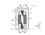
- the front sectional view of the static induction appliance concerning a 1st embodiment.
- the front sectional view of the static induction appliance concerning a 1st embodiment.
- wire of FIG. The figure which shows distribution in the 1st direction of the electromagnetic force of the 1st direction which acts on a coil
- Sectional drawing of the static induction appliance which concerns on 2nd Embodiment.
- FIG. 1 is a front cross-sectional view of a stationary induction device according to a first embodiment.
- a static induction electric machine 1 includes a static induction electric machine body 4 having an iron core 2 and a winding 3, a container 5 that houses the stationary induction electric machine body 4, and an insulating and filling container 5. And an insulating oil 6 for cooling.
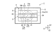
- FIG. 2 is a side cross-sectional view of the stationary induction device according to the first embodiment.
- 3 is a cross-sectional view taken along line III-III in FIG.
- the container 5 is formed in a rectangular parallelepiped shape.
- the container 5 is made of, for example, stainless steel.
- the side wall of the container 5 extends along the vertical direction.
- the top wall of the container 5 extends along the horizontal direction.
- the stationary induction main body 4 is fixed.
- the iron core 2 has a leg portion 21 extending along the first direction L ⁇ b> 1 along the vertical direction and a central portion connected to the upper end portion of the leg portion 21 and the upper end of the leg portion 21.
- a first yoke portion 22 extending along a second direction L2 orthogonal to the first direction L1 from the portion, and a central portion connected to the lower end portion of the leg portion 21 and from the lower end portion of the leg portion 21 in the second direction L2.
- a pair of connecting leg portions 24 that connect the tip end portion of the first yoke portion 22 and the tip end portion of the second yoke portion 23.
- the iron core 2 is formed by laminating a plurality of electromagnetic steel plates in a third direction L3 orthogonal to the first direction L1 and the second direction L2.
- the plurality of electromagnetic steel sheets include an upper core fastening member 10A that sandwiches the upper end of the iron core 2 from both sides in the third direction L3, and a lower iron core fastening member 10B that sandwiches the lower end of the iron core 2 from both sides in the third direction L3. , Is supported by.
- the upper iron core fastening member 10A extends along the second direction L2.
- the lower surface of the upper iron core fastening member 10A extends along both directions of the second direction L2 and the third direction L3.
- the lower iron core fastening member 10B extends along the second direction L2.
- the upper surface of the lower iron core fastening member 10B extends along both directions of the second direction L2 and the third direction L3.
- the winding 3 is wound around the leg portion 21 of the iron core 2 in a cylindrical shape.
- the winding axis O of the winding 3 extends along the first direction L1.
- the winding 3 forms a plurality of coils 31 stacked in the first direction L1.
- the winding 3 has a gap with respect to the leg portion 21 of the iron core 2.
- a member that holds a gap between the winding 3 and the leg 21 may be disposed between the winding 3 and the leg 21.
- the winding 3 is fastened in the first direction L1 by the first yoke portion 22 and the second yoke portion 23 via the winding fastening member 11.
- the winding 3 is sandwiched between the lower surface of the upper iron core fastening member 10A and the upper surface of the lower iron core fastening member 10B via the winding fastening member 11.
- the circumferential direction of the winding 3 around the winding axis O is simply referred to as “circumferential direction”, and the direction extending radially from the winding axis O perpendicular to the first direction L1 is “radial direction”. That's it.
- the winding fastening member 11 is disposed between the first yoke portion 22 and the winding 3 in the first direction L1 and between the second yoke portion 23 and the winding 3.
- the winding fastening member 11 disposed on the upper side of the winding 3 has a plurality of blocks 11a disposed at a pitch of approximately 90 ° in the circumferential direction.
- the winding fastening member 11 disposed on the upper side of the winding 3 is in intermittent contact with the winding 3 in the circumferential direction.
- the block 11a is made of an insulating material such as wood.
- the plurality of blocks 11a are disposed between the winding 3 and the first yoke portion 22, and between the winding 3 and the upper iron core fastening member 10A.
- the plurality of blocks 11a are arranged on a straight line extending along the second direction L2 through the winding axis O when viewed from the first direction L1, and along the third direction L3 through the winding axis O. It is arranged at a position on the extending straight line.
- the lower iron core fastening member 10B is the same as the upper iron core fastening member 10A.
- FIG. 4 is an enlarged view of a portion IV in FIG.
- FIG. 5 is a cross-sectional view taken along line VV in FIG.
- the positions of the first yoke portion 22 and the second yoke portion 23 as viewed from the first direction L1 are indicated by two-dot chain lines.
- the stationary induction device main body 4 further includes a spacer unit 40.
- the spacer unit 40 has a plurality (12 in this embodiment) of spacers 41a to 41l.
- the plurality of spacers 41a to 41l are disposed between a pair of coils 31 (windings 3) adjacent in the first direction L1 (hereinafter referred to as “between coils”).
- the plurality of spacers 41 a to 41 l are held between a pair of coils 31 by being sandwiched between a pair of adjacent coils 31 (winding 3).
- the spacer unit 40 is disposed, for example, between all the coils.
- the plurality of spacers 41a to 41l are arranged in this order along the circumferential direction at an equal pitch.
- the spacers 41a and 41g are arranged at positions overlapping the first yoke portion 22 and the second yoke portion 23 when viewed from the first direction L1.
- the spacers 41a and 41g are arranged at linear positions extending along the second direction L2 through the winding axis O when viewed from the first direction L1.
- the spacers 41b to 41f and 41h to 41l are arranged at positions overlapping the upper iron core fastening member 10A and the lower iron core fastening member 10B (see FIGS. 1 to 3) when viewed from the first direction L1.
- the spacers 41d and 41j are arranged at positions on a straight line that extends along the third direction L3 through the winding axis O when viewed from the first direction L1. That is, the spacers 41d and 41j are arranged at positions farthest from the first yoke portion 22 and the second yoke portion 23 in the circumferential direction.
- the plurality of spacers 41a to 41l are formed in substantially the same shape by an insulating material.
- a material for forming the plurality of spacers 41a to 41l for example, wood is suitable.
- Each of the spacers 41a to 41l is formed in a rectangular parallelepiped shape extending along both the first direction L1 and the radial direction.
- the spacers 41a to 41l are formed of materials having different materials depending on the positions in the circumferential direction.
- the spacers 41d, 41j (first spacers) and the spacers 41c, 41e, 41i, 41k (first spacers) circumferentially adjacent to the spacers 41d, 41j are other spacers 41a, 41b, 41f to 41h, 41l (
- the second spacer is made of a material having a higher Young's modulus.
- the spacers 41c to 41e and 41i to 41k are arranged closer to the first yoke portion 22 and the second yoke portion 23 in the circumferential direction than the spacers 41c to 41e and 41i to 41k.
- the spring constant in the first direction L1 is larger than 41h and 41l.
- the spacer unit 40 is formed so that the amount of distortion with respect to the force in the first direction L1 acting via the winding 3 is different in the position in the circumferential direction.
- the spring constant in the first direction L1 is a constant obtained by dividing the load when the force in the first direction L1 is applied by the amount of displacement in the first direction L1. Further, the distortion amount with respect to the force in the first direction L1 means vertical distortion when a force having a predetermined magnitude is applied along the first direction L1.
- the spacers 41c to 41e, 41i to 41k are referred to as “high elastic spacers”, and the spacers 41a, 41b, 41f to 41h, 41l are referred to as “low elastic spacers”.
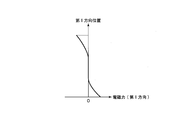
- FIG. 6 is a diagram showing the distribution in the first direction of the electromagnetic force in the first direction acting on the windings when energized.
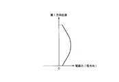
- FIG. 7 is a diagram showing a distribution in the first direction of the radial electromagnetic force acting on the windings when energized.
- the electromagnetic force in the first direction L1 acting on the winding 3 has the maximum absolute value at both ends of the winding 3 in the first direction L1, and zero at the center of the winding 3 in the first direction L1. It becomes.
- FIG. 6 is a diagram showing the distribution in the first direction of the electromagnetic force in the first direction acting on the windings when energized.
- the electromagnetic force in the first direction L1 acting on the winding 3 has the maximum absolute value at both ends of the winding 3 in the first direction L1, and zero at the center of the winding 3 in the first direction L1. It becomes.
- FIG. 6 is a diagram showing the distribution in the first direction of the electromagnetic force in the first direction acting on the windings when energized.
- the radial electromagnetic force acting on the winding 3 becomes maximum at the center portion of the winding 3 in the first direction L1 and becomes minimum at both ends of the winding 3 in the first direction L1. For this reason, the coil
- the winding 3 is fastened in the first direction L1 by the first yoke portion 22 and the second yoke portion 23 via the winding fastening member 11.
- the winding 3 is sandwiched between the upper iron core fastening member 10 ⁇ / b> A and the lower iron core fastening member 10 ⁇ / b> B via the winding fastening member 11. That is, a tightening force in the first direction L1 acts on the winding 3 from the first yoke portion 22, the second yoke portion 23, the upper iron core fastening member 10A, and the lower iron core fastening member 10B.
- the first yoke portion 22 and the second yoke portion 23 are connected by a leg portion 21 and a pair of connecting leg portions 24 that extend along the first direction L1.
- the upper iron core fastening member 10A is disposed so as to protrude from the first yoke portion 22 in the third direction L3. That is, the upper iron core fastening member 10 ⁇ / b> A is cantilevered by the first yoke portion 22.
- the lower iron core fastening member 10B is the same as the upper iron core fastening member 10A.
- the upper iron core fastening member 10A and the lower iron core fastening member 10B are more easily displaced in the first direction L1 than the first yoke portion 22 and the second yoke portion 23.
- the tightening force for tightening the winding 3 in the first direction L1 is greatest at a position overlapping the first yoke portion 22 and the second yoke portion 23 as viewed from the first direction L1.
- the tightening force for tightening the winding wire 3 in the first direction L1 is the smallest at a position farthest from the first yoke portion 22 and the second yoke portion 23 as viewed from the first direction L1.
- the tightening force for tightening the winding 3 in the first direction L1 gradually decreases as the distance from the same position as the first yoke portion 22 and the second yoke portion 23 in the circumferential direction increases.
- the tightening force for tightening the winding wire 3 in the first direction L1 is greatest at a position intersecting with a straight line passing through the winding axis O in the circumferential direction and extending along the third direction L3.
- the spacer unit 40 has a plurality of spacers 41a to 41l sandwiched between windings 3 (coils 31) adjacent in the first direction L1, and the amount of distortion with respect to the force in the first direction L1 differs in the circumferential direction.
- a configuration comprising according to this configuration, the spacer unit is configured so that the amount of distortion of the spacer unit 40 with respect to the force in the first direction L1 is relatively small at a position where the tightening force for tightening the winding 3 in the first direction L1 is relatively weak.
- the plurality of spacers 41a to 41l arranged side by side in the circumferential direction are made of different materials depending on the positions in the circumferential direction. For this reason, it is possible to easily form the spacer unit 40 in which the amount of distortion with respect to the force in the first direction L1 differs at the position in the circumferential direction.
- the tightening force for tightening the winding wire 3 in the first direction L1 gradually decreases as the distance from the first yoke portion 22 and the second yoke portion 23 increases in the circumferential direction.
- the high elastic spacers arranged at positions different from the first yoke part 22 and the second yoke part 23 in the circumferential direction are the first yoke part 22 and the second yoke part 23 in the circumferential direction rather than the high elastic spacer.
- a configuration is adopted in which the spring constant in the first direction L1 is larger than that of the low-elasticity spacer arranged at a position close to.
- the high elastic spacer having a larger spring constant than the low elastic spacer is disposed at a position where the tightening force for tightening the winding 3 in the first direction L1 is smaller than the position where the low elastic spacer is disposed in the circumferential direction. Since the high elastic spacer is less likely to be deformed (is less distorted) in the first direction L1 than the low elastic spacer, the vibration of the winding 3 can be regulated more than the low elastic spacer. As a result, the vibration in the first direction L1 of the winding 3 that increases as the tightening force of the winding 3 decreases can be efficiently suppressed.
- the highly elastic spacer intersects the position where the tightening force for tightening the winding 3 in the circumferential direction in the first direction L1, that is, the straight line extending along the third direction L3 through the winding axis O in the circumferential direction.
- a plurality are arranged around the position. For this reason, as compared with the configuration in which only one highly elastic spacer is disposed at a position where the tightening force for tightening the winding 3 in the first direction L1 is the smallest, the first of the winding 3 is wider in the circumferential direction. The vibration in the direction L1 can be efficiently suppressed.
- FIG. 8 is an explanatory diagram of the static induction electric device according to the second embodiment, and is a cross-sectional view of a portion corresponding to the line VV of FIG.
- the positions of the first yoke portion 22 and the second yoke portion 23 viewed from the first direction L1 are indicated by two-dot chain lines.
- the plurality of spacers 41a to 41l are formed in substantially the same shape.
- the second embodiment shown in FIG. 8 is different from the first embodiment in that the plurality of spacers 41a to 41l are formed so as to have different shapes depending on the positions where they are arranged.
- symbol is attached
- the stationary induction main body 4 of the stationary induction device 101 includes a spacer unit 140.
- the spacer unit 140 has a plurality (12 in this embodiment) of spacers 141a to 141l arranged between the coils.
- the plurality of spacers 141a to 141l are arranged in this order at an equal pitch in the circumferential direction.
- the spacers 141a and 141g are arranged at positions overlapping the first yoke portion 22 and the second yoke portion 23 when viewed from the first direction L1.
- the spacers 141a and 141g are arranged at linear positions extending along the second direction L2 through the winding axis O when viewed from the first direction L1.
- the spacers 141b to 141f and 141h to 141l are arranged at positions overlapping the upper iron core fastening member 10A and the lower iron core fastening member 10B (see FIGS. 1 to 3) when viewed from the first direction L1.
- the spacers 141d and 141j are arranged at positions on a straight line that extends along the third direction L3 through the winding axis O when viewed from the first direction L1. That is, the spacers 141d and 141j are arranged at positions farthest from the first yoke portion 22 and the second yoke portion 23 in the circumferential direction.
- the plurality of spacers 141a to 141l are made of an insulating material such as wood. Each of the spacers 141a to 141l is formed in a rectangular parallelepiped shape extending along both the first direction L1 and the radial direction.
- the spacers 141d, 141j (first spacers) and the spacers 141c, 141e, 141i, 141k (first spacers) adjacent to the spacers 141d, 141j in the circumferential direction are the other spacers 141a, 141b, 141f to 141h, 141l (
- the cross-sectional area of the cross section perpendicular to the first direction L1 is larger than that of the second spacer.
- the spacers 141c to 141e and 141i to 141k are arranged closer to the first yoke part 22 and the second yoke part 23 in the circumferential direction than the spacers 141c to 141e and 141i to 141k.
- the spring constant in the first direction L1 is larger than ⁇ 141h and 141l.
- the spacers 141c to 141e, 141i to 141k are referred to as “high elastic spacers”, and the spacers 141a, 141b, 141f to 141h, 141l are referred to as “low elastic spacers”.
- the spacer unit 140 includes the plurality of spacers 141a to 141l sandwiched between the coils, and the amount of distortion with respect to the force in the first direction L1 is different at the position in the circumferential direction. For this reason, it can suppress that the vibration of the winding 3 in the 1st direction L1 propagates to the container 5, and noise generate
- the high elastic spacers arranged at positions different from the first yoke part 22 and the second yoke part 23 in the circumferential direction are the first yoke part 22 and the second yoke in the circumferential direction rather than the high elastic spacers.
- a configuration in which the cross-sectional area of the cross section perpendicular to the first direction L1 is larger than that of the low-elasticity spacer disposed near the portion 23 is employed. That is, the high elastic spacer having a larger spring constant than the low elastic spacer is disposed at a position where the tightening force for tightening the winding 3 in the first direction L1 is smaller than the position where the low elastic spacer is disposed in the circumferential direction. As a result, the vibration in the first direction L1 of the winding 3 that increases as the tightening force of the winding 3 decreases can be efficiently suppressed.
- the high elastic spacer has a larger cross-sectional area perpendicular to the first direction L1 than the low elastic spacer. For this reason, compared with the case where all the spacers have the same cross-sectional area as a low elastic spacer, the contact area and frictional force of a spacer and the coil 31 (winding 3) increase. Thereby, the relative displacement between the coils 31 and the radial vibration of the winding 3 can be reduced.
- FIG. 9 is an explanatory diagram of the static induction electric device according to the third embodiment, and is a cross-sectional view of a portion corresponding to the line VV of FIG.
- the positions of the first yoke portion 22 and the second yoke portion 23 viewed from the first direction L1 are indicated by two-dot chain lines.
- the plurality of spacers 41a to 41l are formed in substantially the same shape.
- the plurality of spacers 141a to 141l are made of different materials.
- the plurality of spacers 241a to 241l are different from the first embodiment in that the material and the shape are different depending on the arranged positions. Yes.
- the stationary induction main body 4 of the stationary induction device 201 includes a spacer unit 240.
- the spacer unit 240 has a plurality (12 in this embodiment) of spacers 241a to 241l arranged between the coils.
- the plurality of spacers 241a to 241l are arranged in this order at an equal pitch in the circumferential direction.
- the spacers 241a and 241g are arranged at positions overlapping the first yoke portion 22 and the second yoke portion 23 when viewed from the first direction L1.
- the spacers 241a and 241g are arranged at linear positions extending along the second direction L2 through the winding axis O as viewed from the first direction L1.
- the spacers 241b to 241f and 241h to 241l are disposed at positions overlapping the upper iron core fastening member 10A and the lower iron core fastening member 10B (see FIGS. 1 to 3) when viewed from the first direction L1.
- the spacers 241d and 241j are arranged at linear positions extending along the third direction L3 through the winding axis O when viewed from the first direction L1. That is, the spacers 241d and 241j are arranged at positions farthest from the first yoke portion 22 and the second yoke portion 23 in the circumferential direction.
- the plurality of spacers 241a to 241l are made of an insulating material such as wood. Each of the spacers 241a to 241l is formed in a rectangular parallelepiped shape extending in both the first direction L1 and the radial direction.
- the spacers 241d, 241j and the spacers 241c, 241e, 241i, 241k (first spacers) adjacent to the spacers 241d, 241j (first spacer) in the circumferential direction are the other spacers 241a, 241b, 241f to 241h, 241l (
- the cross-sectional area of the cross section perpendicular to the first direction L1 is larger than that of the second spacer.
- the spacers 241c to 241e and 241i to 241k are formed of a material having a higher Young's modulus than the other spacers 241a, 241b, 241f to 241h, and 241l.
- the spacers 241c to 241e and 241i to 241k are arranged closer to the first yoke portion 22 and the second yoke portion 23 in the circumferential direction than the spacers 241c to 241e and 241i to 241k.
- the spring constant in the first direction L1 is larger than ⁇ 241h and 241l.
- the spacer unit 240 is formed so that the distortion amount with respect to the force in the first direction L1 acting via the winding 3 is different in the circumferential direction.
- the spacers 241c to 241e and 241i to 241k are referred to as “high elastic spacers”
- the spacers 241a, 241b, 241f to 241h, and 241l are referred to as “low elastic spacers”.
- the spacer unit 240 includes the plurality of spacers 241a to 241l sandwiched between the coils, and the amount of distortion with respect to the force in the first direction L1 is different at the position in the circumferential direction. For this reason, it can suppress that the vibration of the coil
- the high elastic spacers arranged at positions different from the first yoke part 22 and the second yoke part 23 in the circumferential direction are the first yoke part 22 and the second yoke in the circumferential direction rather than the high elastic spacers.
- a configuration in which the cross-sectional area of the cross section perpendicular to the first direction L1 is larger than that of the low-elasticity spacer disposed near the portion 23 is employed. That is, the high elastic spacer having a larger spring constant than the low elastic spacer is disposed at a position where the tightening force for tightening the winding 3 in the first direction L1 is smaller than the position where the low elastic spacer is disposed in the circumferential direction. As a result, the vibration in the first direction L1 of the winding 3 that increases as the tightening force of the winding 3 decreases can be efficiently suppressed.
- FIG. 10 is an explanatory diagram of the static induction electric device according to the fourth embodiment, and is a cross-sectional view of a portion corresponding to the line VV of FIG.
- the positions of the first yoke portion 22 and the second yoke portion 23 viewed from the first direction L1 are indicated by a two-dot chain line.
- the plurality of spacers 241a to 241l are formed of two kinds of materials.
- the fourth embodiment shown in FIG. 10 differs from the third embodiment in that the plurality of spacers 341a to 341l are formed of three kinds of materials.
- the stationary induction main body 4 of the stationary induction device 301 includes a spacer unit 340.
- the spacer unit 340 includes a plurality (12 in this embodiment) of spacers 341a to 341l arranged between the coils.
- the plurality of spacers 341a to 341l are arranged in this order along the circumferential direction at an equal pitch.
- the spacers 341a and 341g are arranged at positions overlapping the first yoke portion 22 and the second yoke portion 23 when viewed from the first direction L1.
- the spacers 341a and 341g are disposed at linear positions extending along the second direction L2 through the winding axis O when viewed from the first direction L1.
- the spacers 341b to 341f and 341h to 341l are arranged at positions overlapping the upper iron core fastening member 10A and the lower iron core fastening member 10B (see FIGS. 1 to 3) when viewed from the first direction L1.
- the spacers 341d and 341j are arranged at linear positions extending along the third direction L3 through the winding axis O when viewed from the first direction L1. That is, the spacers 341d and 341j are arranged at positions farthest from the first yoke portion 22 and the second yoke portion 23 in the circumferential direction.
- the plurality of spacers 341a to 341l are formed of an insulating material such as wood.
- Each of the spacers 341a to 341l is formed in a rectangular parallelepiped shape extending along both the first direction L1 and the radial direction.
- the spacers 341d and 341j (first spacers) have a larger cross-sectional area perpendicular to the first direction L1 than the other spacers 341a to 341c, 341e to 341i, 341k, and 341l.
- the spacers 341d and 341j are formed of a material having a higher Young's modulus than the other spacers 341a to 341c, 341e to 341i, 341k, and 341l.
- the spacers 341d and 341j are more than spacers 341a to 341c, 341e to 341i, 341k, and 341l disposed closer to the first yoke portion 22 and the second yoke portion 23 in the circumferential direction than the spacers 341d and 341j.
- the spring constant in the first direction L1 is large.
- the spacers 341c, 341e, 341i, 341k that are adjacent to the spacers 341d, 341j in the circumferential direction are disposed closer to the first yoke portion 22 and the second yoke portion 23 in the circumferential direction than the spacers 341c, 341e, 341i, 341k.
- the spacers 341a, 341b, 341f to 341h, 341l (second spacer) are made of a material having a higher Young's modulus.
- the spacers 341c, 341e, 341i, and 341k are arranged closer to the first yoke portion 22 and the second yoke portion 23 in the circumferential direction than the spacers 341c, 341e, 341i, and 341k.
- the spring constant in the first direction L1 is larger than ⁇ 341h and 341l. Therefore, as the distance from the first yoke portion 22 and the second yoke portion 23 in the circumferential direction increases, the spring constant increases in two stages.
- the spacer unit 340 is formed such that the amount of distortion with respect to the force in the first direction L1 acting via the winding 3 is different in the circumferential direction.
- the spacer unit 340 includes the plurality of spacers 341a to 341l sandwiched between the coils, and the amount of distortion with respect to the force in the first direction L1 varies depending on the position in the circumferential direction. For this reason, it can suppress that the vibration of the coil
- the spring constants of the spacers 341a to 341l in the first direction L1 increase in two stages.
- the amount of distortion with respect to the force in the first direction L1 of the spacer unit 340 is further increased according to the tightening force of the winding 3.
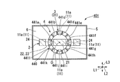
- FIG. 11 is an explanatory diagram of the static induction electric device according to the fifth embodiment, and is a cross-sectional view of a portion corresponding to the line VV of FIG.
- the positions of the block 11a, the first yoke portion 22, and the second yoke portion 23 of the winding fastening member 11 as viewed from the first direction L1 are indicated by two-dot chain lines.
- the spacers 41a, 41d, 41g, 41j are arranged at the same position as the block 11a of the winding fastening member 11 in the circumferential direction.
- the plurality of spacers 441a to 441l are arranged in positions different from the block 11a of the winding fastening member 11 in the circumferential direction. It is different from the embodiment.
- the stationary induction main body 4 of the stationary induction device 401 includes a spacer unit 440.
- the spacer unit 440 includes a plurality (12 in this embodiment) of spacers 441a to 441l disposed between the coils.
- the plurality of spacers 441a to 441l are arranged in this order along the circumferential direction at an equal pitch.
- the plurality of spacers 441a to 441l are arranged at positions that do not overlap the block 11a of the winding fastening member 11 when viewed from the first direction L1. That is, the plurality of spacers 441a to 441l are arranged at positions different from the contact point between the winding 3 and the block 11a in the circumferential direction.
- At least a part of each of the spacers 441a, 441f, 441g, 441l is disposed at a position overlapping the first yoke portion 22 and the second yoke portion 23 when viewed from the first direction L1.
- the spacers 441b to 441e and 441h to 441k are arranged at positions overlapping the upper iron core fastening member 10A and the lower iron core fastening member 10B when viewed from the first direction L1.
- the plurality of spacers 441a to 441l are formed in substantially the same shape by an insulating material such as wood.
- spacers 441c, 441d, 441i, 441j first spacers, high elastic spacers
- the spacers 441c, 441d, 441i, 441j are disposed closer to the first yoke portion 22 and the second yoke portion 23 in the circumferential direction than the spacers 441c, 441d, 441i, 441j.
- the spring constant in the first direction is larger than ⁇ 441h, 441k, 441l.
- the spacer unit 440 includes the plurality of spacers 441a to 441l sandwiched between the coils, and the amount of distortion with respect to the force in the first direction L1 is different at the position in the circumferential direction. For this reason, it can suppress that the vibration of the coil
- the tightening force for fastening the winding 3 in the first direction L1 is the winding 3 in the circumferential direction.
- the block 11a may be concentrated at the position of the contact portion. In this case, there is a possibility that the tightening force of the winding 3 is reduced at a position other than the contact point between the winding 3 and the block 11a in the circumferential direction, and the vibration of the winding 3 in the first direction L1 is increased. is there.
- a configuration is adopted in which the plurality of spacers 441a to 441l are arranged at positions different from the contact points between the winding 3 and the block 11a in the circumferential direction.
- the winding tightening member 11 has a plurality of blocks 11a so as to intermittently contact the winding 3 in the circumferential direction.
- the present invention is not limited to this, and the winding fastening member is formed in an annular shape corresponding to the shape of the winding 3 viewed from the first direction L1 so as to continuously contact the winding 3 in the circumferential direction. May be.
- the spacer units 40, 140, 240, 340, 440 are arranged between all the coils, but the present invention is not limited to this.
- the spacer unit may be disposed between at least one coil.
- the container 5 is filled with the insulating oil 6 as an insulating medium for insulation and cooling.
- the present invention is not limited to this, and an insulating liquid or gas is used as the insulating medium. Can do.
- the spacer units 40, 140, 240, 340, and 440 have twelve spacers.
- the present invention is not limited to this, and the number of spacers can be set arbitrarily.
- the plurality of spacers are not necessarily arranged at an equal pitch.
- spacers formed of substantially the same shape and the same material are arranged side by side in the circumferential direction, as the distance from the first yoke portion 22 and the second yoke portion 23 in the circumferential direction increases, the distance between adjacent spacers increases. It may be narrowed. Thereby, the distortion amount with respect to the force of the spacer unit in the first direction L1 can be changed depending on the position in the circumferential direction.
- the spacer is formed in the rectangular parallelepiped shape, it is not limited to this, It can set to arbitrary shapes.
- the spring constant in the first direction L1 of the spacer is set so as to be maximized in the spacer disposed at the position where the tightening force of the winding 3 in the circumferential direction is the smallest. It is not limited to this.
- the spring constant of the spacer in the first direction L1 may be set so as to be maximized, for example, in a spacer disposed at a circumferential position that becomes an antinode of vibration of the winding 3 in the first direction L1.
- a spacer unit having a plurality of spacers sandwiched between adjacent windings in the first direction and having different strain amounts with respect to the force in the first direction in the circumferential direction.
- the spacer unit is provided so that the amount of distortion with respect to the force in the first direction of the spacer unit is relatively small at a position where the tightening force for tightening the winding in the first direction is relatively weak.
- the vibration in the first direction of the winding can be suppressed from becoming relatively large. Therefore, it can suppress that the vibration of the winding in the first direction propagates to the container and becomes noise.
Landscapes
- Engineering & Computer Science (AREA)
- Power Engineering (AREA)
- Regulation Of General Use Transformers (AREA)
Abstract
実施形態の静止誘導電器は、鉄心と、巻線と、容器と、スペーサユニットと、を持つ。鉄心は、脚部および一対のヨーク部を持つ。脚部は、第1方向に沿って延びる。一対のヨーク部は、脚部の両端部から第1方向に交差する第2方向に沿って延びる。巻線は、脚部に巻回され、一対のヨーク部により第1方向に締め付けられている。容器は、鉄心および巻線を収容する。スペーサユニットは、複数のスペーサを持つ。複数のスペーサは、第1方向で隣り合う巻線に挟まれている。複数のスペーサは、巻線の巻回軸回りの周方向に並んで配置されている。スペーサユニットは、第1方向の力に対する歪み量が周方向における位置で異なる。
Description
本発明の実施形態は、静止誘導電器に関する。
一般に、変圧器やリアクトル等の静止誘導電器は、巻線や鉄心等により構成された静止誘導電器本体と、静止誘導電器本体を収容する容器と、容器内に充填された絶縁用および冷却用の冷却媒体と、を備える。静止誘導電器は、巻線への通電により発生する巻線の振動が、静止誘導電器本体と容器との接続部や冷却媒体等を介して容器の壁に伝わることにより、騒音を発生させる場合がある。特に近年では、静止誘導電器は、大容量化や小型化、軽量化等により、大きな電界エネルギーや磁界エネルギーが小さな空間に閉じ込められる構造になっており、振動および騒音が大きくなる傾向がある。
本発明が解決しようとする課題は、通電時の騒音を抑制できる静止誘導電器を提供することである。
実施形態の静止誘導電器は、鉄心と、巻線と、容器と、スペーサユニットと、を持つ。鉄心は、脚部および一対のヨーク部を持つ。脚部は、第1方向に沿って延びる。一対のヨーク部は、脚部の両端部から第1方向に交差する第2方向に沿って延びる。巻線は、脚部に巻回され、一対のヨーク部により第1方向に締め付けられている。容器は、鉄心および巻線を収容する。スペーサユニットは、複数のスペーサを持つ。複数のスペーサは、第1方向で隣り合う巻線に挟まれている。複数のスペーサは、巻線の巻回軸回りの周方向に並んで配置されている。スペーサユニットは、第1方向の力に対する歪み量が周方向における位置で異なる。
以下、実施形態の静止誘導電器を、図面を参照して説明する。
(第1の実施形態)
図1は、第1の実施形態に係る静止誘導電器の正面断面図である。
図1に示すように、静止誘導電器1は、鉄心2および巻線3を有する静止誘導電器本体4と、静止誘導電器本体4を収容する容器5と、容器5内に充填された絶縁用かつ冷却用の絶縁油6と、を備えている。
図1は、第1の実施形態に係る静止誘導電器の正面断面図である。
図1に示すように、静止誘導電器1は、鉄心2および巻線3を有する静止誘導電器本体4と、静止誘導電器本体4を収容する容器5と、容器5内に充填された絶縁用かつ冷却用の絶縁油6と、を備えている。
図2は、第1の実施形態に係る静止誘導電器の側面断面図である。図3は、図1のIII-III線における断面図である。
図1から図3に示すように、容器5は、直方体状に形成されている。容器5は、例えばステンレス鋼等により形成されている。容器5の側壁は、鉛直方向に沿って延びている。容器5の天壁は、水平方向に沿って延びている。容器5の底板上には、静止誘導電器本体4が固定されている。
図1から図3に示すように、容器5は、直方体状に形成されている。容器5は、例えばステンレス鋼等により形成されている。容器5の側壁は、鉛直方向に沿って延びている。容器5の天壁は、水平方向に沿って延びている。容器5の底板上には、静止誘導電器本体4が固定されている。
図1および図2に示すように、鉄心2は、鉛直方向に沿う第1方向L1に沿って延びる脚部21と、脚部21の上端部に接続する中央部を有するとともに脚部21の上端部から第1方向L1に直交する第2方向L2に沿って延びる第1ヨーク部22と、脚部21の下端部に接続する中央部を有するとともに脚部21の下端部から第2方向L2に沿って延びる第2ヨーク部23と、第1ヨーク部22の先端部と第2ヨーク部23の先端部とを連結する一対の連結脚部24と、を備えている。鉄心2は、複数の電磁鋼板を第1方向L1および第2方向L2に直交する第3方向L3に積層することにより形成されている。複数の電磁鋼板は、鉄心2の上端部を第3方向L3の両側から挟み込む上側鉄心締付部材10Aと、鉄心2の下端部を第3方向L3の両側から挟み込む下側鉄心締付部材10Bと、により支持されている。
図2および図3に示すように、上側鉄心締付部材10Aは、第2方向L2に沿って延びている。上側鉄心締付部材10Aの下面は、第2方向L2および第3方向L3の双方向に沿って延びている。下側鉄心締付部材10Bは、第2方向L2に沿って延びている。下側鉄心締付部材10Bの上面は、第2方向L2および第3方向L3の双方向に沿って延びている。
巻線3は、鉄心2の脚部21に円筒状に巻回されている。巻線3の巻回軸Oは、第1方向L1に沿って延びている。巻線3は、第1方向L1に積層された複数のコイル31を形成している。巻線3は、鉄心2の脚部21に対して隙間を有している。巻線3と脚部21との間には、巻線3と脚部21との隙間を保持する部材が配置されていてもよい。巻線3は、巻線締付部材11を介して、第1ヨーク部22および第2ヨーク部23により第1方向L1に締め付けられている。また、巻線3は、巻線締付部材11を介して、上側鉄心締付部材10Aの下面、および下側鉄心締付部材10Bの上面に挟み込まれている。なお、以下の説明では、巻線3の巻回軸O回りの周方向を単に「周方向」といい、第1方向L1に直交して巻回軸Oから放射状に延びる方向を「径方向」という。
巻線締付部材11は、第1方向L1における第1ヨーク部22と巻線3との間、および第2ヨーク部23と巻線3との間に配置されている。巻線3の上側に配置された巻線締付部材11は、周方向に略90°ピッチで配置された複数のブロック11aを有する。巻線3の上側に配置された巻線締付部材11は、巻線3に対して周方向で間欠的に接触している。ブロック11aは、例えば木材等の絶縁材料により形成されている。複数のブロック11aは、巻線3と第1ヨーク部22との間、および巻線3と上側鉄心締付部材10Aとの間に配置されている。具体的に、複数のブロック11aは、第1方向L1から見て巻回軸Oを通り第2方向L2に沿って延びる直線上の位置、および巻回軸Oを通り第3方向L3に沿って延びる直線上の位置に配置されている。下側鉄心締付部材10Bについても、上側鉄心締付部材10Aと同様である。
図4は、図1のIV部拡大図である。図5は、図1のV-V線における断面図である。なお、図5では、第1方向L1から見た第1ヨーク部22および第2ヨーク部23の位置を2点鎖線で示している。
図4および図5に示すように、静止誘導電器本体4は、スペーサユニット40をさらに備えている。スペーサユニット40は、複数(本実施形態では12個)のスペーサ41a~41lを有する。複数のスペーサ41a~41lは、第1方向L1で隣り合う一対のコイル31(巻線3)の間(以下、「コイル間」という。)に配置されている。複数のスペーサ41a~41lは、隣り合う一対のコイル31(巻線3)に挟まれることで、一対のコイル31の間に保持されている。スペーサユニット40は、例えば全てのコイル間に配置されている。
図4および図5に示すように、静止誘導電器本体4は、スペーサユニット40をさらに備えている。スペーサユニット40は、複数(本実施形態では12個)のスペーサ41a~41lを有する。複数のスペーサ41a~41lは、第1方向L1で隣り合う一対のコイル31(巻線3)の間(以下、「コイル間」という。)に配置されている。複数のスペーサ41a~41lは、隣り合う一対のコイル31(巻線3)に挟まれることで、一対のコイル31の間に保持されている。スペーサユニット40は、例えば全てのコイル間に配置されている。
図5に示すように、複数のスペーサ41a~41lは、この順で周方向に等ピッチで並んで配置されている。スペーサ41a,41gは、第1方向L1から見て第1ヨーク部22および第2ヨーク部23と重なる位置に配置されている。スペーサ41a,41gは、第1方向L1から見て巻回軸Oを通り第2方向L2に沿って延びる直線上の位置に配置されている。スペーサ41b~41f,41h~41lは、第1方向L1から見て上側鉄心締付部材10Aおよび下側鉄心締付部材10B(図1から図3参照)と重なる位置に配置されている。スペーサ41d,41jは、第1方向L1から見て巻回軸Oを通り第3方向L3に沿って延びる直線上の位置に配置されている。すなわち、スペーサ41d,41jは、周方向において第1ヨーク部22および第2ヨーク部23から最も離れた位置に配置されている。
複数のスペーサ41a~41lは、絶縁材料により略同形に形成されている。複数のスペーサ41a~41lを形成する材料としては、例えば木材が好適である。各スペーサ41a~41lは、第1方向L1および径方向の双方向に沿って延びる直方体状に形成されている。スペーサ41a~41lは、周方向の位置によって、異なる材質を有する材料により形成されている。スペーサ41d,41j(第1スペーサ)、およびこれらスペーサ41d,41jと周方向で隣り合うスペーサ41c,41e,41i,41k(第1スペーサ)は、他のスペーサ41a,41b,41f~41h,41l(第2スペーサ)よりもヤング率の高い材料により形成されている。これにより、スペーサ41c~41e,41i~41kは、スペーサ41c~41e,41i~41kよりも周方向において第1ヨーク部22および第2ヨーク部23に近い位置に配置されたスペーサ41a,41b,41f~41h,41lよりも第1方向L1のばね定数が大きい。これにより、スペーサユニット40は、巻線3を介して作用する第1方向L1の力に対する歪み量が周方向における位置で異なるように形成されている。
なお、第1方向L1のばね定数とは、第1方向L1の力を加えた際の荷重を第1方向L1における変位量で割った定数である。また、第1方向L1の力に対する歪み量とは、所定の大きさの力を第1方向L1に沿って加えた場合の垂直歪みを意味する。本実施形態の以下の説明では、スペーサ41c~41e,41i~41kを「高弾性スペーサ」と称し、スペーサ41a,41b,41f~41h,41lを「低弾性スペーサ」と称する。
ここで、図6および図7を参照して、通電時に巻線3に働く電磁力について説明する。
図6は、通電時に巻線に働く第1方向の電磁力の第1方向における分布を示す図である。図7は、通電時に巻線に働く径方向の電磁力の第1方向における分布を示す図である。
図6によれば、巻線3に働く第1方向L1の電磁力は、巻線3の第1方向L1両端部において絶対値が最大となり、巻線3の第1方向L1の中央部ではゼロとなる。図7によれば、巻線3に働く径方向の電磁力は、巻線3の第1方向L1の中央部において最大となり、巻線3の第1方向L1両端部において最小となる。このため、巻線3は、交流通電時に第1方向L1および径方向の双方向に振動する。巻線3の振動は、容器5内に充填された絶縁油6を伝播して容器5の壁を振動させ、騒音を発生させる。
図6は、通電時に巻線に働く第1方向の電磁力の第1方向における分布を示す図である。図7は、通電時に巻線に働く径方向の電磁力の第1方向における分布を示す図である。
図6によれば、巻線3に働く第1方向L1の電磁力は、巻線3の第1方向L1両端部において絶対値が最大となり、巻線3の第1方向L1の中央部ではゼロとなる。図7によれば、巻線3に働く径方向の電磁力は、巻線3の第1方向L1の中央部において最大となり、巻線3の第1方向L1両端部において最小となる。このため、巻線3は、交流通電時に第1方向L1および径方向の双方向に振動する。巻線3の振動は、容器5内に充填された絶縁油6を伝播して容器5の壁を振動させ、騒音を発生させる。
以下、本実施形態の作用について説明する。
巻線3は、巻線締付部材11を介して、第1ヨーク部22および第2ヨーク部23により第1方向L1に締め付けられている。また、巻線3は、巻線締付部材11を介して、上側鉄心締付部材10Aおよび下側鉄心締付部材10Bに挟み込まれている。すなわち、巻線3には、第1ヨーク部22、第2ヨーク部23、上側鉄心締付部材10Aおよび下側鉄心締付部材10Bから、第1方向L1の締付力が作用している。
巻線3は、巻線締付部材11を介して、第1ヨーク部22および第2ヨーク部23により第1方向L1に締め付けられている。また、巻線3は、巻線締付部材11を介して、上側鉄心締付部材10Aおよび下側鉄心締付部材10Bに挟み込まれている。すなわち、巻線3には、第1ヨーク部22、第2ヨーク部23、上側鉄心締付部材10Aおよび下側鉄心締付部材10Bから、第1方向L1の締付力が作用している。
第1ヨーク部22および第2ヨーク部23は、第1方向L1に沿って延びる脚部21および一対の連結脚部24により連結されている。これに対して、上側鉄心締付部材10Aは、第1ヨーク部22から第3方向L3に突出するように配置されている。すなわち、上側鉄心締付部材10Aは、第1ヨーク部22に片持ち支持された状態となっている。下側鉄心締付部材10Bについても、上側鉄心締付部材10Aと同様である。このため、上側鉄心締付部材10Aおよび下側鉄心締付部材10Bは、第1ヨーク部22および第2ヨーク部23に比べて第1方向L1に変位しやすくなっている。その結果、巻線3を第1方向L1に締め付ける締付力は、第1方向L1から見て第1ヨーク部22および第2ヨーク部23と重なる位置において最も大きい。また、巻線3を第1方向L1に締め付ける締付力は、第1方向L1から見て第1ヨーク部22および第2ヨーク部23から最も離れた位置において最も小さい。つまり、巻線3を第1方向L1に締め付ける締付力は、周方向における第1ヨーク部22および第2ヨーク部23と同じ位置から離れるに従い徐々に小さくなる。本実施形態では、巻線3を第1方向L1に締め付ける締付力は、周方向における巻回軸Oを通り第3方向L3に沿って延びる直線と交差する位置において最も大きくなる。
本実施形態では、第1方向L1で隣り合う巻線3(コイル31)に挟まれた複数のスペーサ41a~41lを有するとともに、第1方向L1の力に対する歪み量が周方向で異なるスペーサユニット40を備える構成を採用した。この構成によれば、巻線3を第1方向L1に締め付ける締付力が相対的に弱い位置において、スペーサユニット40の第1方向L1の力に対する歪み量が相対的に小さくなるようにスペーサユニット40を設けることで、巻線3の第1方向L1の振動が相対的に大きくなることを抑制できる。したがって、巻線3の第1方向L1の振動が容器5に伝播して騒音が発生することを抑制できる。
しかも、周方向に並んで配置された複数のスペーサ41a~41lは、周方向の位置によって異なる材料により形成されている。このため、第1方向L1の力に対する歪み量が周方向における位置で異なるスペーサユニット40を容易に形成することができる。
ところで、上述したように、巻線3を第1方向L1に締め付ける締付力は、周方向において第1ヨーク部22および第2ヨーク部23から離れるに従い徐々に小さくなる。
本実施形態では、周方向における第1ヨーク部22および第2ヨーク部23と異なる位置に配置された高弾性スペーサは、高弾性スペーサよりも周方向における第1ヨーク部22および第2ヨーク部23に近い位置に配置された低弾性スペーサよりも第1方向L1のばね定数が大きい構成を採用した。すなわち、周方向における低弾性スペーサが配置された位置よりも、巻線3を第1方向L1に締め付ける締付力が小さい位置に、低弾性スペーサよりもばね定数の大きい高弾性スペーサを配置した。高弾性スペーサは、低弾性スペーサよりも第1方向L1に変形しにくい(歪みにくい)ので、低弾性スペーサよりも巻線3の振動を規制できる。これにより、巻線3の締付力が小さくなるに従い大きくなる巻線3の第1方向L1の振動を効率よく抑制することができる。
本実施形態では、周方向における第1ヨーク部22および第2ヨーク部23と異なる位置に配置された高弾性スペーサは、高弾性スペーサよりも周方向における第1ヨーク部22および第2ヨーク部23に近い位置に配置された低弾性スペーサよりも第1方向L1のばね定数が大きい構成を採用した。すなわち、周方向における低弾性スペーサが配置された位置よりも、巻線3を第1方向L1に締め付ける締付力が小さい位置に、低弾性スペーサよりもばね定数の大きい高弾性スペーサを配置した。高弾性スペーサは、低弾性スペーサよりも第1方向L1に変形しにくい(歪みにくい)ので、低弾性スペーサよりも巻線3の振動を規制できる。これにより、巻線3の締付力が小さくなるに従い大きくなる巻線3の第1方向L1の振動を効率よく抑制することができる。
また、高弾性スペーサは、周方向における巻線3を第1方向L1に締め付ける締付力が最も小さい位置、すなわち周方向における巻回軸Oを通り第3方向L3に沿って延びる直線と交差する位置を中心に複数配置されている。このため、巻線3を第1方向L1に締め付ける締付力が最も小さい位置に高弾性スペーサが1個だけ配置される構成と比較して、周方向におけるより広い領域で巻線3の第1方向L1の振動を効率よく抑制することができる。
(第2の実施形態)
図8は、第2の実施形態に係る静止誘導電器の説明図であって、図1のV-V線に相当する部分における断面図である。なお、図8では、第1方向L1から見た第1ヨーク部22および第2ヨーク部23の位置を2点鎖線で示している。
図1から図5に示す第1の実施形態では、複数のスペーサ41a~41lは、略同形に形成されている。これに対して図8に示す第2の実施形態では、複数のスペーサ41a~41lは、配置された位置によって形状が異なるように形成されている点で、第1の実施形態と異なっている。なお、図1から図5に示す第1の実施形態と同様の構成については、同一符号を付して詳細な説明を省略する(以下の実施形態についても同様)。
図8は、第2の実施形態に係る静止誘導電器の説明図であって、図1のV-V線に相当する部分における断面図である。なお、図8では、第1方向L1から見た第1ヨーク部22および第2ヨーク部23の位置を2点鎖線で示している。
図1から図5に示す第1の実施形態では、複数のスペーサ41a~41lは、略同形に形成されている。これに対して図8に示す第2の実施形態では、複数のスペーサ41a~41lは、配置された位置によって形状が異なるように形成されている点で、第1の実施形態と異なっている。なお、図1から図5に示す第1の実施形態と同様の構成については、同一符号を付して詳細な説明を省略する(以下の実施形態についても同様)。
図8に示すように、静止誘導電器101の静止誘導電器本体4は、スペーサユニット140を備えている。スペーサユニット140は、コイル間に配置された複数(本実施形態では12個)のスペーサ141a~141lを有する。
複数のスペーサ141a~141lは、この順で周方向に等ピッチで並んで配置されている。スペーサ141a,141gは、第1方向L1から見て第1ヨーク部22および第2ヨーク部23と重なる位置に配置されている。スペーサ141a,141gは、第1方向L1から見て巻回軸Oを通り第2方向L2に沿って延びる直線上の位置に配置されている。スペーサ141b~141f,141h~141lは、第1方向L1から見て上側鉄心締付部材10Aおよび下側鉄心締付部材10B(図1から図3参照)と重なる位置に配置されている。スペーサ141d,141jは、第1方向L1から見て巻回軸Oを通り第3方向L3に沿って延びる直線上の位置に配置されている。すなわち、スペーサ141d,141jは、周方向において第1ヨーク部22および第2ヨーク部23から最も離れた位置に配置されている。
複数のスペーサ141a~141lは、例えば木材等の絶縁材料により形成されている。各スペーサ141a~141lは、第1方向L1および径方向の双方向に沿って延びる直方体状に形成されている。スペーサ141d,141j(第1スペーサ)、およびこれらスペーサ141d,141jと周方向で隣り合うスペーサ141c,141e,141i,141k(第1スペーサ)は、他のスペーサ141a,141b,141f~141h,141l(第2スペーサ)よりも第1方向L1に直交する断面の断面積が大きい。これにより、スペーサ141c~141e,141i~141kは、スペーサ141c~141e,141i~141kよりも周方向において第1ヨーク部22および第2ヨーク部23に近い位置に配置されたスペーサ141a,141b,141f~141h,141lよりも第1方向L1のばね定数が大きい。これにより、スペーサユニット140は、巻線3を介して作用する第1方向L1の力に対する歪み量が周方向における位置で異なるように形成されている。本実施形態の以下の説明では、スペーサ141c~141e,141i~141kを「高弾性スペーサ」と称し、スペーサ141a,141b,141f~141h,141lを「低弾性スペーサ」と称する。
このように、本実施形態によれば、コイル間に挟まれた複数のスペーサ141a~141lを有するとともに、第1方向L1の力に対する歪み量が周方向における位置で異なるスペーサユニット140を備える。このため、上述した第1の実施形態と同様に、巻線3の第1方向L1の振動が容器5に伝播して騒音が発生することを抑制できる。
また、本実施形態では、周方向における第1ヨーク部22および第2ヨーク部23と異なる位置に配置された高弾性スペーサは、高弾性スペーサよりも周方向における第1ヨーク部22および第2ヨーク部23に近い位置に配置された低弾性スペーサよりも、第1方向L1に直交する断面の断面積が大きい構成を採用した。すなわち、周方向における低弾性スペーサが配置された位置よりも、巻線3を第1方向L1に締め付ける締付力が小さい位置に、低弾性スペーサよりもばね定数の大きい高弾性スペーサを配置した。これにより、巻線3の締付力が小さくなるに従い大きくなる巻線3の第1方向L1の振動を効率よく抑制することができる。
また、高弾性スペーサは、低弾性スペーサよりも、第1方向L1に直交する断面の断面積が大きい。このため、全てのスペーサが低弾性スペーサと同等の断面積を有する場合と比較して、スペーサとコイル31(巻線3)との接触面積および摩擦力が増加する。これにより、コイル31間の相対変位、および巻線3の径方向の振動を低減させることができる。
(第3の実施形態)
図9は、第3の実施形態に係る静止誘導電器の説明図であって、図1のV-V線に相当する部分における断面図である。なお、図9では、第1方向L1から見た第1ヨーク部22および第2ヨーク部23の位置を2点鎖線で示している。
図1から図5に示す第1の実施形態では、複数のスペーサ41a~41lは、略同形に形成されている。また、図8に示す第2の実施形態では、複数のスペーサ141a~141lは、異なる材料により形成されている。これに対して図9に示す第3の実施形態では、複数のスペーサ241a~241lは、配置された位置によって材料および形状が異なるように形成されている点で、第1の実施形態と異なっている。
図9は、第3の実施形態に係る静止誘導電器の説明図であって、図1のV-V線に相当する部分における断面図である。なお、図9では、第1方向L1から見た第1ヨーク部22および第2ヨーク部23の位置を2点鎖線で示している。
図1から図5に示す第1の実施形態では、複数のスペーサ41a~41lは、略同形に形成されている。また、図8に示す第2の実施形態では、複数のスペーサ141a~141lは、異なる材料により形成されている。これに対して図9に示す第3の実施形態では、複数のスペーサ241a~241lは、配置された位置によって材料および形状が異なるように形成されている点で、第1の実施形態と異なっている。
図9に示すように、静止誘導電器201の静止誘導電器本体4は、スペーサユニット240を備えている。スペーサユニット240は、コイル間に配置された複数(本実施形態では12個)のスペーサ241a~241lを有する。
複数のスペーサ241a~241lは、この順で周方向に等ピッチで並んで配置されている。スペーサ241a,241gは、第1方向L1から見て第1ヨーク部22および第2ヨーク部23と重なる位置に配置されている。スペーサ241a,241gは、第1方向L1から見て巻回軸Oを通り第2方向L2に沿って延びる直線上の位置に配置されている。スペーサ241b~241f,241h~241lは、第1方向L1から見て上側鉄心締付部材10Aおよび下側鉄心締付部材10B(図1から図3参照)と重なる位置に配置されている。スペーサ241d,241jは、第1方向L1から見て巻回軸Oを通り第3方向L3に沿って延びる直線上の位置に配置されている。すなわち、スペーサ241d,241jは、周方向において第1ヨーク部22および第2ヨーク部23から最も離れた位置に配置されている。
複数のスペーサ241a~241lは、例えば木材等の絶縁材料により形成されている。各スペーサ241a~241lは、第1方向L1および径方向の双方向に沿って延びる直方体状に形成されている。スペーサ241d,241j、およびこれらスペーサ241d,241j(第1スペーサ)と周方向で隣り合うスペーサ241c,241e,241i,241k(第1スペーサ)は、他のスペーサ241a,241b,241f~241h,241l(第2スペーサ)よりも第1方向L1に直交する断面の断面積が大きい。また、スペーサ241c~241e,241i~241kは、他のスペーサ241a,241b,241f~241h,241lよりもヤング率の高い材料により形成されている。これにより、スペーサ241c~241e,241i~241kは、スペーサ241c~241e,241i~241kよりも周方向において第1ヨーク部22および第2ヨーク部23に近い位置に配置されたスペーサ241a,241b,241f~241h,241lよりも第1方向L1のばね定数が大きい。これにより、スペーサユニット240は、巻線3を介して作用する第1方向L1の力に対する歪み量が周方向で異なるように形成されている。本実施形態の以下の説明では、スペーサ241c~241e,241i~241kを「高弾性スペーサ」と称し、スペーサ241a,241b,241f~241h,241lを「低弾性スペーサ」と称する。
このように、本実施形態によれば、コイル間に挟まれた複数のスペーサ241a~241lを有するとともに、第1方向L1の力に対する歪み量が周方向における位置で異なるスペーサユニット240を備える。このため、上述した各実施形態と同様に、巻線3の第1方向L1の振動が容器5に伝播して騒音が発生することを抑制できる。
また、本実施形態では、周方向における第1ヨーク部22および第2ヨーク部23と異なる位置に配置された高弾性スペーサは、高弾性スペーサよりも周方向における第1ヨーク部22および第2ヨーク部23に近い位置に配置された低弾性スペーサよりも、第1方向L1に直交する断面の断面積が大きい構成を採用した。すなわち、周方向における低弾性スペーサが配置された位置よりも、巻線3を第1方向L1に締め付ける締付力が小さい位置に、低弾性スペーサよりもばね定数の大きい高弾性スペーサを配置した。これにより、巻線3の締付力が小さくなるに従い大きくなる巻線3の第1方向L1の振動を効率よく抑制することができる。
(第4の実施形態)
図10は、第4の実施形態に係る静止誘導電器の説明図であって、図1のV-V線に相当する部分における断面図である。なお、図10では、第1方向L1から見た第1ヨーク部22および第2ヨーク部23の位置を2点鎖線で示している。
図9に示す第3の実施形態では、複数のスペーサ241a~241lは、2種類の材料により形成されている。これに対して図10に示す第4の実施形態では、複数のスペーサ341a~341lは、3種類の材料により形成されている点で、第3の実施形態と異なっている。
図10は、第4の実施形態に係る静止誘導電器の説明図であって、図1のV-V線に相当する部分における断面図である。なお、図10では、第1方向L1から見た第1ヨーク部22および第2ヨーク部23の位置を2点鎖線で示している。
図9に示す第3の実施形態では、複数のスペーサ241a~241lは、2種類の材料により形成されている。これに対して図10に示す第4の実施形態では、複数のスペーサ341a~341lは、3種類の材料により形成されている点で、第3の実施形態と異なっている。
図10に示すように、静止誘導電器301の静止誘導電器本体4は、スペーサユニット340を備えている。スペーサユニット340は、コイル間に配置された複数(本実施形態では12個)のスペーサ341a~341lを有する。
複数のスペーサ341a~341lは、この順で周方向に等ピッチで並んで配置されている。スペーサ341a,341gは、第1方向L1から見て第1ヨーク部22および第2ヨーク部23と重なる位置に配置されている。スペーサ341a,341gは、第1方向L1から見て巻回軸Oを通り第2方向L2に沿って延びる直線上の位置に配置されている。スペーサ341b~341f,341h~341lは、第1方向L1から見て上側鉄心締付部材10Aおよび下側鉄心締付部材10B(図1から図3参照)と重なる位置に配置されている。スペーサ341d,341jは、第1方向L1から見て巻回軸Oを通り第3方向L3に沿って延びる直線上の位置に配置されている。すなわち、スペーサ341d,341jは、周方向において第1ヨーク部22および第2ヨーク部23から最も離れた位置に配置されている。
複数のスペーサ341a~341lは、例えば木材等の絶縁材料により形成されている。各スペーサ341a~341lは、第1方向L1および径方向の双方向に沿って延びる直方体状に形成されている。スペーサ341d,341j(第1スペーサ)は、他のスペーサ341a~341c,341e~341i,341k,341lよりも第1方向L1に直交する断面の断面積が大きい。また、スペーサ341d,341jは、他のスペーサ341a~341c,341e~341i,341k,341lよりもヤング率の高い材料により形成されている。これにより、スペーサ341d,341jは、スペーサ341d,341jよりも周方向において第1ヨーク部22および第2ヨーク部23に近い位置に配置されたスペーサ341a~341c,341e~341i,341k,341lよりも第1方向L1のばね定数が大きい。
スペーサ341d,341jと周方向で隣り合うスペーサ341c,341e,341i,341kは、スペーサ341c,341e,341i,341kよりも周方向において第1ヨーク部22および第2ヨーク部23に近い位置に配置されたスペーサ341a,341b,341f~341h,341l(第2スペーサ)よりもヤング率の高い材料により形成されている。これにより、スペーサ341c,341e,341i,341kは、スペーサ341c,341e,341i,341kよりも周方向において第1ヨーク部22および第2ヨーク部23に近い位置に配置されたスペーサ341a,341b,341f~341h,341lよりも第1方向L1のばね定数が大きい。したがって、周方向における第1ヨーク部22および第2ヨーク部23からの距離が遠くなるに従い、ばね定数が2段階に大きくなる。また、スペーサユニット340は、巻線3を介して作用する第1方向L1の力に対する歪み量が周方向で異なるように形成されている。
このように、本実施形態によれば、コイル間に挟まれた複数のスペーサ341a~341lを有するとともに、第1方向L1の力に対する歪み量が周方向における位置で異なるスペーサユニット340を備える。このため、上述した各実施形態と同様に、巻線3の第1方向L1の振動が容器5に伝播して騒音が発生することを抑制できる。
また、本実施形態では、周方向における第1ヨーク部22および第2ヨーク部23からの距離が遠くなるに従い、スペーサ341a~341lの第1方向L1のばね定数が2段階で大きくなる。これにより、スペーサの第1方向L1のばね定数が1段階で大きくなる構成と比較して、スペーサユニット340の第1方向L1の力に対する歪み量を、巻線3の締付力に応じてより細かく設定できる。したがって、周方向における巻線3の第1方向L1の振動の大きさの均一化を図ることができる。
(第5の実施形態)
図11は、第5の実施形態に係る静止誘導電器の説明図であって、図1のV-V線に相当する部分における断面図である。なお、図11では、第1方向L1から見た巻線締付部材11のブロック11a、第1ヨーク部22および第2ヨーク部23の位置を2点鎖線で示している。
図3および図5に示す第1の実施形態では、スペーサ41a,41d,41g,41jは、周方向における巻線締付部材11のブロック11aと同じ位置に配置されている。これに対して、図11に示す第5の実施形態では、複数のスペーサ441a~441lは、周方向における巻線締付部材11のブロック11aと異なる位置に配置されている点で、第1の実施形態と異なっている。
図11は、第5の実施形態に係る静止誘導電器の説明図であって、図1のV-V線に相当する部分における断面図である。なお、図11では、第1方向L1から見た巻線締付部材11のブロック11a、第1ヨーク部22および第2ヨーク部23の位置を2点鎖線で示している。
図3および図5に示す第1の実施形態では、スペーサ41a,41d,41g,41jは、周方向における巻線締付部材11のブロック11aと同じ位置に配置されている。これに対して、図11に示す第5の実施形態では、複数のスペーサ441a~441lは、周方向における巻線締付部材11のブロック11aと異なる位置に配置されている点で、第1の実施形態と異なっている。
図11に示すように、静止誘導電器401の静止誘導電器本体4は、スペーサユニット440を備えている。スペーサユニット440は、コイル間に配置された複数(本実施形態では12個)のスペーサ441a~441lを有する。
複数のスペーサ441a~441lは、この順で周方向に等ピッチで並んで配置されている。複数のスペーサ441a~441lは、第1方向L1から見て、巻線締付部材11のブロック11aと重ならない位置に配置されている。すなわち複数のスペーサ441a~441lは、周方向において巻線3とブロック11aとの接触箇所とは異なる位置に配置されている。スペーサ441a,441f,441g,441lそれぞれの少なくとも一部は、第1方向L1から見て第1ヨーク部22および第2ヨーク部23と重なる位置に配置されている。スペーサ441b~441e,441h~441kは、第1方向L1から見て上側鉄心締付部材10Aおよび下側鉄心締付部材10Bと重なる位置に配置されている。
複数のスペーサ441a~441lは、例えば木材等の絶縁材料により略同形に形成されている。複数のスペーサ441a~441lのうち、周方向において第1ヨーク部22および第2ヨーク部23から最も離れた位置を中心に配置されたスペーサ441c,441d,441i,441j(第1スペーサ、高弾性スペーサ)は、他のスペーサ441a,441b,441e~441h,441k,441l(第2スペーサ、低弾性スペーサ)よりもヤング率の高い材料により形成されている。これにより、スペーサ441c,441d,441i,441jは、スペーサ441c,441d,441i,441jよりも周方向において第1ヨーク部22および第2ヨーク部23に近い位置に配置されたスペーサ441a,441b,441e~441h,441k,441lよりも第1方向のばね定数が大きい。これにより、スペーサユニット440は、巻線3を介して作用する第1方向L1の力に対する歪み量が周方向における位置で異なるように形成されている。
このように、本実施形態によれば、コイル間に挟まれた複数のスペーサ441a~441lを有するとともに、第1方向L1の力に対する歪み量が周方向における位置で異なるスペーサユニット440を備える。このため、上述した各実施形態と同様に、巻線3の第1方向L1の振動が容器5に伝播して騒音が発生することを抑制できる。
ところで、複数のスペーサが周方向における巻線3とブロック11aとの接触箇所と同じ位置に配置されている場合、巻線3を第1方向L1に締め付ける締付力が、周方向における巻線3とブロック11aとの接触箇所の位置に集中する場合がある。この場合には、周方向における巻線3とブロック11aとの接触箇所以外の位置において巻線3の締付力が低下して、巻線3の第1方向L1の振動が大きくなる可能性がある。
本実施形態では、複数のスペーサ441a~441lは、周方向における巻線3とブロック11aとの接触箇所とは異なる位置に配置された構成を採用した。これにより、周方向における巻線3とブロック11aとの接触箇所以外の位置において巻線3の締付力が低下することを抑制できる。よって、巻線3の第1方向L1の振動を効率よく抑制することができる。
本実施形態では、複数のスペーサ441a~441lは、周方向における巻線3とブロック11aとの接触箇所とは異なる位置に配置された構成を採用した。これにより、周方向における巻線3とブロック11aとの接触箇所以外の位置において巻線3の締付力が低下することを抑制できる。よって、巻線3の第1方向L1の振動を効率よく抑制することができる。
なお、上記各実施形態では、巻線締付部材11は、巻線3に対して周方向で間欠的に接触するように、複数のブロック11aを有している。しかしながらこれに限定されず、巻線締付部材は、巻線3に対して周方向で連続的に接触するように、第1方向L1から見た巻線3の形状に対応した円環状に形成されていてもよい。
また、上記各実施形態では、スペーサユニット40,140,240,340,440は、全てのコイル間に配置されているが、これに限定されない。スペーサユニットは、少なくとも一箇所のコイル間に配置されていればよい。
また、上記各実施形態では、容器5内に絶縁用かつ冷却用の絶縁媒体として絶縁油6が充填されているが、これに限定されず、絶縁媒体として絶縁性を有する液体や気体を用いることができる。
また、上記各実施形態では、スペーサユニット40,140,240,340,440は、12個のスペーサを有しているが、これに限定されず、スペーサの個数は任意に設定可能である。
また、複数のスペーサは、必ずしも等ピッチで配置する必要はない。例えば略同形かつ同一材料により形成されたスペーサを周方向に並べて配置する場合に、周方向における第1ヨーク部22および第2ヨーク部23からの距離が遠くなるに従い、隣り合うスペーサ同士の間隔を狭めてもよい。これにより、スペーサユニットの第1方向L1の力に対する歪み量を周方向における位置によって変化させることができる。
また、複数のスペーサは、必ずしも等ピッチで配置する必要はない。例えば略同形かつ同一材料により形成されたスペーサを周方向に並べて配置する場合に、周方向における第1ヨーク部22および第2ヨーク部23からの距離が遠くなるに従い、隣り合うスペーサ同士の間隔を狭めてもよい。これにより、スペーサユニットの第1方向L1の力に対する歪み量を周方向における位置によって変化させることができる。
また、上記各実施形態では、スペーサは直方体状に形成されているが、これに限定されず、任意の形状に設定可能である。
また、上記各実施形態では、スペーサの第1方向L1のばね定数は、周方向における巻線3の締付力が最も小さい位置に配置されたスペーサにおいて最大となるように設定しているが、これに限定されない。スペーサの第1方向L1のばね定数は、例えば巻線3の第1方向L1の振動の腹となる周方向の位置に配置されたスペーサにおいて、最大となるように設定してもよい。
また、上記各実施形態では、スペーサの第1方向L1のばね定数は、周方向における巻線3の締付力が最も小さい位置に配置されたスペーサにおいて最大となるように設定しているが、これに限定されない。スペーサの第1方向L1のばね定数は、例えば巻線3の第1方向L1の振動の腹となる周方向の位置に配置されたスペーサにおいて、最大となるように設定してもよい。
以上説明した少なくともひとつの実施形態によれば、第1方向で隣り合う巻線に挟まれた複数のスペーサを有するとともに、第1方向の力に対する歪み量が周方向で異なるスペーサユニットを備える。この構成によれば、巻線を第1方向に締め付ける締付力が相対的に弱い位置において、スペーサユニットの第1方向の力に対する歪み量が相対的に小さくなるようにスペーサユニットを設けることで、巻線の第1方向の振動が相対的に大きくなることを抑制できる。したがって、巻線の第1方向の振動が容器に伝播して騒音となることを抑制できる。
本発明のいくつかの実施形態を説明したが、これらの実施形態は、例として提示したものであり、発明の範囲を限定することは意図していない。これら実施形態は、その他の様々な形態で実施されることが可能であり、発明の要旨を逸脱しない範囲で、種々の省略、置き換え、変更を行うことができる。これら実施形態やその変形は、発明の範囲や要旨に含まれると同様に、特許請求の範囲に記載された発明とその均等の範囲に含まれるものである。
Claims (7)
- 第1方向に沿って延びる脚部、および前記脚部の両端部から前記第1方向に交差する第2方向に沿って延びる一対のヨーク部を有する鉄心と、
前記脚部に巻回され、前記一対のヨーク部により前記第1方向に締め付けられた巻線と、
前記鉄心および前記巻線を収容する容器と、
前記第1方向で隣り合う前記巻線に挟まれるとともに前記巻線の巻回軸回りの周方向に並んで配置された複数のスペーサを有し、前記第1方向の力に対する歪み量が前記周方向における位置で異なるスペーサユニットと、
を備える、
静止誘導電器。 - 前記スペーサは、前記周方向の位置によって異なる材料により形成されている、
請求項1に記載の静止誘導電器。 - 前記複数のスペーサは、前記周方向に等ピッチで配置され、
前記複数のスペーサのうち、前記周方向における前記一対のヨーク部と異なる位置に配置された第1スペーサの前記第1方向に直交する断面の断面積は、前記第1スペーサよりも前記周方向における前記一対のヨーク部に近い位置に配置された第2スペーサよりも、大きい、
請求項1または2に記載の静止誘導電器。 - 前記複数のスペーサは、低弾性スペーサと、前記低弾性スペーサよりも前記第1方向のばね定数が大きい高弾性スペーサと、を含み、
前記高弾性スペーサは、前記周方向における前記低弾性スペーサが配置された位置よりも、前記巻線を前記第1方向に締め付ける締付力が小さい位置に配置されている、
請求項1から3のいずれか1項に記載の静止誘導電器。 - 前記高弾性スペーサは、前記周方向における前記締付力が最も小さい位置を中心に複数配置されている、
請求項4に記載の静止誘導電器。 - 前記複数のスペーサのうち、前記周方向における前記一対のヨーク部と異なる位置に配置された第1スペーサの前記第1方向のばね定数は、前記第1スペーサよりも前記周方向における前記一対のヨーク部に近い位置に配置された第2スペーサよりも大きい、
請求項1から5のいずれか1項に記載の静止誘導電器。 - 前記第1方向における前記ヨーク部と前記巻線との間には、前記巻線に対して前記周方向で間欠的に接触する巻線締付部材が配置され、
前記複数のスペーサは、前記周方向における前記巻線と前記巻線締付部材との接触箇所とは異なる位置に配置されている、
請求項1から6のいずれか1項に記載の静止誘導電器。
Priority Applications (1)
| Application Number | Priority Date | Filing Date | Title |
|---|---|---|---|
| PCT/JP2017/002489 WO2018138797A1 (ja) | 2017-01-25 | 2017-01-25 | 静止誘導電器 |
Applications Claiming Priority (1)
| Application Number | Priority Date | Filing Date | Title |
|---|---|---|---|
| PCT/JP2017/002489 WO2018138797A1 (ja) | 2017-01-25 | 2017-01-25 | 静止誘導電器 |
Publications (1)
| Publication Number | Publication Date |
|---|---|
| WO2018138797A1 true WO2018138797A1 (ja) | 2018-08-02 |
Family
ID=62978185
Family Applications (1)
| Application Number | Title | Priority Date | Filing Date |
|---|---|---|---|
| PCT/JP2017/002489 Ceased WO2018138797A1 (ja) | 2017-01-25 | 2017-01-25 | 静止誘導電器 |
Country Status (1)
| Country | Link |
|---|---|
| WO (1) | WO2018138797A1 (ja) |
Cited By (1)
| Publication number | Priority date | Publication date | Assignee | Title |
|---|---|---|---|---|
| CN116888696A (zh) * | 2021-02-11 | 2023-10-13 | 日立能源瑞士股份公司 | 绕组、变压器和变压器设备 |
Citations (1)
| Publication number | Priority date | Publication date | Assignee | Title |
|---|---|---|---|---|
| JP2001006948A (ja) * | 1999-06-24 | 2001-01-12 | Hitachi Ltd | 静止誘導電器の巻線 |
-
2017
- 2017-01-25 WO PCT/JP2017/002489 patent/WO2018138797A1/ja not_active Ceased
Patent Citations (1)
| Publication number | Priority date | Publication date | Assignee | Title |
|---|---|---|---|---|
| JP2001006948A (ja) * | 1999-06-24 | 2001-01-12 | Hitachi Ltd | 静止誘導電器の巻線 |
Cited By (3)
| Publication number | Priority date | Publication date | Assignee | Title |
|---|---|---|---|---|
| CN116888696A (zh) * | 2021-02-11 | 2023-10-13 | 日立能源瑞士股份公司 | 绕组、变压器和变压器设备 |
| JP2023554700A (ja) * | 2021-02-11 | 2023-12-28 | ヒタチ・エナジー・スウィツァーランド・アクチェンゲゼルシャフト | 巻線、変圧器および変圧器構成 |
| JP7489552B2 (ja) | 2021-02-11 | 2024-05-23 | ヒタチ・エナジー・リミテッド | 巻線、変圧器および変圧器構成 |
Similar Documents
| Publication | Publication Date | Title |
|---|---|---|
| US9105393B2 (en) | Amorphous core transformer | |
| CN103339696B (zh) | 电抗器及电抗器装置 | |
| US20170365401A1 (en) | Transformer having noise reduction structure | |
| US10784037B2 (en) | Reactor having temperature sensor attached to terminal base unit | |
| WO2018138797A1 (ja) | 静止誘導電器 | |
| CN107808732B (zh) | 电抗器 | |
| JP6085110B2 (ja) | モールド変圧器およびモールドコイル | |
| JP5969755B2 (ja) | アモルファス鉄心変圧器 | |
| JP2011199151A (ja) | リアクトル | |
| CN104067493A (zh) | 线性电动机 | |
| JP2013183151A (ja) | 静止誘導電器 | |
| JP2014135434A (ja) | 電機機器 | |
| JP2013191623A (ja) | リアクトル | |
| JP7143235B2 (ja) | 静止誘導電器用鉄心 | |
| JP6729160B2 (ja) | 変圧器 | |
| KR102135199B1 (ko) | 철심 및 이를 구비하는 변압기 | |
| JP6081851B2 (ja) | 通電加熱装置 | |
| JP6296916B2 (ja) | 静止誘導電器 | |
| JP2015015417A (ja) | 送電または受電装置 | |
| JP5932515B2 (ja) | 油入静止誘導電器 | |
| JP2015070181A (ja) | 静止誘導電器 | |
| KR20130076934A (ko) | 변압기 | |
| JP5813064B2 (ja) | 静止誘導器 | |
| JP2014230404A (ja) | 回転電機 | |
| KR20170065077A (ko) | 철심 및 이를 구비하는 변압기 |
Legal Events
| Date | Code | Title | Description |
|---|---|---|---|
| 121 | Ep: the epo has been informed by wipo that ep was designated in this application |
Ref document number: 17893813 Country of ref document: EP Kind code of ref document: A1 |
|
| NENP | Non-entry into the national phase |
Ref country code: DE |
|
| 122 | Ep: pct application non-entry in european phase |
Ref document number: 17893813 Country of ref document: EP Kind code of ref document: A1 |
|
| NENP | Non-entry into the national phase |
Ref country code: JP |