WO2018134965A1 - 圧延材搬送部の絶縁監視装置 - Google Patents
圧延材搬送部の絶縁監視装置 Download PDFInfo
- Publication number
- WO2018134965A1 WO2018134965A1 PCT/JP2017/001923 JP2017001923W WO2018134965A1 WO 2018134965 A1 WO2018134965 A1 WO 2018134965A1 JP 2017001923 W JP2017001923 W JP 2017001923W WO 2018134965 A1 WO2018134965 A1 WO 2018134965A1
- Authority
- WO
- WIPO (PCT)
- Prior art keywords
- insulation
- measurement
- rolled material
- insulating
- monitoring device
- Prior art date
- Legal status (The legal status is an assumption and is not a legal conclusion. Google has not performed a legal analysis and makes no representation as to the accuracy of the status listed.)
- Ceased
Links
Images





Classifications
-
- B—PERFORMING OPERATIONS; TRANSPORTING
- B21—MECHANICAL METAL-WORKING WITHOUT ESSENTIALLY REMOVING MATERIAL; PUNCHING METAL
- B21B—ROLLING OF METAL
- B21B39/00—Arrangements for moving, supporting, or positioning work, or controlling its movement, combined with or arranged in, or specially adapted for use in connection with, metal-rolling mills
-
- B—PERFORMING OPERATIONS; TRANSPORTING
- B21—MECHANICAL METAL-WORKING WITHOUT ESSENTIALLY REMOVING MATERIAL; PUNCHING METAL
- B21B—ROLLING OF METAL
- B21B45/00—Devices for surface or other treatment of work, specially combined with or arranged in, or specially adapted for use in connection with, metal-rolling mills
-
- B—PERFORMING OPERATIONS; TRANSPORTING
- B65—CONVEYING; PACKING; STORING; HANDLING THIN OR FILAMENTARY MATERIAL
- B65G—TRANSPORT OR STORAGE DEVICES, e.g. CONVEYORS FOR LOADING OR TIPPING, SHOP CONVEYOR SYSTEMS OR PNEUMATIC TUBE CONVEYORS
- B65G43/00—Control devices, e.g. for safety, warning or fault-correcting
- B65G43/02—Control devices, e.g. for safety, warning or fault-correcting detecting dangerous physical condition of load carriers, e.g. for interrupting the drive in the event of overheating
-
- B—PERFORMING OPERATIONS; TRANSPORTING
- B65—CONVEYING; PACKING; STORING; HANDLING THIN OR FILAMENTARY MATERIAL
- B65H—HANDLING THIN OR FILAMENTARY MATERIAL, e.g. SHEETS, WEBS, CABLES
- B65H43/00—Use of control, checking, or safety devices, e.g. automatic devices comprising an element for sensing a variable
-
- G—PHYSICS
- G01—MEASURING; TESTING
- G01R—MEASURING ELECTRIC VARIABLES; MEASURING MAGNETIC VARIABLES
- G01R31/00—Arrangements for testing electric properties; Arrangements for locating electric faults; Arrangements for electrical testing characterised by what is being tested not provided for elsewhere
- G01R31/12—Testing dielectric strength or breakdown voltage ; Testing or monitoring effectiveness or level of insulation, e.g. of a cable or of an apparatus, for example using partial discharge measurements; Electrostatic testing
-
- H—ELECTRICITY
- H05—ELECTRIC TECHNIQUES NOT OTHERWISE PROVIDED FOR
- H05B—ELECTRIC HEATING; ELECTRIC LIGHT SOURCES NOT OTHERWISE PROVIDED FOR; CIRCUIT ARRANGEMENTS FOR ELECTRIC LIGHT SOURCES, IN GENERAL
- H05B6/00—Heating by electric, magnetic or electromagnetic fields
- H05B6/02—Induction heating
- H05B6/10—Induction heating apparatus, other than furnaces, for specific applications
Definitions
- the present invention relates to an insulation monitoring device for a rolled material conveyance unit.
- a rolled material is heated to a temperature that can be rolled in a heating furnace, and is roughly rolled by a roughing mill and formed into a state called a rough bar. Furthermore, a product formed into a desired plate thickness is obtained by applying a rough bar to a finishing mill.
- an induction heating device is installed for the purpose of raising the temperature and soaking the coarse bar.
- the temperature of the both ends of the coarse bar in the width direction is particularly likely to decrease, and therefore edge heaters are installed to raise the temperature of both ends.
- induction heating devices are arranged at both ends of the coarse bar as edge heaters.
- An eddy current is generated in the coarse bar by interlinking the magnetic flux generated from the heating coil of the induction heating device with the coarse bar, and the coarse bar is heated by the Joule heat generated by the eddy current.
- the table roll is insulated, the generation of shaft current can be suppressed. Therefore, it is effective to monitor the insulation state of the table roll on a daily or regular basis.
- an insulation monitoring device that monitors the insulation state of such a table roll (insulation transport unit) safely and accurately is provided.
- the first voltage dividing circuit is configured to include the insulation resistance of the insulating conveyance unit disposed before and after the induction heating device that heats the rolled material as one of the resistors that divides the power supply voltage for measurement.
- An insulation monitoring device for a rolled material conveying section comprising: a manual measurement terminal box for performing the measurement, and an automatic measurement circuit constituting a second voltage dividing circuit including the insulation resistance as one of resistors for dividing the measurement power supply voltage.
- the schematic diagram which shows the structure of the insulation monitoring apparatus of embodiment The schematic diagram of an insulation conveyance part.
- FIG. 1 is a schematic diagram illustrating a configuration of an insulation monitoring apparatus according to an embodiment.
- the insulation monitoring device of the embodiment includes a manual measurement terminal box 5 and an automatic measurement circuit 50.
- the manual measurement terminal box 5 constitutes a first voltage dividing circuit
- the automatic measuring circuit 50 constitutes a second voltage dividing circuit.
- FIG. 7 is a schematic diagram of a rolled material conveyance line according to the embodiment.
- FIG. 7 shows, for example, a conveyance line between a rough rolling mill and a finish rolling mill in a hot rolling line.
- the rolled material (rough bar) 3 after the rough rolling is transported from the right to the left in FIG. 7 on the plurality of transport units 20a and 20b.
- the induction heating device 10 is arranged on the transfer line. In FIG. 7, two induction heating apparatuses 10 are shown, for example.
- the induction heating device 10 heats both ends of the rolled material (coarse bar) 3 in the width direction (depth direction on the paper surface).
- the plurality of transport units 20a and 20b include a plurality of insulating transport units 20a disposed before and after the induction heating device 10 (upstream and downstream in the transport direction). In FIG. 7, for example, five insulating conveyance units 20 a are arranged before and after the induction heating device 10.
- FIG. 2 is a schematic diagram of the insulating conveyance unit 20a.
- the insulating conveyance unit 20a includes a table roll 4, a bearing 1 that rotatably supports the table roll 4, and a support unit 21 that supports the bearing 1 on the ground.
- a plurality of table rolls 4 are arranged apart from each other in the conveying direction of the rolled material 3.
- the table roll 4, the bearing 1, and the support portion 21 are made of metal having sufficient strength for transporting the rolled material 3.
- the insulating plate 2 is sandwiched between the support portions 21.
- the insulating plate 2 insulates between the ground and the table roll 4.
- Each end of one table roll 4 is supported on the ground via the bearing 1 and the support portion 21.
- the insulating plate 2 is sandwiched between the support portions 21 at both ends.
- a transport unit 20b having no insulating plate 2 is arranged as shown in FIG.
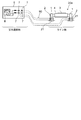
- FIG. 3 is a schematic diagram showing the connection between the manual measurement terminal box 5 and the insulating conveyance section 20a.
- the manual measurement terminal box 5 includes a tester 6 and a plurality of measurement terminals 7.
- the tester 6 may not be permanently installed in the manual measurement terminal box 5 but may be brought to the manual measurement terminal box 5 by the measurer during measurement.
- the manual measurement terminal box 5 is installed in, for example, a safety passage or the vicinity thereof, which is a place away from the transfer area.
- the wiring 90 is connected to the insulation conveyance part 20a so that the insulation board 2 pinched
- the wiring 90 is laid to the manual measurement terminal box 5 and connected to the measurement terminal 7.
- a plurality of measurement terminals 7 are provided corresponding to locations (a plurality of insulating plate installation portions) for insulation measurement.
- a plurality of measurement terminals 7 electrically connected to the plurality of insulated transfer units 20a are collected in a manual measurement terminal box 5 installed at a location away from the transfer area.
- the measurer can perform insulation measurement using the tester 6 without leaving the manual measurement terminal box 5. The measurer can safely measure insulation even when the rolled material 3 is being conveyed.
- the manual measurement terminal box 5 includes a first voltage dividing circuit including a measurement power supply (battery inside the tester 6), a resistance for dividing the power supply voltage (resistance inside the tester 6), and an insulation resistance of the insulating conveyance unit 20a. It is composed.
- FIG. 4 is a circuit diagram showing the concept of the automatic measurement circuit 50.
- the automatic measurement circuit 50 follows a general analog tester circuit. This is because it is common to use a tester for manual measurement, and it is preferable for the measurer to manage and evaluate measured values from the same perspective, whether manual or automatic. It is.
- Measurement is performed with a voltage dividing circuit that uses a dry cell inside the tester to pass a current through the magnification resistance inside the tester. A voltage corresponding to the current flowing through the magnification resistor inside the tester appears. A current corresponding to this voltage and the resistance inside the tester is generated to move the meter. The number of ⁇ is assigned to the scale according to this current.
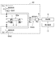
- FIG. 5 is a schematic diagram of the insulation monitoring apparatus excluding the manual measurement terminal box 5 from FIG.
- the automatic measurement circuit 50 constitutes a second voltage dividing circuit including a measurement power supply (DC power supply), a resistance R1 that divides the power supply voltage VDC , an insulation resistance R2 of the insulating conveyance unit 20a, and an analog input unit 8. is doing.
- the insulation monitoring device further includes a control unit 9 and a display device 11.
- the resistance value R3 of the analog input unit 8 is generally very high and can be ignored in the calculation formula.
- the controller 9 calculates the resistance value Rn from the voltage Vn input to the analog input unit 8 in the automatic measuring circuit 50 and the above-described calculation formula Vn / (V DC -Vn) ⁇ R1.
- the control unit 9 can output (screen display) the calculated value to the display device 11 as an insulation resistance value for evaluating the insulation state of the insulation transport unit 20a.
- control unit 9 can compare the insulation resistance value obtained from the automatic measurement circuit 50 with the management value and output the comparison result to the display device 11.
- FIG. 9 is a graph showing an example of data processing of insulation monitoring measurement data by the control unit 9.
- FIG. 9 shows the time variation of the insulation resistance value.
- the control value threshold value
- the table roll 4 of the insulating conveyance unit 20a disposed before and after the induction heating device 10 in the rolling line is internally water-cooled. This is to prevent the outside water for cooling the table roll from being applied to the induction heating device 10 in order to keep the insulation of the induction heating device 10 which is an electrical product. For this reason, the internal water-cooled table roll 4 disposed before and after the induction heating device 10 cannot obtain an insulation resistance value of a megohm level required for a general electric product, and is a few kilohm level. Therefore, the management value of the insulation resistance can be set, for example, from 1 k ⁇ to 2 k ⁇ .
- an induction current indicated by a broken line in FIG. 6B flows through the rolled material 3 to the ground.
- the induction current due to the operation of the induction heating device 10 or the rolling material 3 riding on the table roll 4 to be measured is a disturbance that lowers the measurement accuracy.
- a measurement person avoids measurement disturbance by performing a measurement by visually checking that the induction heating apparatus 10 is stopped and the rolled material 3 is not on the table roll 4 to be measured. Can do.
- the state where the induction heating device 10 is stopped and the rolled material 3 is not on the table roll 4 to be measured can be provided as logic and reflected in the measurement command.
- control unit 9 receives the detection of the off state of the induction heating device 10 and the state in which the rolled material 3 is not on the table roll 4 to be measured, and the insulating conveyance unit to be measured by the automatic measurement circuit 50. Measurement of the insulation resistance of 20a is performed.
- rolling material detection sensors 13 a and 13 b and a measuring roll (pulse counter) 14 are installed in the rolling line in order to perform conveyance control of the rolled material 3.
- the measuring roll 14 calculates the conveyance speed of the rolled material 3.
- the rolling material detection sensors 13a and 13b are, for example, MD (Hot Metal Detector) or a thermometer.
- FIG. 7 illustrates five insulated table rolls (insulation rolls) 4. Then, No. 1, No. 2, No. 3, No. 4, No. 5 are given to the five insulating rolls 4 in order from the upstream side in the conveying direction of the rolled material 3.
- An entrance-side rolled material detection sensor 13a is installed in the vicinity of the most upstream insulating roll 4 to which No. 1 is attached.
- An exit-side rolled material detection sensor 13b is installed in the vicinity of the most downstream insulating roll 4 to which No. 5 is attached.
- the control unit 9 detects that the rolled material 3 is not on the insulating roll 4 to be measured, and that the induction heating device 10 is not in operation, and performs measurement. Outputs a command.
- the connection points (switches) SW1, SW2, and SW3 shown in FIG. 5 are turned on, and automatic resistance measurement of the insulation transfer unit 20a to be measured is performed.
- FIGS. 8A and 8B are tables showing conditions for executing insulation monitoring measurement (conditions for outputting measurement commands).
- FIG. 8A shows common conditions for the five insulating rolls 4.
- FIG. 8B shows a case where conditioning is performed for each insulating roll 4.
- the rolled material 3 Since there are many cases where a plurality of rolled materials (coarse bars) 3 are transported one after another without putting a gap on the characteristics of the rolling operation, the rolled material 3 is not on any of the insulating rolls 4. It may be difficult.
- the measurement timing can be sequentially set from the upstream insulating roll 4 through which the rolled material 3 has already passed.
- the tail end of the rolled material 3 has passed the insulating roll 4 of No. 1 by the off detection of the detection sensor 13a on the entry side, the on detection of the detection sensor 13b on the exit side, and the distance calculation by the measuring roll 14. Can be detected.
- the controller 9 turns on the measurement command for the No. 1 insulating roll 4.
- the insulation measurement of the insulating roll 4 can be performed even during the rolling operation without stopping the rolling operation.
- the insulation monitoring device and the monitoring method according to the embodiment described above it is possible to grasp the decreasing tendency of the insulation resistance of the table roll 4 in time series with a very simple device configuration. This can be utilized for an efficient plan of periodic inspection around the table roll 4, frequency of cleaning, and work amount. Moreover, it can be expected to predict in advance the possibility of arc spots.
- the present invention is not limited to a hot rolling line in which an edge heater is installed, but can also be applied to a plant or facility having an element whose insulation resistance is to be measured and monitored.
Landscapes
- Engineering & Computer Science (AREA)
- Mechanical Engineering (AREA)
- Physics & Mathematics (AREA)
- General Physics & Mathematics (AREA)
- Electromagnetism (AREA)
- Control Of Conveyors (AREA)
- General Induction Heating (AREA)
Abstract
圧延材搬送部の絶縁監視装置は、圧延材を加熱する誘導加熱装置の前後に配置された絶縁搬送部の絶縁抵抗を、測定用電源電圧を分割する抵抗のひとつとして含む第1分圧回路を構成する手動測定用端子箱と、前記絶縁抵抗を、測定用電源電圧を分割する抵抗のひとつとして含む第2分圧回路を構成する自動測定回路と、を備えている。絶縁搬送部の絶縁状態を安全に且つ精度良く監視する。
Description
本発明は、圧延材搬送部の絶縁監視装置に関する。
一般に熱間圧延ラインでは、圧延材を加熱炉で圧延可能な温度にまで加熱し、粗圧延機にて粗圧延して粗バーと呼ばれる状態に成形する。さらに、粗バーを仕上げ圧延機にかけることで所望の板厚に成形した製品を得ている。
このような熱間圧延ラインにおいては、粗バーが仕上げ圧延機に到達するまでに温度低下が起こる。そこで、粗バーの昇温や均熱を目的として誘導加熱装置が設置されている。例えば、粗バーの幅方向の両端部は特に温度が低下しやすいので、その両端部を昇温させるエッジヒータが設置されている。
例えば誘導加熱装置がエッジヒータとして粗バーの両端部に配置されている。その誘導加熱装置の加熱コイルから発生する磁束を粗バーに鎖交させることにより粗バーに渦電流が発生し、この渦電流によるジュール熱にて粗バーを加熱する。
このとき、粗バーに発生した渦電流が軸電流となって粗バーからテーブルロールを伝って大地に流れる。粗バーとテーブルロールが安定して接触している場合には特に問題にはならないが、粗バーの搬送中の上下振動や粗バー自身の曲がりにより、粗バーとテーブルロールとの接触が不安定になることがある。その場合、粗バーがテーブルロールから離れた瞬間に放電を起して粗バーやテーブルロールに放電疵をつける問題が起こり得る。このような問題に対して、例えば特許文献1が提案されている。
テーブルロールが絶縁されている状態であれば軸電流の発生は抑えられる。そのため、日常的または定期的にテーブルロールの絶縁状態を監視することが有効である。
粗バーからのスケールやデスケーリング水の落下、圧延ラインの湿熱環境により、常にテーブルロールの絶縁を維持することは難しい。定期的にスケールや塵埃などの除去が必要であるが、日常的または定期的にテーブルロールの絶縁状態を確認すれば絶縁低下の傾向を把握することができ、また、メンテナンス対象のテーブルロールを明らかにすることもできる。以下に説明する実施形態によれば、このようなテーブルロール(絶縁搬送部)の絶縁状態を安全に且つ精度良く監視する絶縁監視装置を提供するものである。
本発明の一態様によれば、圧延材を加熱する誘導加熱装置の前後に配置された絶縁搬送部の絶縁抵抗を、測定用電源電圧を分割する抵抗のひとつとして含む第1分圧回路を構成する手動測定用端子箱と、前記絶縁抵抗を、測定用電源電圧を分割する抵抗のひとつとして含む第2分圧回路を構成する自動測定回路と、を備えた圧延材搬送部の絶縁監視装置が提供される。
絶縁搬送部まわりの点検清掃の頻度および作業量を効率よく計画することが可能となる。
図1は、実施形態の絶縁監視装置の構成を示す模式図である。
実施形態の絶縁監視装置は、手動測定用端子箱5と自動測定回路50を備えている。後述するように、手動測定用端子箱5は第1分圧回路を構成し、自動測定回路50は第2分圧回路を構成する。
図7は、実施形態の圧延材搬送ラインの模式図である。
図7は、例えば、熱間圧延ラインにおける粗圧延機と仕上げ圧延機との間の搬送ラインを示す。粗圧延後の圧延材(粗バー)3が、複数の搬送部20a、20b上を図7において右から左に搬送されていく。
その搬送ラインに誘導加熱装置10が配置されている。図7では、例えば2つの誘導加熱装置10を示す。誘導加熱装置10は、圧延材(粗バー)3の幅方向(紙面奥行き方向)の両端部を加熱する。
複数の搬送部20a、20bは、誘導加熱装置10の前後(搬送方向の上流側および下流側)に配置された複数の絶縁搬送部20aを含む。図7では、例えば5個の絶縁搬送部20aが誘導加熱装置10の前後に配置されている。
図2は、絶縁搬送部20aの模式図である。
絶縁搬送部20aは、テーブルロール4と、テーブルロール4を回転可能に支持する軸受1と、軸受1を大地上に支持する支持部21とを有する。複数のテーブルロール4が、圧延材3の搬送方向に互いに離間して並んでいる。
テーブルロール4、軸受1、および支持部21は、圧延材3の搬送に十分な強度をもつ金属製である。支持部21には絶縁板2が挟まれている。絶縁板2は、大地とテーブルロール4との間を絶縁する。
1本のテーブルロール4の両端のそれぞれが軸受1および支持部21を介して大地上に支持されている。その両端の支持部21のそれぞれに絶縁板2が挟まれている。誘導加熱装置10の前後エリア以外のエリアは軸電流発生のおそれがなく、そのエリアには、図7に示すように絶縁板2を持たない搬送部20bが配置されている。
図3は、手動測定用端子箱5と絶縁搬送部20aとの接続を示す模式図である。
手動測定用端子箱5は、テスター6と、複数の測定用端子7を備えている。または、テスター6は、手動測定用端子箱5に常設せずに、測定者が測定のときに手動測定用端子箱5に持ってきてもよい。
圧延材3の搬送エリアは危険であるので安全通路が設けられている。手動測定用端子箱5は、その搬送エリアから離れた場所である例えば安全通路またはその近辺に設置されている。
軸受1の支持部21に挟まれた絶縁板2を跨ぐように絶縁搬送部20aに配線90を接続する。その配線90を手動測定用端子箱5まで敷設し、測定用端子7に接続する。絶縁測定する箇所(複数の絶縁板設置部)に対応して複数の測定用端子7が設けられている。複数の絶縁搬送部20aと電気的に接続された複数の測定用端子7が、搬送エリアから離れた場所に設置された手動測定用端子箱5に集約されている。測定者はテスター6を使って手動測定端子箱5から離れることなく絶縁測定することができる。測定者は圧延材3が搬送されているときでも安全に絶縁測定を行うことができる。
手動測定用端子箱5は、測定用電源(テスター6内部の電池)と、その電源電圧を分割する抵抗(テスター6内部の抵抗)および絶縁搬送部20aの絶縁抵抗を含む第1分圧回路を構成している。
図4は、自動測定回路50の概念を示す回路図である。
自動測定回路50は、一般的なアナログテスターの回路を踏襲している。これは、手動測定する場合にはテスターを用いることが一般的であることから、測定者は手動測定でも自動測定でも同じ目線(perspective)で測定値を管理および評価できるようにすることが好ましいからである。
ここでテスターでの抵抗測定について簡単に述べる。テスター内部の乾電池を使ってテスター内部の倍率抵抗を通して測定物に電流を流す分圧回路で測定が行われる。テスター内部の倍率抵抗に流れた電流に応じた電圧が現れる。この電圧とテスター内部の抵抗に見合った電流が発生してメーターが動く。この電流に応じてΩ数を目盛りに割り振る。
図5は、図1から手動測定用端子箱5を除いた絶縁監視装置の模式図である。
自動測定回路50は、測定用電源(直流電源)と、その電源電圧VDCを分割する抵抗R1および絶縁搬送部20aの絶縁抵抗R2と、アナログ入力ユニット8とを含む第2分圧回路を構成している。絶縁監視装置は、さらに制御部9と表示装置11を備えている。
ここで、第2分圧回路におけるアナログ入力ユニット8に接続される端子に流れる電流をI1、その端子の電圧をVn、その端子の抵抗値をRn、アナログ入力ユニット8の内部抵抗をR3とすると以下の式が成り立つ。但し、アナログ入力ユニット8の抵抗値R3は一般的に非常に高いため計算式では無視しても余り差支えない。
I1=VDC/(R1+Rn)
Rn=R2×R3/(R2+R3) … 計算の便宜上合成抵抗とする
I1=Vn/Rn
Vn/Rn=VDC/(R1+Rn)
Vn×(R1+Rn)=VDC×Rn
Rn=Vn/(VDC-Vn)×R1 … アナログ入力ユニット8の内部抵抗込みの絶縁抵抗値
R2=1/(1/Rn-1/R3) … アナログ入力ユニット8の内部抵抗無しの絶縁抵抗値
Rn=R2×R3/(R2+R3) … 計算の便宜上合成抵抗とする
I1=Vn/Rn
Vn/Rn=VDC/(R1+Rn)
Vn×(R1+Rn)=VDC×Rn
Rn=Vn/(VDC-Vn)×R1 … アナログ入力ユニット8の内部抵抗込みの絶縁抵抗値
R2=1/(1/Rn-1/R3) … アナログ入力ユニット8の内部抵抗無しの絶縁抵抗値
自動測定回路50内のアナログ入力ユニット8に入力した電圧Vnと前述の計算式 Vn/(VDC-Vn)×R1により、制御部9は抵抗値Rnを算出する。制御部9は、その算出値を絶縁搬送部20aの絶縁状態を評価する絶縁抵抗値として表示装置11に出力(画面表示)することができる。
また、制御部9は、自動測定回路50から得られた絶縁抵抗値を管理値と比較し、その比較結果を表示装置11に出力することができる。
図9は、その制御部9による絶縁監視測定データのデータ処理例を示すグラフである。
図9は、絶縁抵抗値の時間変化を示す。そして、絶縁抵抗値が管理値(しきい値)よりも下回った場合には表示装置11にアラームを出力させることもできる。
圧延ラインにおいて誘導加熱装置10の前後に配置する絶縁搬送部20aのテーブルロール4は内部水冷にすることが一般的である。電気品である誘導加熱装置10の絶縁を保つためにテーブルロール冷却用外水を誘導加熱装置10にかからないようにするためである。そのため、誘導加熱装置10の前後に配置された内部水冷されたテーブルロール4では一般的な電気品に求められるメグオームレベルの絶縁抵抗値は得られず、数キロオームレベルである。したがって、上記絶縁抵抗の管理値として、例えば1kΩ以上2kΩ以下を設定することができる。
ここで、図6(a)に示すように、圧延材3が測定対象のテーブルロール4と、その他のテーブルロール4に乗っている状態になると、それらの複数のテーブルロール4間に破線で示すような電気回路(廻り回路)が形成されてしまう。これは、絶縁抵抗の測定精度を低下させる要因となる。
また、誘導加熱装置10がオンになると、図6(b)において破線で示す誘導電流が、圧延材3を介して大地に流れてしまう。
すなわち、絶縁搬送部20aの絶縁抵抗測定時に、誘導加熱装置10の運転による誘導電流や、測定対象のテーブルロール4に圧延材3が乗ってしまうことは、測定精度を低下させる外乱となってしまう。
手動測定の場合は測定者が誘導加熱装置10の停止、および圧延材3が測定対象のテーブルロール4に乗っていない状態を目視で確認して測定を実行することで、測定外乱を回避することができる。
一方、自動測定回路50を使った測定では、誘導加熱装置10の停止、および圧延材3が測定対象のテーブルロール4に乗っていない状態をロジックとして設けて、測定指令に反映させることができる。
すなわち、制御部9は、誘導加熱装置10のオフ状態、且つ測定対象のテーブルロール4の上に圧延材3が乗っていない状態の検出を受けて、自動測定回路50による測定対象の絶縁搬送部20aの絶縁抵抗の測定を実行する。
図7に示すように、圧延ラインでは圧延材3の搬送制御を行うために、圧延材検出センサ13a、13bと、メジャーリングロール(パルスカウンター)14が設置されている。メジャーリングロール14は、圧延材3の搬送速度を計算する。圧延材検出センサ13a、13bは、例えばMD(Hot Metal Detector)または温度計である。
図7では、絶縁されたテーブルロール(絶縁ロール)4を5本例示している。そして、5本の絶縁ロール4に、圧延材3の搬送方向の上流側から順にNo.1、No.2、No.3、No.4、No.5を付している。
No.1が付された最も上流側の絶縁ロール4の近傍には、入側の圧延材検出センサ13aが設置されている。No.5が付された最も下流側の絶縁ロール4の近傍には出側の圧延材検出センサ13bが設置されている。5本の絶縁ロール4のいずれの上にも圧延材3が乗っていないとき、入側の検出センサ13aおよび出側の検出センサ13bの両方共がオフになる。
自動測定回路50を利用した監視装置によれば、制御部9が、測定したい絶縁ロール4に圧延材3が乗っていないこと、および誘導加熱装置10が運転していないことを検出して、測定指令を出力する。その測定指令の出力により、図5に示す接続点(スイッチ)SW1、SW2、SW3がオンになり、測定対象の絶縁搬送部20aの自動抵抗測定が実行される。
図8(a)及び(b)は、絶縁監視測定実行の条件(測定指令を出力する条件)を示す表である。
図8(a)は、5本の絶縁ロール4に対する共通条件を表す。
すなわち、誘導加熱装置10がオフで、入側の検出センサ13aがオフで、且つ出側の検出センサ13bがオフのとき、5本の絶縁ロール4のうちのいずれの絶縁ロール4についても測定指令を出力できる。
図8(b)は、絶縁ロール4ごとに条件付けする場合を示す。
圧延操業の特性上、複数の圧延材(粗バー)3が間髪を入れずに次々と搬送される場合も多いので、すべての絶縁ロール4のいずれにも圧延材3が乗っていない状態にはなりにくい場合がある。
その場合は、検出センサ13a、13bおよびメジャーリングロール14から得られる圧延材3のトラッキング情報を利用して、圧延材3が今、No.1からNo.5の絶縁ロール4のどこまで進んだのかを検出して、例えば圧延材3がすでに通り抜けた上流側の絶縁ロール4から順次測定タイミングを設定することができる。
例えば、入側の検出センサ13aのオフ検出、出側の検出センサ13bのオン検出、およびメジャーリングロール14による距離計算により、圧延材3の尾端がNo.1の絶縁ロール4を通り過ぎたことを検出することができる。これを検出すると、制御部9はNo.1の絶縁ロール4に対する測定指令をオンにする。
この方法によれば、圧延操業を停止することなく、圧延操業中であっても絶縁ロール4の絶縁測定を行える。
以上説明した実施形態による絶縁監視装置および監視方法によれば、非常に簡素な装置構成で、テーブルロール4の絶縁抵抗の低下傾向を時系列に掴む事ができる。これは、テーブルロール4廻りの定期点検、清掃の頻度、作業量の効率的な計画に生かすことができる。また、アークスポットが発生する可能性を予め予測する事が期待できる。
この発明は、エッジヒータを設置した熱間圧延ラインに限定することなく、絶縁抵抗を測定及び監視したい要素をもつプラントや設備に対しても適用することができる。
本発明のいくつかの実施形態を説明したが、これらの実施形態は、例として提示したものであり、発明の範囲を限定することは意図していない。これら新規な実施形態は、その他の様々な形態で実施されることが可能であり、発明の要旨を逸脱しない範囲で、種々の省略、置き換え、変更を行うことができる。これら実施形態やその変形は、発明の範囲や要旨に含まれるとともに、請求の範囲に記載された発明とその均等の範囲に含まれる。
Claims (4)
- 圧延材を加熱する誘導加熱装置の前後に配置された絶縁搬送部の絶縁抵抗を、測定用電源電圧を分割する抵抗のひとつとして含む第1分圧回路を構成する手動測定用端子箱と、
前記絶縁抵抗を、測定用電源電圧を分割する抵抗のひとつとして含む第2分圧回路を構成する自動測定回路と、
を備えた圧延材搬送部の絶縁監視装置。 - 前記自動測定回路から得られた絶縁抵抗値を管理値と比較し、その比較結果を表示装置に出力する制御部をさらに備えた請求項1記載の圧延材搬送部の絶縁監視装置。
- 前記誘導加熱装置のオフ状態、且つ測定対象の絶縁搬送部の上に前記圧延材が乗っていない状態の検出を受けて、前記自動測定回路による前記測定対象の絶縁搬送部の絶縁抵抗の測定を実行する制御部をさらに備えた請求項1記載の圧延材搬送部の絶縁監視装置。
- 前記圧延材の搬送エリアから離れた場所に設置された前記手動測定用端子箱に、複数の絶縁搬送部と接続された複数の測定用端子が集約されている請求項1記載の圧延材搬送部の絶縁監視装置。
Priority Applications (2)
| Application Number | Priority Date | Filing Date | Title |
|---|---|---|---|
| PCT/JP2017/001923 WO2018134965A1 (ja) | 2017-01-20 | 2017-01-20 | 圧延材搬送部の絶縁監視装置 |
| TW106107964A TWI624670B (zh) | 2017-01-20 | 2017-03-10 | 軋延材搬送部之絕緣監視裝置 |
Applications Claiming Priority (1)
| Application Number | Priority Date | Filing Date | Title |
|---|---|---|---|
| PCT/JP2017/001923 WO2018134965A1 (ja) | 2017-01-20 | 2017-01-20 | 圧延材搬送部の絶縁監視装置 |
Publications (1)
| Publication Number | Publication Date |
|---|---|
| WO2018134965A1 true WO2018134965A1 (ja) | 2018-07-26 |
Family
ID=62909108
Family Applications (1)
| Application Number | Title | Priority Date | Filing Date |
|---|---|---|---|
| PCT/JP2017/001923 Ceased WO2018134965A1 (ja) | 2017-01-20 | 2017-01-20 | 圧延材搬送部の絶縁監視装置 |
Country Status (2)
| Country | Link |
|---|---|
| TW (1) | TWI624670B (ja) |
| WO (1) | WO2018134965A1 (ja) |
Citations (3)
| Publication number | Priority date | Publication date | Assignee | Title |
|---|---|---|---|---|
| JPS4846670U (ja) * | 1971-10-01 | 1973-06-19 | ||
| JPH05281272A (ja) * | 1992-03-30 | 1993-10-29 | Sakai Tekkosho:Kk | 絶縁抵抗自動測定装置 |
| JP2003048010A (ja) * | 2001-08-02 | 2003-02-18 | Nkk Corp | 圧延用搬送ローラ絶縁抵抗監視方法及びシステム並びに圧延材の製造方法 |
Family Cites Families (4)
| Publication number | Priority date | Publication date | Assignee | Title |
|---|---|---|---|---|
| DE19640058C2 (de) * | 1996-09-30 | 1999-06-10 | Heraeus Sensor Nite Gmbh | Leiterplatte mit Zugentlastung für Anschluß-Kabel, Verfahren zu deren Herstellung und Verbindung sowie deren Verwendung |
| JP4739792B2 (ja) * | 2005-03-31 | 2011-08-03 | 東芝三菱電機産業システム株式会社 | 誘導加熱装置及び誘導加熱装置のアークスポット抑制方法 |
| US8289031B1 (en) * | 2011-05-16 | 2012-10-16 | Rao Dantam K | Apparatus for measuring insulation characteristics of coated steel sheet |
| WO2015121974A1 (ja) * | 2014-02-14 | 2015-08-20 | 東芝三菱電機産業システム株式会社 | 圧延機の電動機速度制御装置 |
-
2017
- 2017-01-20 WO PCT/JP2017/001923 patent/WO2018134965A1/ja not_active Ceased
- 2017-03-10 TW TW106107964A patent/TWI624670B/zh not_active IP Right Cessation
Patent Citations (3)
| Publication number | Priority date | Publication date | Assignee | Title |
|---|---|---|---|---|
| JPS4846670U (ja) * | 1971-10-01 | 1973-06-19 | ||
| JPH05281272A (ja) * | 1992-03-30 | 1993-10-29 | Sakai Tekkosho:Kk | 絶縁抵抗自動測定装置 |
| JP2003048010A (ja) * | 2001-08-02 | 2003-02-18 | Nkk Corp | 圧延用搬送ローラ絶縁抵抗監視方法及びシステム並びに圧延材の製造方法 |
Also Published As
| Publication number | Publication date |
|---|---|
| TWI624670B (zh) | 2018-05-21 |
| TW201827840A (zh) | 2018-08-01 |
Similar Documents
| Publication | Publication Date | Title |
|---|---|---|
| JP5973716B2 (ja) | 変圧器健全性を監視する方法およびシステム | |
| CN107107137B (zh) | 轧制生产线的蛇行控制装置 | |
| KR102268968B1 (ko) | 유도 발열 롤러 장치, 및 유도 코일의 온도 검출 기구 | |
| TWI665942B (zh) | 感應發熱輥裝置 | |
| JP2012148310A (ja) | 鋼板エッジ部の加熱方法 | |
| TWI682691B (zh) | 感應發熱輥裝置 | |
| US10095199B2 (en) | Energy consumption predicting device for rolling line | |
| JP6164181B2 (ja) | 誘導加熱装置および誘導加熱方法 | |
| JP5012997B2 (ja) | 誘導加熱装置の劣化診断装置 | |
| WO2018134965A1 (ja) | 圧延材搬送部の絶縁監視装置 | |
| JP5727807B2 (ja) | 光ファイバ温度センサ | |
| JP4786375B2 (ja) | 熱間圧延装置及び方法 | |
| JP2007060787A (ja) | 電源トランス保護システム | |
| TWI655815B (zh) | 具有封閉迴路回饋與交錯取樣之主動游離控制 | |
| RU2559785C1 (ru) | Способ контроля ресурса изоляции силового трансформатора | |
| JP4377845B2 (ja) | ジャケットロールのコイル焼損防止方法 | |
| JP7151636B2 (ja) | データ収集装置 | |
| JP4649795B2 (ja) | 圧延用搬送ローラ絶縁抵抗監視方法及びシステム並びに圧延材の製造方法 | |
| JPWO2009013827A1 (ja) | 鋼板の製造方法及びその方法を用いた製造装置 | |
| JP2763038B2 (ja) | 炉温異常分布警報装置 | |
| JP6350820B2 (ja) | 放電処理装置 | |
| JP2017102326A (ja) | 定着装置、及び温度センサーの異常検知方法 | |
| JP6076951B2 (ja) | ヒータの配線用の電線に特徴を有する射出成形機 | |
| JP5310459B2 (ja) | 鋼板の加熱制御方法 | |
| JP7754337B1 (ja) | 鉄鋼プラントのメンテナンス支援システム |
Legal Events
| Date | Code | Title | Description |
|---|---|---|---|
| 121 | Ep: the epo has been informed by wipo that ep was designated in this application |
Ref document number: 17892765 Country of ref document: EP Kind code of ref document: A1 |
|
| NENP | Non-entry into the national phase |
Ref country code: DE |
|
| 122 | Ep: pct application non-entry in european phase |
Ref document number: 17892765 Country of ref document: EP Kind code of ref document: A1 |
|
| NENP | Non-entry into the national phase |
Ref country code: JP |