WO2018131664A1 - センサ送信機、車輪位置検出装置およびそれを備えたタイヤ空気圧検出装置 - Google Patents
センサ送信機、車輪位置検出装置およびそれを備えたタイヤ空気圧検出装置 Download PDFInfo
- Publication number
- WO2018131664A1 WO2018131664A1 PCT/JP2018/000533 JP2018000533W WO2018131664A1 WO 2018131664 A1 WO2018131664 A1 WO 2018131664A1 JP 2018000533 W JP2018000533 W JP 2018000533W WO 2018131664 A1 WO2018131664 A1 WO 2018131664A1
- Authority
- WO
- WIPO (PCT)
- Prior art keywords
- acceleration
- sensor
- wheel
- attached
- value
- Prior art date
Links
Images


Classifications
-
- B—PERFORMING OPERATIONS; TRANSPORTING
- B60—VEHICLES IN GENERAL
- B60C—VEHICLE TYRES; TYRE INFLATION; TYRE CHANGING; CONNECTING VALVES TO INFLATABLE ELASTIC BODIES IN GENERAL; DEVICES OR ARRANGEMENTS RELATED TO TYRES
- B60C23/00—Devices for measuring, signalling, controlling, or distributing tyre pressure or temperature, specially adapted for mounting on vehicles; Arrangement of tyre inflating devices on vehicles, e.g. of pumps or of tanks; Tyre cooling arrangements
- B60C23/02—Signalling devices actuated by tyre pressure
- B60C23/04—Signalling devices actuated by tyre pressure mounted on the wheel or tyre
- B60C23/0486—Signalling devices actuated by tyre pressure mounted on the wheel or tyre comprising additional sensors in the wheel or tyre mounted monitoring device, e.g. movement sensors, microphones or earth magnetic field sensors
- B60C23/0488—Movement sensor, e.g. for sensing angular speed, acceleration or centripetal force
-
- B—PERFORMING OPERATIONS; TRANSPORTING
- B60—VEHICLES IN GENERAL
- B60C—VEHICLE TYRES; TYRE INFLATION; TYRE CHANGING; CONNECTING VALVES TO INFLATABLE ELASTIC BODIES IN GENERAL; DEVICES OR ARRANGEMENTS RELATED TO TYRES
- B60C23/00—Devices for measuring, signalling, controlling, or distributing tyre pressure or temperature, specially adapted for mounting on vehicles; Arrangement of tyre inflating devices on vehicles, e.g. of pumps or of tanks; Tyre cooling arrangements
- B60C23/02—Signalling devices actuated by tyre pressure
- B60C23/04—Signalling devices actuated by tyre pressure mounted on the wheel or tyre
- B60C23/0408—Signalling devices actuated by tyre pressure mounted on the wheel or tyre transmitting the signals by non-mechanical means from the wheel or tyre to a vehicle body mounted receiver
- B60C23/0415—Automatically identifying wheel mounted units, e.g. after replacement or exchange of wheels
- B60C23/0416—Automatically identifying wheel mounted units, e.g. after replacement or exchange of wheels allocating a corresponding wheel position on vehicle, e.g. front/left or rear/right
-
- B—PERFORMING OPERATIONS; TRANSPORTING
- B60—VEHICLES IN GENERAL
- B60C—VEHICLE TYRES; TYRE INFLATION; TYRE CHANGING; CONNECTING VALVES TO INFLATABLE ELASTIC BODIES IN GENERAL; DEVICES OR ARRANGEMENTS RELATED TO TYRES
- B60C23/00—Devices for measuring, signalling, controlling, or distributing tyre pressure or temperature, specially adapted for mounting on vehicles; Arrangement of tyre inflating devices on vehicles, e.g. of pumps or of tanks; Tyre cooling arrangements
- B60C23/02—Signalling devices actuated by tyre pressure
- B60C23/04—Signalling devices actuated by tyre pressure mounted on the wheel or tyre
- B60C23/0486—Signalling devices actuated by tyre pressure mounted on the wheel or tyre comprising additional sensors in the wheel or tyre mounted monitoring device, e.g. movement sensors, microphones or earth magnetic field sensors
- B60C23/0489—Signalling devices actuated by tyre pressure mounted on the wheel or tyre comprising additional sensors in the wheel or tyre mounted monitoring device, e.g. movement sensors, microphones or earth magnetic field sensors for detecting the actual angular position of the monitoring device while the wheel is turning
-
- G—PHYSICS
- G01—MEASURING; TESTING
- G01L—MEASURING FORCE, STRESS, TORQUE, WORK, MECHANICAL POWER, MECHANICAL EFFICIENCY, OR FLUID PRESSURE
- G01L17/00—Devices or apparatus for measuring tyre pressure or the pressure in other inflated bodies
Definitions
- the present disclosure relates to a sensor transmitter and a wheel position detection device that detect where a wheel is attached to a vehicle, and is particularly suitable for application to a tire pressure detection device that detects tire pressure.
- TPMS Tire Pressure Monitoring System
- a sensor transmitter equipped with a sensor such as a pressure sensor is directly attached to a wheel side to which a tire is attached.
- an antenna and a receiver are provided on the vehicle body side.
- wheel position detection for detecting the wheel to which the sensor transmitter is attached is performed by various methods as shown in the following (1) to (6).
- the sensor transmitter has a trigger signal reception function, and the wheel position is detected by performing bidirectional communication in which data indicating the reception intensity when the trigger signal is received is transmitted to the receiver side. Yes. Specifically, when trigger devices are arranged at different distances from each sensor transmitter and a trigger signal is output from the trigger device, the trigger signal is measured at different reception intensities at each sensor transmitter. Yes. The wheel position is detected based on the difference in reception intensity.
- a sensor transmitter includes a biaxial acceleration sensor (hereinafter referred to as a G sensor) that can detect acceleration in the rotational direction and radial direction of a wheel (see, for example, Patent Document 1). Since the phase difference of the detection signal of the G sensor for each axis changes depending on the rotation direction of the wheel, the receiver determines whether the transmitter is attached to the left or right wheel by comparing the phase difference. The wheel position is detected.
- a G sensor biaxial acceleration sensor
- a wheel position detection method in which the steered wheel has a longer moving distance than the driven wheel, and identifies which sensor transmitter is installed on the front or rear wheel. Since the centrifugal force of the rotating tire is proportional to the wheel speed, a value proportional to the moving distance of the tire is generated by integrating the centrifugal force of the wheel detected by the G sensor. The receiver receives this value, and determines that the longer traveling distance of the tire is the steering wheel and the shorter one is the driven wheel.
- ABS anti-lock brake
- the method (1) requires additional equipment such as a trigger machine, the apparatus configuration is complicated and the cost is increased.
- the method (2) there are restrictions on the mounting position of the receiver or the receiving antenna, and the mounting position is further limited when considering vehicle adaptation.
- a special sensor called a biaxial G sensor is required.
- the method (4) when the tire diameter is different between the front and rear wheels, it is difficult to discriminate between the steered wheel and the driven wheel, resulting in erroneous determination.
- the method (5) since the information of the wheel speed sensor used for the ABS control is used, the communication specification with the wheel position detection device or the tire pressure detection device becomes complicated.
- the method (6) since it is difficult to obtain the detection accuracy of the tire pressure, the wheel position cannot be accurately detected.
- An object of the present invention is to provide a sensor transmitter, a wheel position detection device, and a tire pressure detection device using the sensor transmitter.
- a calculation quadratic function that approximates the median of the calculated acceleration value by a quadratic function when the acceleration sensor is attached to the wheel at an inclination angle, and a calculation of acceleration A calculated linear function that approximates the median of the differential value of the value by a linear function, an actual measurement quadratic function that approximates the median of the amplitude of the value actually detected by the acceleration sensor by a quadratic function, and an acceleration sensor Based on the measured linear function that approximates the median of the differential value of the actually detected value with a linear function, the sensor transmitter itself provided with the first control unit is attached to the right wheel. Which of the left wheels A constant.
- the coefficient of the quadratic term in the measured quadratic function is C1
- the first order term is C2
- the constant term is C3.
- C1 and C2 are calculated
- C3 is calculated based on the calculated C1 and C2, the median value at one point in the measured quadratic function, and the time when the median value is reached.
- the acceleration of the vehicle body is a
- the initial speed of the vehicle speed is v 0
- the inclination angle is ⁇ set
- the acceleration / deceleration instruction value indicating whether the vehicle is accelerating or decelerating is B
- the sensor transmitter itself calculates the tilt angle, and in addition to the tilt angle, based on the calculated quadratic function, the calculated primary function, the measured quadratic function, and the measured primary function, the right wheel and the left wheel It is estimated to which of these is attached.
- additional equipment such as a trigger machine is not required, and the apparatus configuration can be prevented from becoming complicated and costly.
- a special sensor called a biaxial G sensor is not required. Further, it is possible to discriminate between a steered wheel and a driven wheel. And since the information of the wheel speed sensor used for ABS control is not used, the communication specification is not complicated, and it is possible to detect the wheel position with high accuracy without requiring the tire air pressure detection accuracy. .
- FIG. 1 It is a figure showing the whole tire air pressure detection device composition to which the wheel position detection device in a 1st embodiment concerning a 1st embodiment is applied. It is the figure which showed the block configuration of the transmitter. It is the figure which showed the block configuration of the receiver. It is the figure which showed the existing angle (theta) around the axle shaft in the time of the transmitter which incorporates G sensor seen from the right side surface of the vehicle. It is the figure which showed inclination
- FIG. 1 A first embodiment of the present disclosure will be described.
- the tire air pressure detection device shown in FIG. 1 having a function as a wheel position detection device will be described, but the configuration of only the wheel position detection device may be used.
- 1 corresponds to the front-rear direction of the vehicle 1
- the left-right direction of the page corresponds to the left-right direction of the vehicle 1.
- the tire pressure detecting device in the present embodiment will be described.
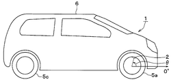
- the tire air pressure detecting device is attached to a vehicle 1 and includes a sensor transmitter 2, a receiver 3, and a display 4.
- the sensor transmitter 2 is attached to each wheel 5a to 5d in the vehicle 1, and in the case of this embodiment, the sensor transmitters 2a to 2d are provided in each of the four wheels 5a to 5d. It has been.
- the sensor transmitters 2a to 2d detect the air pressure of the tires attached to the wheels 5a to 5d, store information on the tire air pressure indicating the detection result in the frame, and transmit the RF.
- the receiver 3 is attached to the vehicle body 6 side of the vehicle 1.
- the receiver 3 RF-receives the frames transmitted from the sensor transmitters 2a to 2d, and performs wheel position detection and tire air pressure detection by performing various processes and calculations based on the detection signals stored therein. Do.
- the configurations of the sensor transmitters 2a to 2d and the receiver 3 will be described with reference to FIGS. 2 (a) and 2 (b).
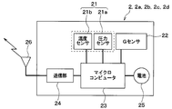
- the sensor transmitter 2 includes a sensing unit 21, a G sensor 22, a microcomputer 23, a transmission unit 24, a battery 25, and a transmission antenna 26. Each unit is driven based on the power supply.
- the sensing unit 21 includes a diaphragm type pressure sensor 21a and a temperature sensor 21b, for example, and outputs a detection signal corresponding to the tire pressure and a detection signal corresponding to the temperature.
- the G sensor 22 detects acceleration in one direction. In the present embodiment, the G sensor 22 detects acceleration in a direction shifted by an arbitrary angle in the circumferential direction with respect to the radial direction of each of the wheels 5a to 5d, that is, the normal direction to the circumferential direction. The mounting angle of the G sensor 22 is adjusted. This will be described later.
- the microcomputer 23 is a well-known computer having a control unit corresponding to the first control unit, and executes predetermined processing including wheel position detection processing and tire air pressure detection processing in accordance with a program stored in a memory in the control unit.
- the memory in the control unit stores individual ID information including identification information unique to the sensor transmitter for identifying each of the sensor transmitters 2a to 2d and identification information unique to the vehicle for identifying the host vehicle. Yes.
- the memory in the control unit stores, for example, the rim diameter of the wheel to which the sensor transmitter 2 is attached as data used for wheel position detection. The rim diameter may be stored in a memory when the sensor transmitter 2 is manufactured, or may be written in an automobile maintenance shop using a communication device when the sensor transmitter 2 is mounted on the wheels 5a to 5d. Of course, when the sensor transmitter 2 and the receiver 3 can perform bidirectional communication, the user can operate the display 4 to obtain the rim diameter data via the receiver 3. You may make it memorize
- the microcomputer 23 receives the detection signal related to the tire air pressure from the sensing unit 21, processes the signal and processes it if necessary, and processes the information related to the tire air pressure in the frame together with the ID information of each of the sensor transmitters 2a to 2d. To store.
- the microcomputer 23 determines that the vehicle is running, for example, when the detected acceleration exceeds a predetermined threshold, and performs acceleration sampling in a short cycle after determining that the vehicle is running.
- the microcomputer 23 detects that the speed of the vehicle 1 (hereinafter referred to as the vehicle speed) is a constant speed based on the detected acceleration, the microcomputer 23 calculates the mounting angle of the G sensor 22.
- the microcomputer 23 estimates which wheel the sensor transmitter 2 itself is mounted on the basis of the actual acceleration detected by the G sensor 22. To do. This estimation is preferably performed during deceleration. That is, during deceleration, a large acceleration change can be obtained in acceleration sampling in a short cycle, which is preferable because wheel position detection can be performed with higher accuracy.
- the microcomputer 23 estimates which of the right wheels 5a and 5c and the left wheels 5b and 5d is attached to its own sensor transmitter 2.
- the microcomputer 23 tires the data indicating the estimation result, the value obtained at the time of estimation, and the like of whether the sensor transmitter 2 is attached to the right wheel 5a, 5c or the left wheel 5b, 5d. It is stored in a frame that stores data related to air pressure. Details of the wheel position estimation performed by the microcomputer 23 will be described later.
- the microcomputer 23 transmits the frame from the transmission antenna 26 to the receiver 3 via the transmission unit 24.
- the process of transmitting this frame toward the receiver 3 is also performed according to the above program. For example, frame transmission is repeatedly performed every predetermined transmission cycle.
- the transmission unit 24 functions as an output unit that transmits a frame transmitted from the microcomputer 23 to the receiver 3 through the transmission antenna 26.
- RF band radio waves are used as radio waves used for transmission.
- the battery 25 supplies power to the microcomputer 23 and the like. In response to the power supply from the battery 25, data relating to tire air pressure in the sensing unit 21, acceleration detection in the G sensor 22, various calculations in the microcomputer 23, and the like are executed.
- the sensor transmitters 2a to 2d configured as described above are attached to, for example, air injection valves in the wheels 5a to 5d, and are arranged so that the sensing unit 21 is exposed inside the tire. That is, the sensor transmitters 2a to 2d are attached at positions away from the rotation centers of the wheels 5a to 5d by a distance corresponding to the rim diameter, specifically, by a distance that is half the rim diameter. As a result, the corresponding tire pressure is detected and a frame is transmitted at a predetermined transmission timing through the transmission antenna 26 provided in each of the sensor transmitters 2a to 2d. Is sent periodically.
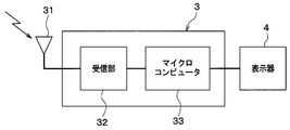
- the receiver 3 is configured to include a receiving antenna 31, a receiving unit 32, and a microcomputer 33.
- the receiving antenna 31 is a single common antenna that collectively receives frames sent from the sensor transmitters 2 and is fixed to the vehicle body 6.
- the receiving unit 32 functions as an input unit that receives a frame transmitted from each sensor transmitter 2 by the receiving antenna 31 and sends it to the microcomputer 33.
- the microcomputer 33 corresponds to a second control unit, and is constituted by a known microcomputer having a CPU, ROM, RAM, I / O, and the like, and performs predetermined processing according to a program stored in the ROM. Execute.
- the microcomputer 33 uses the transmission frames from the sensor transmitters 2a to 2d to execute wheel position detection processing according to the program stored in the memory in the microcomputer 33.
- wheel position detection is performed to identify which of the wheels 5a to 5d each sensor transmitter 2a to 2d is attached to. That is, the estimation results and estimation of which of the right wheels 5a and 5c and the left wheels 5b and 5d are attached to the sensor transmitters 2 stored in the transmission frames from the sensor transmitters 2a to 2d.
- Data indicating the value obtained at the time is read out.
- the microcomputer 33 identifies whether the sensor transmitter 2 is attached to the left or right wheel based on the data indicating the estimation result, and further based on the data indicating the value obtained at the time of estimation. Determine which of the front and rear wheels is attached. Based on the identification result, the ID information of each sensor transmitter 2a to 2d and the position of each wheel 5a to 5d to which each sensor transmitter 2a to 2d is attached are stored in association with each other.
- the microcomputer 33 determines the tires of the wheels 5a to 5d on the basis of the ID information and data relating to the tire pressure stored in the frame. Perform air pressure detection. At this time, since the ID information and the positions of the wheels 5a to 5d to which the sensor transmitters 2a to 2d are already attached are stored in association with each other, the wheel 5a to 5d is specified, The tire pressure of each wheel 5a to 5d can be detected.
- the display 4 is arranged at a place where the driver can visually recognize, and is configured by an alarm lamp installed in an instrument panel in the vehicle 1, for example. For example, when a signal indicating that the tire air pressure has decreased is sent from the microcomputer 33 in the receiver 3, the display device 4 notifies the driver of the decrease in tire air pressure by displaying that effect.
- the G sensor 22 attached to each sensor transmitter 2 is attached to each wheel 5a to 5d together with the sensor transmitter 2.
- the front of the vehicle 1 is 0 °, and not only the right wheels 5 a and 5 c but also the left wheels 5 b and 5 d
- the counterclockwise rotation with respect to the centers of the wheels 5a to 5d is positive.
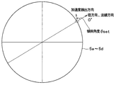
- the inclination angle ⁇ set for attaching the G sensor 22 to the wheels 5a to 5d is the radial direction of the wheels 5a to 5d when viewed from the outside of the vehicle 1 for any of the wheels 5a to 5d. Is represented by an angle formed by the detection direction of the G sensor 22 with 0 ° being a positive counterclockwise direction.
- the detection direction of the G sensor 22 is not parallel to the radial direction of the wheels 5a to 5d, but the G sensor 22 is attached to the wheel 5a so that an arbitrary inclination angle ⁇ set is attached to the radial direction. It is attached to 5d.
- the sensor transmitter 2 is attached to any of the right wheels 5a and 5c and the left wheels 5b and 5d by itself. Estimate whether it is a thing. Although details will be described later, each sensor transmitter 2 performs estimation using a calculated quadratic function, a calculated linear function, an actually measured quadratic function, and an actually measured linear function.
- the calculated quadratic function is obtained by removing the periodic component with respect to time from the acceleration obtained from the calculation and approximating the quadratic function
- the calculated linear function is obtained by removing the periodic component with respect to time from the acceleration differential value and approximating the linear function.
- the measured quadratic function is a quadratic function approximation of the median of the measured acceleration values
- the measured linear function is a linear function approximation of the median of the acceleration differential values.
- the sensor transmitter 2 is attached to any of the right wheels 5a and 5c and the left wheels 5b and 5d based on the calculated quadratic function, the calculated linear function, the measured quadratic function, and the measured primary function. Estimate.
- the calculated quadratic function and the calculated linear function are a quadratic function and an acceleration differential value that approximate the calculated acceleration that would be detected when the G sensor 22 is mounted at the inclination angle ⁇ set.
- the measured quadratic function is a quadratic function approximating the acceleration actually detected by the G sensor 22 and a linear function approximating the acceleration differential value.
- each sensor transmitter 2 is attached to any one of the front and rear wheels on the receiver 3 side.
- the sensor transmitter 2 uses the difference in the tire radius such as increase / decrease in the effective tire radius due to the load movement during acceleration / deceleration of the wheels 5a to 5d. Which of 5c and 5d is attached is detected. Thereby, wheel position detection is performed. Details of this wheel position detection will be described below.
- the microcomputer 23 estimates whether the sensor transmitter 2 itself is attached to the left or right wheel. As described above, this estimation is performed based on the estimation of the inclination angle ⁇ set , the calculation of the calculated quadratic function or the calculated linear function, the calculation of the measured quadratic function or the measured linear function, and the like.
- the estimation of the tilt angle ⁇ set and the calculation of the calculation quadratic function and calculation linear function are performed by the following method.
- the vehicle speed v (t) is expressed by Equation 1 where v 0 is the initial speed of the vehicle speed at the timing at which wheel position detection is desired, and the acceleration of the vehicle 1 at that time, in other words, the acceleration of the vehicle body 6 is a and the time is t expressed. Further, the movement distance L (t) of the vehicle 1 is expressed by Formula 2.
- the existence angle ⁇ around the axle of the G sensor 22 attached to each of the wheels 5a to 5d at that timing, that is, the current position of the G sensor 22, is expressed by the following formulas 3-1 to 3- 4 holds.
- the subscript “front” indicates the front wheel
- “rear” indicates the rear wheel
- “right” indicates the right wheel
- “left” indicates the left wheel.
- r w represents the effective tire radius of the wheels 5a to 5d.
- the inclination angle ⁇ set of the G sensor 22 with respect to each of the wheels 5a to 5d is estimated based on the equations 4-1 to 4-4.
- the fact that the acceleration of the vehicle 1 is 0 is detected based on the gravitational component of the acceleration detected by the G sensor 22.
- the gravitational component of acceleration appears as an amplitude waveform for each rotation of the wheel. When there is no change in the amplitude waveform, such as when the time interval between the maximum value and the maximum value of this amplitude waveform is constant or when the time interval between the minimum value and the minimum value is constant It is detected that the acceleration of 1 is 0.
- Equation 5 is derived.
- Equation 7 the average A avg of the maximum value and the minimum value of a sens_front_right (t) is expressed as Equation 7.
- Equation 8 the time until the minimum, when the period of the rotation and T Front_right, holds Equation 8. That is, the angle ⁇ front_right (t M) + ⁇ to that promoted angularly half period ⁇ a Set_front_right, angle theta Front_right after a lapse of a half cycle of the tire rotation from t M (t M + T front_right when taking the maximum value / 2) + ⁇ set_front_right is the same value. For this reason, the equation (8) holds. From Equation 8, it can be seen that Tfront_right is expressed as Equation 9.
- the tilt angles ⁇ set_front_left , ⁇ set_real_right , ⁇ set_real_left can be derived for the other wheels 5b to 5d by the same method. That is, the inclination angle ⁇ set can be estimated by calculation for all the G sensors 22.
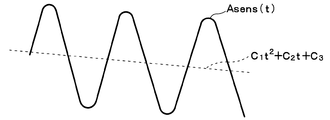
- Equations 12-1 to 12-4 a value obtained by removing a periodic function related to the time t from the acceleration a sens (t) is defined as an acceleration A sens (t). This can be expressed as Equations 12-1 to 12-4.
- Equations 12-1 to 12-4 when the acceleration a of the vehicle 1 is constant and the equations are arranged with respect to t, Equations 13-1 to 13-4 can be derived as quadratic functions of t.
- equations 4-1 to 4-4 can be expressed by the following equations: 14-1 to 14-4 can be converted.
- coefficients C1, C2, and C3 correspond to the coefficients of the calculated quadratic function. That is, the coefficient of the second-order term t 2 corresponds to C1, the coefficient of the first-order term t 1 corresponds to C2, and the coefficient of the zero- order term t 0 , that is, the constant term corresponds to C3.
- C1, C2, and C3 in the respective formulas 14-1 to 14-4 are represented by formulas, they are represented as formulas 15 to 18.
- Expressions 19-1 to 19-4 shown below can be derived.
- the acceleration differential value A sens (t) ′ which is a value obtained by removing the periodic function related to time t from the mathematical expressions 19-1 to 19-4, is expressed as the following mathematical expressions 20-1 to 20-4. Will be. It should be noted that the mathematical expressions 20-1 to 20-4 can be obtained by differentiating the above-described mathematical expressions 13-1 to 13-4 with time t.
- the equations 20-1 to 20-4 are expressed by using the equations 15-1, 15-2, 16-1, 16-2, 17-1, 17-2, 18-1, 18-2. These can be expressed as the following formulas 21-1 to 21-4.
- the function of the acceleration differential value A sens (t) ′ represented by this mathematical formula is a calculated linear function obtained by removing the periodic function related to time t from the function of the acceleration differential value a sens (t) ′ and approximating it to a linear function. is there.
- the calculation of the measured quadratic function and the measured primary function is performed by the following method.
- Formulas 21-1 to 21-4 are linear functions calculated at each wheel, the acceleration differential value A sens (t) ′, C1, C2, etc. are notated by specifying each wheel with a subscript. It is. However, for the actual acceleration A real (t) and the actual acceleration differential value A real (t) ′, C1, C2, C3, etc., the values obtained from the G sensor 22 attached to any wheel are unknown. Here, it is a general notation without subscripts. Based on the detection signal of each G sensor 22 attached to each wheel, the actual acceleration A real (t), the actual acceleration differential value A real (t) ′, C1, C2, C3, etc. are calculated. Whether or not the value is calculated based on the detection signal of the G sensor 22 is understood.
- the G sensor 22 is attached to the right wheels 5a, 5c or the left wheels 5b, 5d can be specified based on the component included in the detection signal of the G sensor 22.
- the detection signal of the G sensor 22 is proportional to the acceleration applied according to which of the left and right wheels is attached in addition to the gravitational acceleration component and the centrifugal acceleration component, that is, the acceleration caused by the attachment direction.
- Components hereinafter referred to as direction proportional components
- D a component obtained by removing the gravitational acceleration component and the centrifugal acceleration component from the detection signal of the G sensor 22 becomes the directional proportional component D sensed by the G sensor 22.
- This directional proportional component D appears with different signs depending on whether the G sensor 22 is attached to the right wheels 5a, 5c or the left wheels 5b, 5d. For this reason, by confirming the sign of the direction proportional component D, it can be specified whether the G sensor 22 is attached to the right wheels 5a, 5c or the left wheels 5b, 5d.
- the inclination angle ⁇ set is used in addition to the above-described calculation quadratic function, calculation linear function, actual measurement quadratic function, and actual measurement linear function.
- a method of calculating the direction proportional component will be described.
- the actual acceleration differential value a real (t) ′ of the actual acceleration a real (t) detected by the G sensor 22 of each wheel is calculated, and the actual acceleration differential value a real (t ) 'At least two points of the median of the amplitude.
- the average value of the local maximum value and the next local minimum value or the average value of the local minimum value and the next local maximum value can be calculated as the median value.
- These two points are two points included in the measured linear function. Therefore, for each of the two calculated points, the median value and the time t when the median value is reached are substituted into Equation 23 above.
- C1 and C2 obtained from the actual acceleration a real and the actual acceleration differential value a real (t) ′ detected by the G sensor 22 attached to each wheel are calculated. That is, by substituting the median and the time t when the median value is reached for A real (t) ′ and t in Equation 23, simultaneous equations including C1 and C2 to be obtained can be obtained. C1 and C2 can be obtained by solving simultaneous equations. Thus, C1 and C2 are specified based on the detection signal of each G sensor 22, and the actual acceleration differential value Areal (t) ′, which is a measured linear function, can be obtained.
- C3 is calculated by taking the specified C1 and C2 into Expression 22 and substituting the actual acceleration A real and time t detected by the G sensor 22 of each wheel into Expression 22.
- one median value is obtained from the maximum value and the minimum value of the actual acceleration a real (t) detected by the G sensor 22 of each wheel. This one point is one point included in the measured quadratic function. Therefore, for the calculated one point, the median value and the time t when the median value is reached are substituted into Equation 22 above.
- C3 obtained from the actual acceleration a real detected by the G sensor 22 attached to each wheel is calculated.
- C1 to C3 can be easily and accurately specified based on the detection signal of each G sensor 22, and the acceleration A sens (t), which is a calculated quadratic function specifying C1 to C3, can be obtained. Obtainable.
- a straight line connecting adjacent maximum values is obtained as a maximum value straight line, and a value on the maximum value straight line at time t when taking a minimum value located between adjacent maximum values is set as a virtual maximum value.
- the average value of the value and the minimum value can be used as the median value.
- a straight line connecting adjacent local minimum values is obtained as a local minimum straight line, and a value on the local minimum line at time t when taking a local maximum value located between adjacent local minimum values is assumed as a virtual local minimum value.
- the average value of the minimum value and the maximum value can be set as the median value.
- Equation 25 is the direction proportional component D described above, and is expressed as Equation 26.
- the formulas 24 to 26 are general expressions for all the wheels 5a to 5d. By attaching a subscript corresponding to each of the wheels 5a to 5d as a mounting position identifier, the G of each of the wheels 5a to 5d is given. The correspondence with the sensor 22 can be expressed.
- Equation 27 the expressions 27 and 28-1 are derived by taking the right front wheel 5a as an example, but the left front wheel 5b, the right rear wheel 5c and the left rear wheel 5d are also derived by the same method, and expressions 28-2 to 28 are derived. -4.
- the calculated linear function expressed by the above formulas 21-1 to 21-4 is transformed as the following formula 29. Further, by changing a part of the third expression of Expression 29 to B, it is transformed as Expression 30.
- B defined in Expression 30 is an acceleration / deceleration instruction value indicating whether the vehicle 1 is accelerating or decelerating, and is expressed as Expression 31. Since C1, C2, and C3 are represented by the above-described formulas 15 to 18, by substituting C1 and C2 in the formula 29, B is represented by the formula 32, and further, To simplify, it is expressed as Equation 33-1.
- the expressions 32 and 33-1 are derived using the right front wheel 5a as an example, but the left front wheel 5b, the right rear wheel 5c and the left rear wheel 5d are also derived by the same method, and expressions 33-2 to 33 are obtained.
- the vehicle speed V0 means the vehicle speed V when the wheel position detection is performed.
- the acceleration / deceleration instruction value B indicates when the vehicle speed becomes zero. That is, as shown in Expression 30, when the time t becomes ⁇ B, the vehicle speed becomes zero. If -B is a positive value, it indicates that the timing is later than the current time, that is, the vehicle speed will be zero in the future. If -B is a negative value, the timing is earlier than the current time. That is, it indicates that the vehicle speed has been zero in the past. In the future, when the vehicle speed becomes 0, the vehicle 1 is decelerating and deceleration is occurring at this time, so the acceleration a is a negative value, and the vehicle speed has been 0 in the past. At this time, since the vehicle 1 is accelerating and generating an acceleration, the acceleration a is a positive value. Therefore, it is possible to grasp whether the vehicle 1 is accelerating or decelerating based on the acceleration / deceleration instruction value B.
- the vehicle speed V0 is a positive value.
- the acceleration / deceleration instruction value B is expressed as Equation 32 and is obtained by substituting C1 and C2. Therefore, in the equations 33-1 to 33-4, the vehicle speed V0 becomes a positive value, and the sign of the acceleration / deceleration instruction value B can be confirmed by obtaining the acceleration / deceleration instruction value B by substituting C1 and C2. Whether the sign of a is positive or negative can be determined.
- the inclination angle ⁇ set of the G sensor 22 with respect to the wheels 5a to 5d can be estimated based on the equations 4-1 to 4-4. Therefore, in Equations 28-1 to 28-4, r w indicates the effective tire radius at the wheels 5a to 5d and is a positive value, and the sign of the acceleration a can be determined as described above. For this reason, if the estimated value is used for the inclination angle ⁇ set , the sign of the direction proportional component D can be obtained. Based on the sign of the direction proportional component D, it can be specified whether the sensor transmitter 2 including the G sensor 22 is attached to the right wheels 5a and 5c or the left wheels 5b and 5d. .
- the direction proportional component D is represented by C1 to C3. Therefore, the direction proportional component D can also be calculated by calculating C1 to C3. Further, the direction proportional component D is also expressed by Equations 28-1 to 28-4. These expressions are collectively expressed as the following Expression 34.
- This equation 34 the direction proportional component D which is calculated by substituting the C1 ⁇ C3 respect Equation 26, the estimated value of the inclination angle theta The set, as well as substitutes the effective tire radius r w, determined already in the acceleration a
- the sign it is possible to determine whether the sign on the right side of Expression 34 is positive or negative. For example, when tan ⁇ set is a positive value, the sign of the right side of Expression 34 becomes positive if the sign of the direction proportional component D and acceleration a is the same based on the fact that the equation of Expression 34 holds. If the signs are different, the sign on the right side of Equation 34 is negative.
- Expression 34 The sign on the right side of Expression 34 is positive when the sensor transmitter 2 is attached to the right wheels 5a and 5c, and the sign is negative when the sensor transmitter 2 is attached to the left wheels 5b and 5d. It is a case where it is attached to. Based on this, it is possible to determine whether the sensor transmitter 2 is attached to the right wheels 5a, 5c or the left wheels 5b, 5d.
- tan ⁇ set obtained based on the estimated value of the tilt angle ⁇ set is a positive value
- the sensor transmitter 2 is attached to the left wheels 5b and 5d, and if the signs are different, the sensor transmitter 2 is attached to the left wheels 5b and 5d. Can be determined.
- a frame including the estimation result and data such as a value obtained at the time of estimation is sent from the sensor transmitter 2. This is transmitted and received by the receiver 3.
- the receiver 3 Based on the estimation result stored in the frame, the receiver 3 specifies whether the sensor transmitter 2 that transmitted the frame is attached to either the left or right wheel. Furthermore, the receiver 3 specifies whether the sensor transmitter 2 is attached to any of the front and rear wheels based on the value obtained at the time of estimation stored in the frame.
- a / rw related to the effective tire radius is stored in the frame as a value obtained at the time of estimation. Based on the value of a / rw related to the effective tire radius, it is specified which of the front and rear wheels the sensor transmitter 2 is attached to.
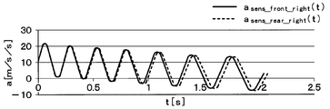
- the measured value of the G sensor 22 varies depending on which of the front and rear wheels the sensor transmitter 2 is attached. If it is the G sensor 22 of the sensor transmitter 2 attached to the right front and rear wheels 5a and 5c, the measured value is as shown in the waveform of FIG. As shown in this figure, in the sensor transmitter 2 attached to the right front and rear wheels 5a and 5c, the difference in amplitude is difficult to occur because it is arranged on the same side of the vehicle 1, but the effective tire radius A phase difference corresponding to the difference occurs. Generally, since the effective tire radius is smaller on the front wheel side than on the rear wheel side, the phase of the amplitude of the G sensor 22 is earlier on the front wheel side than on the rear wheel side.
- the vehicle 1 has different tire radii between the front wheels 5a, 5b and the rear wheels 5c, 5d, there is a difference in the effective tire radius from the beginning, so that a phase difference appears in the waveform of the measured value based on the effective tire radius. Based on this, it is possible to identify the sensor transmitter 2 attached to any of the front and rear wheels. Even if the tire radii at rest are not different, a difference in effective tire radius occurs between the front wheels 5a and 5b and the rear wheels 5c and 5d due to load movement during acceleration / deceleration of the vehicle 1. For this reason, it is possible to identify the sensor transmitter 2 attached to any of the front and rear wheels based on the difference in effective tire radius.
- the receiver 3 compares the value of a / rw related to the effective tire radius between the sensor transmitters 2 including the data of the estimation result that the receiver 3 is attached to the right wheels 5a and 5c. Then, it is specified that the sensor transmitter 2 that has transmitted the smaller data is attached to the right front wheel 5a, and the sensor transmitter 2 that has transmitted the larger data is attached to the right rear wheel 5c. Identify as a thing. Similarly, the value of a / rw related to the effective tire radius between the sensor transmitters 2 including the data of the estimation result that it is attached to the left wheels 5b and 5d is compared in magnitude. Then, it is specified that the sensor transmitter 2 that has transmitted the smaller data is attached to the left front wheel 5b, and the sensor transmitter 2 that has transmitted the larger data is attached to the left rear wheel 5d. Identify as a thing.
- a / rw during acceleration and deceleration is stored in the sensor transmitter 2 itself, and the absolute value thereof is compared to determine which of the front and rear wheels is mounted by the sensor transmitter 2 itself. You can also. Specifically, if the absolute value of a / rw during acceleration, i.e. a> 0, is smaller than the absolute value of a / rw during deceleration, i.e. a ⁇ 0, it can be determined that the vehicle is mounted on the front wheel. Whether the vehicle is accelerating or decelerating can be determined by the sign of a / rw.
- the sensor transmitter 2 itself, the inclination angle theta
- the set calculates, based on the calculated quadratic function and calculate a linear function and the measured quadratic function and the measured first order function in addition to the inclination angle theta
- the set It is estimated which of the right wheels 5a and 5c and the left wheels 5b and 5d is attached. Based on the estimation result and the effective tire radius, it is specified on the receiver 3 side whether each sensor transmitter 2 is attached to both the front wheels 5a and 5b and the both rear wheels 5c and 5d. This makes it possible to specify which of the wheels 5a to 5d the sensor transmitter 2 is attached to.
- Such a wheel position detection method does not require additional equipment such as a trigger machine, and can prevent the apparatus configuration from becoming complicated and costly. Moreover, there are few restrictions on the mounting position of the receiver 3 or the receiving antenna 31. Further, a special sensor called a biaxial G sensor is not required. Further, it is possible to discriminate between a steered wheel and a driven wheel. And since the information of the wheel speed sensor used for ABS control is not used, the communication specification is not complicated, and it is possible to detect the wheel position with high accuracy without requiring the tire air pressure detection accuracy. .
- the differential value da / dt of the acceleration a of the right front wheel 5a is extracted from FIG. 9A, and the median value of the differential values da / dt of the acceleration a is obtained based on the maximum value and the minimum value. Results.
- a straight line connecting the medians becomes a straight line indicating a measured linear function. Further, when the straight line indicating the measured linear function and the median value of the acceleration a are shown in the figure, the result is as shown in FIG. 11A.
- Equation 23 the median value of the differential value da / dt of acceleration a at the two points and the time t at the median value are substituted into Equation 23 using two points in the straight line indicating the measured linear function.
- C1_front_right and C2_front_right series equations are obtained.
- C1_front_right and C2_front_right are calculated by solving them.
- one median is obtained from the acceleration a in FIG. 8A, and the median and the time t at the median are substituted into Equation 22.
- C1_front_right and C2_front_right obtained previously are substituted.
- C3_front_right is calculated.
- C1_front_right is 0.6912
- C2_front_right is ⁇ 6.313
- C3_front_right is 12.23.
- B front_right is calculated to be ⁇ 4.567 using Expression 33-1 and tan ( ⁇ set_front_right ) is 11.43 when ⁇ set_front_right is 85 °. Therefore, when D front_right is calculated using Equation 28-1, it is 3.163. Also, D front_right / tan ( ⁇ set_front_right ) was ⁇ 0.2768.
- the sensor transmitter 2 provided in the right front wheel 5a calculates each value based on the detection signal of the G sensor 22, the value is calculated as described above. For this reason, the acceleration a ⁇ 0 is estimated based on the calculated B. Furthermore, since tan ⁇ set is positive, the direction proportional component D ⁇ 0, and the signs of the acceleration a and the direction proportional component D are the same, the sensor transmitter 2 is attached to the right wheel. It can be determined that they are 5a and 5c.
- the acceleration a ⁇ 0 can be estimated based on the calculated B. Further, since tan ⁇ set is positive and the directional proportional component D> 0 and the signs of the acceleration a and the directional proportional component D are different, the sensor transmitter 2 is attached to the left wheel. It can be determined as 5b and 5d.
- C1_rear_right is 0.6535
- C2_rear_right is ⁇ 6.085
- C3_rear_right is 11.76
- B rear_right is ⁇ 4.656
- D rear_right is ⁇ 3.683
- r tan ( ⁇ set_rear_right ) was ⁇ 0.3223. Therefore, the acceleration a ⁇ 0 can be estimated based on the calculated B. Furthermore, since tan ⁇ set is positive, the direction proportional component D ⁇ 0, and the signs of the acceleration a and the direction proportional component D are the same, the sensor transmitter 2 is attached to the right wheel. It can be determined that they are 5a and 5c.
- a frame including the estimation result and data such as a value obtained at the time of estimation is transmitted from the sensor transmitter 2. This is received by the receiver 3. Then, in the receiver 3, based on the estimation result stored in the frame, it is specified whether the sensor transmitter 2 that transmitted the frame is attached to either the left or right wheel. Furthermore, the receiver 3 specifies whether the sensor transmitter 2 is attached to any of the front and rear wheels based on the value obtained at the time of estimation stored in the frame. This makes it possible to specify which of the wheels 5a to 5d is attached to each sensor transmitter 2.
- the reception antenna 31 is a single common antenna.
- a form in which a plurality of reception antennas 31 are provided corresponding to each of the wheels 5a to 5d, for example, may be used.
- the reception antenna 31 is a common antenna, it is particularly effective when the reception antenna 31 is a shared antenna because it is difficult to identify the wheels 5a to 5d to which the sensor transmitter 2 is attached.
- the data indicating the result of the wheel position detection is stored in a frame in which information related to the tire pressure is stored and transmitted.
- this is merely an example of a frame configuration, and a frame that stores data indicating the result of wheel position detection and a frame that stores information related to tire pressure may be separate frames.
- a common frame capable of both wheel position detection and tire air pressure detection can be obtained.
- the value a / rw related to the effective tire radius is used as an example of a method for detecting whether the sensor transmitter 2 is attached to the front wheels 5a, 5b or the rear wheels 5c, 5d.
- the case of using was given as an example.
- a method other than the method described in the above embodiment may be adopted.
- the detection result of acceleration by the G sensor 22 is stored in a frame, and the phase of the acceleration waveform indicated by the G sensor 22 of the sensor transmitter 2 attached to the right wheels 5a, 5c or the left wheels 5b, 5d is compared.
- it may be specified which wheel is the front or rear.
- a / rw is stored in the frame as a value related to the effective tire radius
- the effective tire radius itself may be stored as a value related to the effective tire radius.
- the sign of the acceleration a is determined based on the fact that the vehicle 1 is moving forward at most timings at which the wheel position is detected.
- the sign of the acceleration a can be determined by another method. For example, when the period of the amplitude waveform indicated by the detection signal of the G sensor 22 tends to decrease, the tire rotation period becomes shorter during acceleration, and conversely when it tends to increase, the tire rotation period becomes longer during deceleration. Can be determined. For this reason, for example, the period of the amplitude waveform is obtained from the time interval between the maximum values or the minimum values, and it is determined whether the sign of the acceleration a is positive or negative based on whether the amplitude waveform is decreasing or expanding. You can also.
Landscapes
- Engineering & Computer Science (AREA)
- Mechanical Engineering (AREA)
- Physics & Mathematics (AREA)
- General Physics & Mathematics (AREA)
- Measuring Fluid Pressure (AREA)
Abstract
センサ送信機(2)自身で、車輪(5a~5d)に対するGセンサ(22)の取り付けの傾斜角度(θset)を演算し、計算2次関数と計算1次関数および実測2次関数と実測1次関数に基づいて、右車輪(5a、5c)と左車輪(5b、5d)のいずれに取り付けられたものであるかを推定する。そして、その推定結果および実効タイヤ半径に基づいて、受信機(3)側で各センサ送信機(2)が両前輪(5a、5b)と両後輪(5c、5d)のいずれに取り付けられたものであるかを特定する。これにより、センサ送信機(2)が車輪(5a~5d)のいずれに取り付けられたものであるかを特定することが可能となる。
Description
本出願は、2017年1月11日に出願された日本特許出願番号2017-2723号に基づくもので、ここにその記載内容が参照により組み入れられる。
本開示は、車輪が車両のどの位置に取り付けられているかを検出するセンサ送信機や車輪位置検出装置に関するもので、特に、タイヤ空気圧の検出を行うタイヤ空気圧検出装置に適用すると好適である。
従来より、タイヤ空気圧検出装置(以下、TPMS:Tire Pressure Monitoring Systemという)の1つとして、ダイレクト式のものがある。このタイプのTPMSでは、タイヤが取り付けられた車輪側に、圧力センサ等のセンサが備えられたセンサ送信機が直接取り付けられている。また、車体側には、アンテナおよび受信機が備えられており、センサからの検出信号がセンサ送信機から送信されると、アンテナを介して受信機にその検出信号が受信され、タイヤ空気圧の検出が行われる。
このようなダイレクト式のTPMSでは、データ送信を行うセンサ送信機がどの車輪に取り付けられたものかを判別できるようにする必要がある。このため、例えば下記の(1)~(6)に示すような様々な方法によって、センサ送信機が取り付けられた車輪を検出する車輪位置検出が行われている。
(1)センサ送信機にトリガ信号の受信機能を持たせ、トリガ信号を受信したときの受信強度を示したデータを受信機側に伝えるという双方向通信を行うことで、車輪位置検出を行っている。具体的には、各センサ送信機から異なる距離となるようにトリガ機を配置し、トリガ機からトリガ信号を出力すると、各センサ送信機でトリガ信号が異なった受信強度で測定されるようにしている。この受信強度の相違に基づいて、車輪位置検出を行っている。
(2)各センサ送信機からの距離が異なる距離となるように車体側の受信機を配置する手法もある。すなわち、センサ送信機が送信するRF(Radio Frequency)信号の信号強度を受信機側で測定し、その測定結果と、各センサ送信機と受信機との間の距離と予め測定しておいた受信強度パターンとの関係に基づいて、車輪位置検出を行うことができる。
(3)センサ送信機に車輪の回転方向と径方向の加速度を検出できる2軸の加速度センサ(以下、Gセンサという)を備える手法もある(例えば、特許文献1参照)。車輪の回転方向で各軸のGセンサの検出信号の位相差が変わることから、受信機でその位相差を比較することにより送信機が左右いずれの車輪に取り付けられたものであるかを判別し、車輪位置検出を行っている。
(4)操舵輪の方が従動輪よりも移動距離が長くなることを利用して、前後輪のいずれに設置されたセンサ送信機であるかを特定するという車輪位置検出の手法もある。回転するタイヤの遠心力が車輪速度に比例することから、Gセンサによって検出した車輪の遠心力を積分することでタイヤの移動距離と比例する値を生成する。この値を受信機が受け取り、タイヤの移動距離が長い方を操舵輪、短い方を従動輪と判定している。
(5)アンチロックブレーキ(以下、ABSという)制御に用いている車輪速度センサの歯車情報を用いて車輪位置検出を行う手法もある。具体的には、センサ送信機に備えたGセンサの加速度検知信号に基づいて車輪が所定の回転位置(回転角度)になったことを検出し、車輪側からフレーム送信を行わせる。そして、車輪と連動して回転させられる歯車の歯の通過を車輪速度センサで検出し、フレームの受信タイミングでの歯位置が車輪毎にほぼ一定になることを利用して、歯位置のバラツキ幅に基づいて、車輪位置検出を行っている。
(6)受信機でセンサ送信機から送られてくるタイヤ空気圧に関する情報を受信して、タイヤ空気圧の変化を測定すると共に、そのときの車両の加速度を測定し、タイヤ空気圧の変化が車両の加速度に応じた値となることに基づいて車輪位置検出を行う手法もある。
しかしながら、(1)の手法では、トリガ機などの追加の設備が必要になるため、装置構成の複雑化を招くし、コスト増にも繋がる。(2)の手法では、受信機、もしくは受信アンテナの搭載位置に制約が発生し、車両適合を加味すると、その搭載位置が更に限定されてしまう。(3)の手法では、2軸のGセンサという特殊なセンサが必要になる。(4)の手法では、タイヤ径が前後輪で異なっている場合、操舵輪と従動輪との判別が難しく、誤判定を招く。(5)の手法では、ABS制御に用いる車輪速度センサの情報を利用するため、車輪位置検出装置、もしくはタイヤ空気圧検出装置との通信仕様が複雑になる。(6)の手法では、タイヤ空気圧の検出精度を出すことが難しいため、精度良い車輪位置検出を行えない。
本開示は、トリガ機などの追加の設備や2軸のGセンサを必要とせず、搭載位置の制約も少なく、通信仕様の複雑化を招かなくても、的確に車輪位置検出を行うことができるセンサ送信機、車輪位置検出装置およびそれを用いたタイヤ空気圧検出装置を提供することを目的とする。
上記目的を達成するため、請求項1に記載の車輪位置検出装置では、第1制御部において、加速度センサで検出した加速度に基づいて、加速度センサが径方向に対して周方向にずらされた角度に相当する傾斜角度を演算し、車輪に対して傾斜角度で加速度センサが取り付けられている場合における加速度の計算値の振幅の中央値を2次関数で近似した計算2次関数と、加速度の計算値の微分値の中央値を1次関数で近似した計算1次関数と、加速度センサで実際に検出される値の振幅の中央値を2次関数で近似した実測2次関数と、加速度センサで実際に検出される値の微分値の中央値を1次関数で近似した実測1次関数とに基づいて、該第1制御部が備えられたセンサ送信機自身が取り付けられたのが右車輪と左車輪のいずれであるかを推定する。
すなわち、実測2次関数における2次の項の係数をC1、1次の項をC2、定数項をC3として、実測1次関数中の2点における中央値および該中央値となる時間に基づいてC1およびC2を算出すると共に、算出されたC1およびC2と実測2次関数中の1点における中央値および該中央値となる時間に基づいてC3を算出する。さらに、車体の加速度をa、車速の初速度をv0、傾斜角度をθset、車両が加速中であるか減速中であるかを示す加減速指示値をB、加速度センサの検知結果から重力加速度成分と遠心加速度成分を取り除いた方向比例成分をDとし、v0の符号を正として、Bの関係式であるB=C2/C1=v0/aに加えて算出したC1およびC2に基づいてaの符号が正か負のいずれであるかを判定すると共に、Dの関係式であるD=-(C2/2C1)2+C3/C1に加えて算出したC1とC2およびC3に基づいてDを算出する。そして、θsetから算出されるtanθsetの符号とaとDの符号が同じであるか否かに基づいて、センサ送信機自身が取り付けられたのが右車輪と左車輪のいずれであるかを推定する。
このように、センサ送信機自身で、傾斜角度を演算し、この傾斜角度に加えて計算2次関数や計算1次関数および実測2次関数や実測1次関数に基づいて、右車輪と左車輪のいずれに取り付けられたものであるかを推定している。このような車輪位置検出手法においては、トリガ機などの追加の設備が必要にならず、装置構成の複雑化、コスト増を防ぐことができる。また、受信機、もしくは受信アンテナの搭載位置の制約も少ない。また、2軸のGセンサという特殊なセンサを必要としない。さらに、操舵輪と従動輪との判別も可能である。そして、ABS制御に用いる車輪速度センサの情報を利用しないため、通信仕様の複雑化を招くこともないし、タイヤ空気圧の検出精度が要求されることなく精度良い車輪位置検出を行うことが可能となる。
以下、本開示の実施形態について図に基づいて説明する。なお、以下の各実施形態相互において、互いに同一もしくは均等である部分には、同一符号を付して説明を行う。
(第1実施形態)
本開示の第1実施形態について説明する。本実施形態では、図1に示すタイヤ空気圧検出装置に車輪位置検出装置としての機能を持たせたものについて説明するが、車輪位置検出装置のみの構成としても良い。なお、図1の紙面上下方向が車両1の前後方向、紙面左右方向が車両1の左右方向に一致する。この図を参照して、本実施形態におけるタイヤ空気圧検出装置について説明する。
本開示の第1実施形態について説明する。本実施形態では、図1に示すタイヤ空気圧検出装置に車輪位置検出装置としての機能を持たせたものについて説明するが、車輪位置検出装置のみの構成としても良い。なお、図1の紙面上下方向が車両1の前後方向、紙面左右方向が車両1の左右方向に一致する。この図を参照して、本実施形態におけるタイヤ空気圧検出装置について説明する。
図1に示すように、タイヤ空気圧検出装置は、車両1に取り付けられるもので、センサ送信機2、受信機3および表示器4を備えて構成されている。
図1に示すように、センサ送信機2は、車両1における各車輪5a~5dに取り付けられるものであり、本実施形態の場合、4つの車輪5a~5dそれぞれにセンサ送信機2a~2dが備えられている。センサ送信機2a~2dは、車輪5a~5dに取り付けられたタイヤの空気圧を検出すると共に、その検出結果を示すタイヤ空気圧に関する情報をフレーム内に格納してRF送信する。一方、受信機3は、車両1における車体6側に取り付けられる。受信機3は、センサ送信機2a~2dから送信されたフレームをRF受信すると共に、その中に格納された検出信号に基づいて各種処理や演算等を行うことで車輪位置検出およびタイヤ空気圧検出を行う。図2(a)および図2(b)を参照して、センサ送信機2a~2dおよび受信機3の構成について説明する。
図2(a)に示すように、センサ送信機2は、センシング部21、Gセンサ22、マイクロコンピュータ23、送信部24、電池25および送信アンテナ26を備えた構成となっており、電池25からの電力供給に基づいて各部が駆動される。
センシング部21は、例えばダイアフラム式の圧力センサ21aや温度センサ21bを備えた構成とされ、タイヤ空気圧に応じた検出信号や温度に応じた検出信号を出力する。Gセンサ22は、一方向の加速度を検出するものである。本実施形態においては、Gセンサ22にて、各車輪5a~5dの径方向、つまり、周方向に対する法線方向に対して周方向に任意の角度ずらした方向の加速度が検出されるように、Gセンサ22の取り付け角度を調整している。これについては、後述する。
マイクロコンピュータ23は、第1制御部に相当する制御部などを備えた周知のもので、制御部内のメモリに記憶されたプログラムに従って、車輪位置検出処理やタイヤ空気圧検出処理を含む所定の処理を実行する。制御部内のメモリには、各センサ送信機2a~2dを特定するためのセンサ送信機固有の識別情報と自車両を特定するための車両固有の識別情報とを含む個別のID情報が格納されている。また、制御部内のメモリには、車輪位置検出に用いるデータとして、例えばセンサ送信機2が取り付けられた車輪のリム径が記憶されている。リム径については、センサ送信機2の製造時にメモリに記憶しておいても良いし、車輪5a~5dへの装着時に、通信機器を用いて自動車整備工場などで書き込むようにしても良い。勿論、センサ送信機2と受信機3との間で双方向通信が行える形態とされている場合には、ユーザが表示器4を操作することなどによって受信機3を介してリム径のデータが制御部内のメモリに記憶されるようにしても良い。
マイクロコンピュータ23は、センシング部21からのタイヤ空気圧に関する検出信号を受け取り、それを信号処理すると共に必要に応じて加工し、そのタイヤ空気圧に関する情報を各センサ送信機2a~2dのID情報と共にフレーム内に格納する。また、マイクロコンピュータ23は、例えば検出された加速度が所定の閾値を超えたときに走行中と判定し、走行中と判定した後に短周期で加速度サンプリングを行う。そして、マイクロコンピュータ23は、検出した加速度に基づいて車両1の速度(以下、車速という)が一定速度であることを検出したときに、Gセンサ22の取り付け角度演算を行う。このとき、走行中と判定した後に、一定の時間が経過してから短周期での加速度サンプリングを行うようにすると、車速が安定した状態で行えるため好ましい。さらに、マイクロコンピュータ23は、Gセンサ22の取り付け角度演算を演算すると、Gセンサ22が検出した実際の加速度に基づいて、センサ送信機2自身が取り付けられているのがどの車輪であるかを推定する。この推定は、減速時に行うと好ましい。すなわち、減速時には短周期での加速度サンプリングにおいて大きな加速度変化を得ることができ、より精度良い車輪位置検出が可能になるため好ましい。ここでは、マイクロコンピュータ23により、自身のセンサ送信機2の取り付けられたのが右車輪5a、5cと左車輪5b、5dのいずれであるかを推定している。そして、マイクロコンピュータ23は、自身のセンサ送信機2が右車輪5a、5cと左車輪5b、5dのいずれに取り付けられているかの推定結果や推定の際に得られた値等を示すデータをタイヤ空気圧に関するデータが格納されたフレームに格納している。なお、このマイクロコンピュータ23で行われる車輪位置の推定の詳細については後で説明する。
また、マイクロコンピュータ23は、フレームを作成すると、送信部24を介して送信アンテナ26より受信機3に向けて送信している。このフレームを受信機3に向けて送信する処理も、上記プログラムに従って行われる。例えば、所定の送信周期毎に繰り返しフレーム送信を行うようにしている。
送信部24は、送信アンテナ26を通じて、マイクロコンピュータ23から送られてきたフレームを受信機3に向けて送信する出力部としての機能を果たす。送信に使用する電波としては、例えばRF帯の電波を用いている。
電池25は、マイクロコンピュータ23などに対して電力供給を行うものである。この電池25からの電力供給を受けて、センシング部21でのタイヤ空気圧に関するデータの収集やGセンサ22での加速度検出およびマイクロコンピュータ23での各種演算などが実行される。
このように構成されるセンサ送信機2a~2dは、例えば、各車輪5a~5dのホイールにおけるエア注入バルブに取り付けられ、センシング部21がタイヤの内側に露出するように配置される。つまり、各車輪5a~5dの回転中心からリム径に応じた距離、具体的にはリム径の半分の距離だけ離れた位置にセンサ送信機2a~2dが取り付けられている。これにより、該当するタイヤ空気圧を検出し、各センサ送信機2a~2dに備えられた送信アンテナ26を通じて、所定の送信タイミングの際にフレームを送信することで、受信機3側にタイヤ空気圧に関する信号を定期送信するようになっている。
一方、受信機3は、受信アンテナ31と受信部32およびマイクロコンピュータ33を備えた構成とされている。
受信アンテナ31は、各センサ送信機2から送られてくるフレームを総括的に受け取る1本の共通アンテナとなっており、車体6に固定されている。
受信部32は、各センサ送信機2から送信されたフレームが受信アンテナ31で受信されると、それを入力してマイクロコンピュータ33に送る入力部としての機能を果たすものである。
マイクロコンピュータ33は、第2制御部に相当するものであり、CPU、ROM、RAM、I/Oなどを備えた周知のマイクロコンピュータによって構成され、ROMなどに記憶されたプログラムに従って、所定の処理を実行する。
まず、マイクロコンピュータ33は、各センサ送信機2a~2dからの送信フレームを用いて、マイクロコンピュータ33内のメモリに記憶されたプログラムに従って車輪位置検出処理を実行する。これにより、各センサ送信機2a~2dが車輪5a~5dのいずれに取り付けられたものかを特定する車輪位置検出が行われる。すなわち、各センサ送信機2a~2dからの送信フレームに格納された各センサ送信機2が取り付けられたのが右車輪5a、5cと左車輪5b、5dのいずれであるかの推定結果や推定の際に得られた値等を示すデータを読み出す。そして、マイクロコンピュータ33は、その推定結果を示すデータに基づいてセンサ送信機2が左右いずれの車輪に取り付けられているかを特定し、さらにや推定の際に得られた値等を示すデータに基づいて前後いずれの車輪に取り付けられているかを特定する。そして、その特定結果に基づいて、各センサ送信機2a~2dのID情報と各センサ送信機2a~2dが取り付けられている各車輪5a~5dの位置とを関連づけて記憶する。
その後は、マイクロコンピュータ33は、各センサ送信機2a~2dからフレームが送信されてきたときに、そのフレーム内に格納されたID情報およびタイヤ空気圧に関するデータに基づいて、各車輪5a~5dのタイヤ空気圧検出を行う。このとき、既にID情報と各センサ送信機2a~2dが取り付けられている各車輪5a~5dの位置とを関連づけて記憶してあるため、車輪5a~5dのいずれであるかを特定して、各車輪5a~5dのタイヤ空気圧検出を行うことができる。
表示器4は、図1に示されるように、ドライバが視認可能な場所に配置され、例えば車両1におけるインストルメントパネル内に設置される警報ランプによって構成される。この表示器4は、例えば受信機3におけるマイクロコンピュータ33からタイヤ空気圧が低下した旨を示す信号が送られてくると、その旨の表示を行うことでドライバにタイヤ空気圧の低下を報知する。
続いて、各センサ送信機2に備えられるGセンサ22を用いた車輪位置検出について、図3および図4を用いて説明する。
各センサ送信機2に取り付けられたGセンサ22は、センサ送信機2と共に各車輪5a~5dに取り付けられている。以下の説明では、図3のように、Gセンサ22の車軸周りの存在角度θについては、車両1の前方を0°とし、右車輪5a、5cだけでなく左車輪5b、5dについても、車両1の右側面から見て、車輪5a~5dの中心に対する反時計回りを正とする。また、図4のように、車輪5a~5dに対するGセンサ22の取り付けの傾斜角度θsetについては、車輪5a~5dのいずれについても、車両1の外側から見て、車輪5a~5dの径方向を0°とし、反時計方向を正として、Gセンサ22の検出方向のなす角度で表す。
本実施形態では、Gセンサ22の検出方向を車輪5a~5dの径方向と平行にするのではなく、径方向に対して任意の傾斜角度θsetが付けられるようにしてGセンサ22を車輪5a~5dに取り付けている。このような取り付け方としておき、この傾斜角度θsetを推定によって既知としておくことで、各センサ送信機2は、自分自身で、右車輪5a、5cと左車輪5b、5dのいずれに取り付けられたものであるかを推定する。詳細は後述するが、各センサ送信機2は、計算2次関数、計算1次関数、実測2次関数および実測1次関数を用いて推定している。計算2次関数は、計算から得られる加速度から時間に対する周期成分を取り除き2次関数近似したものであり、計算1次関数は、加速度微分値から時間に対する周期成分を取り除き1次関数近似したものである。実測2次関数は、加速度の実測値の中央値を2次関数近似したものであり、実測1次関数は、その加速度微分値の中央値を1次関数近似したものである。そして、計算2次関数、計算1次関数、実測2次関数および実測1次関数に基づいて、センサ送信機2が右車輪5a、5cと左車輪5b、5dのいずれに取り付けられたものであるかを推定する。
なお、計算2次関数および計算1次関数は、Gセンサ22が傾斜角度θsetで取り付けられている場合に、検出されるであろう計算上の加速度を近似した2次関数と加速度微分値を近似した1次関数である。実測2次関数は、実際にGセンサ22で検出された加速度を近似した2次関数および加速度微分値を近似した1次関数である。
さらに、センサ送信機2で自身が左右のいずれの車輪に取り付けられたものであるかを特定すると、受信機3側において、各センサ送信機2が前後のいずれの車輪に取り付けられたものであるかを特定する。具体的には、受信機3では、車輪5a~5dの加減速中の荷重移動による実効タイヤ半径の増減など、タイヤ半径の相違を利用して、センサ送信機2が前輪5a、5bと後輪5c、5dのいずれに取り付けられたものであるかを検出する。これによって、車輪位置検出を行っている。以下、この車輪位置検出の詳細について説明する。
最初に、マイクロコンピュータ23にて、センサ送信機2自身が左右いずれの車輪に取り付けられているかを推定する。上記したように、この推定については、傾斜角度θsetの推定と、計算2次関数や計算1次関数の算出および実測2次関数や実測1次関数の算出などに基づいて行っている。
まず、傾斜角度θsetの推定と、計算2次関数や計算1次関数の算出については、次のような手法によって行っている。
車速v(t)は、車輪位置検出を行いたいタイミングでの車速の初速度をv0、そのときの車両1の加速度、換言すれば車体6の加速度をa、時間をtとして、数式1で表される。また、車両1の移動距離L(t)については、数式2で表される。
そして、そのタイミングでの各車輪5a~5dそれぞれに取り付けられたGセンサ22の車軸周りの存在角度θ、つまりGセンサ22の現在位置については、円弧法表記で次の数式3-1~3-4が成り立つ。なお、以下の説明において、添え字の“front”は前輪、“rear”は後輪であることを示し、“right”は右輪、“left”は左輪であることを示している。θ0は、t=0のとき、つまり車輪位置検出の開始のときにおけるGセンサ22の車軸周りの存在角度θを示している。rwは、車輪5a~5dにおける実効タイヤ半径を示している。

また、rrを車輪5a~5dにおけるタイヤのリム径とすると、各車輪5a~5dの傾斜角度θsetを用いて、Gセンサ22の計測値asensの基本式を表すことができる。

ここで、数式4-1~4-4に基づいて、各車輪5a~5dに対するGセンサ22の傾斜角度θsetを推定する。傾斜角度θsetの推定は、車両1の加速度が0、つまりa=0のときに行われる。車両1の加速度が0であることについては、Gセンサ22で検出される加速度の重力成分に基づいて検出している。加速度の重力成分は、車輪一回転毎に振幅波形として表れる。この振幅波形の極大値と極大値との間の時間間隔が一定である場合、もしくは、極小値と極小値との間の時間間隔が一定になる場合など、振幅波形に変化が無いときを車両1の加速度が0であると検出している。
例えば、右前輪5aにおいて車両1の加速度が0の場合を想定して、数式4-1中の加速度aに0を代入すると、数式5が導出される。
また、加速度a=0のときに、車速v(t)は一定となるため、v(t)=vとすると、数式5より数式6が導出される。
この数式6より、asens_front_right(t)の極大値と極小値の平均Aavgは、数式7のように表されることになる。
ここで、数式6で示したasens_front_right(t)が極大となるときの時間tをtMとし、その後、極小となるまでの時間について、回転の周期をTfront_rightとすると、数式8が成り立つ。すなわち、極大値をとるときの角度θfront_right(tM)+θset_front_rightを角度的に半周期π進めたものと、tMからタイヤ回転の半周期を経過した後の角度θfront_right(tM+Tfront_right/2)+θset_front_rightは同じ値になる。このため、数式8の等式が成り立つ。そして、数式8より、Tfront_rightが数式9のように表されることが判る。
asens_front_right(t)の極大値と極小値の平均Aavg、つまりasens_front_right(t)の中央値は、遠心力rr(2π/Tfront_right)と、Gセンサ22の傾斜角度θset_front_rightより、数式10のように表すことができる。したがって、傾斜角度θset_front_rightは、数式11のように導出することができる。


なお、ここでは右前輪5aを例に挙げて説明したが、他の車輪5b~5dについても同様の手法によって、傾斜角度θset_front_left、θset_rear_right、θset_rear_leftを導出することができる。すなわち、全Gセンサ22について、傾斜角度θsetを演算により推定することができる。
さらに、数式4-1~4-4で示したGセンサ22の計測値asensの基本式において、加速度asens(t)から時間tに関する周期関数を取り除いた値を加速度Asens(t)と表記すると、数式12-1~12-4のようになる。

そして、数式12-1~12-4において、車両1の加速度aを一定として、tについて式を整理すると、tの2次関数として数式13-1~13-4を導出することができる。

この数式13-1~13-4は、車輪5a~5dの回転に伴う周期成分を取り除いた式であることから、図5に示すように、車輪5a~5dの回転に伴って振幅する加速度Asens(t)の振幅の中央値を2次関数で表した式になる。これが、基本式より計算により導出される加速度Asens(t)を表す計算2次関数となる。
また、上記した数式13-1~13-4で示される加速度Asens(t)の計算2次関数において、係数をC1、C2、C3とすると、数式4-1~4-4を以下の数式14-1~14-4のように変換することができる。

これら各係数C1、C2、C3が、計算2次関数の各係数に相当する。つまり、2次の項であるt2の係数がC1、1次の項であるt1の係数がC2、0次の項であるt0の係数、つまり定数項がC3に相当している。数式14-1~14-4それぞれにおけるC1、C2、C3を数式で表すと、数式15~18のように表される。


また、数式4-1~4-4の基本式を時間tで微分すると、次に示す数式19-1~19-4を導出することができる。

そして、この数式19-1~19-4から時間tに関する周期関数を取り除いた値である加速度微分値Asens(t)’は、次に示す数式20-1~20-4のように表されることになる。なお、上記した数式13-1~13-4について、時間tで微分しても、数式20-1~20-4を得ることができる。

このとき、数式20-1~20-4は、上記した数式15-1、15-2、16-1、16-2、17-1、17-2、18-1、18-2を用いて、下記の数式21-1~21-4のように表すことができる。この数式で表される加速度微分値Asens(t)’の関数が、加速度微分値asens(t)’の関数から時間tに関する周期関数を取り除いて1次関数に近似した計算1次関数である。

一方、実測2次関数や実測1次関数の算出については、次のような手法によって行っている。
まず、実際にGセンサ22で検出される実加速度areal(t)の関数から時間tに関する周期関数を取り除くことにより、数式14-1~14-4と同様にC1、C2、C3を係数とする2次関数に近似した実加速度Areal(t)が得られる。これが、実測値より導出される実加速度Areal(t)を表す実測2次関数である。また、実加速度areal(t)を時間tについて微分した実加速度微分値areal(t)’から時間tに関する周期関数を除去することにより、数式21-1~22-4と同様に、C1、C2を係数とする実加速度微分値Areal(t)’を得ることができる。これが実測値より導出される実加速度微分値Areal(t)’を表す実測1次関数である。これら実測2次関数や実測1次関数は、それぞれ、数式22および数式23で表される。
なお、数式21-1~21-4では、各車輪での計算1次関数であるため、加速度微分値Asens(t)’やC1、C2等について添え字で各車輪を特定する表記を行ってある。ただし、実加速度Areal(t)や実加速度微分値Areal(t)’、C1、C2、C3等については、どの車輪に取り付けられたGセンサ22より得られた値が不明であるため、ここでは添え字を付すことなく総括的な表記としてある。各車輪に取り付けられたGセンサ22それぞれの検出信号に基づいて、実加速度Areal(t)や実加速度微分値Areal(t)’、C1、C2、C3等が演算されることから、どのGセンサ22の検出信号に基づいて演算した値であるかが分かるようにしてある。
ここで、Gセンサ22が右車輪5a、5cと左車輪5b、5dのいずれに取り付けられているのかは、Gセンサ22の検出信号に含まれる成分に基づいて特定することができる。具体的には、Gセンサ22の検出信号には、重力加速度成分と遠心加速度成分に加えて、左右いずれの車輪に取り付けられているかに応じて加わる加速度、つまり取付方向に起因する加速度に比例した成分(以下、方向比例成分という)が含まれている。この方向比例成分をDで表すと、Gセンサ22の検出信号から重力加速度成分と遠心加速度成分を取り除いた成分が、Gセンサ22が感知している方向比例成分Dとなる。この方向比例成分Dは、Gセンサ22が右車輪5a、5cと左車輪5b、5dのいずれに取り付けられているのかに応じて正負の符号が異なって現れる。このため、方向比例成分Dの符号を確認することで、Gセンサ22が右車輪5a、5cと左車輪5b、5dのいずれに取り付けられているのかを特定できる。この方向比例成分Dの演算において、上記した計算2次関数や計算1次関数および実測2次関数や実測1次関数に加えて傾斜角度θsetを用いている。以下、この方向比例成分の演算方法について説明する。
上記のようにして、計算2次関数や計算1次関数および実測2次関数や実測1次関数が表されることから、まず、実測1次関数に基づいて、C1、C2を演算する。
具体的には、実加速度areal(t)の微分値である実加速度微分値areal(t)’を演算し、実加速度微分値areal(t)’から時間tに関する周期関数を除去することで、実加速度微分値Areal(t)’を表す実測1次関数を求める。
すなわち、各車輪のGセンサ22で検出された実加速度areal(t)の実加速度微分値areal(t)’を演算し、その極大値と極小値とから実加速度微分値areal(t)’の振幅の中央値を少なくとも2点演算する。ここでいう2点については、例えば、極大値と次の極小値との平均値や極小値と次の極大値との平均値を中央値として演算することができる。この2点が実測1次関数中に含まれる2点となっている。したがって、演算した2点それぞれについて、その中央値および中央値になるときの時間tを上記の数式23に代入する。
これにより、各車輪に取り付けられたGセンサ22で検出される実加速度arealおよび実加速度微分値areal(t)’から得られたC1、C2が演算される。すなわち、数式23中のAreal(t)’およびtに対して、中央値および中央値になるときの時間tを代入することで、求めたいC1、C2を含む連立方程式が得られるため、この連立方程式を解くことにより、C1、C2を求めることができる。そして、このようにして各Gセンサ22の検出信号に基づいてC1、C2を特定して実測1次関数である実加速度微分値Areal(t)’を得ることができる。
次に、特定したC1、C2を数式22に取り入れ、さらに各車輪のGセンサ22で検出された実加速度Arealや時間tを数式22に代入することにより、C3を演算する。例えば、各車輪のGセンサ22で検出された実加速度areal(t)の極大値と極小値とから中央値を1点求める。この1点が実測2次関数中に含まれる1点となっている。したがって、演算した1点について、その中央値および中央値となるときの時間tを上記の数式22に代入する。
これにより、C1、C2に加えて、各車輪に取り付けられたGセンサ22で検出される実加速度arealから得られたC3が演算される。そして、このようにして各Gセンサ22の検出信号に基づいて容易かつ正確にC1~C3を特定することができると共に、C1~C3を特定した計算2次関数である加速度Asens(t)を得ることができる。
なお、ここでは中央値として、極大値と次の極小値との平均値や極小値と次の極大値との平均値を用いる例を示したが、これに限るものではない。例えば、隣り合う極大値を結ぶ直線を極大値直線として求め、隣り合う極大値の間に位置している極小値を取るときの時間tにおける極大値直線上の値を仮想極大値として、仮想極大値と極小値との平均値を中央値とすることができる。同様に、隣り合う極小値を結ぶ直線を極小値直線として求め、隣り合う極小値の間に位置している極大値を取るときの時間tにおける極小値直線上の値を仮想極小値として、仮想極小値と極大値との平均値を中央値とすることができる。
続いて、上記した数式14-1~14-4で表される計算2次関数について、次に示す数式24のように変形する。さらに、数式24の第3式の一部をDとすることで数式25のように変形する。この数式25において定義したDが、上述した方向比例成分Dであり、数式26のように表される。なお、数式24~26は、全車輪5a~5dについて総括的に表した式であり、搭載位置識別子として各車輪5a~5dに対応する添え字を付すことで、各車輪5a~5dそれぞれのGセンサ22との対応関係を表すことができる。


そして、C1、C2、C3は、上記した数式15~18のように表されることから、数式26中のC1、C2、C3に代入することにより、Dは数式27のように表され、さらにこれを簡略化すると、数式28-1のように表される。なお、ここでは右前輪5aを例にして数式27、28-1を導出したが、左前輪5b、右後輪5cおよび左後輪5dについても同様の手法によって導出され、数式28-2~28-4のように表される。


さらに、上記した数式21-1~21-4で表される計算1次関数について、次式に示す数式29のように変形する。さらに、数式29の第3式の一部をBとすることで数式30のように変形する。この数式30において定義したBは、車両1が加速中であるか減速中であるかを示す加減速指示値であり、数式31のように表される。そして、C1、C2、C3は、上記した数式15~18のように表されることから、数式29中のC1、C2に代入することにより、Bは数式32のように表され、さらにこれを簡略化すると、数式33-1のように表される。なお、ここでは右前輪5aを例にして数式32、33-1を導出したが、左前輪5b、右後輪5cおよび左後輪5dについても同様の手法によって導出され、数式33-2~33-4のように表される。なお、車速V0は、車輪位置検出が行われるタイミングのときの車速Vを意味している。


ここで、上記した加減速指示値Bのついて説明する。加減速指示値Bは、車速が0になるのが何時のタイミングであるかを示している。すなわち、数式30に示されるように、時間tが-Bとなるときに車速が0になることを示している。そして、-Bが正の値であれば、現時点よりも後のタイミング、すなわち将来的に車速が0になることを示しており、-Bが負の値であれば、現時点よりも前のタイミング、すなわち過去に車速が0になっていたことを示している。そして、将来的に車速が0になるということは、現時点では車両1が減速中で減速度が発生しているため加速度aは負の値となり、過去に車速が0になっていたということは、現時点では車両1は加速中で加速度が発生しているため加速度aは正の値となる。したがって、加減速指示値Bによって、車両1が加速中であるか減速中であるかを把握することが可能となる。
具体的には、車輪位置検出が行われるタイミングでは、ほとんどの場合、車両1は前進中であることから、車速V0は正の値となる。そして、加減速指示値Bについては、数式32のように表され、C1、C2を代入することによって求められる。したがって、数式33-1~33-4において、車速V0が正の値となり、C1、C2の代入によって加減速指示値Bを求めることで加減速指示値Bの符号の正負が確認できることから、加速度aの符号の正負を判定することができる。
一方、上記したように、数式4-1~4-4に基づいて、各車輪5a~5dに対するGセンサ22の傾斜角度θsetを推定することができる。したがって、数式28-1~28-4において、rwについては車輪5a~5dにおける実効タイヤ半径を示していて正の値であり、加速度aの符号の正負については上記のように判定できる。このため、傾斜角度θsetについて推定値を使用すれば、方向比例成分Dの符号が分かる。この方向比例成分Dの正負の符号に基づいて、Gセンサ22を含むセンサ送信機2が取り付けられたのが右車輪5a、5cであるか左車輪5b、5dであるのかを特定することができる。
まず、数式26に示したように、方向比例成分DはC1~C3によって表される。このため、C1~C3を算出することによって、方向比例成分Dについても算出できる。また、方向比例成分Dは、数式28-1~28-4のようにも表される。これらの式については、総括して表すと、下記の数式34となる。
この数式34に、数式26に対してC1~C3を代入して算出した方向比例成分Dと、傾斜角度θsetの推定値と、実効タイヤ半径rwを代入すると共に、判定済みの加速度aの符号を参照することで、数式34の右辺の符号が正と負のいずれであるかを判定できる。例えば、tanθsetが正の値であった場合、数式34の等式が成立することに基づくと、方向比例成分Dと加速度aの符号が同じであれば数式34の右辺の符号が正になり、符号が異なっていれば数式34の右辺の符号が負になる。そして、数式34の右辺の符号が正になるのはセンサ送信機2が右車輪5a、5cに取り付けられている場合であり、符号が負になるのはセンサ送信機2が左車輪5b、5dに取り付けられている場合である。これに基づいて、センサ送信機2が右車輪5a、5cと左車輪5b、5dのいずれに取り付けられているのかを判定することが可能となる。
なお、ここでは傾斜角度θsetの推定値に基づいて得られるtanθsetが正の値となる場合を例に挙げたが、負になる場合もある。その場合、方向比例成分Dと加速度aの符号が同じであればセンサ送信機2が左車輪5b、5dに取り付けられ、符号が異なっていればセンサ送信機2が左車輪5b、5dに取り付けられていると判定できる。
そして、このようにしてセンサ送信機2が左右いずれの車輪に取り付けられているかが推定されると、その推定結果と推定の際に得られた値等のデータを含むフレームがセンサ送信機2から送信され、これが受信機3で受信される。受信機3は、このフレームに格納された推定結果に基づいて、受信機3は、フレームを送信したセンサ送信機2が左右いずれの車輪に取り付けられたものであるかを特定する。さらに、受信機3は、フレームに格納された推定の際に得られた値等に基づいて、センサ送信機2が前後いずれの車輪に取り付けられたものであるかを特定する。
例えば、フレームには、推定の際に得られた値として実効タイヤ半径に関係するa/rwが格納されている。この実効タイヤ半径に関係するa/rwの値に基づいて、センサ送信機2が前後いずれの車輪に取り付けられたものであるかを特定する。
すなわち、センサ送信機2が前後輪のいずれに取り付けられたかによって、Gセンサ22の測定値にずれが生じる。仮に、右側の前後輪5a、5cに取り付けられたセンサ送信機2のGセンサ22であったとすると、測定値は図7の波形のようになる。この図に示されるように、右側の前後輪5a、5cに取り付けられたセンサ送信機2においては、車両1の同じ側に配置されていることから振幅の差が出難いが、実効タイヤ半径の差に応じた位相差が発生する。一般的には、実効タイヤ半径は、前輪側の方が後輪側よりも小さいことから、Gセンサ22の振幅の位相は前輪側において後輪側よりも早くなる。
前輪5a、5bと後輪5c、5dでタイヤ半径が異なる車両1であれば、元々実効タイヤ半径に差があるため、実効タイヤ半径に基づいて測定値の波形に位相差が出る。それに基づいて前後いずれの車輪に取り付けられたセンサ送信機2かを特定することができる。また、静止時のタイヤ半径が異なっていなくても、車両1の加減速中の荷重移動によって、前輪5a、5bと後輪5c、5dで実効タイヤ半径に差が発生する。このため、実効タイヤ半径の相違に基づいて、前後いずれの車輪に取り付けられたセンサ送信機2かを特定することができる。
したがって、受信機3にて自身が右車輪5a、5cに取り付けられたものであるという推定結果のデータを含むセンサ送信機2同士の実効タイヤ半径に関係するa/rwの値を大小比較する。そして、小さい方のデータを送信してきたセンサ送信機2が右前輪5aに取り付けられたものであると特定し、大きい方のデータを送信してきたセンサ送信機2が右後輪5cに取り付けられたものと特定する。同様に、自身が左車輪5b、5dに取り付けられたものであるという推定結果のデータを含むセンサ送信機2同士の実効タイヤ半径に関係するa/rwの値を大小比較する。そして、小さい方のデータを送信してきたセンサ送信機2が左前輪5bに取り付けられたものであると特定し、大きい方のデータを送信してきたセンサ送信機2が左後輪5dに取り付けられたものと特定する。
さらに、センサ送信機2自身で加速中および減速中のa/rwを記憶しておき、それの絶対値を比較することでセンサ送信機2自身で前後輪いずれに搭載されているかを判定することもできる。具体的には加速中すなわちa>0のときのa/rwの絶対値が、減速中すなわちa<0のときのa/rwの絶対値より小さければ前輪に搭載されていると判定できる。なお、車両が加速中なのか減速中なのかはa/rwの符号などで判定できる。
以上のように、センサ送信機2自身で、傾斜角度θsetを演算し、この傾斜角度θsetに加えて計算2次関数や計算1次関数および実測2次関数や実測1次関数に基づいて、右車輪5a、5cと左車輪5b、5dのいずれに取り付けられたものであるかを推定する。そして、その推定結果および実効タイヤ半径に基づいて、受信機3側で各センサ送信機2が両前輪5a、5bと両後輪5c、5dのいずれに取り付けられたものであるかを特定する。これにより、センサ送信機2が車輪5a~5dのいずれに取り付けられたものであるかを特定することが可能となる。
このような車輪位置検出手法においては、トリガ機などの追加の設備が必要にならず、装置構成の複雑化、コスト増を防ぐことができる。また、受信機3、もしくは受信アンテナ31の搭載位置の制約も少ない。また、2軸のGセンサという特殊なセンサを必要としない。さらに、操舵輪と従動輪との判別も可能である。そして、ABS制御に用いる車輪速度センサの情報を利用しないため、通信仕様の複雑化を招くこともないし、タイヤ空気圧の検出精度が要求されることなく精度良い車輪位置検出を行うことが可能となる。
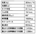
参考として、例えば図6に示す諸条件とされた車両1において、各車輪5a~5dに取り付けられたセンサ送信機2のGセンサ22の検出信号を解析した場合を例に挙げて、具体的にどのように車輪位置検出を行うかについて説明する。
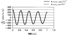
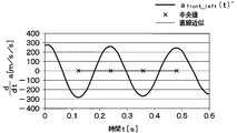
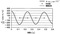
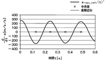
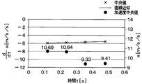
左右前輪5a、5bに取り付けられたセンサ送信機2のGセンサ22の検出信号に基づいて加速度aを測定したところ図8Aの結果が得られた。また、左右後輪5c、5dに取り付けられたセンサ送信機2のGセンサ22の検出信号に基づいて加速度aを測定したところ図8Bの結果が得られた。さらに、左右前輪5a、5bに取り付けられたセンサ送信機2のGセンサ22の検出信号に基づいて加速度aの微分値da/dtを測定したところ図9Aの結果が得られた。また、左右後輪5c、5dに取り付けられたセンサ送信機2のGセンサ22の検出信号に基づいて加速度aの微分値da/dtを測定したところ図9Bの結果が得られた。
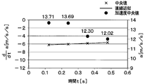
図9A中から右前輪5aの加速度aの微分値da/dtを抽出し、極大値および極小値に基づいて加速度aの微分値da/dtの中央値を求め、それを繋ぐと図10Aのような結果が得られる。この中央値を繋いだ直線が実測1次関数を示す直線となる。また、この実測1次関数を示す直線と、加速度aの中央値を図に示すと、図11Aのような結果となる。
これらの結果より、実測1次関数を示す直線中の2点を用いて、当該2点における加速度aの微分値da/dtの中央値とその中央値のときの時間tを数式23に代入することでC1_front_right、C2_front_rightの連列方程式を得る。また、それを解くことでC1_front_right、C2_front_rightを算出する。そして、実測2次関数が上記した数式22で表されることから、図8A中の加速度aから中央値を1点求め、中央値とその中央値のときの時間tを数式22に代入すると共に、先ほど求めたC1_front_right、C2_front_rightを代入する。これにより、C3_front_rightを算出する。ここでの例では、C1_front_rightが0.6912、C2_front_rightが-6.313、C3_front_rightが12.23となった。
また、数式33-1を用いてBfront_rightを算出すると-4.567となり、θset_front_rightが85°のときにtan(θset_front_right)が11.43になる。このため、数式28-1を用いてDfront_rightを算出すると3.163となった。また、Dfront_right/tan(θset_front_right)は-0.2768となった。
仮に、右前輪5aに備えられたセンサ送信機2がGセンサ22の検出信号に基づいて各値を算出したときには、上記のような値で算出されることになる。このため、算出したBに基づいて加速度a<0と推定でる。さらに、tanθsetが正であり、かつ、方向比例成分D<0となっていて、加速度aと方向比例成分Dの符号が同じであることから、センサ送信機2が取り付けられたのが右車輪5a、5cであると判定することができる。
同様に、左前輪5b、右後輪5cおよび左後輪5dに関しても、加速度aの微分値da/dtを抽出し、加速度aの微分値da/dtの中央値を求め、それを繋ぐと図10B~図10Dのような結果が得られる。各中央値を繋いだ直線が実測1次関数を示す直線となる。また、実測1次関数を示す直線と、加速度aの中央値を図に示すと、図11B~図11Dのような結果となる。
これらの結果に基づいて、右前輪5aと同様に、左前輪5b、右後輪5cおよび左後輪5dに関しても各値を求めると以下のような値となった。
具体的には、左前輪5bについては、C1_front_leftが0.8120、C2_front_leftが-6.393、C3_front_leftが14.76,Bfront_leftが-4.567となった。また、Dfront_leftが2.680、Dfront_left/tan(θset_front_left)は0.2345となった。このため、算出したBに基づいて加速度a<0と推定できる。さらに、tanθsetが正であり、かつ、方向比例成分D>0となっていて、加速度aと方向比例成分Dの符号が異なっていることから、センサ送信機2が取り付けられたのが左車輪5b、5dであると判定することができる。
また、右後輪5cについては、C1_rear_rightが0.6535、C2_rear_rightが-6.085、C3_rear_rightが11.76,Brear_rightが-4.656、Drear_rightが-3.683、Drear_right/tan(θset_rear_right)は-0.3223となった。このため、算出したBに基づいて加速度a<0と推定できる。さらに、tanθsetが正であり、かつ、方向比例成分D<0となっていて、加速度aと方向比例成分Dの符号が同じであることから、センサ送信機2が取り付けられたのが右車輪5a、5cであると判定することができる。
さらに、左後輪5dについては、C1_rear_leftが0.6704、C2_rear_leftが-6.139、C3_rear_leftが14.38,Brear_leftが-4.578、Drear_leftが0.491となった。また、Drear_left/tan(θset_rear_left)は0.04310となった。このため、算出したBに基づいて加速度a<0と推定できる。さらに、tanθsetが正であり、かつ、方向比例成分D>0となっていて、加速度aと方向比例成分Dの符号が異なっていることから、センサ送信機2が取り付けられたのが左車輪5b、5dであると判定することができる。
このようにしてセンサ送信機2が左右いずれの車輪に取り付けられているかが推定されると、その推定結果と推定の際に得られた値等のデータを含むフレームがセンサ送信機2から送信され、これが受信機3で受信される。そして、受信機3において、フレームに格納された推定結果に基づいて、フレームを送信したセンサ送信機2が左右いずれの車輪に取り付けられたものであるかを特定する。さらに、受信機3は、フレームに格納された推定の際に得られた値等に基づいて、センサ送信機2が前後いずれの車輪に取り付けられたものであるかを特定する。これにより、各センサ送信機2が取り付けられているのが車輪5a~5dのいずれであるかを特定することが可能となる。
(他の実施形態)
本開示は、上記した実施形態に準拠して記述されたが、当該実施形態に限定されるものではなく、様々な変形例や均等範囲内の変形をも包含する。加えて、様々な組み合わせや形態、さらには、それらに一要素のみ、それ以上、あるいはそれ以下、を含む他の組み合わせや形態をも、本開示の範疇や思想範囲に入るものである。
本開示は、上記した実施形態に準拠して記述されたが、当該実施形態に限定されるものではなく、様々な変形例や均等範囲内の変形をも包含する。加えて、様々な組み合わせや形態、さらには、それらに一要素のみ、それ以上、あるいはそれ以下、を含む他の組み合わせや形態をも、本開示の範疇や思想範囲に入るものである。
上記実施形態では、受信アンテナ31が1本の共通アンテナとされる形態について説明したが、複数本、例えば各車輪5a~5dそれぞれに対応して4本設けられるような形態であっても構わない。ただし、受信アンテナ31が共通アンテナとされた場合に、特に、センサ送信機2が取り付けられた車輪5a~5dの特定が困難となることから、共有アンテナとされる場合に有効である。
また、上記実施形態では、タイヤ空気圧検出装置に車輪位置検出装置を適用しているため、車輪位置検出の結果を示すデータをタイヤ空気圧に関する情報が格納されるフレームに格納して送信されるようにしている。しかしながら、これはフレーム構成の一例を示したに過ぎず、車輪位置検出の結果を示すデータを格納するフレームとタイヤ空気圧に関する情報を格納するフレームを別々のフレームとしても構わない。ただし、タイヤ空気圧に関する情報が格納されるフレームに各車輪位置検出の結果を示すデータを格納することで、車輪位置検出とタイヤ空気圧検出の両方が行える共通フレームとすることが可能となる。
また、上記実施形態では、センサ送信機2が両前輪5a、5bと両後輪5c、5dのいずれに取り付けられているかの検出手法の一例として実効タイヤ半径に関係する値a/rwの値を用いる場合を例に挙げた。しかしながら、上記実施形態で説明した手法以外の手法を採用しても構わない。例えば、Gセンサ22による加速度の検出結果をフレームに格納し、右車輪5a、5cもしくは左車輪5b、5dに取り付けられたセンサ送信機2のGセンサ22が示す加速度の波形の位相を比較することで、前後いずれの車輪であるかを特定するようにしても良い。また、フレームに実効タイヤ半径に関係する値としてa/rwを格納したが、実効タイヤ半径に関係する値として実効タイヤ半径そのものを格納しても良い。
また、上記実施形態では、車輪位置検出が行われるタイミングでは、ほとんどの場合に車両1が前進中であることに基づいて、加速度aの正負の符号を判定している。これに代えて、他の手法によって加速度aの正負の符号を判定することもできる。例えば、Gセンサ22の検出信号が示す振幅波形の周期が減少傾向にある場合はタイヤ回転周期が短くなっていく加速中、逆に拡大傾向にある場合はタイヤ回転周期が長くなっていく減速中と判定できる。このため、例えば極大値同士もしくは極小値同士の時間間隔から振幅波形の周期を求め、これが減少傾向にあるか拡大傾向にあるかに基づいて、加速度aの符号が正か負かを判定することもできる。
Claims (7)
- 車体(6)に対してタイヤを備えた4つの車輪(5a~5d)が取り付けられた車両(1)に適用される車輪位置検出装置であって、
4つの前記車輪それぞれに備えられ、4つの前記車輪それぞれの径方向に対して周方向に任意の角度ずらした方向を検出方向として加速度を検出する加速度センサ(22)と、前記加速度センサで検出した加速度に基づいて車輪位置検出を行い、該車輪位置検出の結果を示すデータを格納したフレームを作成すると共に送信する第1制御部(23)とを有するセンサ送信機(2、2a~2d)と、
前記車体側に設けられ、受信アンテナ(31)を介して前記センサ送信機から送信されたフレームを受信する受信部(32)と、受信した前記フレームから得られる車輪位置検出の結果を示すデータに基づいて、前記フレームを送信してきた前記センサ送信機が4つの前記車輪うちの右車輪(5a、5c)と左車輪(5b、5d)のいずれに取り付けられたものであるかを特定する第2制御部(33)とを有する受信機(3)とを備え、
前記第1制御部は、
前記加速度センサで検出した加速度に基づいて、前記加速度センサが前記径方向に対して周方向にずらされた前記任意の角度に相当する傾斜角度(θset)を演算し、前記車輪に対して前記傾斜角度で前記加速度センサが取り付けられている場合における加速度の計算値の振幅の中央値を2次関数で近似した計算2次関数と、前記加速度の計算値の微分値の中央値を1次関数で近似した計算1次関数と、前記加速度センサで実際に検出される値の振幅の中央値を2次関数で近似した実測2次関数と、前記加速度センサで実際に検出される値の微分値を1次関数で近似した実測1次関数とに基づいて、該第1制御部が備えられた前記センサ送信機自身が取り付けられたのが前記右車輪と前記左車輪のいずれであるかを推定しており、
前記実測2次関数における2次の項の係数をC1、1次の項をC2、定数項をC3として、前記実測1次関数中の2点における中央値および該中央値となる時間に基づいて前記C1および前記C2を算出すると共に、算出された前記C1および前記C2と前記実測2次関数中の1点における中央値および該中央値となる時間に基づいて前記C3を算出し、
前記車体の加速度をa、車速の初速度をv0、前記傾斜角度をθset、前記車両が加速中であるか減速中であるかを示す加減速指示値をB、前記加速度センサの検知結果から重力加速度成分と遠心加速度成分を取り除いた方向比例成分をDとし、前記v0の符号を正として、前記Bの関係式であるB=C2/C1=v0/aに加えて算出した前記C1および前記C2に基づいて前記aの符号が正か負のいずれであるかを判定すると共に、前記Dの関係式であるD=-(C2/2C1)2+C3/C1に加えて算出した前記C1と前記C2および前記C3に基づいて前記Dを算出し、前記θsetから算出されるtanθsetの符号と前記aと前記Dの符号が同じであるか否かに基づいて、前記センサ送信機自身が取り付けられたのが前記右車輪と前記左車輪のいずれであるかを推定する車輪位置検出装置。 - 前記第1制御部は、
前記tanθsetの符号が正である場合において、前記aと前記Dの符号が同じであれば、前記センサ送信機自身が取り付けられたのが前記右車輪と推定し、前記aと前記Dの符号が異なっていれば、前記センサ送信機自身が取り付けられたのが前記左車輪と推定し、
前記tanθsetの符号が負である場合において、前記aと前記Dの符号が異なっていれば、前記センサ送信機自身が取り付けられたのが前記右車輪と推定し、前記aと前記Dの符号が同じであれば、前記センサ送信機自身が取り付けられたのが前記左車輪と推定する請求項1に記載の車輪位置検出装置。 - 前記第1制御部は、前記加速度センサで検出した加速度に基づいて車速が一定速度であることを検出したときに、前記傾斜角度の演算を行うものであることを特徴とする請求項1または2に記載の車輪位置検出装置。
- 前記第1制御部は、前記計算2次関数における2次の項の係数と前記実測2次関数における2次の項の係数より実効タイヤ半径に関係する値(a/rw)を演算し、該実効タイヤ半径に関係する値のデータを前記フレームに格納すると共に送信し、
前記第2制御部は、前記フレームに格納された前記実効タイヤ半径に関係する値のデータに基づいて、前記センサ送信機のうち前記右車輪に取り付けられたと特定したもの同士の前記実効タイヤ半径を大小比較することで、前記実効タイヤ半径が小さい方のデータを送信してきた前記センサ送信機を右前輪(5a)に取り付けられたものと特定すると共に、前記実効タイヤ半径が大きい方のデータを送信してきた前記センサ送信機を右後輪(5c)に取り付けられたものと特定し、さらに、前記センサ送信機のうち前記左車輪に取り付けられたと特定したもの同士の前記実効タイヤ半径を大小比較することで、前記実効タイヤ半径が小さい方のデータを送信してきた前記センサ送信機を左前輪(5b)に取り付けられたものと特定すると共に、前記実効タイヤ半径が大きい方のデータを送信してきた前記センサ送信機を左後輪(5d)に取り付けられたものと特定することを特徴とする請求項1ないし3のいずれか1つに記載の車輪位置検出装置。 - 前記第1制御部は、前記加速度センサの検出した加速度に基づいて加速中および減速中の前記実効タイヤ半径に関係する値を記憶し、加速中および減速中における前記実効タイヤ半径に関係する値の絶対値を比較し、加速中の値の方が減速中の値よりも小さければ、該第1制御部を備える前記センサ送信機が前輪に取り付けられていると判定し、加速中の値の方が減速中の値よりも小さければ、該第1制御部を備える前記センサ送信機が後輪に取り付けられていると判定することを特徴とする請求項1ないし4のいずれか1つに記載の車輪位置検出装置。
- 請求項1ないし5のいずれか1つに記載の車輪位置検出装置に用いられることを特徴とするセンサ送信機。
- 請求項1ないし5のいずれか1つに記載の車輪位置検出装置を含むタイヤ空気圧検出装置であって、
前記送信機は、4つの前記車輪それぞれに備えられた前記タイヤの空気圧に応じた検出信号を出力するセンシング部(21)を備え、前記第1制御部によって前記センシング部の検出信号を信号処理したタイヤ空気圧に関する情報をフレームに格納して、当該フレームを前記受信機に送信し、
前記受信機は、前記第2制御部にて、該タイヤ空気圧に関する情報より、4つの前記車輪それぞれに備えられた前記タイヤの空気圧を検出することを特徴とするタイヤ空気圧検出装置。
Priority Applications (2)
| Application Number | Priority Date | Filing Date | Title |
|---|---|---|---|
| DE112018000352.3T DE112018000352T5 (de) | 2017-01-11 | 2018-01-11 | Sensor-transmitter, radpositionserfassungsvorrichtung und damitausgerüstetes reifendrucküberwachungssystem |
| US16/442,636 US11084337B2 (en) | 2017-01-11 | 2019-06-17 | Sensor transmitter, wheel positional detection apparatus, and tire pressure monitoring system equipped with the same |
Applications Claiming Priority (2)
| Application Number | Priority Date | Filing Date | Title |
|---|---|---|---|
| JP2017-002723 | 2017-01-11 | ||
| JP2017002723A JP6614164B2 (ja) | 2017-01-11 | 2017-01-11 | センサ送信機、車輪位置検出装置およびそれを備えたタイヤ空気圧検出装置 |
Related Child Applications (1)
| Application Number | Title | Priority Date | Filing Date |
|---|---|---|---|
| US16/442,636 Continuation US11084337B2 (en) | 2017-01-11 | 2019-06-17 | Sensor transmitter, wheel positional detection apparatus, and tire pressure monitoring system equipped with the same |
Publications (1)
| Publication Number | Publication Date |
|---|---|
| WO2018131664A1 true WO2018131664A1 (ja) | 2018-07-19 |
Family
ID=62839749
Family Applications (1)
| Application Number | Title | Priority Date | Filing Date |
|---|---|---|---|
| PCT/JP2018/000533 WO2018131664A1 (ja) | 2017-01-11 | 2018-01-11 | センサ送信機、車輪位置検出装置およびそれを備えたタイヤ空気圧検出装置 |
Country Status (4)
| Country | Link |
|---|---|
| US (1) | US11084337B2 (ja) |
| JP (1) | JP6614164B2 (ja) |
| DE (1) | DE112018000352T5 (ja) |
| WO (1) | WO2018131664A1 (ja) |
Cited By (3)
| Publication number | Priority date | Publication date | Assignee | Title |
|---|---|---|---|---|
| CN110667317A (zh) * | 2019-11-07 | 2020-01-10 | 中国民航大学 | 基于加速度数据的车轮位置定位方法 |
| CN110956240A (zh) * | 2019-12-04 | 2020-04-03 | 东风汽车集团有限公司 | 直接式胎压传感器学习系统,在线学习系统及方法 |
| WO2024047690A1 (ja) * | 2022-08-29 | 2024-03-07 | 太平洋工業株式会社 | 輪位置特定装置、輪位置特定システム、及び輪位置特定方法 |
Families Citing this family (3)
| Publication number | Priority date | Publication date | Assignee | Title |
|---|---|---|---|---|
| JP6613185B2 (ja) * | 2016-03-23 | 2019-11-27 | 株式会社小松製作所 | モータグレーダの制御方法、モータグレーダおよびモータグレーダの作業管理システム |
| DE102016218667A1 (de) * | 2016-09-28 | 2018-03-29 | Robert Bosch Gmbh | Drucksensorvorrichtung sowie Drucksensor |
| US11209455B2 (en) * | 2018-11-30 | 2021-12-28 | Pacific Industrial Co., Ltd. | Acceleration detecting device including a circuitry configuration having a set of calculations during one rotation of a wheel assembly |
Citations (3)
| Publication number | Priority date | Publication date | Assignee | Title |
|---|---|---|---|---|
| JP2013001220A (ja) * | 2011-06-15 | 2013-01-07 | Denso Corp | 車輪位置検出装置およびそれを備えたタイヤ空気圧検出装置 |
| JP2014083884A (ja) * | 2012-10-19 | 2014-05-12 | Tokai Rika Co Ltd | 車輪位置判定装置およびタイヤ空気圧監視システム |
| WO2017047419A1 (ja) * | 2015-09-17 | 2017-03-23 | 株式会社デンソー | センサ送信機、車輪位置検出装置およびそれを備えたタイヤ空気圧検出装置 |
Family Cites Families (8)
| Publication number | Priority date | Publication date | Assignee | Title |
|---|---|---|---|---|
| DE19735686A1 (de) | 1997-08-19 | 1999-02-25 | Doduco Gmbh | Verfahren zum Zuordnen von Kennungen in Signalen von Sendern in einem Reifendrucküberwachungssystem zu den Rädern, an welchen sich die Sender befinden |
| ES2226470T3 (es) | 1998-12-09 | 2005-03-16 | Beru Ag | Procedimiento para asignar indicativos en señales de emisores en un sistema de vigilancia de la presion de los neumaticos a las ruedas en la que se encuentran los emisores. |
| JP4548196B2 (ja) | 2005-04-21 | 2010-09-22 | 株式会社デンソー | 車輪位置検出装置およびそれを備えたタイヤ空気圧検出装置 |
| DE102006031044B4 (de) | 2005-07-06 | 2017-02-02 | Denso Corporation | Rad-Identifizierungsvorrichtung und Reifenfülldruck-Erfassungsvorrichtung mit einer Rad-Identifizierungsfunktion |
| JP2007320423A (ja) * | 2006-05-31 | 2007-12-13 | Nec Electronics Corp | タイヤ位置検出システム |
| US20140379231A1 (en) * | 2013-06-24 | 2014-12-25 | Delphi Technologies, Inc. | System and method for automatic location assignment of wheels equipped with pressure sensors |
| US9823168B2 (en) * | 2014-06-27 | 2017-11-21 | Infineon Technologies Ag | Auto tire localization systems and methods utilizing a TPMS angular position index |
| JP6154532B2 (ja) | 2016-10-12 | 2017-06-28 | フジモリ産業株式会社 | トンネル用ガイド部材 |
-
2017
- 2017-01-11 JP JP2017002723A patent/JP6614164B2/ja not_active Expired - Fee Related
-
2018
- 2018-01-11 WO PCT/JP2018/000533 patent/WO2018131664A1/ja active Application Filing
- 2018-01-11 DE DE112018000352.3T patent/DE112018000352T5/de not_active Ceased
-
2019
- 2019-06-17 US US16/442,636 patent/US11084337B2/en active Active
Patent Citations (3)
| Publication number | Priority date | Publication date | Assignee | Title |
|---|---|---|---|---|
| JP2013001220A (ja) * | 2011-06-15 | 2013-01-07 | Denso Corp | 車輪位置検出装置およびそれを備えたタイヤ空気圧検出装置 |
| JP2014083884A (ja) * | 2012-10-19 | 2014-05-12 | Tokai Rika Co Ltd | 車輪位置判定装置およびタイヤ空気圧監視システム |
| WO2017047419A1 (ja) * | 2015-09-17 | 2017-03-23 | 株式会社デンソー | センサ送信機、車輪位置検出装置およびそれを備えたタイヤ空気圧検出装置 |
Cited By (4)
| Publication number | Priority date | Publication date | Assignee | Title |
|---|---|---|---|---|
| CN110667317A (zh) * | 2019-11-07 | 2020-01-10 | 中国民航大学 | 基于加速度数据的车轮位置定位方法 |
| CN110667317B (zh) * | 2019-11-07 | 2021-06-15 | 中国民航大学 | 基于加速度数据的车轮位置定位方法 |
| CN110956240A (zh) * | 2019-12-04 | 2020-04-03 | 东风汽车集团有限公司 | 直接式胎压传感器学习系统,在线学习系统及方法 |
| WO2024047690A1 (ja) * | 2022-08-29 | 2024-03-07 | 太平洋工業株式会社 | 輪位置特定装置、輪位置特定システム、及び輪位置特定方法 |
Also Published As
| Publication number | Publication date |
|---|---|
| US20190299725A1 (en) | 2019-10-03 |
| JP6614164B2 (ja) | 2019-12-04 |
| US11084337B2 (en) | 2021-08-10 |
| JP2018111386A (ja) | 2018-07-19 |
| DE112018000352T5 (de) | 2019-09-26 |
Similar Documents
| Publication | Publication Date | Title |
|---|---|---|
| WO2018131664A1 (ja) | センサ送信機、車輪位置検出装置およびそれを備えたタイヤ空気圧検出装置 | |
| JP6350467B2 (ja) | センサ送信機、車輪位置検出装置およびそれを備えたタイヤ空気圧検出装置 | |
| JP5447442B2 (ja) | 車輪位置検出装置およびそれを備えたタイヤ空気圧検出装置 | |
| US9459275B2 (en) | Method of sampling acceleration measurements of a motor vehicle wheel | |
| KR101379652B1 (ko) | 타이어 위치 정보 송신 장치 및 방법 | |
| US8576121B2 (en) | Method for lateral localization of the wheels of a vehicle | |
| US10112448B2 (en) | Tire wheel position detection device and tire pressure monitoring system having the same | |
| US10726714B2 (en) | Wheel position detecting device | |
| JP2006027419A (ja) | タイヤ空気圧モニター装置 | |
| KR20130130878A (ko) | 타이어 공기압 모니터 장치 | |
| US9126459B2 (en) | Apparatus and methods for determining the position and/or orientation of a tire mounted unit in a wheel monitoring system | |
| US9694631B2 (en) | Tire position determination system | |
| KR20180070521A (ko) | 타이어 압력 모니터링 시스템 및 타이어 위치 확인 방법 | |
| KR20160130822A (ko) | 타이어 위치 등록 시스템 | |
| JP4289272B2 (ja) | タイヤ空気圧検出装置 | |
| JP2022547378A (ja) | 車輪端部センサとの相関性を使用してタイヤ圧監視センサをロケーション判定する為の位置検知システム及び方法 | |
| KR101521841B1 (ko) | Tpms 좌우측 판별 방법 및 이를 이용한 tpms 좌우측 판별 장치 | |
| JP2016217065A (ja) | 路面粗さの計測装置 | |
| JP2002205517A (ja) | タイヤ空気圧の異常輪判定装置 | |
| KR20110061184A (ko) | 타이어 압력 감지 시스템 송신 모듈의 위치 인식 방법 | |
| TW202229029A (zh) | 多天線胎壓偵測器自動定位裝置 | |
| JP2022027163A (ja) | タイヤ空気圧監視システム | |
| KR101571109B1 (ko) | Tpms 위치 판별 방법 및 이를 이용한 tpms 위치 판별 장치 | |
| KR101856072B1 (ko) | Tpms 센서의 위치 학습 장치 및 방법 | |
| JP6693275B2 (ja) | 移動体検知システム |
Legal Events
| Date | Code | Title | Description |
|---|---|---|---|
| 121 | Ep: the epo has been informed by wipo that ep was designated in this application |
Ref document number: 18739065 Country of ref document: EP Kind code of ref document: A1 |
|
| 122 | Ep: pct application non-entry in european phase |
Ref document number: 18739065 Country of ref document: EP Kind code of ref document: A1 |