WO2018131371A1 - 触覚呈示装置 - Google Patents
触覚呈示装置 Download PDFInfo
- Publication number
- WO2018131371A1 WO2018131371A1 PCT/JP2017/044708 JP2017044708W WO2018131371A1 WO 2018131371 A1 WO2018131371 A1 WO 2018131371A1 JP 2017044708 W JP2017044708 W JP 2017044708W WO 2018131371 A1 WO2018131371 A1 WO 2018131371A1
- Authority
- WO
- WIPO (PCT)
- Prior art keywords
- heat transfer
- transfer member
- temperature sensor
- terminal portions
- presentation device
- Prior art date
- Legal status (The legal status is an assumption and is not a legal conclusion. Google has not performed a legal analysis and makes no representation as to the accuracy of the status listed.)
- Ceased
Links
Images





Classifications
-
- H—ELECTRICITY
- H10—SEMICONDUCTOR DEVICES; ELECTRIC SOLID-STATE DEVICES NOT OTHERWISE PROVIDED FOR
- H10N—ELECTRIC SOLID-STATE DEVICES NOT OTHERWISE PROVIDED FOR
- H10N10/00—Thermoelectric devices comprising a junction of dissimilar materials, i.e. devices exhibiting Seebeck or Peltier effects
- H10N10/10—Thermoelectric devices comprising a junction of dissimilar materials, i.e. devices exhibiting Seebeck or Peltier effects operating with only the Peltier or Seebeck effects
- H10N10/17—Thermoelectric devices comprising a junction of dissimilar materials, i.e. devices exhibiting Seebeck or Peltier effects operating with only the Peltier or Seebeck effects characterised by the structure or configuration of the cell or thermocouple forming the device
-
- G—PHYSICS
- G06—COMPUTING OR CALCULATING; COUNTING
- G06F—ELECTRIC DIGITAL DATA PROCESSING
- G06F3/00—Input arrangements for transferring data to be processed into a form capable of being handled by the computer; Output arrangements for transferring data from processing unit to output unit, e.g. interface arrangements
- G06F3/01—Input arrangements or combined input and output arrangements for interaction between user and computer
-
- G—PHYSICS
- G06—COMPUTING OR CALCULATING; COUNTING
- G06F—ELECTRIC DIGITAL DATA PROCESSING
- G06F3/00—Input arrangements for transferring data to be processed into a form capable of being handled by the computer; Output arrangements for transferring data from processing unit to output unit, e.g. interface arrangements
- G06F3/01—Input arrangements or combined input and output arrangements for interaction between user and computer
- G06F3/03—Arrangements for converting the position or the displacement of a member into a coded form
- G06F3/041—Digitisers, e.g. for touch screens or touch pads, characterised by the transducing means
-
- G—PHYSICS
- G08—SIGNALLING
- G08B—SIGNALLING SYSTEMS, e.g. PERSONAL CALLING SYSTEMS; ORDER TELEGRAPHS; ALARM SYSTEMS
- G08B6/00—Tactile signalling systems, e.g. tactile personal calling systems
-
- H—ELECTRICITY
- H10—SEMICONDUCTOR DEVICES; ELECTRIC SOLID-STATE DEVICES NOT OTHERWISE PROVIDED FOR
- H10N—ELECTRIC SOLID-STATE DEVICES NOT OTHERWISE PROVIDED FOR
- H10N10/00—Thermoelectric devices comprising a junction of dissimilar materials, i.e. devices exhibiting Seebeck or Peltier effects
- H10N10/10—Thermoelectric devices comprising a junction of dissimilar materials, i.e. devices exhibiting Seebeck or Peltier effects operating with only the Peltier or Seebeck effects
- H10N10/13—Thermoelectric devices comprising a junction of dissimilar materials, i.e. devices exhibiting Seebeck or Peltier effects operating with only the Peltier or Seebeck effects characterised by the heat-exchanging means at the junction
-
- H—ELECTRICITY
- H10—SEMICONDUCTOR DEVICES; ELECTRIC SOLID-STATE DEVICES NOT OTHERWISE PROVIDED FOR
- H10N—ELECTRIC SOLID-STATE DEVICES NOT OTHERWISE PROVIDED FOR
- H10N10/00—Thermoelectric devices comprising a junction of dissimilar materials, i.e. devices exhibiting Seebeck or Peltier effects
- H10N10/80—Constructional details
- H10N10/81—Structural details of the junction
- H10N10/817—Structural details of the junction the junction being non-separable, e.g. being cemented, sintered or soldered
Definitions
- the present invention relates to a tactile presentation device that presents a tactile sensation such as a warm sensation or a cold sensation, and more particularly to a tactile sensation presentation device using a thermoelectric element.
- a temperature detection sensor is provided on the surface of a Peltier element with which a finger or the like comes into contact.
- the sensor is likely to come off during repeated use, or wear and the like are likely to occur, which has the disadvantage of low durability. is there.
- the unevenness by the sensor gives a sense of discomfort to the touch.
- the present invention has been made in view of such circumstances, and an object of the present invention is to provide a tactile sensation presentation apparatus capable of suppressing a decrease in durability and presenting a good tactile sensation without discomfort.
- a tactile sensation presentation apparatus includes a contacted surface that can be contacted by a tactile presentation target, a thermoelectric conversion unit that generates cold or heat transmitted to the contacted surface, and a temperature sensor that detects a temperature of the contacted surface.
- the thermoelectric conversion unit includes at least one thermoelectric member that generates a temperature difference between the first heat transfer member and the second heat transfer member based on the first and second heat transfer members and the supplied power.
- the contacted surface is formed on the surface of the first heat transfer member, or is formed on the surface of another heat transfer member that contacts the surface of the first heat transfer member.
- the temperature sensor is located outside a region where the contacted surface is formed on the surface of the first heat transfer member, or outside a region contacting the other heat transfer member on the surface of the first heat transfer member. Be placed.
- a tactile sense presentation target such as a finger does not directly touch the temperature sensor.
- durability improves compared with the case where the tactile sense presentation object touches the said temperature sensor directly.
- the temperature sensor is arranged outside the region in contact with the other heat transfer member on the surface of the first heat transfer member. Adhesion with the heat member is improved, and the cold or warm heat of the thermoelectric element is easily transmitted to the contacted surface.
- the first heat transfer member may have a plate shape.
- the thermoelectric element may abut on one surface of the first heat transfer member.
- the contacted surface is formed on the other surface of the first heat transfer member, or formed on the surface of the other heat transfer member in contact with the other surface of the first heat transfer member.
- the temperature sensor may be disposed on the one surface of the first heat transfer member.
- the temperature sensor is disposed on the one surface of the first heat transfer member where the contacted surface is not formed, a tactile sense presentation target such as a finger does not directly touch the temperature sensor. . Thereby, a sense of incongruity of touch does not occur and durability is improved.
- the other heat transfer member abuts on the other surface of the first heat transfer member having a plate shape, the first heat transfer member and the other heat transfer member are in contact with each other.
- the member is easily brought into contact with a large area, and the cold or warm heat of the thermoelectric element is easily transmitted to the contacted surface.
- the said tactile sense presentation apparatus may have a heat sink member which suppresses the temperature change of the said 2nd heat-transfer member.
- the second heat transfer member may have a plate shape.
- the first heat transfer member and the second heat transfer member may be arranged to face each other.
- the thermoelectric element may contact one surface of the second heat transfer member.
- the heat sink member may abut on the other surface of the second heat transfer member.
- Two detection terminal portions for connecting two detection wires for transmitting a detection signal of the temperature sensor may be formed on the one surface of the second heat transfer member.
- the heat sink member contacts the other surface of the second heat transfer member, while the two detection terminal portions are formed on the one surface of the second heat transfer member. Accordingly, the second heat transfer member and the heat sink member can be brought into contact with each other over a wide area without being interfered by the two detection terminal portions.
- the temperature sensor may be positioned between the two detection terminal portions in a plan view as viewed from a direction perpendicular to each surface of the first heat transfer member and the second heat transfer member.
- thermoelectric element since the area occupied by the two detection terminal portions and the temperature sensor in the plan view is small, the area for arranging the thermoelectric element is relatively large.
- the first heat transfer member and the second heat transfer member may have a rectangular shape in the plan view.
- the two detection terminal portions may be arranged at an end portion of the second heat transfer member along one side of the rectangular shape.
- thermoelectric element is arranged in the plan view.
- the area for this is relatively large.
- two driving terminal portions for connecting two driving wirings for supplying electric power to the thermoelectric element may be formed on the one surface of the second heat transfer member.
- the two drive terminal portions may be aligned with the two end portions of the second heat transfer member along the one side of the rectangular shape together with the two detection terminal portions.
- the heat sink member abuts on the other surface of the second heat transfer member, while the two drive terminal portions are formed on the one surface of the second heat transfer member. Accordingly, the second heat transfer member and the heat sink member can be brought into contact with each other over a wide area without being interfered by the two drive terminal portions.
- the two detection terminal portions and the two drive terminal portions are aligned with the end of the second heat transfer member along one side of the rectangular shape. A region for arranging the thermoelectric element becomes relatively large.
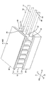
- FIG. 1 is a perspective view showing an example of a tactile sensation presentation apparatus
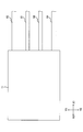
- FIG. 2 is a front view showing an example of the haptic presentation apparatus
- FIG. 3 is a plan view showing an example of the tactile presentation apparatus.
- FIG. 4 is a diagram in which the first heat transfer member 11 is not shown in the plan view of FIG. 3.
- X three directions orthogonal to each other are denoted as “X”, “Y”, and “Z”.
- the opposite directions included in the X direction are denoted as “X1” and “X2”
- the opposite directions included in the Y direction are denoted as “Y1” and “Y2”
- the opposite directions included in the Z direction are denoted as “Z1” and “Z2”.
- the front view of FIG. 2 is the figure which looked at the Y1 direction from the Y2 side
- the top view of FIG. 3 is the figure which looked at the Z2 direction from the Z1 side.
- viewing from the Z direction may be referred to as “plan view”.
- the tactile sensation presentation apparatus has a contacted surface A that can be touched by a tactile sensation presentation target such as a finger.
- the contacted surface A is a plane perpendicular to the Z direction and is formed on the surface of a thermoelectric conversion unit 10 described later.
- the tactile sense presentation device includes a thermoelectric converter 10, a temperature sensor 20, and a heat sink member 30.
- thermoelectric converter 10 is a device that generates cold or warm heat transmitted to the contacted surface A.
- the thermoelectric conversion unit 10 includes a first heat transfer member 11, a second heat transfer member 12, and a plurality of thermoelectric elements 13.
- the first heat transfer member 11 and the second heat transfer member 12 each have a plate shape and are disposed to face each other. Each surface of the first heat transfer member 11 and the second heat transfer member 12 is substantially perpendicular to the Z direction. That is, the Z1 side surface 111 and the Z1 side surface 112 of the first heat transfer member 11 and the Z1 side surface 121 and the Z2 side surface 122 of the second heat transfer member 12 are both in the Z direction. It is vertical.
- the contacted surface A is formed on the surface 112 on the Z1 side of the first heat transfer member 11.
- the first heat transfer member 11 and the second heat transfer member 12 have a rectangular shape. As shown in FIG. 3, the rectangular shapes of the first heat transfer member 11 and the second heat transfer member 12 are substantially congruent, and are substantially overlapped in plan view.
- the first heat transfer member 11 and the second heat transfer member 12 are made of an insulating material such as ceramic or resin.
- the thermoelectric element 13 is a Peltier element, for example, and generates a temperature difference between the first heat transfer member 11 and the second heat transfer member 12 based on electric power supplied from a thermoelectric element drive circuit 80 described later.
- the thermoelectric element 13 has a prismatic shape extending in the Z direction.
- the end surface on the Z1 side of the thermoelectric element 13 abuts on the Z2 side surface 111 of the first heat transfer member 11, and the end surface on the Z2 side of the thermoelectric element 13 abuts on the Z1 side surface 121 of the second heat transfer member 12.
- the plurality of thermoelectric elements 13 are arranged in a matrix in a plan view. In the example of FIG. 4, the number of columns arranged in the X direction and the number of rows arranged in the Y direction are 6, respectively.
- the temperature sensor 20 is a sensor that detects the temperature of the contacted surface A, and includes, for example, a thermistor.
- the temperature sensor 20 is disposed outside the region where the contacted surface A is formed on the surface of the first heat transfer member 11.
- the temperature sensor 20 is disposed on the surface 111 on the Z2 side of the first heat transfer member 11 as shown in FIGS.
- the heat sink member 30 is disposed in contact with the Z2 side surface 122 of the second heat transfer member 12 and suppresses the temperature change of the second heat transfer member 12.
- the heat sink member 30 may be, for example, a component having a metal housing having high thermal conductivity, and specifically, a component including a vibration generator such as a solenoid or a motor.
- the tactile sense presentation device has two detection terminal portions 51 and 52 as shown in FIGS.
- the detection terminal portions 51 and 52 are connected to two detection wirings 61 and 62 that transmit a detection signal of the temperature sensor 20.
- a current supplied to a sensor element such as a thermistor included in the temperature sensor 20 flows through the two detection wires 61 and 62.
- the detection terminal portions 51 and 52 are, for example, land electrodes, and are connected to the detection wirings 61 and 62 by soldering.
- the two detection terminal portions 51 and 52 are formed on the surface 121 on the Z1 side of the second heat transfer member 12.
- the detection terminal portions 51 and 52 are provided at the end of the second heat transfer member 12 on the X1 side along the X1 side in the rectangular shape of the surface 121 of the second heat transfer member 12 (that is, along the Y direction).
- the temperature sensor 20 is positioned between the detection terminal portions 51 and 52 in a plan view.
- the temperature sensor 20 is located in the approximate center of the Y direction of the 2nd heat-transfer member 12 in planar view.
- the tactile sense presentation device has two drive terminal portions 53 and 54 as shown in FIGS.
- the drive terminal portions 53 and 54 are connected to two drive wires 63 and 64 that supply power to the thermoelectric element 13.
- the plurality of thermoelectric elements 13 of the thermoelectric conversion unit 10 are connected in series by wires formed on the first heat transfer member 11 and the second heat transfer member 12.
- the current supplied to the plurality of thermoelectric elements 13 connected in series flows through the two drive wirings 63 and 64.
- the drive terminal portions 53 and 54 are, for example, land electrodes, and are connected to the drive wirings 63 and 64 by soldering.
- the two drive terminal portions 53 and 54 are formed on the Z1 side surface 121 of the second heat transfer member 12.
- the drive terminal portions 53 and 54, together with the detection terminal portions 51 and 52, are arranged along the X1 side of the rectangular shape of the surface 121 of the second heat transfer member 12 (that is, along the Y direction). It is lined up at the end of the member 12 on the X1 side.
- the two drive terminal portions 53 and 54 are arranged at positions sandwiching the two detection terminal portions 51 and 52 in the Y direction.
- FIG. 5 is a diagram illustrating an example of a configuration of a control system in the tactile sensation presentation apparatus according to the first embodiment.
- the tactile presentation device includes a control unit 70 that controls the overall operation of the tactile presentation device, and a thermoelectric element that supplies power to each thermoelectric element 13 according to the control of the control unit 70.
- the drive circuit 80 includes an interface unit 90 that exchanges signals such as control commands and temperature detection values between a control unit 70 and a device (not shown) such as a host controller.
- the control unit 70 performs a process of controlling the temperature of the contacted surface A in accordance with, for example, a control command input via the interface unit 90. That is, the controller 70 supplies power (for example, thermoelectric power) supplied from the thermoelectric element drive circuit 80 to the thermoelectric element 13 so that the temperature of the contacted surface A detected by the temperature sensor 20 approaches the temperature specified by the control command. The magnitude of the current flowing through the element 13 is controlled. In addition, the control unit 70 determines a range in which the temperature of the contacted surface A is predetermined in a steady state (a state where a finger or the like is not in contact with the contacted surface A) before and after the period in which the tactile sensation is presented. The process of controlling the temperature of the contacted surface A is performed so as to be maintained inside. Thereby, the response speed of the tactile sensation is increased.
- power for example, thermoelectric power supplied from the thermoelectric element drive circuit 80 to the thermoelectric element 13 so that the temperature of the contacted surface A detected by the temperature sensor 20 approaches the temperature specified by the control command.
- the temperature sensor 20 is arranged outside the region where the contacted surface A is formed on the surface of the heat transfer member 11, so that a tactile presentation target such as a finger is present. Do not touch the temperature sensor 20 directly. Thereby, durability can be improved compared with the conventional apparatus with which a finger
- the temperature sensor 20 is arranged on the surface 111 on the Z2 side of the first heat transfer member 11 where the contacted surface A is not formed.
- the object to be presented does not touch the temperature sensor 20 directly.
- durability can be improved compared with the conventional apparatus, and generation
- the temperature sensor 20 is arrange
- the heat sink member 30 abuts on the Z2 side surface 122 of the second heat transfer member 12, while the two detection terminal portions 51 and 52 are in the second transfer state. It is formed on the surface 121 on the Z1 side of the thermal member 12. Accordingly, the second heat transfer member 12 and the heat sink member 30 can be brought into contact with each other over a wide area without being interfered by the two detection terminal portions 51 and 52. The temperature change can be effectively suppressed. Since the temperature change of the second heat transfer member 12 is reduced, the temperature setting accuracy of the contacted surface A is improved, and a higher quality tactile sensation can be presented.
- the two detection terminal portions 51 in a plan view as viewed from the Z direction perpendicular to each surface of the first heat transfer member 11 and the second heat transfer member 12.
- the temperature sensor 20 is located in the middle of 52.
- the area occupied by the two detection terminal portions 51 and 52 and the temperature sensor 20 in the plan view is reduced, and the area for arranging the thermoelectric element 13 is relatively increased. Therefore, the arrangement density of the thermoelectric elements 13 can be increased, and the size of the apparatus can be reduced.
- two end portions of the surface 121 of the second heat transfer member 12 are provided along one side of the rectangular shape of the surface 121 of the second heat transfer member 12.
- the detection terminal portions 51 and 52 are arranged side by side. That is, the two detection terminal portions 51 and 52 are arranged together at the end of the surface 121. Thereby, since the area
- the heat sink member 30 abuts on the Z2 side surface 122 of the second heat transfer member 12, while the two drive terminal portions 53 and 54 are in the second transfer. It is formed on the surface 121 on the Z1 side of the thermal member 12.
- the second heat transfer member 12 and the heat sink member 30 can be brought into contact with each other over a wide area without being interfered by the two drive terminal portions 53 and 54, and the temperature of the second heat transfer member 12 can be increased. Changes can be effectively suppressed.
- the two drive terminal portions 53 and 54 together with the two detection terminal portions 51 and 52 are in the rectangular shape of the surface 121 of the second heat transfer member 12. Along one side, the second heat transfer member 12 is aligned with the end of the surface 121. That is, four terminal portions (51 to 54) are arranged together at the end of the surface 121.
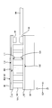
- FIGS. 6 to 8 are diagrams showing an example of a tactile sense presentation device according to the second embodiment. 6 is a perspective view, FIG. 7 is a front view, and FIG. 8 is a plan view.
- the tactile presentation device according to the second embodiment is obtained by adding the third heat transfer member 40 to the tactile presentation device according to the first embodiment which has already been described, and other configurations according to the first embodiment. It is almost the same as the tactile sense presentation device.
- the third heat transfer member 40 is an example of another heat transfer member in the present invention. The following description will focus on differences from the tactile sense presentation device shown in FIGS.
- the third heat transfer member 40 is in contact with the Z1 side surface 112 of the first heat transfer member 11 and has a plate shape as shown in FIGS.
- a contacted surface A is formed on the Z1 side surface 402 of the third heat transfer member 40.
- a surface 401 on the Z2 side of the third heat transfer member 40 abuts on a surface 112 on the Z1 side of the first heat transfer member 11.
- the third heat transfer member 40 is, for example, a part such as a flexible substrate, a protective sheet member, a case or a housing that houses a tactile presentation device. Cold heat and warm heat from the first heat transfer member 11 are indirectly transmitted to the contacted surface A via the third heat transfer member 40.
- the temperature sensor 20 is disposed outside the region in contact with the third heat transfer member 40 on the surface of the first heat transfer member 11. Compared with the case where the temperature sensor 20 is disposed inside, the adhesion between the first heat transfer member 11 and the third heat transfer member 40 is improved, and the cold or warm temperature of the thermoelectric element 13 passes through the third heat transfer member 40. Thus, it is easy to be transmitted to the contacted surface A. Therefore, the temperature setting accuracy of the contacted surface A is improved, and a higher quality tactile sensation can be presented.
- the temperature sensor 20 is disposed on the surface 111 on the Z2 side of the first heat transfer member 11, but the present invention is not limited to this example.
- the first transfer is performed.
- the temperature sensor 20 may be disposed in a region 112 on the Z1 side of the thermal member 11 and outside the contacted surface A.
- the tactile presentation target such as a finger can be prevented from directly touching the temperature sensor 20, so that the durability can be enhanced as compared with the conventional device, and the occurrence of a sense of incongruity of the tactile sensation can be prevented. Good tactile sensation can be presented.
- the temperature sensor 20 is arranged at the end of the Z2 side surface 111 of the first heat transfer member 11, but in another embodiment of the present invention, the location away from the end of the surface 111.
- a temperature sensor may be arranged (for example, at the center).
Landscapes
- Engineering & Computer Science (AREA)
- General Engineering & Computer Science (AREA)
- Theoretical Computer Science (AREA)
- Physics & Mathematics (AREA)
- General Physics & Mathematics (AREA)
- Human Computer Interaction (AREA)
- User Interface Of Digital Computer (AREA)
- Cooling Or The Like Of Electrical Apparatus (AREA)
- Manipulator (AREA)
- Force Measurement Appropriate To Specific Purposes (AREA)
Abstract
触覚呈示装置は、触覚呈示対象によって接触され得る被接触面Aと、被接触面Aに伝わる冷熱又は温熱を発生する熱電変換部10と、被接触面Aの温度を検出する温度センサ20とを有する。熱電変換部10は、第1伝熱部材11及び第2伝熱部材12と、供給される電力に基づいて第1伝熱部材11と第2伝熱部材12との温度差を発生する複数の熱電素子13とを含む。被接触面Aは、第1伝熱部材11の表面に形成される。温度センサ20は、第1伝熱部材11の表面において被接触面Aが形成される領域の外側に配置される。
Description
本発明は、温覚や冷覚などの触覚を呈示する触覚呈示装置に係り、特に熱電素子を用いた触覚呈示装置に関するものである。
近年、VR(virtual reality)を実現する機器の普及に伴って、人の触覚を電気的・機械的に再現する技術が注目されている。下記の特許文献1には、ペルチェ素子を用いて任意の温覚を再現する温覚呈示装置が記載されている。
ペルチェ素子を用いて任意の温覚を再現するためには、ペルチェ素子の温度を検出して制御する必要がある。特許文献1の図7、図8に記載される装置では、指などが接触されるペルチェ素子の表面に温度検出用のセンサが設けられている。しかしながら、指が接触される部分にセンサが貼り付けられていると、繰り返し使用しているうちにセンサが外れ易くなったり、摩耗などを生じ易くなったりするため、耐久性が低いという不利益がある。また、センサによる凹凸が触覚の違和感を与えてしまうという不利益もある。
本発明はかかる事情に鑑みてなされたものであり、その目的は、耐久性の低下を抑制し、違和感のない良好な触覚を呈示できる触覚呈示装置を提供することにある。
本発明に係る触覚呈示装置は、触覚呈示対象によって接触され得る被接触面と、前記被接触面に伝わる冷熱又は温熱を発生する熱電変換部と、前記被接触面の温度を検出する温度センサとを有する。前記熱電変換部は、第1伝熱部材及び第2伝熱部材と、供給される電力に基づいて前記第1伝熱部材と前記第2伝熱部材との温度差を発生する少なくとも1つの熱電素子とを含む。前記被接触面は、前記第1伝熱部材の表面に形成されるか、若しくは、前記第1伝熱部材の表面に当接する別の伝熱部材の表面に形成される。前記温度センサは、前記第1伝熱部材の表面において前記被接触面が形成される領域の外側、若しくは、前記第1伝熱部材の表面において前記別の伝熱部材に当接する領域の外側に配置される。
この構成によれば、前記第1伝熱部材の表面において前記被接触面が形成される領域の外側に前記温度センサが配置されるため、指などの触覚呈示対象が前記温度センサに直接触れない。これにより、触覚呈示対象が前記温度センサに直接触れる場合に比べて耐久性が向上する。また、触覚呈示対象が前記温度センサに直接触れることによる触覚の違和感が生じない。
また、この構成によれば、前記第1伝熱部材の表面において前記別の伝熱部材に当接する領域の外側に前記温度センサが配置されるため、前記第1伝熱部材と前記別の伝熱部材との密着性が良くなり、前記熱電素子の冷熱又は温熱が前記被接触面へ伝わり易くなる。
好適に、前記第1伝熱部材は、板状の形状を持ってよい。前記熱電素子は、前記第1伝熱部材の一方の面に当接してよい。前記被接触面は、前記第1伝熱部材の他方の面に形成されるか、若しくは、前記第1伝熱部材の前記他方の面に当接する前記別の伝熱部材の表面に形成されてよい。前記温度センサは、前記第1伝熱部材の前記一方の面に配置されてよい。
この構成によれば、前記被接触面が形成されていない前記第1伝熱部材の前記一方の面に前記温度センサが配置されるため、指などの触覚呈示対象が前記温度センサに直接触れない。これにより、触覚の違和感が生じなくなり、耐久性が向上する。
また、この構成によれば、板状の形状を持った前記第1伝熱部材の前記他方の面に前記別の伝熱部材が当接するため、前記第1伝熱部材と前記別の伝熱部材とを広い面積で当接させ易くなり、前記熱電素子の冷熱又は温熱が前記被接触面へ伝わり易くなる。
好適に、上記触覚呈示装置は、前記第2伝熱部材の温度変化を抑制するヒートシンク部材を有してよい。前記第2伝熱部材は、板状の形状を持ってよい。前記第1伝熱部材と前記第2伝熱部材とが対向して配置されてよい。前記熱電素子は、前記第2伝熱部材の一方の面に当接してよい。前記ヒートシンク部材は、前記第2伝熱部材の他方の面に当接してよい。前記温度センサの検出信号を伝送する2つの検出用配線を接続するための2つの検出用端子部が、前記第2伝熱部材の前記一方の面に形成されてよい。
この構成によれば、前記ヒートシンク部材が前記第2伝熱部材の他方の面に当接する一方で、前記2つの検出用端子部が前記第2伝熱部材の前記一方の面に形成される。これにより、前記2つの検出用端子部によって干渉されることなく、前記第2伝熱部材と前記ヒートシンク部材とを広い面積で当接させることが可能となる。
好適に、前記第1伝熱部材及び前記第2伝熱部材の各面に垂直な方向から見た平面視において、前記2つの検出用端子部の中間に前記温度センサが位置してよい。
この構成によれば、前記平面視において前記2つの検出用端子部と前記温度センサとにより占められた領域が小さくなるため、前記熱電素子を配置させるための領域が相対的に大きくなる。
好適に、前記第1伝熱部材及び前記第2伝熱部材は、前記平面視において矩形の形状を持ってよい。前記2つの検出用端子部は、前記矩形の形状における1つの辺に沿って前記第2伝熱部材の端部に並んでよい。
この構成によれば、前記矩形の形状における1つの辺に沿って前記第2伝熱部材の端部に前記2つの検出用端子部が並んでいるため、前記平面視において前記熱電素子を配置させるための領域が相対的に大きくなる。
好適に、前記熱電素子に電力を供給する2つの駆動用配線を接続するための2つの駆動用端子部が、前記第2伝熱部材の前記一方の面に形成されてよい。前記2つの駆動用端子部は、前記2つの検出用端子部とともに、前記矩形の形状における前記1つの辺に沿って前記第2伝熱部材の前記端部に並んでいてよい。
この構成によれば、前記ヒートシンク部材が前記第2伝熱部材の他方の面に当接する一方で、前記2つの駆動用端子部が前記第2伝熱部材の前記一方の面に形成される。これにより、前記2つの駆動用端子部によって干渉されることなく、前記第2伝熱部材と前記ヒートシンク部材とを広い面積で当接させることが可能となる。また、前記2つの検出用端子部と前記2つの駆動用端子部とが、前記矩形の形状における1つの辺に沿って前記第2伝熱部材の端部に並んでいるため、前記平面視において前記熱電素子を配置させるための領域が相対的に大きくなる。
本発明によれば、耐久性の低下を抑制し、違和感のない良好な触覚を呈示できる。
<第1の実施形態>
以下、本発明の第1の実施形態に係る触覚呈示装置について図面を参照しながら説明する。図1は触覚呈示装置の一例を示す斜視図であり、図2は触覚呈示装置の一例を示す正面図であり、図3は触覚呈示装置の一例を示す平面図である。図4は、図3の平面図において第1伝熱部材11の図示を省略した図である。
以下、本発明の第1の実施形態に係る触覚呈示装置について図面を参照しながら説明する。図1は触覚呈示装置の一例を示す斜視図であり、図2は触覚呈示装置の一例を示す正面図であり、図3は触覚呈示装置の一例を示す平面図である。図4は、図3の平面図において第1伝熱部材11の図示を省略した図である。
本明細書では、互いに直交する3つの方向を「X」、「Y」、「Z」と記す。また、X方向に含まれる互いに逆の方向を「X1」及び「X2」と記し、Y方向に含まれる互いに逆の方向を「Y1」及び「Y2」と記し、Z方向に含まれる互いに逆の方向を「Z1」及び「Z2」と記す。図2の正面図はY2側からY1方向を見た図であり、図3の平面図はZ1側からZ2方向を見た図である。以下の説明では、Z方向から見ることを「平面視」と記す場合がある。
本実施形態に係る触覚呈示装置は、指などの触覚呈示対象が接触し得る被接触面Aを有する。図1の例において、被接触面AはZ方向に垂直な平面であり、後述する熱電変換部10の表面に形成される。
図1及び図2に示すように、本実施形態に係る触覚呈示装置は、熱電変換部10と、温度センサ20と、ヒートシンク部材30を有する。
熱電変換部10は、被接触面Aに伝わる冷熱又は温熱を発生する装置である。図1及び図2の例において、熱電変換部10は、第1伝熱部材11及び第2伝熱部材12と複数の熱電素子13を含む。
第1伝熱部材11及び第2伝熱部材12は、それぞれ板状の形状を持ち、互いに対向して配置される。第1伝熱部材11及び第2伝熱部材12の各面は、Z方向に対して略垂直である。すなわち、第1伝熱部材11のZ2側の面111及びZ1側の面112と、第2伝熱部材12のZ1側の面121及びZ2側の面122とが、何れもZ方向に対して垂直である。被接触面Aは、第1伝熱部材11のZ1側の面112に形成される。平面視において、第1伝熱部材11及び第2伝熱部材12は矩形の形状を持つ。図3に示すように、第1伝熱部材11及び第2伝熱部材12の当該矩形形状は略合同であり、平面視において略全体が重なっている。第1伝熱部材11及び第2伝熱部材12は、例えばセラミックスや樹脂などの絶縁性の材料からなる。
熱電素子13は、例えばペルチェ素子であり、後述する熱電素子駆動回路80から供給される電力に基づいて第1伝熱部材11と第2伝熱部材12との間の温度差を発生する。
図1に示すように、熱電素子13はZ方向に延びた角柱状の形状を持つ。熱電素子13のZ1側の端面が第1伝熱部材11のZ2側の面111に当接し、熱電素子13のZ2側の端面が第2伝熱部材12のZ1側の面121に当接する。図4に示すように、複数の熱電素子13が平面視において行列状に配置される。図4の例では、X方向に並んだ列の数とY方向に並んだ行の数がそれぞれ6である。
図1に示すように、熱電素子13はZ方向に延びた角柱状の形状を持つ。熱電素子13のZ1側の端面が第1伝熱部材11のZ2側の面111に当接し、熱電素子13のZ2側の端面が第2伝熱部材12のZ1側の面121に当接する。図4に示すように、複数の熱電素子13が平面視において行列状に配置される。図4の例では、X方向に並んだ列の数とY方向に並んだ行の数がそれぞれ6である。
温度センサ20は、被接触面Aの温度を検出するセンサであり、例えばサーミスタを含む。温度センサ20は、第1伝熱部材11の表面において被接触面Aが形成される領域の外側に配置される。例えば温度センサ20は、図1及び図2に示すように、第1伝熱部材11のZ2側の面111に配置される。
ヒートシンク部材30は、第2伝熱部材12のZ2側の面122に当接して配置されており、第2伝熱部材12の温度変化を抑制する。ヒートシンク部材30は、例えば熱伝導性の高い金属の筐体を有した部品でもよく、具体的には、ソレノイドやモータ等の振動発生器が含まれた部品でもよい。
本実施形態に係る触覚呈示装置は、図1及び図4に示すように、2つの検出用端子部51及び52を有する。検出用端子部51及び52は、温度センサ20の検出信号を伝送する2つの検出用配線61及び62に接続される。温度センサ20に含まれるサーミスタ等のセンサ素子へ供給される電流は、2つの検出用配線61及び62を通じて流れる。検出用端子部51及び52は、例えばランド電極であり、半田付けによって検出用配線61及び62に接続される。
2つの検出用端子部51及び52は、第2伝熱部材12のZ1側の面121に形成される。検出用端子部51及び52は、第2伝熱部材12の面121の矩形形状におけるX1側の辺に沿って(すなわちY方向に沿って)第2伝熱部材12のX1側の端部に並んでいる。図4に示すように、温度センサ20は、平面視において、検出用端子部51及び52の中間に位置する。また温度センサ20は、平面視において、第2伝熱部材12のY方向の略中央に位置する。
本実施形態に係る触覚呈示装置は、図1及び図4に示すように、2つの駆動用端子部53及び54を有する。駆動用端子部53及び54は、熱電素子13に電力を供給する2つの駆動用配線63及び64に接続される。熱電変換部10の複数の熱電素子13は、第1伝熱部材11や第2伝熱部材12に形成された配線によって直列に接続される。直列接続された複数の熱電素子13へ供給される電流は、2つの駆動用配線63及び64を通じて流れる。駆動用端子部53及び54は、例えばランド電極であり、半田付けによって駆動用配線63及び64に接続される。
2つの駆動用端子部53及び54は、第2伝熱部材12のZ1側の面121に形成される。駆動用端子部53及び54は、検出用端子部51及び52とともに、第2伝熱部材12の面121の矩形形状におけるX1側の辺に沿って(すなわちY方向に沿って)第2伝熱部材12のX1側の端部に並んでいる。図4に示すように、2つの駆動用端子部53及び54は、Y方向において2つの検出用端子部51及び52を挟んだ位置に配置される。
図5は、第1の実施形態に係る触覚呈示装置における制御系の構成の一例を示す図である。図5に示すように、本実施形態に係る触覚呈示装置は、触覚呈示装置の全体的な動作を制御する制御部70と、制御部70の制御に従って各熱電素子13に電力を供給する熱電素子駆動回路80と、図示しない装置(ホストコントローラなど)と制御部70との間で制御コマンドや温度検出値などの信号のやり取りを行うインターフェース部90とを有する。
制御部70は、例えば、インターフェース部90を介して入力される制御コマンドに応じて、被接触面Aの温度を制御する処理を行う。すなわち、制御部70は、温度センサ20において検出される被接触面Aの温度が制御コマンドによって指定された温度へ近づくように、熱電素子駆動回路80から熱電素子13へ供給される電力(例えば熱電素子13に流れる電流の大きさ)を制御する。また、制御部70は、触覚呈示対象へ触覚を呈示する期間の前後の定常状態(指などが被接触面Aに接触していない状態)において、被接触面Aの温度が予め定められた範囲内に維持されるように被接触面Aの温度を制御する処理を行う。これにより、触覚の呈示の応答速度が高速化する。
上述した構成を有する本実施形態に係る触覚呈示装置によれば、次のような効果が得られる。
(1)本実施形態に係る触覚呈示装置によれば、伝熱部材11の表面において被接触面Aが形成される領域の外側に温度センサ20が配置されるため、指などの触覚呈示対象が温度センサ20に直接触れない。これにより、温度センサに直接指が接触する従来の装置に比べて耐久性を高めることができる。また、触覚呈示対象が温度センサ20に直接触れることによる触覚の違和感が生じないため、良好な触覚を呈示できる。
(2)本実施形態に係る触覚呈示装置によれば、被接触面Aが形成されていない第1伝熱部材11のZ2側の面111に温度センサ20が配置されるため、指などの触覚呈示対象が温度センサ20に直接触れない。これにより、従来の装置に比べて耐久性を高めることができるとともに、触覚の違和感の発生を防止して良好な触覚を呈示できる。また、第1伝熱部材11と第2伝熱部材12との間に温度センサ20が配置されるため、Z方向における装置のサイズを小型化できる。
(3)本実施形態に係る触覚呈示装置によれば、ヒートシンク部材30が第2伝熱部材12のZ2側の面122に当接する一方で、2つの検出用端子部51及び52が第2伝熱部材12のZ1側の面121に形成される。これにより、2つの検出用端子部51及び52によって干渉されることなく、第2伝熱部材12とヒートシンク部材30とを広い面積で当接させることが可能になり、第2伝熱部材12の温度変化を効果的に抑制できる。第2伝熱部材12の温度変化が小さくなることで、被接触面Aの温度の設定精度が向上し、より高品質の触覚を呈示できる。
(4)本実施形態に係る触覚呈示装置によれば、第1伝熱部材11及び第2伝熱部材12の各面に垂直なZ方向から見た平面視において、2つの検出用端子部51及び52の中間に温度センサ20が位置する。これにより、平面視において2つの検出用端子部51及び52と温度センサ20とにより占められた領域が小さくなり、熱電素子13を配置させるための領域が相対的に大きくなる。従って、熱電素子13の配置密度を高めることが可能となり、装置のサイズを小型化できる。
(5)本実施形態に係る触覚呈示装置によれば、第2伝熱部材12の面121の矩形形状における1つの辺に沿って、第2伝熱部材12の面121の端部に2つの検出用端子部51及び52が並んでいる。すなわち、面121の端部に2つの検出用端子部51及び52がまとまって配置されている。これにより、熱電素子13を配置させるための領域が相対的に大きくなるため、熱電素子13の配置密度を高めることが可能となり、装置のサイズを小型化できる。
(6)本実施形態に係る触覚呈示装置によれば、ヒートシンク部材30が第2伝熱部材12のZ2側の面122に当接する一方で、2つの駆動用端子部53及び54が第2伝熱部材12のZ1側の面121に形成される。これにより、2つの駆動用端子部53及び54によって干渉されることなく、第2伝熱部材12とヒートシンク部材30とを広い面積で当接させることが可能となり、第2伝熱部材12の温度変化を効果的に抑制できる。
(7)本実施形態に係る触覚呈示装置によれば、2つの駆動用端子部53及び54が、2つの検出用端子部51及び52とともに、第2伝熱部材12の面121の矩形形状における1つの辺に沿って、第2伝熱部材12の面121の端部に並んでいる。すなわち、面121の端部に4つの端子部(51~54)がまとまって配置されている。これにより、熱電素子13を配置させるための領域が相対的に大きくなるため、熱電素子13の配置密度を高めることが可能となり、装置のサイズを小型化できる。
<第2の実施形態>
次に、本発明の第2の実施形態について説明する。図6~図8は第2の実施形態に係る触覚呈示装置の一例を示す図である。図6は斜視図であり、図7は正面図であり、図8は平面図である。
(1)本実施形態に係る触覚呈示装置によれば、伝熱部材11の表面において被接触面Aが形成される領域の外側に温度センサ20が配置されるため、指などの触覚呈示対象が温度センサ20に直接触れない。これにより、温度センサに直接指が接触する従来の装置に比べて耐久性を高めることができる。また、触覚呈示対象が温度センサ20に直接触れることによる触覚の違和感が生じないため、良好な触覚を呈示できる。
(2)本実施形態に係る触覚呈示装置によれば、被接触面Aが形成されていない第1伝熱部材11のZ2側の面111に温度センサ20が配置されるため、指などの触覚呈示対象が温度センサ20に直接触れない。これにより、従来の装置に比べて耐久性を高めることができるとともに、触覚の違和感の発生を防止して良好な触覚を呈示できる。また、第1伝熱部材11と第2伝熱部材12との間に温度センサ20が配置されるため、Z方向における装置のサイズを小型化できる。
(3)本実施形態に係る触覚呈示装置によれば、ヒートシンク部材30が第2伝熱部材12のZ2側の面122に当接する一方で、2つの検出用端子部51及び52が第2伝熱部材12のZ1側の面121に形成される。これにより、2つの検出用端子部51及び52によって干渉されることなく、第2伝熱部材12とヒートシンク部材30とを広い面積で当接させることが可能になり、第2伝熱部材12の温度変化を効果的に抑制できる。第2伝熱部材12の温度変化が小さくなることで、被接触面Aの温度の設定精度が向上し、より高品質の触覚を呈示できる。
(4)本実施形態に係る触覚呈示装置によれば、第1伝熱部材11及び第2伝熱部材12の各面に垂直なZ方向から見た平面視において、2つの検出用端子部51及び52の中間に温度センサ20が位置する。これにより、平面視において2つの検出用端子部51及び52と温度センサ20とにより占められた領域が小さくなり、熱電素子13を配置させるための領域が相対的に大きくなる。従って、熱電素子13の配置密度を高めることが可能となり、装置のサイズを小型化できる。
(5)本実施形態に係る触覚呈示装置によれば、第2伝熱部材12の面121の矩形形状における1つの辺に沿って、第2伝熱部材12の面121の端部に2つの検出用端子部51及び52が並んでいる。すなわち、面121の端部に2つの検出用端子部51及び52がまとまって配置されている。これにより、熱電素子13を配置させるための領域が相対的に大きくなるため、熱電素子13の配置密度を高めることが可能となり、装置のサイズを小型化できる。
(6)本実施形態に係る触覚呈示装置によれば、ヒートシンク部材30が第2伝熱部材12のZ2側の面122に当接する一方で、2つの駆動用端子部53及び54が第2伝熱部材12のZ1側の面121に形成される。これにより、2つの駆動用端子部53及び54によって干渉されることなく、第2伝熱部材12とヒートシンク部材30とを広い面積で当接させることが可能となり、第2伝熱部材12の温度変化を効果的に抑制できる。
(7)本実施形態に係る触覚呈示装置によれば、2つの駆動用端子部53及び54が、2つの検出用端子部51及び52とともに、第2伝熱部材12の面121の矩形形状における1つの辺に沿って、第2伝熱部材12の面121の端部に並んでいる。すなわち、面121の端部に4つの端子部(51~54)がまとまって配置されている。これにより、熱電素子13を配置させるための領域が相対的に大きくなるため、熱電素子13の配置密度を高めることが可能となり、装置のサイズを小型化できる。
<第2の実施形態>
次に、本発明の第2の実施形態について説明する。図6~図8は第2の実施形態に係る触覚呈示装置の一例を示す図である。図6は斜視図であり、図7は正面図であり、図8は平面図である。
第2の実施形態に係る触覚呈示装置は、既に説明した第1の実施形態に係る触覚呈示装置に第3伝熱部材40を追加したものであり、他の構成は第1の実施形態に係る触覚呈示装置と概ね同様である。第3伝熱部材40は、本発明における別の伝熱部材の一例である。以下では、図1~図5に示す触覚呈示装置との相違点を中心に説明する。
第3伝熱部材40は、第1伝熱部材11のZ1側の面112に当接しており、図6及び図7において示すように板状の形状を持つ。第3伝熱部材40のZ1側の面402には、被接触面Aが形成される。第3伝熱部材40のZ2側の面401は、第1伝熱部材11のZ1側の面112に当接する。第3伝熱部材40は、例えば、フレキシブル基板などの部品や、保護用のシート部材、触覚呈示装置を収容するケースや筐体などである。第1伝熱部材11からの冷熱や温熱は、第3伝熱部材40を介して間接的に被接触面Aへ伝わる。
上述した構成を有する第2の実施形態に係る触覚呈示装置によれば、第1の実施形態に係る触覚呈示装置と同様の効果に加えて、更に次のような効果が得られる。
(1)第2の実施形態に係る触覚呈示装置によれば、第1伝熱部材11の表面において第3伝熱部材40に当接する領域の外側に温度センサ20が配置されるため、当該領域内に温度センサ20が配置される場合に比べて第1伝熱部材11と第3伝熱部材40との密着性が良くなり、熱電素子13の冷熱又は温熱が第3伝熱部材40を介して被接触面Aに伝わり易くなる。従って、被接触面Aの温度の設定精度が向上し、より高品質の触覚を呈示できる。
(2)第2の実施形態に係る触覚呈示装置によれば、板状の形状を持った第1伝熱部材11のZ1側の面112と、板状の形状を持った第3伝熱部材40のZ2側の面401とが当接するため、第1伝熱部材11と第3伝熱部材40とを広い面積で当接させ易くなり、熱電素子13の冷熱又は温熱が被接触面Aへ伝わり易くなる。従って、被接触面Aの温度の設定精度が向上し、より高品質の触覚を呈示できる。
(1)第2の実施形態に係る触覚呈示装置によれば、第1伝熱部材11の表面において第3伝熱部材40に当接する領域の外側に温度センサ20が配置されるため、当該領域内に温度センサ20が配置される場合に比べて第1伝熱部材11と第3伝熱部材40との密着性が良くなり、熱電素子13の冷熱又は温熱が第3伝熱部材40を介して被接触面Aに伝わり易くなる。従って、被接触面Aの温度の設定精度が向上し、より高品質の触覚を呈示できる。
(2)第2の実施形態に係る触覚呈示装置によれば、板状の形状を持った第1伝熱部材11のZ1側の面112と、板状の形状を持った第3伝熱部材40のZ2側の面401とが当接するため、第1伝熱部材11と第3伝熱部材40とを広い面積で当接させ易くなり、熱電素子13の冷熱又は温熱が被接触面Aへ伝わり易くなる。従って、被接触面Aの温度の設定精度が向上し、より高品質の触覚を呈示できる。
以上、本発明の幾つかの実施形態について説明したが、本発明は上述した実施形態に限定されるものではなく、更に種々のバリエーションを含んでいる。
上述した実施形態では、第1伝熱部材11のZ2側の面111に温度センサ20が配置されているが、本発明はこの例に限定されない。例えば、第1伝熱部材11のZ1側の面112において被接触面Aの範囲が一部分に限定されている場合(樹脂ケースによって被接触面Aが限定されている場合など)は、第1伝熱部材11のZ1側の面112であって、かつ、被接触面Aの外側の領域に温度センサ20が配置されてもよい。この場合も、指などの触覚呈示対象が温度センサ20に直接触れないようにすることができるため、従来の装置に比べて耐久性を高めることができるとともに、触覚の違和感の発生を防止して良好な触覚を呈示できる。
上述した実施形態では、第1伝熱部材11のZ2側の面111における端部に温度センサ20が配置されているが、本発明の他の実施形態では、面111の端部から離れた場所(例えば中央部)に温度センサが配置されてもよい。
上述した実施形態における各部材の形状やサイズ、部材間の位置関係、部材の個数などは一例であり、本発明はこれらの例に限定されない。
本特許出願は2017年1月13日に出願した日本国特許出願第2017-004647号に基づきその優先権を主張するものであり、日本国特許出願第2017-004647号の全内容を本願に援用する。
10…熱電変換部、11…第1伝熱部材、111,112…面、12…第2伝熱部材、121,122…面、13…熱電素子、20…温度センサ、30…ヒートシンク部材、40…第3伝熱部材、401,402…面、51,52…検出用端子部、53,54…駆動用端子部、61,62…検出用配線、63,64…駆動用配線、70…制御部、80…熱電素子駆動回路、90…インターフェース部、A…被接触面
Claims (6)
- 触覚呈示対象によって接触され得る被接触面と、
前記被接触面に伝わる冷熱又は温熱を発生する熱電変換部と、
前記被接触面の温度を検出する温度センサとを有し、
前記熱電変換部は、
第1伝熱部材及び第2伝熱部材と、
供給される電力に基づいて前記第1伝熱部材と前記第2伝熱部材との温度差を発生する少なくとも1つの熱電素子とを含み、
前記被接触面は、前記第1伝熱部材の表面に形成されるか、若しくは、前記第1伝熱部材の表面に当接する別の伝熱部材の表面に形成されており、
前記温度センサは、前記第1伝熱部材の表面において前記被接触面が形成される領域の外側、若しくは、前記第1伝熱部材の表面において前記別の伝熱部材に当接する領域の外側に配置される、
触覚呈示装置。 - 前記第1伝熱部材は、板状の形状を持ち、
前記熱電素子は、前記第1伝熱部材の一方の面に当接し、
前記被接触面は、前記第1伝熱部材の他方の面に形成されるか、若しくは、前記第1伝熱部材の前記他方の面に当接する前記別の伝熱部材の表面に形成されており、
前記温度センサは、前記第1伝熱部材の前記一方の面に配置される、
請求項1に記載の触覚呈示装置。 - 前記第2伝熱部材の温度変化を抑制するヒートシンク部材を有し、
前記第2伝熱部材は、板状の形状を持ち、
前記第1伝熱部材と前記第2伝熱部材とが対向して配置され、
前記熱電素子は、前記第2伝熱部材の一方の面に当接し、
前記ヒートシンク部材は、前記第2伝熱部材の他方の面に当接し、
前記温度センサの検出信号を伝送する2つの検出用配線を接続するための2つの検出用
端子部が、前記第2伝熱部材の前記一方の面に形成される、
請求項2に記載の触覚呈示装置。 - 前記第1伝熱部材及び前記第2伝熱部材の各面に垂直な方向から見た平面視において、前記2つの検出用端子部の中間に前記温度センサが位置する、
請求項3に記載の触覚呈示装置。 - 前記第1伝熱部材及び前記第2伝熱部材は、前記平面視において矩形の形状を持ち、
前記2つの検出用端子部は、前記矩形の形状における1つの辺に沿って前記第2伝熱部材の端部に並んでいる、
請求項4に記載の触覚呈示装置。 - 前記熱電素子に電力を供給する2つの駆動用配線を接続するための2つの駆動用端子部が、前記第2伝熱部材の前記一方の面に形成されており、
前記2つの駆動用端子部は、前記2つの検出用端子部とともに、前記矩形の形状における前記1つの辺に沿って前記第2伝熱部材の前記端部に並んでいる、
請求項5に記載の触覚呈示装置。
Priority Applications (2)
| Application Number | Priority Date | Filing Date | Title |
|---|---|---|---|
| JP2018561869A JP6705021B2 (ja) | 2017-01-13 | 2017-12-13 | 触覚呈示装置 |
| US16/435,766 US20190296207A1 (en) | 2017-01-13 | 2019-06-10 | Tactile device |
Applications Claiming Priority (2)
| Application Number | Priority Date | Filing Date | Title |
|---|---|---|---|
| JP2017004647 | 2017-01-13 | ||
| JP2017-004647 | 2017-01-13 |
Related Child Applications (1)
| Application Number | Title | Priority Date | Filing Date |
|---|---|---|---|
| US16/435,766 Continuation US20190296207A1 (en) | 2017-01-13 | 2019-06-10 | Tactile device |
Publications (1)
| Publication Number | Publication Date |
|---|---|
| WO2018131371A1 true WO2018131371A1 (ja) | 2018-07-19 |
Family
ID=62840520
Family Applications (1)
| Application Number | Title | Priority Date | Filing Date |
|---|---|---|---|
| PCT/JP2017/044708 Ceased WO2018131371A1 (ja) | 2017-01-13 | 2017-12-13 | 触覚呈示装置 |
Country Status (3)
| Country | Link |
|---|---|
| US (1) | US20190296207A1 (ja) |
| JP (1) | JP6705021B2 (ja) |
| WO (1) | WO2018131371A1 (ja) |
Cited By (1)
| Publication number | Priority date | Publication date | Assignee | Title |
|---|---|---|---|---|
| WO2021161358A1 (ja) * | 2020-02-10 | 2021-08-19 | 日本電信電話株式会社 | 触覚刺激提示装置、および、触覚刺激提示方法 |
Families Citing this family (2)
| Publication number | Priority date | Publication date | Assignee | Title |
|---|---|---|---|---|
| CN112614930B (zh) * | 2020-11-18 | 2022-10-04 | 浙江先导热电科技股份有限公司 | 一种特殊位置的传感器热电模块 |
| CN112615565B (zh) * | 2020-12-03 | 2023-02-10 | 大连海事大学 | 一种基于微型温差发电的物质识别装置及其识别方法 |
Citations (5)
| Publication number | Priority date | Publication date | Assignee | Title |
|---|---|---|---|---|
| JP2002315639A (ja) * | 2001-04-24 | 2002-10-29 | Inax Corp | キッチンフロアキャビネット |
| JP2004079560A (ja) * | 2002-08-09 | 2004-03-11 | Komatsu Electronics Inc | 熱電変換素子モジュールの駆動方法及び制御方法 |
| JP2013122750A (ja) * | 2011-11-11 | 2013-06-20 | Panasonic Corp | 電子機器 |
| JP2013161974A (ja) * | 2012-02-06 | 2013-08-19 | Toyota Industries Corp | 熱電素子駆動装置 |
| JP2015064842A (ja) * | 2013-09-26 | 2015-04-09 | 凸版印刷株式会社 | 温度制御装置および温度制御方法 |
Family Cites Families (2)
| Publication number | Priority date | Publication date | Assignee | Title |
|---|---|---|---|---|
| JPH05216545A (ja) * | 1992-02-03 | 1993-08-27 | Nippon Telegr & Teleph Corp <Ntt> | 温度制御回路 |
| JP4967781B2 (ja) * | 2007-04-20 | 2012-07-04 | 凸版印刷株式会社 | 温度制御装置および温度制御方法 |
-
2017
- 2017-12-13 WO PCT/JP2017/044708 patent/WO2018131371A1/ja not_active Ceased
- 2017-12-13 JP JP2018561869A patent/JP6705021B2/ja active Active
-
2019
- 2019-06-10 US US16/435,766 patent/US20190296207A1/en not_active Abandoned
Patent Citations (5)
| Publication number | Priority date | Publication date | Assignee | Title |
|---|---|---|---|---|
| JP2002315639A (ja) * | 2001-04-24 | 2002-10-29 | Inax Corp | キッチンフロアキャビネット |
| JP2004079560A (ja) * | 2002-08-09 | 2004-03-11 | Komatsu Electronics Inc | 熱電変換素子モジュールの駆動方法及び制御方法 |
| JP2013122750A (ja) * | 2011-11-11 | 2013-06-20 | Panasonic Corp | 電子機器 |
| JP2013161974A (ja) * | 2012-02-06 | 2013-08-19 | Toyota Industries Corp | 熱電素子駆動装置 |
| JP2015064842A (ja) * | 2013-09-26 | 2015-04-09 | 凸版印刷株式会社 | 温度制御装置および温度制御方法 |
Cited By (3)
| Publication number | Priority date | Publication date | Assignee | Title |
|---|---|---|---|---|
| WO2021161358A1 (ja) * | 2020-02-10 | 2021-08-19 | 日本電信電話株式会社 | 触覚刺激提示装置、および、触覚刺激提示方法 |
| JPWO2021161358A1 (ja) * | 2020-02-10 | 2021-08-19 | ||
| JP7401797B2 (ja) | 2020-02-10 | 2023-12-20 | 日本電信電話株式会社 | 触覚刺激提示装置、および、触覚刺激提示方法 |
Also Published As
| Publication number | Publication date |
|---|---|
| JPWO2018131371A1 (ja) | 2019-11-07 |
| US20190296207A1 (en) | 2019-09-26 |
| JP6705021B2 (ja) | 2020-06-03 |
Similar Documents
| Publication | Publication Date | Title |
|---|---|---|
| CN109085922B (zh) | 一种多元触觉融合反馈手柄 | |
| JP6705021B2 (ja) | 触覚呈示装置 | |
| KR102389685B1 (ko) | 압력센서모듈 및 그 제어방법 | |
| JP6288310B2 (ja) | ヒータ装置 | |
| TWI323622B (en) | Modular layered heater system | |
| WO2019198413A1 (ja) | ヒータ装置 | |
| KR20190005749A (ko) | 액티브 매트릭스 햅틱 피드백 | |
| TW201419034A (zh) | 擬真觸覺力回饋裝置及其方法 | |
| WO2018097008A1 (ja) | 触覚呈示装置 | |
| US20180053385A1 (en) | Selective control of an electric field to deliver a touchless haptic effect | |
| KR20250044856A (ko) | 열전 모듈 보호 회로 및 이를 포함하는 열전 장치 | |
| US11763647B2 (en) | Multimode haptic patch and multimodal haptic feedback interface | |
| JP2020057030A (ja) | 触覚呈示装置 | |
| JPWO2016117375A1 (ja) | ヒータ装置 | |
| US20230145882A1 (en) | Thermoelectric module and thermoelectric device comprising same | |
| WO2020100749A1 (ja) | 熱電変換モジュール | |
| US12517587B2 (en) | Trackpad system with piezo-electric actuators | |
| JP2021111539A (ja) | 電池監視装置 | |
| US20190279473A1 (en) | Tactile sensation providing apparatus | |
| CN111916553B (zh) | 热电模块 | |
| WO2020031730A1 (ja) | ヒータ装置 | |
| KR102707600B1 (ko) | 역촉각 재현 시스템 및 이의 구동 방법 | |
| JP2021072211A (ja) | 電池監視装置 | |
| JP7807409B2 (ja) | センサ及びセンサシステム | |
| TW202119886A (zh) | 具有加熱功能的轉接板以及電子裝置 |
Legal Events
| Date | Code | Title | Description |
|---|---|---|---|
| 121 | Ep: the epo has been informed by wipo that ep was designated in this application |
Ref document number: 17891604 Country of ref document: EP Kind code of ref document: A1 |
|
| ENP | Entry into the national phase |
Ref document number: 2018561869 Country of ref document: JP Kind code of ref document: A |
|
| NENP | Non-entry into the national phase |
Ref country code: DE |
|
| 122 | Ep: pct application non-entry in european phase |
Ref document number: 17891604 Country of ref document: EP Kind code of ref document: A1 |