WO2018131254A1 - 撮像装置、撮像方法 - Google Patents
撮像装置、撮像方法 Download PDFInfo
- Publication number
- WO2018131254A1 WO2018131254A1 PCT/JP2017/038461 JP2017038461W WO2018131254A1 WO 2018131254 A1 WO2018131254 A1 WO 2018131254A1 JP 2017038461 W JP2017038461 W JP 2017038461W WO 2018131254 A1 WO2018131254 A1 WO 2018131254A1
- Authority
- WO
- WIPO (PCT)
- Prior art keywords
- pixel
- divided
- pixels
- mix
- unit
- Prior art date
- Legal status (The legal status is an assumption and is not a legal conclusion. Google has not performed a legal analysis and makes no representation as to the accuracy of the status listed.)
- Ceased
Links
Images


Classifications
-
- H—ELECTRICITY
- H04—ELECTRIC COMMUNICATION TECHNIQUE
- H04N—PICTORIAL COMMUNICATION, e.g. TELEVISION
- H04N23/00—Cameras or camera modules comprising electronic image sensors; Control thereof
- H04N23/60—Control of cameras or camera modules
- H04N23/67—Focus control based on electronic image sensor signals
- H04N23/672—Focus control based on electronic image sensor signals based on the phase difference signals
-
- G—PHYSICS
- G02—OPTICS
- G02B—OPTICAL ELEMENTS, SYSTEMS OR APPARATUS
- G02B7/00—Mountings, adjusting means, or light-tight connections, for optical elements
- G02B7/28—Systems for automatic generation of focusing signals
- G02B7/34—Systems for automatic generation of focusing signals using different areas in a pupil plane
-
- G—PHYSICS
- G03—PHOTOGRAPHY; CINEMATOGRAPHY; ANALOGOUS TECHNIQUES USING WAVES OTHER THAN OPTICAL WAVES; ELECTROGRAPHY; HOLOGRAPHY
- G03B—APPARATUS OR ARRANGEMENTS FOR TAKING PHOTOGRAPHS OR FOR PROJECTING OR VIEWING THEM; APPARATUS OR ARRANGEMENTS EMPLOYING ANALOGOUS TECHNIQUES USING WAVES OTHER THAN OPTICAL WAVES; ACCESSORIES THEREFOR
- G03B13/00—Viewfinders; Focusing aids for cameras; Means for focusing for cameras; Autofocus systems for cameras
- G03B13/32—Means for focusing
- G03B13/34—Power focusing
- G03B13/36—Autofocus systems
-
- H—ELECTRICITY
- H04—ELECTRIC COMMUNICATION TECHNIQUE
- H04N—PICTORIAL COMMUNICATION, e.g. TELEVISION
- H04N23/00—Cameras or camera modules comprising electronic image sensors; Control thereof
- H04N23/10—Cameras or camera modules comprising electronic image sensors; Control thereof for generating image signals from different wavelengths
- H04N23/12—Cameras or camera modules comprising electronic image sensors; Control thereof for generating image signals from different wavelengths with one sensor only
-
- H—ELECTRICITY
- H04—ELECTRIC COMMUNICATION TECHNIQUE
- H04N—PICTORIAL COMMUNICATION, e.g. TELEVISION
- H04N23/00—Cameras or camera modules comprising electronic image sensors; Control thereof
- H04N23/80—Camera processing pipelines; Components thereof
- H04N23/84—Camera processing pipelines; Components thereof for processing colour signals
-
- H—ELECTRICITY
- H04—ELECTRIC COMMUNICATION TECHNIQUE
- H04N—PICTORIAL COMMUNICATION, e.g. TELEVISION
- H04N25/00—Circuitry of solid-state image sensors [SSIS]; Control thereof
- H04N25/10—Circuitry of solid-state image sensors [SSIS]; Control thereof for transforming different wavelengths into image signals
- H04N25/11—Arrangement of colour filter arrays [CFA]; Filter mosaics
- H04N25/13—Arrangement of colour filter arrays [CFA]; Filter mosaics characterised by the spectral characteristics of the filter elements
- H04N25/134—Arrangement of colour filter arrays [CFA]; Filter mosaics characterised by the spectral characteristics of the filter elements based on three different wavelength filter elements
-
- H—ELECTRICITY
- H04—ELECTRIC COMMUNICATION TECHNIQUE
- H04N—PICTORIAL COMMUNICATION, e.g. TELEVISION
- H04N25/00—Circuitry of solid-state image sensors [SSIS]; Control thereof
- H04N25/10—Circuitry of solid-state image sensors [SSIS]; Control thereof for transforming different wavelengths into image signals
- H04N25/17—Colour separation based on photon absorption depth, e.g. full colour resolution obtained simultaneously at each pixel location
-
- H—ELECTRICITY
- H04—ELECTRIC COMMUNICATION TECHNIQUE
- H04N—PICTORIAL COMMUNICATION, e.g. TELEVISION
- H04N25/00—Circuitry of solid-state image sensors [SSIS]; Control thereof
- H04N25/40—Extracting pixel data from image sensors by controlling scanning circuits, e.g. by modifying the number of pixels sampled or to be sampled
- H04N25/46—Extracting pixel data from image sensors by controlling scanning circuits, e.g. by modifying the number of pixels sampled or to be sampled by combining or binning pixels
-
- H—ELECTRICITY
- H04—ELECTRIC COMMUNICATION TECHNIQUE
- H04N—PICTORIAL COMMUNICATION, e.g. TELEVISION
- H04N25/00—Circuitry of solid-state image sensors [SSIS]; Control thereof
- H04N25/70—SSIS architectures; Circuits associated therewith
- H04N25/703—SSIS architectures incorporating pixels for producing signals other than image signals
Definitions
- the present invention relates to an imaging apparatus and an imaging method in which one pixel is divided into a plurality of divided pixels for phase difference detection.
- An image sensor having a configuration in which one pixel is divided into a plurality of divided pixels for phase difference detection has been proposed.
- a plurality of photodiodes are provided for one microlens so that phase difference information can be acquired. Since the number of pixels is increased as compared with a configuration in which a photodiode is provided, there is a tendency that reading time and power consumption for reading all pixel signals on the image sensor are increased.
- the divided pixel signals of the divided pixels are added and read out as normal pixel signals in the image sensor.
- pixel signals may be added and read out.
- Japanese Patent Application Laid-Open No. 2015-173387 discloses a pixel including a plurality of photoelectric conversion units that accumulate signal charges according to the amount of received light in a two-dimensional matrix form.
- the pixel signals corresponding to the signal charges are read as the first pixel signals from the first number of photoelectric conversion units, and the first number In the first unit, a readout unit that reads out a pixel signal corresponding to the signal charge from the second number of photoelectric conversion units different as the second pixel signal and a predetermined number of pixels as one first unit
- an image pickup device including an adding unit that adds a first pixel signal and a second pixel signal to obtain a first image signal.
- Such a mix pixel is preferable from the viewpoint of improving the image quality of the image because the pixel arrangement is equally spaced in the vertical and horizontal directions, but is not preferable from the viewpoint of phase difference detection.
- the present invention has been made in view of the above circumstances, and an object thereof is to provide an imaging apparatus and an imaging method capable of reducing the number of pixels and improving the phase difference detection accuracy.
- a plurality of types of pixels having different spectral characteristics are arranged in a first direction and a second direction perpendicular to the first direction as a repetition of a basic array. Is a pixel portion divided into a plurality of divided pixels at a plurality of divided positions along the first direction, and a divided pixel signal of a plurality of adjacent divided pixels related to the same type of pixel and the same divided position.
- the number of pixels is reduced by reducing the number of pixels and generating a processed pixel signal, and the number of pixels is reduced by the number of pixels reduced depending on whether or not phase difference detection is prioritized.
- a control unit for controlling the phase difference detection is configured to prevent the processed pixel signals from being arranged at equal intervals in the second direction when priority is given to the phase difference detection. Divided pixels of a plurality of divided pixels adjacent in the direction of 2 As to perform small pixel of No., it controls the small pixel unit.
- a plurality of types of pixels having different spectral characteristics are arranged in a first direction and a second direction perpendicular to the first direction as a repetition of a basic array, and an arbitrary A pixel is output from a pixel unit that is divided into a plurality of divided pixels at a plurality of divided positions along the first direction, and the plurality of adjacent divided pixels related to the same type of pixel and the same divided position.
- FIG. 1 is a block diagram illustrating a configuration of an imaging apparatus according to Embodiment 1 of the present invention.
- FIG. 3 is a diagram illustrating a configuration of divided pixels in a pixel portion of the imaging element according to the first embodiment.
- positioning of the mix pixel obtained by the vertical 3 pixel mix which gave priority to phase difference detection in the said Embodiment 1 is not equal intervals in a perpendicular direction.
- FIG. 1 The figure which shows the example of the horizontal 3 pixel mix which concerns on R division pixel which gave priority to phase difference detection in the said Embodiment 1.
- FIG. 1 the figure which shows the example of the horizontal 3 pixel mix which concerns on the Gr division
- positioning of the mix pixel obtained by the horizontal 3 pixel mix which gave priority to phase difference detection is equal intervals in a horizontal direction.
- FIG. 3 is a diagram illustrating an example of a vertical three-pixel mix related to an R-divided pixel in which priority is given to image quality in the first embodiment.
- positioning of the mix pixel obtained by the vertical 3 pixel mix which gave priority to image quality is an equal interval in a perpendicular direction.
- FIG. 6 is a diagram illustrating an example in which a vertical two-pixel mix related to an R-divided pixel giving priority to image quality is performed by weighted addition in the first embodiment.
- FIG. 4 is a diagram illustrating an example in which a vertical two-pixel mix related to a Gb-divided pixel giving priority to image quality is performed by weighted addition in the first embodiment.
- 3 is a flowchart showing an operation at the time of shooting of the imaging apparatus according to the first embodiment.
- 5 is a flowchart showing AF processing of the imaging apparatus according to the first embodiment.
- 3 is a flowchart illustrating still image processing of the imaging apparatus according to the first embodiment.
- 3 is a flowchart showing a moving image process of the imaging apparatus according to the first embodiment.
- FIG. 3 is a flowchart showing processing for LV of the imaging apparatus according to the first embodiment.
- FIG. 5 is a chart showing classification of mix processing according to AF, still image, moving image, and LV in the image pickup apparatus of the first embodiment.
- FIG. FIG. 3 is a chart showing a correspondence between a mix process and each diagram in the imaging apparatus of the first embodiment.
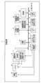
- FIG. 1 is a block diagram showing the configuration of the imaging apparatus 1.
- the imaging device 1 includes an imaging lens 2, a shutter 3, an imaging element 4 having an imaging element pixel MIX unit 11, a data bus 5, an internal memory 6, an AF signal processing unit 7, and an image signal processing unit. 8, a display unit 9, an input interface (IF) 10, an AF signal pixel MIX unit 12, an image signal pixel MIX unit 13, a MIX mode management / instruction unit 14, and a system control unit 15. I have.
- the external memory 20 is also illustrated in FIG. 1, the external memory 20 is configured by, for example, a memory card that can be attached to and detached from the imaging device 1. It doesn't matter.
- the imaging lens 2 is an imaging optical system that forms an optical image of a subject on the imaging device 4.
- the imaging lens 2 includes a focus lens for adjusting the focus position and an aperture for adjusting the light passage range.
- the imaging lens 2 may be a zoom lens that can adjust the zoom position.
- the shutter 3 is for adjusting the exposure time of the image sensor 4.
- the shutter 3 is provided on the optical path through which the optical image of the subject passes, and is an optical shutter that controls the arrival and shielding of the optical image to the image sensor 4 by, for example, opening and closing a light shielding curtain.
- the present invention is not limited to this, and a so-called electronic shutter may be used, or an optical shutter and an electronic shutter may be used in combination.
- the imaging device 4 is configured as, for example, a CMOS image sensor or a CCD image sensor, and has a plurality of pixels in which an optical image of a subject is arranged in a two-dimensional manner (each pixel includes a photodiode (PD) that performs photoelectric conversion).
- the image signal is generated by photoelectric conversion.
- the image pickup device 4 is a digital image pickup device that outputs a digital image signal.
- the image pickup device 4 is configured as an analog image pickup device, and an A between the image pickup device 4 and the data bus 5 is provided.
- a / D conversion unit may be provided separately.
- a plurality of types of pixels having different spectral characteristics are arranged in a first direction and a second direction perpendicular to the first direction as repetitions of the basic array, and any pixel is the first pixel.
- segmented into the some divided pixel of the some division position along a direction is provided.
- the image data generated by the pixel unit 4a is composed of a plurality of pixel data arranged in the first direction and the second direction, and each pixel data is along the first direction. It is composed of a plurality of divided pixel data.
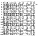
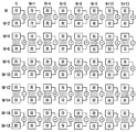
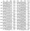
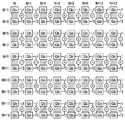
- FIG. 2 is a diagram showing the configuration of the divided pixels in the pixel portion 4a of the image sensor 4.
- FIG. 2 illustrates a pixel arrangement of vertical 20 ⁇ horizontal 8 pixels (vertical 20 ⁇ horizontal 16 divided pixels) in the pixel unit 4a, with row numbers M to (M + 19), and column numbers for the divided pixels are N. The part of (N + 15) is shown. Note that “row” is sometimes referred to as “line”.
- a plurality of types of pixels having different spectral characteristics are R (red) pixels, G (green) pixels (Gr pixels that are G pixels in the same row as the R pixels). , And G pixels in the same row as the B pixels) and B (blue) pixels, and the basic arrangement is the primary color Bayer arrangement (however, this is not restrictive).
- One pixel corresponding to one microlens ML is divided into two divided pixels (a right divided pixel and a left divided pixel) along the horizontal direction that is the first direction.
- so-called vertical line detection is performed by detecting the horizontal phase difference based on the right divided pixel group arranged in the horizontal direction and the left divided pixel group arranged in the horizontal direction. It is possible.
- the vertical phase difference Detection that is, so-called horizontal line detection can be performed.
- both vertical line detection and horizontal line detection can be performed.
- the upper left divided pixel and the lower left divided pixel are added and the upper right divided pixel and the lower right divided pixel are added in the configuration of the upper, lower, left, and right divided pixels, as shown in FIG. This is the same as the configuration of the left and right divided pixels.
- the upper left divided pixel and the upper right divided pixel are added, and the lower left divided pixel and the lower right divided pixel are added. Is equivalent to
- the data bus 5 is used to transmit various commands and data from one part in the imaging apparatus 1 to another part.
- the data bus 5 includes an image sensor 4, an internal memory 6, an AF signal processing unit 7, an image signal processing unit 8, a display unit 9, an input IF 10, and AF signal pixels.
- the MIX unit 12, the image signal pixel MIX unit 13, the MIX mode management / instruction unit 14, the system control unit 15, and the external memory 20 are connected.
- the internal memory 6 includes a volatile DRAM, a non-volatile flash memory, and the like, and stores and holds a processing program for controlling the entire imaging apparatus 1 in a non-volatile manner, as well as image data and user set values. Such as various data is temporarily or continuously stored and held.
- the processed image data and / or the image data processed by the image signal processing unit 8 are temporarily stored in the internal memory 6 as necessary, for example.
- AF signal processing unit 7 detects phase difference by processing such as differential calculation based on the divided pixel signal, calculates phase difference information, and generates lens drive information based on the calculated phase difference information.
- the lens drive information generated by the AF signal processing unit 7 is input to the system control unit 15.
- the system control unit 15 controls the focus position of the imaging lens 2 based on the input lens driving information, and focuses the subject image formed on the imaging device 4.
- the image signal processing unit 8 performs various processes such as white balance adjustment, demosaicing (color interpolation), color correction, ⁇ conversion, edge enhancement, noise reduction, resolution conversion (resizing), and image compression on the image data.
- the display unit 9 includes a display panel such as a TFT or an organic EL, for example, and is a display device that displays image data and various information related to the imaging device 1.
- the input IF 10 includes various operation input devices such as operation buttons, operation switches, and a touch panel, and is an operation unit for performing input to the imaging apparatus 1 when operated by a user.
- the input IF 10 includes, for example, a first button (so-called first release) and a second button (so-called second release) constituting a two-stage button for taking a still image, and a third button for taking a moving image. (Video recording button).
- the image sensor pixel MIX unit 11 reduces the number of pixels in the divided pixel signals of a plurality of adjacent divided pixels, which are related to the same type of pixel and the same divided position, to generate a processed pixel signal.
- This is a pixel reduction unit that reduces the number, and is an in-element pixel reduction unit provided in the image sensor 4.
- mixing mixing
- the present invention is not limited to this, and the pixels may be reduced by thinning (either mixing or thinning may be performed, or both may be performed).
- any of mixing by addition, mixing by addition average, mixing by weighted addition (or weighted addition average), and the like may be used.
- the imaging element pixel MIX unit 11 receives information on whether or not to mix from the MIX mode management / instruction unit 14, and receives information on what kind of mixing to perform when mixing, This is a pixel MIX section that performs a mix (MIX) process on pixel data in the image sensor 4.
- MIX mix
- the mixing process performed by the imaging element pixel MIX unit 11 includes a process of adding divided pixel signals from a plurality of divided pixels included in one pixel (in the case of the divided pixel configuration of FIG. 2, the left division of the same color). Left and right addition that adds the pixel and the right divided pixel to return to the normal pixel), vertical mix that mixes the divided pixel signals of a plurality of divided pixels having the same color and the same divided position adjacent in the vertical direction, and adjacent in the horizontal direction There is a horizontal mix that mixes divided pixel signals of a plurality of divided pixels having the same color and the same divided position.
- the divided pixel signal is output from the image sensor 4 as a phase difference signal. Is output.
- the image sensor pixel MIX unit 11 performs at least left-right addition (including a case where at least one of the vertical mix and horizontal mix is combined with left-right addition)
- the image sensor 4 receives phase difference information. A pixel signal for an image not included is output.
- the image data mixed by the imaging element pixel MIX unit 11 may be passed to each processing unit via the internal memory 6.
- the AF signal pixel MIX unit 12 is a pixel reduction unit provided outside the image sensor 4 and is output from the image sensor 4 after being mixed by the image sensor pixel MIX unit 11 as necessary. Pixels that receive information on whether or not to mix the image data from the MIX mode management / instruction unit 14 and, when mixing, information about what kind of mixing is to be performed, and that mix the pixel data It is a MIX section.
- the mix processing performed by the AF signal pixel MIX unit 12 includes the above-described vertical mix and horizontal mix, but for AF, the left divided pixel and the right divided pixel need to be separated. Does not include left-right addition.
- the image data mixed by the AF signal pixel MIX unit 12 is passed to the AF signal processing unit 7.
- the image signal pixel MIX unit 13 is a pixel reduction unit that reduces the number of pixels.
- the image signal pixel MIX unit 13 may generate an image signal and does not need phase difference information. Therefore, it is not necessary for the image signal pixel MIX unit 13 to reduce the number of pixels so as to leave the divided pixel signal, and it is sufficient to output a pixel signal obtained by adding left and right.
- the image signal pixel MIX unit 13 performs MIX mode management / instruction unit 14 on the image data output from the image sensor 4 after being mixed by the image sensor pixel MIX unit 11 as necessary.
- the information on whether to mix or not is received, and in the case of mixing, further information on what kind of mixing is performed is received, and the pixel data is mixed.
- the image signal pixel MIX unit 13 performs mix processing suitable for display images and moving images.
- the mix processing performed by the image signal pixel MIX unit 13 includes the above-described vertical mix, horizontal mix, and left-right addition.
- the image data mixed by the image signal pixel MIX unit 13 is passed to the image signal processing unit 8.
- the MIX mode management / instruction unit 14 is a control unit that controls pixel reduction by the pixel reduction unit in accordance with whether phase difference detection is prioritized.
- the MIX mode management / instruction unit 14 gives priority to phase difference detection, the arrangement interval in the direction (second direction) perpendicular to the division direction of the processed pixel signal (mixed pixel signal) is not equal. Thus, the pixel MIX unit is controlled.
- the MIX mode management / instruction unit 14 does not prioritize phase difference detection (for example, when image quality has priority over phase difference detection), and is a divided pixel of a plurality of divided pixels adjacent in the second direction.
- phase difference detection for example, when image quality has priority over phase difference detection
- the pixel MIX unit is controlled so that the arrangement intervals of the processed pixel signals in the second direction are equal.
- the MIX mode management / instruction unit 14 may reduce the number of divided pixel signals of a plurality of divided pixels adjacent in the first direction regardless of whether or not to give priority to phase difference detection.
- the pixel MIX unit is controlled so that the arrangement intervals of the processed pixel signals in the first direction are equal intervals.
- the MIX mode management / instruction unit 14 determines which mix (MIX) method (for example, the number of pixels to be mixed (number of divided pixels) or whether or not weighting is performed during mixing). ) Is optimal for image signal processing and optimal for AF signal processing, and the pixel MIX which is a pixel reduction unit depends on whether phase difference detection is prioritized or image quality is prioritized. This is a mix control unit for controlling the mix by the units (image sensor pixel MIX unit 11, AF signal pixel MIX unit 12, and image signal pixel MIX unit 13).
- MIX mix
- the determination of the mixing method by the MIX mode management / instruction unit 14 is performed based on, for example, the instruction of the input IF 10 (buttons, etc.), the exposure condition or subject information determined in the previous frame (however, other factors) May be determined based on).
- the external memory 20 is configured by, for example, a memory card that can be attached to and detached from the imaging apparatus 1, and stores an image processed for recording by the image signal processing unit 8, for example, in the form of an image file. It is a non-volatile recording medium.
- the system control unit 15 includes a processor configured by hardware such as a CPU, for example, and comprehensively controls the entire imaging apparatus 1 according to a processing program stored in the internal memory 6 in a nonvolatile manner.
- the system control unit 15 drives and controls the imaging lens 2 to change the focus position, the zoom state, the aperture diameter, and the like. Further, the system control unit 15 controls the driving of the shutter 3 to open and close the light-shielding curtain. Further, the system control unit 15 controls operations from accumulation of pixel signals by the image sensor 4 to output of image data.
- the imaging apparatus can perform the mix process (see FIGS. 3 to 10 and the like) giving priority to phase difference detection and the mix process (see FIGS. 11 to 15 and the like) giving priority to image quality. It is configured as follows.
- the spectral characteristics are of the same type (for example, the same color), excluding mixing processing of pixels of different colors and mixing of divided pixels of different division positions (left and right addition, etc.). ), And a mix process between divided pixels at the same division position (left division, right division, etc.) is considered.
- the left divided pixel and the right divided pixel are distinguished and mixed, and then the left divided pixel forming a pair.
- the right divided pixel and the right divided pixel have a positional relationship shifted by a half pixel pitch (one divided pixel pitch) in the horizontal direction even after mixing, and the Gr divided pixel and Gb divided pixel used in combination in phase difference detection are in the vertical direction after mixing. It is required to satisfy the conditions such as being close to each other (see FIGS. 4 and 8).
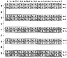
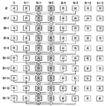
- FIG. 3 is a diagram illustrating an example of a vertical three-pixel mix related to an R-divided pixel that prioritizes phase difference detection.
- the row numbers and column numbers shown in FIG. 3 correspond to the row numbers and column numbers shown in FIG.
- the R-divided pixel obtained by dividing the R pixel in the left-right direction has ((M + 2i), (N + 4j)) and (row number, column number) when i and j are integers. (M + 2i), (N + 4j + 1)).
- three vertical R-divided pixels having the same column number and row numbers (M + 6i), (M + 6i + 2), and (M + 6i + 4) are added (or added).
- the average may be used, and so on.
- the added mixed pixels are arranged from the center of gravity of the three R-divided pixels in the vertical direction to the position of the center R-divided pixel, that is, the position where the row number is (M + 6i + 2).
- the MIX mode management / instruction unit 14 serving as the control unit includes the pixel MIX unit serving as the pixel reduction unit (the image sensor pixel MIX unit 11, the AF signal pixel MIX unit 12, and the image signal pixel MIX unit 13).
- the pixel MIX unit serving as the pixel reduction unit (the image sensor pixel MIX unit 11, the AF signal pixel MIX unit 12, and the image signal pixel MIX unit 13).
- the post-processing pixel signal (mix pixel) The center of gravity is set.
- the MIX mode management / instruction unit 14 specifies the position of the processed pixel signal by designating the positions of the divided pixels that remain without being thinned out when the small pixel reduction unit performs thinning out by thinning out. Set it.
- the vertical three-pixel mixing related to the Gr divided pixel, Gb divided pixel, and B divided pixel is performed as follows.
- Gr-divided pixels obtained by dividing Gr pixels in the horizontal direction are arranged at positions where (row number, column number) are ((M + 2i), (N + 4j + 2)) and ((M + 2i), (N + 4j + 3)). .
- the added mixed pixel is arranged at the position of the center Gr-divided pixel, that is, the position where the row number is (M + 6i + 2).
- the Gb divided pixels obtained by dividing the Gb pixel in the left-right direction are arranged at positions where (row number, column number) are ((M + 2i + 1), (N + 4j)) and ((M + 2i + 1), (N + 4j + 1)). Yes.
- the added mix pixel is arranged at the position of the central Gb-divided pixel, that is, the position where the row number is (M + 6i + 3).
- the B-divided pixels obtained by dividing the B pixel in the left-right direction are arranged at positions where (row number, column number) are ((M + 2i + 1), (N + 4j + 2)) and ((M + 2i + 1), (N + 4j + 3)). .
- FIG. 4 is a diagram showing a state in which the arrangement of the mix pixels obtained by the vertical three-pixel mix giving priority to phase difference detection is not equally spaced in the vertical direction.
- the G pixel mainly bears the luminance component, but as a result of performing the vertical three-pixel mixing that gives priority to the phase difference detection as described above, the Gr mixed pixel arranged in the row number (M + 6i + 2) and the row number ( The Gb mixed pixels arranged at M + 6i + 3) are dense in the vertical direction because they have only one row number. On the other hand, the Gb mix pixel arranged at the row number (M + 6i + 3) and the Gr mix pixel arranged at the row number (M + 6i + 8) are sparse in the vertical direction because the row numbers are different by five.
- the arrangement of the mix pixels is alternately dense and sparse in the vertical direction, and row numbers (M + 2) and (M + 3), (M + 8) and (M + 9), ... are dense, and row numbers (M + 3) and (M + 8), (M + 9) and (M + 14), ... are sparse.
- the Gb-divided pixels and Gr-divided pixels are arranged in consecutive column numbers N, (N + 1), (N + 2), (N + 3), (N + 4),.
- the arrangement density is double that of only the Gb-divided pixels in one row (or twice that of only the Gr-divided pixels in one row). Therefore, the detection accuracy is basically doubled as compared with the case where horizontal phase difference detection (that is, vertical line detection) is performed using only one row of G components.
- horizontal phase difference detection that is, vertical line detection
- the vertical shift between the Gb-divided pixel and the Gr-divided pixel is one row, the possibility of erroneous detection based on different vertical lines can be suppressed extremely small.
- the detection accuracy equivalent to the case where all the divided pixels shown in FIG. 2 are read out and the phase difference is detected using the Gb divided pixels and the Gr divided pixels is used. Can be obtained.
- FIG. 5 is a diagram illustrating an example of a vertical two-pixel mix related to an R-divided pixel that prioritizes phase difference detection.
- the vertical two-pixel mix related to the Gr-divided pixel, Gb-divided pixel, and B-divided pixel is performed as follows.
- the Gr divided pixels similar to the R divided pixels, two adjacent vertical Gr divided pixels such as (M + 4i) and (M + 4i + 2) are added.
- the added mixed pixels are arranged at an intermediate position, that is, a position where the row number is (M + 4i + 1), like the R-divided pixels.
- the B-divided pixel similarly to the Gb-divided pixel, two adjacent B-divided pixels in the vertical direction such as (M + 4i + 1) and (M + 4i + 3) are added.
- the added mix pixel is arranged at an intermediate position, that is, a position where the row number is (M + 4i + 2), similarly to the Gb divided pixel.
- the Gr mix pixel arranged at the row number (M + 4i + 1) and the Gb mix pixel arranged at the row number (M + 4i + 2) Is different in only one, so it is dense in the vertical direction.
- the Gb mix pixel arranged at the row number (M + 4i + 2) and the Gr mix pixel arranged at the row number (M + 4i + 5) are sparse in the vertical direction because they have three row numbers.
- the arrangement of the mix pixels is alternately dense and sparse in the vertical direction, and row numbers (M + 1) and (M + 2), (M + 5) and (M + 6),... M + 2) and (M + 5), (M + 6) and (M + 9), etc. are sparse.
- a third example of mixing processing (horizontal three-pixel mixing) giving priority to phase difference detection will be described with reference to FIGS. Note that three or more horizontal odd pixel mixes are also performed according to the method described here.
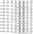
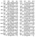
- FIG. 6 is a diagram illustrating an example of a horizontal three-pixel mix related to an R-divided pixel that prioritizes phase difference detection.
- the added mixed pixel is the position of the center R-divided pixel, that is, the position where the column number is (N + 12i + 4) for the R-left divided pixel, and the R-right divided pixel Are arranged at positions where the column number is (N + 12i + 5).
- FIG. 7 is a diagram illustrating an example of a horizontal three-pixel mix related to a Gr-divided pixel that prioritizes phase difference detection.
- three horizontal Gr left divided pixels having the same row number and the same column number (N + 12i + 6), (N + 12i + 10), (N + 12i + 14) are added.
- Three adjacent Gr right divided pixels in the horizontal direction such as (N + 12i + 7), (N + 12i + 11), and (N + 12i + 15) are added.
- the added mix pixel is the center Gr divided pixel position from the center of gravity of the three Gr divided pixels in the horizontal direction, that is, the position where the column number is (N + 12i + 10) for the Gr left divided pixel, and the Gr right divided pixel.
- the horizontal three-pixel mix for Gb pixels and B-divided pixels is performed as follows.
- the Gb-divided pixels three adjacent Gb left divided pixels in the horizontal direction such as column numbers (N + 12i), (N + 12i + 4), and (N + 12i + 8) are added, and the column numbers are (N + 12i + 1), ( Three adjacent Gb right divided pixels in the horizontal direction such as (N + 12i + 5) and (N + 12i + 9) are added.
- the added mix pixel is the center Gb divided pixel position from the center of gravity of the three Gb divided pixels in the horizontal direction, that is, the position where the column number is (N + 12i + 4) for the Gb left divided pixel, and the Gb right divided pixel. Are arranged at positions where the column number is (N + 12i + 5).
- the added mix pixel is the position of the center B-divided pixel from the barycentric position of the three B-divided pixels in the horizontal direction, that is, the position where the column number is (N + 12i + 10) for the B-left divided pixel, and the B-right divided pixel Are arranged at positions where the column number is (N + 12i + 11).
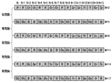
- FIG. 8 is a diagram showing an example in which the arrangement of the mix pixels obtained by the horizontal three-pixel mix giving priority to phase difference detection is equally spaced in the horizontal direction.
- the left divided pixel and the right divided pixel are divided and mixed, and the arrangement of the mix pixels is equally spaced in the horizontal direction (when only the mixed pixels related to the left divided pixel are viewed, they are equally spaced, Similarly, when only the mixed pixels related to the right divided pixel are viewed at equal intervals) (and as described above, the left divided pixel and the right divided pixel that form a pair are half-pixel pitch (although it is possible to perform phase difference detection (because the pixel division pitch is shifted)), it is possible to perform phase difference detection, but the horizontal pixel spacing is larger than the arrangement of mixed pixels as shown in FIG.
- the arrangement density in the horizontal direction is 1/3 of the arrangement in FIG. Therefore, in the case of the horizontal three-pixel mix as shown in FIG. 8, the phase difference detection accuracy of about 1/3 as compared with the case of the all-pixel readout or the vertical three-pixel mix shown in FIG. Since the phase difference detection accuracy is not determined only by the pixel arrangement density, the value of 1/3 is only from the viewpoint of the horizontal pixel arrangement density).
- a fourth example (horizontal two-pixel mix) of the mix process giving priority to phase difference detection will be described with reference to FIGS. Note that two or more horizontal even pixel mixes are also performed according to the method described here.
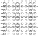
- FIG. 9 is a diagram illustrating an example in which a horizontal two-pixel mix related to an R-divided pixel that prioritizes phase difference detection is performed by weighted addition.
- two horizontal R left divided pixels having the same row number and column numbers (N + 8i) and (N + 8i + 4) are weighted and added at a ratio of 3: 1.
- the two adjacent R right divided pixels in the horizontal direction such as column numbers (N + 8i + 1) and (N + 8i + 5) are weighted and added at a ratio of 3: 1.
- the weights are transferred from the MIX mode management / instruction unit 14 to the pixel MIX unit (the image sensor pixel MIX unit 11, the AF signal pixel MIX unit 12, and the image signal pixel MIX unit 13) which is a pixel reduction unit. Instructed.
- the weighted mixed pixels are arranged at positions where the column number is (N + 8i + 1) for the R left divided pixel and at positions where the column number is (N + 8i + 2) for the R right divided pixel.
- the MIX mode management / instruction unit 14 as the control unit further specifies the mixture ratio of the divided pixel signals of the plurality of divided pixels to be mixed, thereby determining the barycentric position of the processed pixel signal (mixed pixel). It is set.
- FIG. 10 is a diagram illustrating an example in which a horizontal two-pixel mix related to a Gr-divided pixel giving priority to phase difference detection is performed by weighted addition.
- the two horizontal Gr left divided pixels in the horizontal direction having the same row number and the column numbers (N + 8i + 2) and (N + 8i + 6) are weighted and added 1: 3.
- the two horizontal Gr right divided pixels adjacent to each other such as column numbers (N + 8i + 3) and (N + 8i + 7) are weighted and added 1: 3.
- the weighted mixed pixels are arranged at a position where the column number is (N + 8i + 5) for the Gr left divided pixel and at a position where the column number is (N + 8i + 6) for the Gr right divided pixel.
- the horizontal two-pixel mix for Gb pixels and B-divided pixels is performed as follows.
- the two horizontal Gb left divided pixels adjacent to each other as column numbers (N + 8i) and (N + 8i + 4) are weighted and added 3: 1, and the column numbers are (N + 8i + 1), As shown in (N + 8i + 5), two adjacent Gb right divided pixels in the horizontal direction are weighted and added at a ratio of 3: 1.
- the weighted and added mix pixels are arranged at a position where the column number is (N + 8i + 1) for the Gb left divided pixel and at a position where the column number is (N + 8i + 2) for the Gb right divided pixel.
- two adjacent B left divided pixels in the horizontal direction such as column numbers (N + 8i + 2) and (N + 8i + 6) are weighted and added 1: 3, and the column number is (N + 8i + 3).
- (N + 8i + 7) and two adjacent B right divided pixels in the horizontal direction are weighted and added 1: 3.
- the weighted and added mix pixels are arranged at a position where the column number is (N + 8i + 5) for the B left divided pixel and at a position where the column number is (N + 8i + 6) for the B right divided pixel.
- the left divided pixel and the right divided pixel forming a pair are in a positional relationship shifted by a half pixel pitch (one divided pixel pitch) in the horizontal direction even after mixing, and the left divided pixel and the right divided pixel are also divided. Pairs with pixels are arranged at equal intervals in the horizontal direction.
- Mix processing giving priority to image quality for example, satisfies the condition that pairs of left divided pixels and right divided pixels used for phase difference detection are arranged at equal intervals in both the vertical and horizontal directions. Is required.
- FIG. 11 is a diagram showing an example of a vertical three-pixel mix related to an R-divided pixel giving priority to image quality.
- the vertical three-pixel mix related to the R-divided pixels is the same as the vertical three-pixel mix (FIG. 3) giving priority to phase difference detection.
- the vertical three-pixel mix related to the Gr-divided pixels is the same as the vertical three-pixel mix in which the phase difference detection is prioritized.
- FIG. 12 is a diagram showing an example of a vertical three-pixel mix related to Gb divided pixels giving priority to image quality.
- the vertical three-pixel mix related to the Gb-divided pixel three adjacent Gb-divided pixels in the vertical direction are added such as row numbers (M + 6i + 3), (M + 6i + 5), and (M + 6i + 7).
- the added mix pixel is arranged at the position of the central Gb divided pixel, that is, at the position where the row number is (M + 6i + 5).
- the vertical three-pixel mix related to the B-divided pixel three adjacent B-divided pixels in the vertical direction such as (M + 6i + 3), (M + 6i + 5), and (M + 6i + 7) are added as in the Gb-divided pixel. Is done.
- the added mix pixel is arranged at the position of the center B-divided pixel, that is, at the position where the row number is (M + 6i + 5), similarly to the Gb-divided pixel.
- FIG. 13 is a diagram illustrating a state in which the arrangement of the mix pixels obtained by the vertical three-pixel mix giving priority to image quality is equally spaced in the vertical direction.
- the row number of the Gb mix pixel and the B mix pixel added by the vertical three-pixel mix giving priority to the phase difference detection is (M + 6i + 3).
- the row number of the Gb mix pixel and the B mix pixel added by the vertical three-pixel mix giving priority to the image quality is (M + 6i + 5).
- the row numbers of the R mix pixel and the Gr mix pixel are both (M + 6i + 2) in FIGS.
- the Gr divided pixels and Gb divided pixels used in combination in the phase difference detection are in positions separated in the vertical direction. Although the accuracy is lowered, the luminance signal equivalent components are more uniformly distributed in the image because of the equal intervals, and the image quality can be improved.
- FIG. 14 is a diagram illustrating an example in which a vertical two-pixel mix related to an R-divided pixel giving priority to image quality is performed by weighted addition. The weight is instructed from the MIX mode management / instruction unit 14 in the same manner as described above.
- the vertical two-pixel mix related to the Gr-divided pixel giving priority to the image quality is also adjacent to the row numbers (M + 4i) and (M + 4i + 2) like the vertical two-pixel mix related to the R-divided pixel.
- Two Gr divided pixels in the vertical direction are weighted and added at a ratio of 3: 1.
- the weighted and added mix pixel is arranged at a position where the row number is (M + 4i + 0.5).
- FIG. 15 is a diagram illustrating an example in which a vertical two-pixel mix related to a Gb-divided pixel giving priority to image quality is performed by weighted addition.
- the adjacent two Gb-divided pixels in the vertical direction are weighted and added at 1: 3, such as row numbers (M + 4i + 1) and (M + 4i + 3).
- the weighted and added mix pixels are arranged at an intermediate position indicated by the hatching, that is, at a position where the row number is (M + 4i + 2.5).
- the vertical two-pixel mix related to the B-divided pixel giving priority to the image quality is also adjacent to the row numbers (M + 4i + 1) and (M + 4i + 3) like the vertical two-pixel mix related to the Gb-divided pixel.
- the two vertical B-divided pixels are weighted and added 1: 3.
- the weighted and added mix pixels are arranged at an intermediate position indicated by the hatching, that is, at a position where the row number is (M + 4i + 2.5).
- the R mix pixel and the Gr mix pixel are at positions where the row number is (M + 4i + 0.5), that is, (M + 0.5), (M + 4.5), (M + 8.5),. It is arranged at the position.
- the Gb mix pixel and the B mix pixel are arranged at positions where the row numbers are (M + 4i + 2.5), that is, (M + 2.5), (M + 6.5), (M + 10.5),. .
- the row of R mix pixels and Gr mix pixels and the row of Gb mix pixels and B mix pixels are separated by two pixels in the vertical direction at equal intervals.
- the third example of the mix process giving priority to image quality is the third example of the mix process giving priority to phase difference detection described with reference to FIGS. 6 to 8 (horizontal three-pixel mix). ) And the description thereof is omitted.
- the fourth example of the mix process giving priority to image quality is the fourth example of the mix process giving priority to phase difference detection described with reference to FIGS. 9 and 10 (horizontal two-pixel mix). ) And the description thereof is omitted.
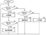
- FIG. 16 is a flowchart showing an operation at the time of photographing by the imaging apparatus 1.
- the operation at the time of shooting is performed by each unit in the imaging apparatus 1 based on the control of the system control unit 15.
- this process is entered after appropriate initial settings and the like are performed.
- the system control unit 15 determines whether or not the first button (first release) of the input IF 10 is turned on (step S1).
- step S2 when it is determined that the first button is turned on, AF processing as described later with reference to FIG. 17 is performed (step S2).
- the system control unit 15 next determines whether or not the second button (second release) is turned on (step S3).
- step S4 a still image process as described later with reference to FIG. 18 is performed.
- step S5 determines whether or not the third button (video recording button) is turned on.
- step S6 a moving image process as described later with reference to FIG. 19 is performed.
- step S7 If it is determined in step S5 that the third button is off, LV (live view) processing as will be described later with reference to FIG. 20 is performed (step S7).
- step S3 If it is determined in step S3 that the second button is off, the still image processing in step S4 is completed, the moving image processing in step S6 is completed, or the above-described step S7 is performed.
- the process returns to step S1 and the above-described process is repeated.
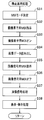
- FIG. 17 is a flowchart showing AF processing of the imaging apparatus 1.
- the system control unit 15 Upon entering this process in step S2 of FIG. 16, the system control unit 15 receives information indicating that the AF process has been performed, and the MIX mode management / instruction unit 14 uses the image sensor element from the viewpoint of giving priority to phase difference detection.
- the pixel MIX unit 11, the AF signal pixel MIX unit 12, and the image signal pixel MIX unit 13 each determine what kind of mixing processing is performed (step S11).
- the MIX mode management / instruction unit 14 instructs the mixing method in the imaging element pixel MIX unit 11 via the system control unit 15 (step S12).
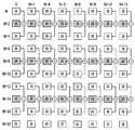
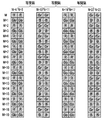
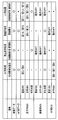
- FIG. 21 is a chart showing the mix processing classification according to AF, still image, moving image, and LV in the imaging apparatus 1 of the present embodiment.
- FIG. 22 shows the mix direction, the number of mixes, and the classification of non-equal spacing (sparse / dense arrangement) or equal spacing in each figure as shown in FIGS.
- FIG. 22 is a chart showing the correspondence between the mix process and each figure in the imaging apparatus 1 of the present embodiment.
- the MIX mode management / instruction unit 14 serving as the control unit has equal intervals in the second direction (the vertical direction in this example) of the processed pixel signals (mixed pixels) when phase difference detection is prioritized.
- control for reducing the number of divided pixel signals of a plurality of divided pixels adjacent to each other in the second direction is performed on at least the imaging element pixel MIX unit 11 which is an in-element small pixel unit. ing.
- the image data generated by the pixel unit 4a is mixed by the image sensor pixel MIX unit 11 (step S13) and read out from the image sensor 4 (step S14).
- the image data read from the image sensor 4 is transmitted to the AF signal pixel MIX unit 12 and the image signal pixel MIX unit 13, respectively.
- the processing of the image data transmitted to the image signal pixel MIX unit 13 is performed as follows.
- the MIX mode management / instruction unit 14 instructs the image signal pixel MIX unit 13 on the mixing method (step S15).
- the mix method instructed here includes left-right addition (see FIG. 21).
- the image signal pixel MIX unit 13 adds the left divided pixel and the right divided pixel of the same color to return to a normal pixel suitable for image signal processing (step S16).
- the image signal mixed for the image signal is transmitted from the image signal pixel MIX unit 13 to the image signal processing unit 8, and various image processing as described above is performed (step S17).
- the image signal subjected to the image processing is transmitted from the image signal processing unit 8 to the display unit 9 and displayed on the display unit 9 as an image (step S18).
- the processing of the image data transmitted to the AF signal pixel MIX unit 12 is performed as follows.
- the MIX mode management / instruction unit 14 instructs the AF signal pixel MIX unit 12 on the mixing method (step S21).
- the mix method instructed to the AF signal pixel MIX unit 12 does not perform the vertical mix already performed in the image sensor pixel MIX unit 11, for example, as shown in FIG. This is performed as shown in FIG.
- the reason why the horizontal mixing is further performed by the AF signal pixel MIX unit 12 is to improve the S / N assuming that the subject is dark, for example. Therefore, when the subject is brighter, the horizontal two-pixel mix of FIGS. 9 and 10 may be performed instead of the horizontal three-pixel mix of FIGS. 6 to 8, or when the subject is brighter, There is no need to perform a horizontal mix.
- the AF signal pixel MIX unit 12 mixes the image data received from the image sensor 4 in accordance with an instruction from the MIX mode management / instruction unit 14 (step S22).
- the image signal thus mixed for the AF signal is transmitted from the AF signal pixel MIX unit 12 to the AF signal processing unit 7, and processing such as differential calculation is performed by the AF signal processing unit 7 to obtain lens drive information. It is generated (step S23).
- the lens drive information generated by the AF signal processing unit 7 is transmitted to the system control unit 15, and the drive control of the imaging lens 2 by the system control unit 15 is performed for focusing (step S24).
- step S18 and step S24 the process returns from this process.
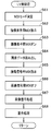
- FIG. 18 is a flowchart showing still image processing of the imaging apparatus 1.
- the MIX mode management / instruction unit 14 When entering this process in step S4 in FIG. 16, the MIX mode management / instruction unit 14 does not need to detect the phase difference (the image quality is prioritized). From the viewpoint, the image sensor pixel MIX unit 11, the AF signal pixel MIX unit 12, and the image signal pixel MIX unit 13 determine what kind of mixing processing is performed, respectively (step S31).
- the MIX mode management / instruction unit 14 instructs the mixing method in the imaging element pixel MIX unit 11 via the system control unit 15 (step S32).
- the mixing method instructed to the image sensor pixel MIX unit 11 is processing for performing left and right addition without performing vertical mixing and horizontal mixing, as shown in FIG. 21, for example.
- the mixing method instructed to the image sensor pixel MIX unit 11 is processing for performing left and right addition without performing vertical mixing and horizontal mixing, as shown in FIG. 21, for example.
- vertical mixing and horizontal mixing are not performed to prevent a decrease in the number of pixels.
- phase difference information is not required at the time of still image shooting, the number of pixels read from the image sensor 4 is reduced by performing left-right addition in the image sensor pixel MIX unit 11 to shorten the readout time. .
- the image data generated by the pixel unit 4a is mixed by the imaging element pixel MIX unit 11, the left divided pixel and the right divided pixel of the same color are added and returned to the normal pixel (step S33), Read from the image sensor 4 (step S34).
- the image data read from the image sensor 4 is transmitted to the image signal pixel MIX unit 13, but is transmitted to the AF signal pixel MIX unit 12. Not.
- the MIX mode management / instruction unit 14 instructs the image signal pixel MIX unit 13 to turn off the mix operation as shown in FIG. 21 (step S35). As described above, this is to avoid a reduction in the number of pixels due to the mix process.
- the image signal pixel MIX unit 13 turns off the mix operation (step S36).
- the image signal that has not been mixed by the image signal pixel MIX unit 13 and is output from the image sensor 4 in this way is transmitted to the image signal processing unit 8 via the image signal pixel MIX unit 13 or directly.
- various image processing as described above is performed (step S37).
- the image signal subjected to the image processing is transmitted from the image signal processing unit 8 to the external memory 20 and stored as an image file (still image file), for example, and transmitted to the display unit 9 to be displayed as an image (step S38). ).
- step S38 the process returns from this process.
- FIG. 19 is a flowchart showing the moving image processing of the imaging apparatus 1.
- the MIX mode management / instruction unit 14 gives priority to the image quality by receiving information from the system control unit 15 that the video processing has been completed (phase difference detection is necessary). However, from the viewpoint of giving priority to the image quality over the accuracy of phase difference detection), what kind of mixing processing each of the image sensor pixel MIX unit 11, the AF signal pixel MIX unit 12, and the image signal pixel MIX unit 13 performs? It is determined whether or not to perform (step S41).
- the MIX mode management / instruction unit 14 instructs the mixing method in the imaging element pixel MIX unit 11 via the system control unit 15 (step S42).
- the mixing method instructed to the image sensor pixel MIX unit 11 is performed, for example, as shown in FIG. 21, as shown in FIGS. 14 and 15 (that is, to prioritize image quality).
- the vertical mix pixels are equally spaced
- the horizontal mix is performed as shown in FIGS. 9 and 10 (horizontal mix pixels are equally spaced) (phase difference detection is required). Therefore, right and left addition is not naturally performed) (see also FIG. 22).
- the image data generated by the pixel unit 4a is mixed by the image sensor pixel MIX unit 11 (step S43) and read out from the image sensor 4 (step S44).
- the image data read from the image sensor 4 is transmitted to the AF signal pixel MIX unit 12 and the image signal pixel MIX unit 13, respectively.
- the processing of the image data transmitted to the image signal pixel MIX unit 13 is performed as follows.
- the MIX mode management / instruction unit 14 instructs the image signal pixel MIX unit 13 on the mixing method (step S45).
- the mixing method instructed here includes left-right addition.
- the image signal pixel MIX unit 13 adds the left divided pixel and the right divided pixel of the same color to return to a normal pixel suitable for image signal processing (step S46).
- the image signal mixed for the image signal is transmitted from the image signal pixel MIX unit 13 to the image signal processing unit 8, and various image processing as described above is performed (step S47).
- the image signal subjected to the image processing is transmitted from the image signal processing unit 8 to the external memory 20 and stored as, for example, an image file (moving image file), or transmitted to the display unit 9 and displayed as an image (step S48). .
- the processing of the image data transmitted to the AF signal pixel MIX unit 12 is performed as follows.
- the MIX mode management / instruction unit 14 instructs the AF signal pixel MIX unit 12 to turn off the mix operation (that is, turn off the vertical mix and horizontal mix), for example, as shown in FIG. 21 (step S51). This is because the vertical mix and the horizontal mix have already been performed in the imaging element pixel MIX unit 11.
- the AF signal pixel MIX unit 12 turns off the mix operation (step S52).
- the image signal that has not been mixed by the AF signal pixel MIX unit 12 and is output from the image sensor 4 in this way is transmitted to the AF signal processing unit 7 via the AF signal pixel MIX unit 12 or directly. Then, the AF signal processing unit 7 performs processing such as differential calculation to generate lens driving information (step S53).
- the lens drive information generated by the AF signal processing unit 7 is transmitted to the system control unit 15, and the drive control of the imaging lens 2 by the system control unit 15 is performed for focusing (step S54).
- step S48 and step S54 the process returns from this process.
- FIG. 20 is a flowchart showing processing for LV of the imaging apparatus 1.
- the MIX mode management / instruction unit 14 When entering this process in step S7 of FIG. 16, the MIX mode management / instruction unit 14 does not need to detect a phase difference (the image quality is prioritized) by receiving information from the system control unit 15 that the processing has become LV processing. From the viewpoint, the image pickup pixel MIX unit 11, the AF signal pixel MIX unit 12, and the image signal pixel MIX unit 13 each determine what kind of mixing processing is performed (step S61).
- the MIX mode management / instruction unit 14 instructs the mixing method in the imaging element pixel MIX unit 11 via the system control unit 15 (step S62).
- the mix method instructed to the image sensor pixel MIX unit 11 is performed as shown in FIGS. 11, 12, and 13, for example, as shown in FIG.
- the vertical mix pixels are equally spaced to give priority to the image)
- horizontal mixing is performed as shown in FIGS. 6, 7, and 8 (horizontal mix pixels are equally spaced)
- left and right addition is performed. It is a process to perform.
- the number of pixels read out from the image sensor 4 is determined by performing a vertical three-pixel mix and a horizontal three-pixel mix in the image sensor 4. Reducing power consumption.
- phase difference information is not required during LV image shooting, the number of pixels read out from the image sensor 4 is further reduced by performing left and right addition in the image sensor pixel MIX unit 11, thereby further shortening the readout time.
- the image data generated by the pixel unit 4a is mixed by the image sensor pixel MIX unit 11 (step S63) and read out from the image sensor 4 (step S64).
- the image data read from the image sensor 4 is transmitted to the image signal pixel MIX unit 13 but is not transmitted to the AF signal pixel MIX unit 12. .
- the MIX mode management / instruction unit 14 instructs the image signal pixel MIX unit 13 to turn off the mix operation, as shown in FIG. 21 (step S65). This is because the necessary mix processing has already been performed by the imaging element pixel MIX unit 11.
- the image signal pixel MIX unit 13 turns off the mix operation (step S66).
- step S67 The image signal that has not been mixed by the image signal pixel MIX unit 13 and is output from the image sensor 4 in this way is transmitted to the image signal processing unit 8 via the image signal pixel MIX unit 13 or directly.
- various image processing as described above is performed (step S67).
- the image signal subjected to the image processing is transmitted from the image signal processing unit 8 to the display unit 9 and displayed on the display unit 9 as an image (step S68).
- step S68 the process returns from this process.
- the first direction is mainly the horizontal direction and the second direction is the vertical direction
- the phase difference detection (vertical line detection) in the horizontal direction has been described as an example.
- the arrangement intervals of the processed pixel signals in the vertical direction are not equal. Also, when reducing the number of pixels in the horizontal direction (horizontal mix or horizontal thinning) without reducing the number of pixels in the vertical direction, or when reducing the number of pixels in the horizontal direction in addition to the number of pixels in the vertical direction. In the same manner as in general processing, the horizontal alignment intervals of the processed pixel signals are made equal.
- the pixel MIX portion that is the pixel reduction portion
- the image sensor pixel MIX portion 11 in-element MIX
- the image signal pixel MIX portion 13 image MIX
- the AF signal pixel MIX portion 12 Although an example provided with three (MIX for AF) (example of combination of (4) below) has been described, it is not limited to providing all three.
- the number of divided pixel signals of a plurality of divided pixels adjacent in the second direction is reduced so that the arrangement intervals of the processed pixel signals in the second direction are not equal.
- the following combinations are possible ( ⁇ : OK, ⁇ : NG).
- the AF signal pixel MIX unit 12 the number of pixels is reduced with the first direction as the horizontal direction and the second direction as the vertical direction, and a post-process pixel signal for vertical line detection is generated to detect vertical lines.
- the AF signal pixel MIX unit 12 reduces the number of pixels with the first direction as the vertical direction and the second direction as the horizontal direction, and the processed pixel signal for horizontal line detection. May be generated to detect the horizontal line.
- the AF signal pixel MIX unit 12 mixes the pixels as fewer pixels. If processing is performed, it is possible to improve sensitivity (S / N).
- the Bayer array is taken as an example of the basic pixel array.
- the present invention is not limited to this.
- RGB pixels are exemplified as pixels having different spectral characteristics.
- the present invention is not limited to this. It may be a complementary color pixel, may include a white pixel, or may be a multicolor pixel of three or more colors.
- the phase difference detection is performed using the signal of the G pixel mainly responsible for the luminance component.
- the phase difference detection is performed after the demosaicing process is performed to generate the luminance signal at each pixel position. It doesn't matter.
- the number of divided pixel signals is reduced so that the arrangement intervals in the second direction of the processed pixel signals are not equal. Furthermore, the arrangement intervals in the second direction of the processed pixel signals of the type used for phase difference detection can be made closer, and erroneous detection based on different subjects can be effectively suppressed. Thus, the number of pixels can be reduced and the phase difference detection accuracy can be improved.
- the arrangement interval of the processed pixel signals in the second direction is made equal, so that the luminance signal equivalent component is distributed more uniformly in the image. , Image quality can be improved.
- the image quality in the first direction can be improved regardless of whether or not the phase difference detection is prioritized.
- the imaging element pixel MIX unit 11 which is an in-element reduction unit so that the arrangement intervals of the processed pixel signals in the second direction do not become equal intervals, Since the number of pixels read out from the image sensor 4 can be reduced, reading out can be performed at high speed and power consumption can be reduced.
- the position of the center of gravity of the post-processing pixel signal is set by designating the positions of a plurality of divided pixels to be mixed, for example, an address designation type imaging device capable of designating a readout row or readout pixel 4, it is possible to suitably perform the processing in the element.
- each part mentioned above may be comprised as a circuit. Any circuit may be mounted as a single circuit or a combination of a plurality of circuits as long as it can perform the same function. Furthermore, an arbitrary circuit is not limited to being configured as a dedicated circuit for performing a target function, and may be configured to perform a target function by causing a general-purpose circuit to execute a processing program. . Alternatively, a processor configured as hardware may perform processing of each unit as a processing step.
- the imaging apparatus is mainly described.
- an imaging method that performs the same processing as the imaging apparatus may be used, and a processing program for causing a computer to perform the same processing as the imaging apparatus and the processing program are recorded. It may be a non-temporary recording medium that can be read by a computer.
- the present invention is not limited to the above-described embodiment as it is, and can be embodied by modifying the constituent elements without departing from the scope of the invention in the implementation stage.
- various aspects of the invention can be formed by appropriately combining a plurality of components disclosed in the embodiment. For example, some components may be deleted from all the components shown in the embodiment.
- constituent elements over different embodiments may be appropriately combined.
Landscapes
- Engineering & Computer Science (AREA)
- Multimedia (AREA)
- Signal Processing (AREA)
- Physics & Mathematics (AREA)
- General Physics & Mathematics (AREA)
- Spectroscopy & Molecular Physics (AREA)
- Optics & Photonics (AREA)
- Automatic Focus Adjustment (AREA)
- Focusing (AREA)
- Studio Devices (AREA)
- Color Television Image Signal Generators (AREA)
- Transforming Light Signals Into Electric Signals (AREA)
Priority Applications (2)
| Application Number | Priority Date | Filing Date | Title |
|---|---|---|---|
| CN201780082457.3A CN110169054B (zh) | 2017-01-10 | 2017-10-25 | 摄像装置、摄像方法 |
| US16/457,864 US10911701B2 (en) | 2017-01-10 | 2019-06-28 | Image pickup apparatus and image pickup method |
Applications Claiming Priority (2)
| Application Number | Priority Date | Filing Date | Title |
|---|---|---|---|
| JP2017001882A JP6847669B2 (ja) | 2017-01-10 | 2017-01-10 | 撮像装置、撮像方法 |
| JP2017-001882 | 2017-01-10 |
Related Child Applications (1)
| Application Number | Title | Priority Date | Filing Date |
|---|---|---|---|
| US16/457,864 Continuation US10911701B2 (en) | 2017-01-10 | 2019-06-28 | Image pickup apparatus and image pickup method |
Publications (1)
| Publication Number | Publication Date |
|---|---|
| WO2018131254A1 true WO2018131254A1 (ja) | 2018-07-19 |
Family
ID=62840281
Family Applications (1)
| Application Number | Title | Priority Date | Filing Date |
|---|---|---|---|
| PCT/JP2017/038461 Ceased WO2018131254A1 (ja) | 2017-01-10 | 2017-10-25 | 撮像装置、撮像方法 |
Country Status (4)
| Country | Link |
|---|---|
| US (1) | US10911701B2 (enExample) |
| JP (1) | JP6847669B2 (enExample) |
| CN (1) | CN110169054B (enExample) |
| WO (1) | WO2018131254A1 (enExample) |
Families Citing this family (3)
| Publication number | Priority date | Publication date | Assignee | Title |
|---|---|---|---|---|
| JP7086783B2 (ja) * | 2018-08-13 | 2022-06-20 | 株式会社東芝 | 固体撮像装置 |
| EP4270934A4 (en) | 2021-02-10 | 2024-06-05 | Samsung Electronics Co., Ltd. | ELECTRONIC DEVICE COMPRISING AN IMAGE SENSOR AND ITS OPERATING METHOD |
| US20240021634A1 (en) * | 2022-07-14 | 2024-01-18 | Visera Technologies Company Limited | Image sensor and method for reducing image signal processor |
Citations (3)
| Publication number | Priority date | Publication date | Assignee | Title |
|---|---|---|---|---|
| JP2015173387A (ja) * | 2014-03-12 | 2015-10-01 | キヤノン株式会社 | 撮像素子、その駆動方法、およびプログラム |
| JP2015195550A (ja) * | 2014-03-28 | 2015-11-05 | パナソニックIpマネジメント株式会社 | 撮像素子および撮像装置 |
| JP2016213757A (ja) * | 2015-05-12 | 2016-12-15 | キヤノン株式会社 | 撮像装置およびその制御方法 |
Family Cites Families (7)
| Publication number | Priority date | Publication date | Assignee | Title |
|---|---|---|---|---|
| JP5888914B2 (ja) * | 2011-09-22 | 2016-03-22 | キヤノン株式会社 | 撮像装置およびその制御方法 |
| JP5853594B2 (ja) * | 2011-10-31 | 2016-02-09 | ソニー株式会社 | 情報処理装置、情報処理方法およびプログラム |
| JP6264616B2 (ja) * | 2013-01-30 | 2018-01-24 | パナソニックIpマネジメント株式会社 | 撮像装置及び固体撮像装置 |
| JP5923075B2 (ja) * | 2013-10-07 | 2016-05-24 | モレックス エルエルシー | コネクタ |
| WO2015141084A1 (ja) * | 2014-03-18 | 2015-09-24 | 富士フイルム株式会社 | 撮像装置及び合焦制御方法 |
| KR102390836B1 (ko) * | 2015-10-05 | 2022-04-26 | 삼성전자주식회사 | 이미지 데이터를 생성하는 전자 장치 및 방법 |
| JP6741549B2 (ja) * | 2016-10-14 | 2020-08-19 | キヤノン株式会社 | 撮像装置及びその制御方法 |
-
2017
- 2017-01-10 JP JP2017001882A patent/JP6847669B2/ja active Active
- 2017-10-25 CN CN201780082457.3A patent/CN110169054B/zh active Active
- 2017-10-25 WO PCT/JP2017/038461 patent/WO2018131254A1/ja not_active Ceased
-
2019
- 2019-06-28 US US16/457,864 patent/US10911701B2/en active Active
Patent Citations (3)
| Publication number | Priority date | Publication date | Assignee | Title |
|---|---|---|---|---|
| JP2015173387A (ja) * | 2014-03-12 | 2015-10-01 | キヤノン株式会社 | 撮像素子、その駆動方法、およびプログラム |
| JP2015195550A (ja) * | 2014-03-28 | 2015-11-05 | パナソニックIpマネジメント株式会社 | 撮像素子および撮像装置 |
| JP2016213757A (ja) * | 2015-05-12 | 2016-12-15 | キヤノン株式会社 | 撮像装置およびその制御方法 |
Also Published As
| Publication number | Publication date |
|---|---|
| CN110169054A (zh) | 2019-08-23 |
| US10911701B2 (en) | 2021-02-02 |
| JP2018113542A (ja) | 2018-07-19 |
| CN110169054B (zh) | 2021-10-08 |
| US20190327434A1 (en) | 2019-10-24 |
| JP6847669B2 (ja) | 2021-03-24 |
Similar Documents
| Publication | Publication Date | Title |
|---|---|---|
| US8471952B2 (en) | Image pickup apparatus | |
| US8525917B2 (en) | Image sensing apparatus with plural focus detection pixel groups | |
| CN103168463B (zh) | 图像传感器和摄像设备 | |
| US8823851B2 (en) | Image capturing apparatus and control method for image capturing apparatus | |
| US10630920B2 (en) | Image processing apparatus | |
| US9843735B2 (en) | Image processing apparatus, imaging apparatus comprising the same, and image processing method | |
| US9654681B2 (en) | Electronic apparatus and method of controlling the same | |
| AU2012374649A1 (en) | Image processing device, image-capturing element, image processing method, and program | |
| WO2012114819A1 (ja) | 撮像装置、および撮像装置制御方法、並びにプログラム | |
| US20150116538A1 (en) | Method and apparatus for imaging an object | |
| US8872963B2 (en) | Imaging apparatus and imaging method | |
| JP6166562B2 (ja) | 撮像素子及びその駆動方法、及び撮像装置 | |
| JPH10336686A (ja) | 撮像装置 | |
| JP2017216647A (ja) | 撮像素子、撮像装置、および撮像信号処理方法 | |
| JP6070301B2 (ja) | 固体撮像素子及びこれを用いた撮像装置 | |
| JP4738907B2 (ja) | 固体撮像素子および固体撮像装置 | |
| WO2013047158A1 (ja) | 撮像装置及び合焦制御方法 | |
| US10911701B2 (en) | Image pickup apparatus and image pickup method | |
| JPWO2012147515A1 (ja) | 撮像装置及び撮像方法 | |
| JP5033711B2 (ja) | 撮像装置及び撮像装置の駆動方法 | |
| JP5600812B2 (ja) | 撮像装置 | |
| JP7084801B2 (ja) | 撮像素子および撮像装置 | |
| CN107819979B (zh) | 摄像元件、摄像装置 | |
| JP6393087B2 (ja) | 撮像素子及び撮像装置 | |
| JP2006148591A (ja) | 固体撮像装置および固体撮像素子駆動方法 |
Legal Events
| Date | Code | Title | Description |
|---|---|---|---|
| 121 | Ep: the epo has been informed by wipo that ep was designated in this application |
Ref document number: 17891148 Country of ref document: EP Kind code of ref document: A1 |
|
| NENP | Non-entry into the national phase |
Ref country code: DE |
|
| 122 | Ep: pct application non-entry in european phase |
Ref document number: 17891148 Country of ref document: EP Kind code of ref document: A1 |