WO2018127961A1 - Dispositif de division de puce de capture d'échantillon - Google Patents
Dispositif de division de puce de capture d'échantillon Download PDFInfo
- Publication number
- WO2018127961A1 WO2018127961A1 PCT/JP2017/000177 JP2017000177W WO2018127961A1 WO 2018127961 A1 WO2018127961 A1 WO 2018127961A1 JP 2017000177 W JP2017000177 W JP 2017000177W WO 2018127961 A1 WO2018127961 A1 WO 2018127961A1
- Authority
- WO
- WIPO (PCT)
- Prior art keywords
- chip
- space
- sample
- cut
- cutout
- Prior art date
Links
Images


Classifications
-
- G—PHYSICS
- G01—MEASURING; TESTING
- G01N—INVESTIGATING OR ANALYSING MATERIALS BY DETERMINING THEIR CHEMICAL OR PHYSICAL PROPERTIES
- G01N1/00—Sampling; Preparing specimens for investigation
- G01N1/02—Devices for withdrawing samples
- G01N1/10—Devices for withdrawing samples in the liquid or fluent state
- G01N1/18—Devices for withdrawing samples in the liquid or fluent state with provision for splitting samples into portions
-
- A—HUMAN NECESSITIES
- A61—MEDICAL OR VETERINARY SCIENCE; HYGIENE
- A61B—DIAGNOSIS; SURGERY; IDENTIFICATION
- A61B10/00—Other methods or instruments for diagnosis, e.g. instruments for taking a cell sample, for biopsy, for vaccination diagnosis; Sex determination; Ovulation-period determination; Throat striking implements
- A61B10/0045—Devices for taking samples of body liquids
-
- G—PHYSICS
- G01—MEASURING; TESTING
- G01N—INVESTIGATING OR ANALYSING MATERIALS BY DETERMINING THEIR CHEMICAL OR PHYSICAL PROPERTIES
- G01N1/00—Sampling; Preparing specimens for investigation
- G01N1/28—Preparing specimens for investigation including physical details of (bio-)chemical methods covered elsewhere, e.g. G01N33/50, C12Q
-
- G—PHYSICS
- G01—MEASURING; TESTING
- G01N—INVESTIGATING OR ANALYSING MATERIALS BY DETERMINING THEIR CHEMICAL OR PHYSICAL PROPERTIES
- G01N33/00—Investigating or analysing materials by specific methods not covered by groups G01N1/00 - G01N31/00
- G01N33/48—Biological material, e.g. blood, urine; Haemocytometers
- G01N33/483—Physical analysis of biological material
- G01N33/487—Physical analysis of biological material of liquid biological material
- G01N33/49—Blood
- G01N33/491—Blood by separating the blood components
Definitions
- the present invention has a suction port on one end side, and has a flow channel for holding a sample such as blood sucked from the suction port, and a necessary part of the sample collected in the flow channel is constant.
- the present invention relates to an instrument that handles a sampling chip configured to be divided into quantities, and particularly to an instrument that is used when dividing such a sampling chip.
- a small amount of blood collection tube consisting of a capillary with both ends opened is used.
- blood is aspirated into the micro blood collection tube, and the tip is sealed with a putty or the like, followed by centrifugation. Thereafter, the blood collection tube is folded and cut in the vicinity of the interface between the plasma portion and the blood cell portion, and only the plasma component is taken out by being transferred to a capillary having a predetermined volume.
- the extracted plasma component is appropriately treated and then analyzed by TLC (thin layer chromatograph), LC (liquid chromatograph), LC / MS (liquid chromatograph / mass spectrometer), mass spectrometer and the like.
- centrifuge tube intended to collect only a small amount of leukocyte portion between the centrifuged blood cell portion and plasma portion (see Patent Document 1).
- the centrifuge tube has a small-diameter and small-volume reservoir between two large and large reservoirs.
- the lower large-capacity reservoir is bottomed and the upper large-capacity reservoir is released by an opening.
- a predetermined amount of blood is collected from the upper release portion and then centrifuged, the white blood cell portion comes to the small volume reservoir.
- a fine glass tube capillary
- the white blood cell component in the small volume reservoir is collected.
- a disk is provided with several flow paths including capillaries, the disk is centrifuged to separate blood components, and reacted with a reagent for detection.
- an instrument used therefor for example, an instrument composed of a disk-shaped member having an integrally molded chamber, a channel, a reservoir, and an analysis cell has been proposed (see Patent Document 2).
- a blood sample is introduced into the instrument and centrifuged to separate the blood cells from the serum, which is then subjected to several processing steps and tests.
- the present inventors have proposed and implemented a sample collection chip capable of accurately collecting a very small amount of sample (see Patent Document 3).
- a sample can be collected in a flow path provided therein, and then held in a predetermined holder as it is to perform centrifugation.
- this sample collection chip is provided with a slit on the outer surface so that it can be folded by an analyst's hand and cut off a necessary part of the flow path, and can be divided into a plurality of parts. Thereby, a necessary fixed amount of the samples separated in the internal flow path can be easily taken out.
- the sample in the flow path may be scattered to the outside due to an impact when the slit portion is broken.
- the sample in the flow path may be scattered to the outside due to an impact when the slit portion is broken.
- the sample in the flow path may be scattered to the outside due to an impact when the slit portion is broken.
- the sample in the flow path may be scattered to the outside due to an impact when the slit portion is broken.
- the sample in the flow path may be scattered to the outside due to an impact when the slit portion is broken.
- there is a possibility of a biohazard so it is necessary to pay attention to scattered matter.
- segmenting into several parts there exists a problem that it is difficult to cut out the part if the length of the part to take out is short.
- an object of the present invention is to provide an instrument that can easily divide a sampling chip while preventing scattering of an internal sample.
- the sample collection chip dividing instrument has a sample collection channel inside, and at least one that can be cut out at a position of a cut-out slit provided on the outer surface to cut out a part of the channel.
- the sample collection tip splitting device for cutting out the cutout portion of the sample collection tip that has two cutout portions and can cut out the cutout portion by folding the cutout portion at a position of the cutout slit.
- the sample collecting chip dividing instrument has a main body block, an opening provided in the main body block and leading to the outer surface of the main body block, and the cutout portion of the sample collecting chip is fitted through the opening.
- a space part for receiving the sample scattered from the broken part of the sample-collecting chip provided around the opening outside the space part and divided in the vicinity of the opening; I have.
- the space portion has a position where the opening of the space portion is formed by the slit for cutting provided on the outer surface of the sample-collecting chip in order to cut the cut portion when the cut portion is inserted into the space portion.
- the depth dimension is set so that it may come to the position of the outer side of the said space part slightly more than it.
- the thickness dimension of the space portion needs to be substantially the same as or larger than the thickness dimension of the cutout portion fitted into the space portion, but the thickness dimension of the space portion is larger than the thickness dimension of the cutout portion of the sampling chip. If it is too large, it becomes difficult to apply a stress to the target position when the sample collection tip is bent. Therefore, it is preferable that the thickness dimension of the space portion is at most slightly larger than the thickness dimension of the cutout portion fitted into the space portion. “Slightly large” means that a gap generated between the inner wall of the space portion and the cut portion fitted in the space portion is, for example, 2 mm or less.
- the enclosure portion is provided on the outer surface of the main body block, communicates with the space portion, and the sampling chip with the cutout portion fitted in the space portion is folded in the bending direction. It is a recess having a dimension that can be applied. With such a configuration, the enclosure can be provided with a simple configuration, and therefore the sample collection chip dividing instrument of the present invention can be easily and inexpensively produced.
- the sample collection tip splitting instrument of the present invention can also be applied when the sample collection tip has a plurality of the cutout portions.
- the main body block is provided with a plurality of the space portions and the surrounding portions individually corresponding to the cutout portions of the sample collection tip.
- the opening of each space portion leads to different side surfaces of the main body block.
- the opening of each space portion leads to different side surfaces of the main body block means that openings for inserting the respective cutout portions of the sample collection chip are provided on a plurality of surfaces of the main body block. .
- the main body block has an opening that is provided inside the main body block and communicates with the outer surface of the main body block, and a cutout portion of the sample collection chip is fitted through the opening.
- a cut-out portion can be cut from the sampling tip. Thereby, it is easy to cut the cut portion from the sample collection tip.
- an enclosure is provided around the opening outside the space to receive the sample scattered from the fractured portion of the sample-collecting chip divided in the vicinity of the opening, so that the cut-out part is cut out from the sample-collecting chip. It is possible to prevent the occurrence of problems such as biohazard by stopping the scattering of the sample around the sample by the surrounding portion.
- FIG. 1B is a cross-sectional view at the YY position in FIG. 1A. It is sectional drawing which shows the state which fitted the 1st cutting part of the sampling chip
- the sample collection chip 102 includes a chip body 104, and the chip body 104 includes a lower substrate 106 and an upper substrate 108.
- the lower substrate 106 and the upper substrate 108 are integrated by bonding to constitute the chip body 104.
- a sample-collecting flow path 110 is formed on the bonding surface of the upper substrate 108, and the flow path 110 is arranged in the chip body 104 by bonding the lower substrate 106 and the upper substrate 108.
- the chip body 104 has a proximal end 112 and a distal end 114.
- the sample collection chip 102 performs a centrifugal separation process after sucking the sample, and the sample collection chip 102 is applied to the centrifuge so that the centrifugal force acts in the direction from the base end 112 to the tip end 114 at that time. Installed.
- the term “base end” or “tip end” of the chip body 104 is determined based on the direction of the centrifugal force.
- the chip body 104 has a sample suction port 116 on the proximal end side.
- the sample suction port 116 is provided as an opening that communicates with a recess 118 provided at the base end 112 of the chip body 104.
- the concave portion 118 is for facilitating the suction of the sample from the sample suction port 116 when the tip 114 is brought into contact with a sample such as blood during sample collection.
- the flow path 110 has such a thickness that can suck a sample by capillary action.
- the flow path 110 is connected by a connecting portion 120 on the distal end side in the chip body 104, and has two flow path portions 110a and 110b extending from the distal end side to the proximal end side.
- One channel portion 110 a has an introduction channel 110 c, and the introduction channel 110 c communicates with the sample suction port 16.
- the other flow path portion 110 b terminates at a position that does not reach the base end 112.
- a liquid pool space 110d is provided at the end of the flow path portion 110b.
- the liquid reservoir space 110d has at least a cross-sectional area large enough not to suck liquid by capillary action, and the air hole 122 is a base of the liquid reservoir space 110d. It leads to the end side end.
- the liquid storage space 110d has an internal capacity that is equal to or greater than the internal capacity of the portion of the introduction flow path 110c of the flow path portion 110a that is on the base end side (upper side in the drawing) of the air hole 122.
- the cross-sectional area of the inlet of the liquid pool space 110d is, for example, twice or more the cross-sectional area of the other part of the flow path part 110b.
- An example of the cross-sectional dimension of the inlet portion of the liquid pool space 10d is about 3 mm in width and about 1.5 mm in depth.
- Advantages of providing the liquid pool space 110d at the end of the flow path portion 110b include the following.
- the sample sucked from the sample suction port 116 does not reach the position of the air hole 122 and stops at the inlet portion of the liquid pool space 110d. . Thereby, the sample collection amount in the flow path portions 110a and 110b can be ensured without increasing the amount of the sample collected in the extraction unit 110.
- the sample collection chip 102 of this embodiment is provided with a collection portion 124 on the proximal end side and a wide portion 126 on the distal end side.
- the width dimension and the thickness dimension of the sampling part 124 are smaller than the width dimension and the thickness dimension of the wide part 126.
- Three cutting slits 128a, 128b, and 128c that are orthogonal to the direction in which the sampling portion 124 (channel 110) extends are provided on the upper surface and the lower surface of the sampling portion 124, respectively.
- the cutting slit 128c is provided at the boundary between the sampling portion 124 and the wide portion 126.
- the cut slit 128a is provided at a position on the tip side of the air hole 122, and the cut slit 128b is provided at a position between the cut slits 128a and 128c.
- the sampling unit 124 can be divided into three cutting units 130, 131, and 132. If stress is applied to the sampling chip 102 so as to be folded at the position of the cut slit 126a, the cut portion 130 can be cut, and if stress is applied so as to be folded at the position of the cut slit 126b, the cut portion 131 is obtained. If a stress is applied so as to be folded at the position of the cut slit 126c, the cut portion 132 can be cut.
- the cutout portions 131 and 132 include two flow passage portions 110a and 110b. By cutting the cutout portions 131 and 132, the cutout portions 131 and 132 are held in the flow passage portions 110a and 110b of the cutout portions 131 and 132. A certain amount of sample can be easily taken out.
- the cut-out parts 131 and 132 Since the position where the cut-out parts 131 and 132 are arranged in the collection part 124 is on the base end side, when the collected sample is subjected to a centrifugal separation process, the cut-out parts 131 and 132 have a low specific gravity that is centrifuged. The other component is located. For example, when blood is collected as a sample and subjected to a centrifugal separation process so that the distal end side of the sample collection chip 102 is in the direction in which the centrifugal force acts, the cut portions 131 and 132 have plasma components or serum. The positions of the cutout portions 131 and 132 in the flow path 110 are set so that the components come.
- the wide part 126 has such a size that identification information such as the name and number of the sample collected on the sample collection chip can be entered and a label filled with the identification information can be attached.
- the wide portion 126 can also be used as a gripping portion when the sample collection tip is held.
- the sample collection chip 102 is made of, for example, a resin material.
- the resin material is not particularly limited.
- COP cycloolefin polymer
- PMMA polymethyl methacrylate resin
- PP polypropylene resin
- PC polycarbonate resin
- PVA polyvinyl alcohol
- the channel 110 sucks a liquid sample from the sample inlet 116 by capillary action, the cross-sectional area of the channel 110 is not only thin enough to cause capillary action, but also when the sample is blood or an aqueous solution. Requires that the inner surface of the channel 110 be hydrophilic. Since the resin material exemplified above is hydrophobic, the inner surface of the flow path 110 and the sample suction port 116 are preferably treated so as to be hydrophilic.
- an anticoagulant that prevents blood coagulation is provided on the inner surface of the flow path 110 in order to suck blood directly from the specimen and collect plasma in the cutout portion 130 by centrifugation. It is preferable.
- the anticoagulant may be coated on the inner surface of the flow path 110 after coating with a hydrophilic polymer.
- the cut-out part 131 (and 132) is separated from the chip body 104 and becomes separate cut-out parts 131 and 132 in order to use the cut-out part 131 (and 132) for analysis after centrifugation.
- the tip body 104 is sequentially folded at the positions of the cut slits 128a, 128b, and 128c. In this way, two samples for analysis can be obtained from one chip body 104. Generally, the most proximal-side cutout 130 is an unnecessary part and is discarded.
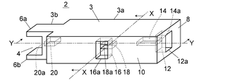
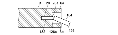
- FIGS. 1A to 1C An example of a sample-collecting chip dividing tool for assisting the cutting of each of the cutting portions 130, 131, 132 from the sample-collecting chip 102 will be described with reference to FIGS. 1A to 1C.
- the sample collection chip dividing instrument 2 of this embodiment includes a main body block 3, space portions 14, 18 and 20 provided inside the main body block 3, and a concave portion forming an enclosure provided on the outer surface of the main body block 3. 4, 12 and 16.
- the material of the main body block 3 may be any material as long as it is equivalent to or harder than the sampling chip 102, such as vinyl chloride or polypropylene.
- the main body block 3 includes a substantially rectangular parallelepiped portion 3a and a narrow portion 3b projecting from one end of the substantially rectangular parallelepiped portion 3a with a width dimension narrower than that of the substantially rectangular parallelepiped portion 3a.
- the side where the narrow portion 3b is provided in the main body block 3 is the distal end side, and the side opposite to the narrow portion 3b is the proximal end side.
- a recess 4 is provided on the front end surface of the narrow portion 3b of the main body block 3 over the entire width of the narrow portion 3b. Thereby, the cross-sectional shape of the narrow part 3b is U-shaped.
- An opening 20a leading to the space 20 is provided on the bottom surface of the recess 4 of the narrow portion 3b.
- a rectangular opening 12 a leading to the recess 12 is provided on the side surface 8 on the base end side of the main body block 3.
- An opening 14 a that leads to the space portion 14 is provided in the innermost surface of the recess 12.
- a rectangular opening 16 a leading to the recess 16 is provided on the side surface 10 orthogonal to the surface 8 of the main body block 3.
- An opening 18 a that communicates with the space 18 is provided on the innermost surface of the recess 16.
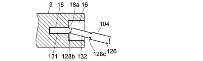
- the space portion 14 is for fitting a cutout portion 130 (see FIGS. 6A to 6C) located on the most proximal side of the sample collection chip 102.
- the space portion 14 is inserted into the cutout portion 130, and the tip body 104 of the sample collection tip 102 is folded at the position of the cutout slit 28a, thereby making the cutout portion 130 the sample collection tip 102.
- the height dimension of the recess 12 (the vertical dimension in FIGS. 1C and 2B) is such that the chip body 104 with the cutout 130 fitted in the space 14 can be folded at the position of the cutout slit 28a. Designed with various dimensions.
- the depth dimension (the dimension in the left-right direction in FIG. 1C) of the space portion 14 is designed to be slightly shorter (for example, about 1 mm) than the length dimension of the cutout portion 130.
- the cutout slit 28 a is disposed at a position slightly outside the edge of the opening 14 a of the space portion 14 and inside the recess 12.
- FIG. 2B when the main body chip 104 is folded at the position of the cut-off slit 28a, the inner peripheral surface of the recess 12 receives the liquid scattered from the fracture surface, and the liquid to the surroundings is received. Is prevented from scattering.
- the height dimension (the vertical dimension in FIG. 1C) of the space portion 14 is approximately the same as the thickness dimension of the cut-out portion 130, slightly larger than it, or slightly (for example, (0.1 mm) It should be designed to have a small dimension. Since the cutout part 130 is an unnecessary part that is not used for analysis, the cutout part 130 may remain accommodated in the main body block 3. Therefore, if the height dimension of the space portion 14 is designed to be slightly smaller than the thickness dimension of the cut portion 130, the cut portion 130 after being cut from the chip body 104 can be left in the main body block 3.
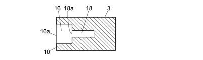
- the space 18 is used to fit the cut-out portion 131 (see FIGS. 6A to 6C) of the sample-collecting chip 102 after the cut-out portion 130 is cut out. .
- the space 18 is used to cut out the cut-out portion 131 from the sample-collecting tip 102 by fitting the cut-out portion 131 and folding the chip body 104 at the position of the cut-out slit 28b. Is done.
- the height of the recess 16 (the vertical dimension in FIGS. 1B and 3B) is such that the chip body 104 with the cutout 131 fitted in the space 16 can be folded at the position of the cutout slit 28b. Designed with various dimensions.
- the depth dimension (the dimension in the left-right direction in FIG. 1B) of the space 18 is designed to be slightly shorter (for example, about 1 mm) than the length dimension of the cutout 131.
- the height dimension of the space part 18 (the vertical dimension in FIG. 1B) is substantially the same as the thickness dimension of the cut part 131, or it can be removed so that the cut part 131 can be removed from the space part 18.
- the dimensions are designed to be slightly larger than the above.
- the space portion 20 is for fitting a cutout portion 132 (see FIGS. 6A to 6C) of the sample collection chip 102 after the cutout portion 131 is cut out.
- the space portion 20 is used to cut out the cutout portion 132 from the sample collection tip 102 by fitting the cutout portion 132 and folding the chip body 104 at the position of the cutout slit 28c. Is done.
- the height of the recess 4 (the vertical dimension in FIGS. 1C and 4B) is such that the chip body 104 with the cutout 132 fitted in the space 20 can be folded at the position of the cutout slit 28c. Designed with various dimensions.
- the depth dimension of the space part 20 (the dimension in the left-right direction in FIG. 1C) is designed to be slightly shorter (for example, about 1 mm) than the length dimension of the cutout part 132.
- the cutout slit 28 c is disposed at a position slightly outside the edge of the opening 20 a of the space portion 20 and inside the recess 4.
- FIG. 4B when the main body chip 104 is folded at the position of the cut slit 28c, the protrusions 6a and 6b sandwiching the recess 4 become wrinkles and the liquid scattered from the fracture surface The liquid is prevented from splashing around.
- the height dimension of the space part 20 (the vertical dimension in FIG. 1B) is substantially the same as the thickness dimension of the cut part 132 so that the cut-out part 132 can be removed from the space part 20 or
- the size is designed to be slightly larger than that.
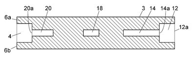
- the recesses 12, 16 and 4 are provided on the outer surface of the main body block 3, and the spaces 14, 18, and 20 are provided on the back side of the recesses, whereby the recess 12 , 16 and 4 are used as enclosures for receiving liquid scattered from the fracture surface of the main body chip 104.
- the enclosure for receiving the liquid scattered from the fracture surface of the main body chip 104 is not limited to such a recess.
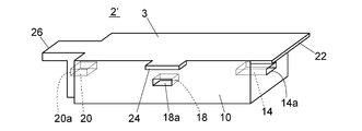
- the sample collection chip splitting device 2 ′ of the embodiment shown in FIG. 5 is provided with openings 14 a, 18 a and 20 a communicating with the space portions 14, 18 and 20 on the outer surface of the main body block 3.
- openings 14 a, 18 a and 20 a communicating with the space portions 14, 18 and 20 on the outer surface of the main body block 3.
- 22, 24 and 26 are provided.
- the flanges 22, 24 and 26 are provided only on one side of the openings 14a, 18a and 20a, but they may be provided so as to sandwich the openings 14a, 18a and 20a.
- sampling chip splitting device 2, 2 ′ of the embodiment described above is provided so that each space portion 14, 18 and 20 leads to a different side surface of the main body block 3, but the present invention is It is not limited to this, You may provide so that it may mutually lead to the same side surface.
Abstract
L'invention concerne un dispositif de division d'une puce de capture d'échantillon comprenant : un bloc principal ; un espace prévu à l'intérieur du bloc principal et présentant une ouverture qui s'ouvre sur la surface externe du bloc principal, et qui, à travers le trou, vient en prise avec la partie encoche de la puce de capture d'échantillon, ce qui permet de stocker ce dernier ; et une partie périphérique qui est disposée à la périphérie de l'ouverture sur l'extérieur de l'espace, et qui est destinée à recevoir des échantillons qui ont été projetés à partir d'une partie rompue de la puce de capture d'échantillon divisée à proximité de l'ouverture.
Priority Applications (4)
| Application Number | Priority Date | Filing Date | Title |
|---|---|---|---|
| PCT/JP2017/000177 WO2018127961A1 (fr) | 2017-01-05 | 2017-01-05 | Dispositif de division de puce de capture d'échantillon |
| JP2018560291A JP6696592B2 (ja) | 2017-01-05 | 2017-01-05 | 試料採取チップ分割用器具 |
| US16/475,465 US11467069B2 (en) | 2017-01-05 | 2017-01-05 | Sampling chip dividing instrument |
| EP17889652.8A EP3567360B1 (fr) | 2017-01-05 | 2017-01-05 | Dispositif de division de puce de capture d'échantillon |
Applications Claiming Priority (1)
| Application Number | Priority Date | Filing Date | Title |
|---|---|---|---|
| PCT/JP2017/000177 WO2018127961A1 (fr) | 2017-01-05 | 2017-01-05 | Dispositif de division de puce de capture d'échantillon |
Publications (1)
| Publication Number | Publication Date |
|---|---|
| WO2018127961A1 true WO2018127961A1 (fr) | 2018-07-12 |
Family
ID=62791019
Family Applications (1)
| Application Number | Title | Priority Date | Filing Date |
|---|---|---|---|
| PCT/JP2017/000177 WO2018127961A1 (fr) | 2017-01-05 | 2017-01-05 | Dispositif de division de puce de capture d'échantillon |
Country Status (4)
| Country | Link |
|---|---|
| US (1) | US11467069B2 (fr) |
| EP (1) | EP3567360B1 (fr) |
| JP (1) | JP6696592B2 (fr) |
| WO (1) | WO2018127961A1 (fr) |
Cited By (3)
| Publication number | Priority date | Publication date | Assignee | Title |
|---|---|---|---|---|
| JP2020095004A (ja) * | 2018-12-06 | 2020-06-18 | 株式会社シン・コーポレイション | 毛細管折断具及び微量試料採取器具 |
| WO2020208672A1 (fr) * | 2019-04-08 | 2020-10-15 | 株式会社島津製作所 | Dispositif de collecte d'échantillon |
| JP7202042B1 (ja) | 2022-04-30 | 2023-01-11 | 慶應義塾 | 医療機器及びその製造方法 |
Citations (6)
| Publication number | Priority date | Publication date | Assignee | Title |
|---|---|---|---|---|
| JPS457226B1 (fr) * | 1967-07-14 | 1970-03-12 | ||
| JPH01199159A (ja) | 1988-02-04 | 1989-08-10 | Kosumitsuku:Kk | 遠心チューブ |
| JPH02122800U (fr) * | 1989-03-16 | 1990-10-09 | ||
| JP2001502793A (ja) | 1996-09-28 | 2001-02-27 | セントラル リサーチ ラボラトリーズ リミティド | 化学分析用の装置及び方法 |
| JP2012518157A (ja) * | 2009-02-17 | 2012-08-09 | エフ.ホフマン−ラ ロシュ アーゲー | 血液成分を提供する方法及び装置 |
| WO2016009720A1 (fr) | 2014-07-18 | 2016-01-21 | 株式会社島津製作所 | Dispositif de collecte à volume constant au moyen d'une centrifugation ou pour davantage de stockage |
Family Cites Families (12)
| Publication number | Priority date | Publication date | Assignee | Title |
|---|---|---|---|---|
| NL137565C (fr) * | 1965-07-15 | |||
| US5095792A (en) * | 1989-12-04 | 1992-03-17 | Ernest Moody | Device for cutting microhematocrit tubes |
| RU2258922C2 (ru) * | 2000-03-28 | 2005-08-20 | Дайэбитиз Дайэгностикс, Инк | Одноразовые электрохимические датчики |
| US6855243B2 (en) * | 2001-04-27 | 2005-02-15 | Lifescan, Inc. | Electrochemical test strip having a plurality of reaction chambers and methods for using the same |
| US20030211619A1 (en) * | 2002-05-09 | 2003-11-13 | Lorin Olson | Continuous strip of fluid sampling and testing devices and methods of making, packaging and using the same |
| US20040086869A1 (en) * | 2002-10-31 | 2004-05-06 | Schembri Carol T. | Device having multiple molecular arrays |
| US8153081B2 (en) * | 2003-05-29 | 2012-04-10 | Bayer Healthcare Llc | Test sensor and method for manufacturing the same |
| US20050100880A1 (en) * | 2003-11-12 | 2005-05-12 | Yu-Hong Chang | Biosensor test strips of multiple function for multiple uses |
| JP2005342118A (ja) * | 2004-06-01 | 2005-12-15 | Toru Yagyu | 刃物用具及び刃物 |
| ATE544519T1 (de) * | 2004-12-13 | 2012-02-15 | Bayer Healthcare Llc | Unabhängiger testsensor |
| GB2511760B (en) * | 2013-03-11 | 2015-07-01 | Suresensors Ltd | Improvements relating to test devices |
| WO2017122314A1 (fr) * | 2016-01-14 | 2017-07-20 | 株式会社島津製作所 | Dispositif de prélèvement d'échantillon, support de dispositif de prélèvement d'échantillon et procédé de prétraitement d'échantillons qui utilise le dispositif de prélèvement d'échantillon |
-
2017
- 2017-01-05 WO PCT/JP2017/000177 patent/WO2018127961A1/fr unknown
- 2017-01-05 JP JP2018560291A patent/JP6696592B2/ja active Active
- 2017-01-05 US US16/475,465 patent/US11467069B2/en active Active
- 2017-01-05 EP EP17889652.8A patent/EP3567360B1/fr active Active
Patent Citations (6)
| Publication number | Priority date | Publication date | Assignee | Title |
|---|---|---|---|---|
| JPS457226B1 (fr) * | 1967-07-14 | 1970-03-12 | ||
| JPH01199159A (ja) | 1988-02-04 | 1989-08-10 | Kosumitsuku:Kk | 遠心チューブ |
| JPH02122800U (fr) * | 1989-03-16 | 1990-10-09 | ||
| JP2001502793A (ja) | 1996-09-28 | 2001-02-27 | セントラル リサーチ ラボラトリーズ リミティド | 化学分析用の装置及び方法 |
| JP2012518157A (ja) * | 2009-02-17 | 2012-08-09 | エフ.ホフマン−ラ ロシュ アーゲー | 血液成分を提供する方法及び装置 |
| WO2016009720A1 (fr) | 2014-07-18 | 2016-01-21 | 株式会社島津製作所 | Dispositif de collecte à volume constant au moyen d'une centrifugation ou pour davantage de stockage |
Non-Patent Citations (1)
| Title |
|---|
| See also references of EP3567360A4 |
Cited By (8)
| Publication number | Priority date | Publication date | Assignee | Title |
|---|---|---|---|---|
| JP2020095004A (ja) * | 2018-12-06 | 2020-06-18 | 株式会社シン・コーポレイション | 毛細管折断具及び微量試料採取器具 |
| JP7152022B2 (ja) | 2018-12-06 | 2022-10-12 | 株式会社シン・コーポレイション | 毛細管折断具及び微量試料採取器具 |
| WO2020208672A1 (fr) * | 2019-04-08 | 2020-10-15 | 株式会社島津製作所 | Dispositif de collecte d'échantillon |
| JPWO2020208672A1 (ja) * | 2019-04-08 | 2021-12-16 | 株式会社島津製作所 | 試料採取デバイス |
| JP7248105B2 (ja) | 2019-04-08 | 2023-03-29 | 株式会社島津製作所 | 試料採取デバイス |
| JP7202042B1 (ja) | 2022-04-30 | 2023-01-11 | 慶應義塾 | 医療機器及びその製造方法 |
| WO2023210761A1 (fr) * | 2022-04-30 | 2023-11-02 | 慶應義塾 | Instrument médical et son procédé de fabrication |
| JP2023164208A (ja) * | 2022-04-30 | 2023-11-10 | 慶應義塾 | 医療機器及びその製造方法 |
Also Published As
| Publication number | Publication date |
|---|---|
| US11467069B2 (en) | 2022-10-11 |
| JP6696592B2 (ja) | 2020-05-20 |
| JPWO2018127961A1 (ja) | 2019-11-07 |
| EP3567360B1 (fr) | 2023-06-28 |
| EP3567360A4 (fr) | 2020-08-26 |
| EP3567360A1 (fr) | 2019-11-13 |
| US20210131920A1 (en) | 2021-05-06 |
Similar Documents
| Publication | Publication Date | Title |
|---|---|---|
| US10962450B2 (en) | Specimen collection device, holder for specimen collection device, and specimen pre-processing method that uses specimen collection device | |
| JP6288274B2 (ja) | 遠心分離による定容量分取又はさらに保管のための器具 | |
| EP1690085B1 (fr) | Dispositif de prelevement d'echantillons liquides jetable | |
| JP2021501340A (ja) | 液体試料採取装置 | |
| WO2018127961A1 (fr) | Dispositif de division de puce de capture d'échantillon | |
| EP2777499A1 (fr) | Dispositif de collecte d'échantillon de fluide rotatif | |
| EP2778679A1 (fr) | Dispositif de collecte d'échantillon de fluide en forme de disque rotatif | |
| CN111133311B (zh) | 血液采集器具 | |
| JP6104440B1 (ja) | 血液採取器及び血液収容器を含む血液採取器具 | |
| CN108291907B (zh) | 用于血液样品保存和红细胞比容分离的系统及方法 | |
| US11333583B2 (en) | Sample extraction tool | |
| JP7174723B2 (ja) | 流体収集ユニットならびに関連のデバイスおよび方法 | |
| JP6658498B2 (ja) | 遠心分離用試料ホルダ | |
| EP3223945B1 (fr) | Dispositif compact a base de verre pour analyse de fluid et procédé de fabrication | |
| US11684915B2 (en) | Compact fluid analysis device and method to fabricate | |
| EP3308859A1 (fr) | Dispositif destiné à collecter et/ou à manipuler un échantillon liquide et à séparer ledit échantillon liquide en différents composants et son procédé d'utilisation | |
| CN111542741A (zh) | 流体处理方法和该方法中使用的流体处理装置以及流体处理系统 | |
| US20210001344A1 (en) | Sample holding disc for centrifugation | |
| JP3460140B2 (ja) | 溝を有する毛細管により液体試料を分析する試験具 |
Legal Events
| Date | Code | Title | Description |
|---|---|---|---|
| 121 | Ep: the epo has been informed by wipo that ep was designated in this application |
Ref document number: 17889652 Country of ref document: EP Kind code of ref document: A1 |
|
| ENP | Entry into the national phase |
Ref document number: 2018560291 Country of ref document: JP Kind code of ref document: A |
|
| NENP | Non-entry into the national phase |
Ref country code: DE |
|
| ENP | Entry into the national phase |
Ref document number: 2017889652 Country of ref document: EP Effective date: 20190805 |