WO2018127961A1 - Device for dividing sample-capture chip - Google Patents
Device for dividing sample-capture chip Download PDFInfo
- Publication number
- WO2018127961A1 WO2018127961A1 PCT/JP2017/000177 JP2017000177W WO2018127961A1 WO 2018127961 A1 WO2018127961 A1 WO 2018127961A1 JP 2017000177 W JP2017000177 W JP 2017000177W WO 2018127961 A1 WO2018127961 A1 WO 2018127961A1
- Authority
- WO
- WIPO (PCT)
- Prior art keywords
- chip
- space
- sample
- cut
- cutout
- Prior art date
Links
Images


Classifications
-
- G—PHYSICS
- G01—MEASURING; TESTING
- G01N—INVESTIGATING OR ANALYSING MATERIALS BY DETERMINING THEIR CHEMICAL OR PHYSICAL PROPERTIES
- G01N1/00—Sampling; Preparing specimens for investigation
- G01N1/02—Devices for withdrawing samples
- G01N1/10—Devices for withdrawing samples in the liquid or fluent state
- G01N1/18—Devices for withdrawing samples in the liquid or fluent state with provision for splitting samples into portions
-
- A—HUMAN NECESSITIES
- A61—MEDICAL OR VETERINARY SCIENCE; HYGIENE
- A61B—DIAGNOSIS; SURGERY; IDENTIFICATION
- A61B10/00—Other methods or instruments for diagnosis, e.g. instruments for taking a cell sample, for biopsy, for vaccination diagnosis; Sex determination; Ovulation-period determination; Throat striking implements
- A61B10/0045—Devices for taking samples of body liquids
-
- G—PHYSICS
- G01—MEASURING; TESTING
- G01N—INVESTIGATING OR ANALYSING MATERIALS BY DETERMINING THEIR CHEMICAL OR PHYSICAL PROPERTIES
- G01N1/00—Sampling; Preparing specimens for investigation
- G01N1/28—Preparing specimens for investigation including physical details of (bio-)chemical methods covered elsewhere, e.g. G01N33/50, C12Q
-
- G—PHYSICS
- G01—MEASURING; TESTING
- G01N—INVESTIGATING OR ANALYSING MATERIALS BY DETERMINING THEIR CHEMICAL OR PHYSICAL PROPERTIES
- G01N33/00—Investigating or analysing materials by specific methods not covered by groups G01N1/00 - G01N31/00
- G01N33/48—Biological material, e.g. blood, urine; Haemocytometers
- G01N33/483—Physical analysis of biological material
- G01N33/487—Physical analysis of biological material of liquid biological material
- G01N33/49—Blood
- G01N33/491—Blood by separating the blood components
Definitions
- the present invention has a suction port on one end side, and has a flow channel for holding a sample such as blood sucked from the suction port, and a necessary part of the sample collected in the flow channel is constant.
- the present invention relates to an instrument that handles a sampling chip configured to be divided into quantities, and particularly to an instrument that is used when dividing such a sampling chip.
- a small amount of blood collection tube consisting of a capillary with both ends opened is used.
- blood is aspirated into the micro blood collection tube, and the tip is sealed with a putty or the like, followed by centrifugation. Thereafter, the blood collection tube is folded and cut in the vicinity of the interface between the plasma portion and the blood cell portion, and only the plasma component is taken out by being transferred to a capillary having a predetermined volume.
- the extracted plasma component is appropriately treated and then analyzed by TLC (thin layer chromatograph), LC (liquid chromatograph), LC / MS (liquid chromatograph / mass spectrometer), mass spectrometer and the like.
- centrifuge tube intended to collect only a small amount of leukocyte portion between the centrifuged blood cell portion and plasma portion (see Patent Document 1).
- the centrifuge tube has a small-diameter and small-volume reservoir between two large and large reservoirs.
- the lower large-capacity reservoir is bottomed and the upper large-capacity reservoir is released by an opening.
- a predetermined amount of blood is collected from the upper release portion and then centrifuged, the white blood cell portion comes to the small volume reservoir.
- a fine glass tube capillary
- the white blood cell component in the small volume reservoir is collected.
- a disk is provided with several flow paths including capillaries, the disk is centrifuged to separate blood components, and reacted with a reagent for detection.
- an instrument used therefor for example, an instrument composed of a disk-shaped member having an integrally molded chamber, a channel, a reservoir, and an analysis cell has been proposed (see Patent Document 2).
- a blood sample is introduced into the instrument and centrifuged to separate the blood cells from the serum, which is then subjected to several processing steps and tests.
- the present inventors have proposed and implemented a sample collection chip capable of accurately collecting a very small amount of sample (see Patent Document 3).
- a sample can be collected in a flow path provided therein, and then held in a predetermined holder as it is to perform centrifugation.
- this sample collection chip is provided with a slit on the outer surface so that it can be folded by an analyst's hand and cut off a necessary part of the flow path, and can be divided into a plurality of parts. Thereby, a necessary fixed amount of the samples separated in the internal flow path can be easily taken out.
- the sample in the flow path may be scattered to the outside due to an impact when the slit portion is broken.
- the sample in the flow path may be scattered to the outside due to an impact when the slit portion is broken.
- the sample in the flow path may be scattered to the outside due to an impact when the slit portion is broken.
- the sample in the flow path may be scattered to the outside due to an impact when the slit portion is broken.
- the sample in the flow path may be scattered to the outside due to an impact when the slit portion is broken.
- there is a possibility of a biohazard so it is necessary to pay attention to scattered matter.
- segmenting into several parts there exists a problem that it is difficult to cut out the part if the length of the part to take out is short.
- an object of the present invention is to provide an instrument that can easily divide a sampling chip while preventing scattering of an internal sample.
- the sample collection chip dividing instrument has a sample collection channel inside, and at least one that can be cut out at a position of a cut-out slit provided on the outer surface to cut out a part of the channel.
- the sample collection tip splitting device for cutting out the cutout portion of the sample collection tip that has two cutout portions and can cut out the cutout portion by folding the cutout portion at a position of the cutout slit.
- the sample collecting chip dividing instrument has a main body block, an opening provided in the main body block and leading to the outer surface of the main body block, and the cutout portion of the sample collecting chip is fitted through the opening.
- a space part for receiving the sample scattered from the broken part of the sample-collecting chip provided around the opening outside the space part and divided in the vicinity of the opening; I have.
- the space portion has a position where the opening of the space portion is formed by the slit for cutting provided on the outer surface of the sample-collecting chip in order to cut the cut portion when the cut portion is inserted into the space portion.
- the depth dimension is set so that it may come to the position of the outer side of the said space part slightly more than it.
- the thickness dimension of the space portion needs to be substantially the same as or larger than the thickness dimension of the cutout portion fitted into the space portion, but the thickness dimension of the space portion is larger than the thickness dimension of the cutout portion of the sampling chip. If it is too large, it becomes difficult to apply a stress to the target position when the sample collection tip is bent. Therefore, it is preferable that the thickness dimension of the space portion is at most slightly larger than the thickness dimension of the cutout portion fitted into the space portion. “Slightly large” means that a gap generated between the inner wall of the space portion and the cut portion fitted in the space portion is, for example, 2 mm or less.
- the enclosure portion is provided on the outer surface of the main body block, communicates with the space portion, and the sampling chip with the cutout portion fitted in the space portion is folded in the bending direction. It is a recess having a dimension that can be applied. With such a configuration, the enclosure can be provided with a simple configuration, and therefore the sample collection chip dividing instrument of the present invention can be easily and inexpensively produced.
- the sample collection tip splitting instrument of the present invention can also be applied when the sample collection tip has a plurality of the cutout portions.
- the main body block is provided with a plurality of the space portions and the surrounding portions individually corresponding to the cutout portions of the sample collection tip.
- the opening of each space portion leads to different side surfaces of the main body block.
- the opening of each space portion leads to different side surfaces of the main body block means that openings for inserting the respective cutout portions of the sample collection chip are provided on a plurality of surfaces of the main body block. .
- the main body block has an opening that is provided inside the main body block and communicates with the outer surface of the main body block, and a cutout portion of the sample collection chip is fitted through the opening.
- a cut-out portion can be cut from the sampling tip. Thereby, it is easy to cut the cut portion from the sample collection tip.
- an enclosure is provided around the opening outside the space to receive the sample scattered from the fractured portion of the sample-collecting chip divided in the vicinity of the opening, so that the cut-out part is cut out from the sample-collecting chip. It is possible to prevent the occurrence of problems such as biohazard by stopping the scattering of the sample around the sample by the surrounding portion.
- FIG. 1B is a cross-sectional view at the YY position in FIG. 1A. It is sectional drawing which shows the state which fitted the 1st cutting part of the sampling chip
- the sample collection chip 102 includes a chip body 104, and the chip body 104 includes a lower substrate 106 and an upper substrate 108.
- the lower substrate 106 and the upper substrate 108 are integrated by bonding to constitute the chip body 104.
- a sample-collecting flow path 110 is formed on the bonding surface of the upper substrate 108, and the flow path 110 is arranged in the chip body 104 by bonding the lower substrate 106 and the upper substrate 108.
- the chip body 104 has a proximal end 112 and a distal end 114.
- the sample collection chip 102 performs a centrifugal separation process after sucking the sample, and the sample collection chip 102 is applied to the centrifuge so that the centrifugal force acts in the direction from the base end 112 to the tip end 114 at that time. Installed.
- the term “base end” or “tip end” of the chip body 104 is determined based on the direction of the centrifugal force.
- the chip body 104 has a sample suction port 116 on the proximal end side.
- the sample suction port 116 is provided as an opening that communicates with a recess 118 provided at the base end 112 of the chip body 104.
- the concave portion 118 is for facilitating the suction of the sample from the sample suction port 116 when the tip 114 is brought into contact with a sample such as blood during sample collection.
- the flow path 110 has such a thickness that can suck a sample by capillary action.
- the flow path 110 is connected by a connecting portion 120 on the distal end side in the chip body 104, and has two flow path portions 110a and 110b extending from the distal end side to the proximal end side.
- One channel portion 110 a has an introduction channel 110 c, and the introduction channel 110 c communicates with the sample suction port 16.
- the other flow path portion 110 b terminates at a position that does not reach the base end 112.
- a liquid pool space 110d is provided at the end of the flow path portion 110b.
- the liquid reservoir space 110d has at least a cross-sectional area large enough not to suck liquid by capillary action, and the air hole 122 is a base of the liquid reservoir space 110d. It leads to the end side end.
- the liquid storage space 110d has an internal capacity that is equal to or greater than the internal capacity of the portion of the introduction flow path 110c of the flow path portion 110a that is on the base end side (upper side in the drawing) of the air hole 122.
- the cross-sectional area of the inlet of the liquid pool space 110d is, for example, twice or more the cross-sectional area of the other part of the flow path part 110b.
- An example of the cross-sectional dimension of the inlet portion of the liquid pool space 10d is about 3 mm in width and about 1.5 mm in depth.
- Advantages of providing the liquid pool space 110d at the end of the flow path portion 110b include the following.
- the sample sucked from the sample suction port 116 does not reach the position of the air hole 122 and stops at the inlet portion of the liquid pool space 110d. . Thereby, the sample collection amount in the flow path portions 110a and 110b can be ensured without increasing the amount of the sample collected in the extraction unit 110.
- the sample collection chip 102 of this embodiment is provided with a collection portion 124 on the proximal end side and a wide portion 126 on the distal end side.
- the width dimension and the thickness dimension of the sampling part 124 are smaller than the width dimension and the thickness dimension of the wide part 126.
- Three cutting slits 128a, 128b, and 128c that are orthogonal to the direction in which the sampling portion 124 (channel 110) extends are provided on the upper surface and the lower surface of the sampling portion 124, respectively.
- the cutting slit 128c is provided at the boundary between the sampling portion 124 and the wide portion 126.
- the cut slit 128a is provided at a position on the tip side of the air hole 122, and the cut slit 128b is provided at a position between the cut slits 128a and 128c.
- the sampling unit 124 can be divided into three cutting units 130, 131, and 132. If stress is applied to the sampling chip 102 so as to be folded at the position of the cut slit 126a, the cut portion 130 can be cut, and if stress is applied so as to be folded at the position of the cut slit 126b, the cut portion 131 is obtained. If a stress is applied so as to be folded at the position of the cut slit 126c, the cut portion 132 can be cut.
- the cutout portions 131 and 132 include two flow passage portions 110a and 110b. By cutting the cutout portions 131 and 132, the cutout portions 131 and 132 are held in the flow passage portions 110a and 110b of the cutout portions 131 and 132. A certain amount of sample can be easily taken out.
- the cut-out parts 131 and 132 Since the position where the cut-out parts 131 and 132 are arranged in the collection part 124 is on the base end side, when the collected sample is subjected to a centrifugal separation process, the cut-out parts 131 and 132 have a low specific gravity that is centrifuged. The other component is located. For example, when blood is collected as a sample and subjected to a centrifugal separation process so that the distal end side of the sample collection chip 102 is in the direction in which the centrifugal force acts, the cut portions 131 and 132 have plasma components or serum. The positions of the cutout portions 131 and 132 in the flow path 110 are set so that the components come.
- the wide part 126 has such a size that identification information such as the name and number of the sample collected on the sample collection chip can be entered and a label filled with the identification information can be attached.
- the wide portion 126 can also be used as a gripping portion when the sample collection tip is held.
- the sample collection chip 102 is made of, for example, a resin material.
- the resin material is not particularly limited.
- COP cycloolefin polymer
- PMMA polymethyl methacrylate resin
- PP polypropylene resin
- PC polycarbonate resin
- PVA polyvinyl alcohol
- the channel 110 sucks a liquid sample from the sample inlet 116 by capillary action, the cross-sectional area of the channel 110 is not only thin enough to cause capillary action, but also when the sample is blood or an aqueous solution. Requires that the inner surface of the channel 110 be hydrophilic. Since the resin material exemplified above is hydrophobic, the inner surface of the flow path 110 and the sample suction port 116 are preferably treated so as to be hydrophilic.
- an anticoagulant that prevents blood coagulation is provided on the inner surface of the flow path 110 in order to suck blood directly from the specimen and collect plasma in the cutout portion 130 by centrifugation. It is preferable.
- the anticoagulant may be coated on the inner surface of the flow path 110 after coating with a hydrophilic polymer.
- the cut-out part 131 (and 132) is separated from the chip body 104 and becomes separate cut-out parts 131 and 132 in order to use the cut-out part 131 (and 132) for analysis after centrifugation.
- the tip body 104 is sequentially folded at the positions of the cut slits 128a, 128b, and 128c. In this way, two samples for analysis can be obtained from one chip body 104. Generally, the most proximal-side cutout 130 is an unnecessary part and is discarded.
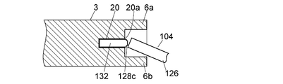
- FIGS. 1A to 1C An example of a sample-collecting chip dividing tool for assisting the cutting of each of the cutting portions 130, 131, 132 from the sample-collecting chip 102 will be described with reference to FIGS. 1A to 1C.
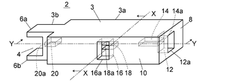
- the sample collection chip dividing instrument 2 of this embodiment includes a main body block 3, space portions 14, 18 and 20 provided inside the main body block 3, and a concave portion forming an enclosure provided on the outer surface of the main body block 3. 4, 12 and 16.
- the material of the main body block 3 may be any material as long as it is equivalent to or harder than the sampling chip 102, such as vinyl chloride or polypropylene.
- the main body block 3 includes a substantially rectangular parallelepiped portion 3a and a narrow portion 3b projecting from one end of the substantially rectangular parallelepiped portion 3a with a width dimension narrower than that of the substantially rectangular parallelepiped portion 3a.
- the side where the narrow portion 3b is provided in the main body block 3 is the distal end side, and the side opposite to the narrow portion 3b is the proximal end side.
- a recess 4 is provided on the front end surface of the narrow portion 3b of the main body block 3 over the entire width of the narrow portion 3b. Thereby, the cross-sectional shape of the narrow part 3b is U-shaped.
- An opening 20a leading to the space 20 is provided on the bottom surface of the recess 4 of the narrow portion 3b.
- a rectangular opening 12 a leading to the recess 12 is provided on the side surface 8 on the base end side of the main body block 3.
- An opening 14 a that leads to the space portion 14 is provided in the innermost surface of the recess 12.
- a rectangular opening 16 a leading to the recess 16 is provided on the side surface 10 orthogonal to the surface 8 of the main body block 3.
- An opening 18 a that communicates with the space 18 is provided on the innermost surface of the recess 16.
- the space portion 14 is for fitting a cutout portion 130 (see FIGS. 6A to 6C) located on the most proximal side of the sample collection chip 102.
- the space portion 14 is inserted into the cutout portion 130, and the tip body 104 of the sample collection tip 102 is folded at the position of the cutout slit 28a, thereby making the cutout portion 130 the sample collection tip 102.
- the height dimension of the recess 12 (the vertical dimension in FIGS. 1C and 2B) is such that the chip body 104 with the cutout 130 fitted in the space 14 can be folded at the position of the cutout slit 28a. Designed with various dimensions.
- the depth dimension (the dimension in the left-right direction in FIG. 1C) of the space portion 14 is designed to be slightly shorter (for example, about 1 mm) than the length dimension of the cutout portion 130.
- the cutout slit 28 a is disposed at a position slightly outside the edge of the opening 14 a of the space portion 14 and inside the recess 12.
- FIG. 2B when the main body chip 104 is folded at the position of the cut-off slit 28a, the inner peripheral surface of the recess 12 receives the liquid scattered from the fracture surface, and the liquid to the surroundings is received. Is prevented from scattering.
- the height dimension (the vertical dimension in FIG. 1C) of the space portion 14 is approximately the same as the thickness dimension of the cut-out portion 130, slightly larger than it, or slightly (for example, (0.1 mm) It should be designed to have a small dimension. Since the cutout part 130 is an unnecessary part that is not used for analysis, the cutout part 130 may remain accommodated in the main body block 3. Therefore, if the height dimension of the space portion 14 is designed to be slightly smaller than the thickness dimension of the cut portion 130, the cut portion 130 after being cut from the chip body 104 can be left in the main body block 3.
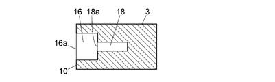
- the space 18 is used to fit the cut-out portion 131 (see FIGS. 6A to 6C) of the sample-collecting chip 102 after the cut-out portion 130 is cut out. .
- the space 18 is used to cut out the cut-out portion 131 from the sample-collecting tip 102 by fitting the cut-out portion 131 and folding the chip body 104 at the position of the cut-out slit 28b. Is done.
- the height of the recess 16 (the vertical dimension in FIGS. 1B and 3B) is such that the chip body 104 with the cutout 131 fitted in the space 16 can be folded at the position of the cutout slit 28b. Designed with various dimensions.
- the depth dimension (the dimension in the left-right direction in FIG. 1B) of the space 18 is designed to be slightly shorter (for example, about 1 mm) than the length dimension of the cutout 131.
- the height dimension of the space part 18 (the vertical dimension in FIG. 1B) is substantially the same as the thickness dimension of the cut part 131, or it can be removed so that the cut part 131 can be removed from the space part 18.
- the dimensions are designed to be slightly larger than the above.
- the space portion 20 is for fitting a cutout portion 132 (see FIGS. 6A to 6C) of the sample collection chip 102 after the cutout portion 131 is cut out.
- the space portion 20 is used to cut out the cutout portion 132 from the sample collection tip 102 by fitting the cutout portion 132 and folding the chip body 104 at the position of the cutout slit 28c. Is done.
- the height of the recess 4 (the vertical dimension in FIGS. 1C and 4B) is such that the chip body 104 with the cutout 132 fitted in the space 20 can be folded at the position of the cutout slit 28c. Designed with various dimensions.
- the depth dimension of the space part 20 (the dimension in the left-right direction in FIG. 1C) is designed to be slightly shorter (for example, about 1 mm) than the length dimension of the cutout part 132.
- the cutout slit 28 c is disposed at a position slightly outside the edge of the opening 20 a of the space portion 20 and inside the recess 4.
- FIG. 4B when the main body chip 104 is folded at the position of the cut slit 28c, the protrusions 6a and 6b sandwiching the recess 4 become wrinkles and the liquid scattered from the fracture surface The liquid is prevented from splashing around.
- the height dimension of the space part 20 (the vertical dimension in FIG. 1B) is substantially the same as the thickness dimension of the cut part 132 so that the cut-out part 132 can be removed from the space part 20 or
- the size is designed to be slightly larger than that.
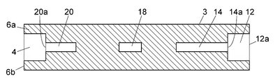
- the recesses 12, 16 and 4 are provided on the outer surface of the main body block 3, and the spaces 14, 18, and 20 are provided on the back side of the recesses, whereby the recess 12 , 16 and 4 are used as enclosures for receiving liquid scattered from the fracture surface of the main body chip 104.
- the enclosure for receiving the liquid scattered from the fracture surface of the main body chip 104 is not limited to such a recess.
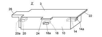
- the sample collection chip splitting device 2 ′ of the embodiment shown in FIG. 5 is provided with openings 14 a, 18 a and 20 a communicating with the space portions 14, 18 and 20 on the outer surface of the main body block 3.
- openings 14 a, 18 a and 20 a communicating with the space portions 14, 18 and 20 on the outer surface of the main body block 3.
- 22, 24 and 26 are provided.
- the flanges 22, 24 and 26 are provided only on one side of the openings 14a, 18a and 20a, but they may be provided so as to sandwich the openings 14a, 18a and 20a.
- sampling chip splitting device 2, 2 ′ of the embodiment described above is provided so that each space portion 14, 18 and 20 leads to a different side surface of the main body block 3, but the present invention is It is not limited to this, You may provide so that it may mutually lead to the same side surface.
Abstract
This device for dividing sample-capture chip comprises: a main block; a space provided within the main block and having an opening which opens out onto the outer surface of the main block, and which, through the hole, engages with the notch part of the sample-capture chip, thereby storing the same; and a surrounding part which is provided to the surroundings of the opening on the outside of the space, and which is for receiving samples that have been splashed from a broken part of the sample-capture chip divided in the proximity of the opening.
Description
本発明は、一端側に吸入口をもち、その吸入口から吸入された血液などの試料を保持しておくための流路を内部に有し、流路内に採取した試料の必要部分の一定量を分割可能に構成された試料採取チップを取り扱う器具であって、特にそのような試料採取チップを分割する際に利用される器具に関する。
The present invention has a suction port on one end side, and has a flow channel for holding a sample such as blood sucked from the suction port, and a necessary part of the sample collected in the flow channel is constant. The present invention relates to an instrument that handles a sampling chip configured to be divided into quantities, and particularly to an instrument that is used when dividing such a sampling chip.
従来の数mL以上入るような遠沈管に微量の血液を採取し、遠心分離処理をした後、血球成分が混じらないように上澄みの血漿成分のみの一定量をマイクロピペットなどで分取することは、試料量が微量であるほど困難になる。
After collecting a small amount of blood in a conventional centrifuge tube that can contain several mL or more and centrifuging it, it is not possible to separate a certain amount of the plasma component of the supernatant with a micropipette etc. The smaller the sample amount, the more difficult it becomes.
微量の血液試料に対して血漿成分を採取する器具として、両端が解放されたキャピラリからなる微量採血管が使用されている。微量採血管を使用した血漿成分の採取では、微量採血管に血液を吸引し、パテなどで先端を封じてから遠心分離を行う。その後、血漿部分と血球部分の界面近傍で採血管を折って切断し、血漿成分だけを別に用意した容積が定まった毛細管に移し替えることで取り出す。取り出した血漿成分を、適宜処理した後、TLC(薄層クロマトグラフ)、LC(液体クロマトグラフ)、LC/MS(液体クロマトグラフ・質量分析装置)、質量分析装置などで分析する。
As a device for collecting plasma components from a very small amount of blood sample, a small amount of blood collection tube consisting of a capillary with both ends opened is used. In collecting plasma components using a micro blood collection tube, blood is aspirated into the micro blood collection tube, and the tip is sealed with a putty or the like, followed by centrifugation. Thereafter, the blood collection tube is folded and cut in the vicinity of the interface between the plasma portion and the blood cell portion, and only the plasma component is taken out by being transferred to a capillary having a predetermined volume. The extracted plasma component is appropriately treated and then analyzed by TLC (thin layer chromatograph), LC (liquid chromatograph), LC / MS (liquid chromatograph / mass spectrometer), mass spectrometer and the like.
遠心分離された血球部分と血漿部分の間にある微量の白血球部分のみを採取することを目的とした遠心チューブも提案されている(特許文献1参照。)。その遠心チューブは、太径で大容量の上下2つの溜部の間に細径で小容量の溜部をもっている。下部の大容量溜部は有底で、上部の大容量溜部は開口により解放されている。その上部解放部から所定量を採血後、遠心分離すると白血球部分が小容量溜部にくるようになっている。遠心処理後に微細なガラス管(キャピラリ)を上部解放部より差し込み、小容量溜部にある白血球成分を採取する。
There has also been proposed a centrifuge tube intended to collect only a small amount of leukocyte portion between the centrifuged blood cell portion and plasma portion (see Patent Document 1). The centrifuge tube has a small-diameter and small-volume reservoir between two large and large reservoirs. The lower large-capacity reservoir is bottomed and the upper large-capacity reservoir is released by an opening. When a predetermined amount of blood is collected from the upper release portion and then centrifuged, the white blood cell portion comes to the small volume reservoir. After centrifuging, a fine glass tube (capillary) is inserted from the upper open part, and the white blood cell component in the small volume reservoir is collected.
ディスクに毛細管を含む幾つかの流路を設け、ディスクを遠心処理して血液の成分を分離し、試薬と反応させて検出する研究も盛んに行われている。それに用いる器具として、例えば、一体成形されたチャンバー、流路、リザーバ及び分析用セルを有するディスク形状部材からなる器具が提案されている(特許文献2参照。)。血液サンプルをその器具に導入し、遠心処理にかけて血球を血清から分離させ、次いで血清をいくつかの処理工程や検査にかける。
There are also many researches in which a disk is provided with several flow paths including capillaries, the disk is centrifuged to separate blood components, and reacted with a reagent for detection. As an instrument used therefor, for example, an instrument composed of a disk-shaped member having an integrally molded chamber, a channel, a reservoir, and an analysis cell has been proposed (see Patent Document 2). A blood sample is introduced into the instrument and centrifuged to separate the blood cells from the serum, which is then subjected to several processing steps and tests.
本発明らは、ごく微量の試料を精度よく採取することが可能な試料採取チップを提案し、実施もなされている(特許文献3参照。)。提案の試料採取チップは、内部に設けられた流路内に試料を採取した後、そのまま所定のホルダに保持させて遠心分離を行なうことができる。さらにこの試料採取チップは、分析者の手で折って流路の必要部分を切り取ることができるように外面にスリットが設けられており、複数部分に分割することができる。これにより、内部の流路内で分離した試料のうちの必要な一定量を容易に取り出すことができる。
The present inventors have proposed and implemented a sample collection chip capable of accurately collecting a very small amount of sample (see Patent Document 3). In the proposed sample collection chip, a sample can be collected in a flow path provided therein, and then held in a predetermined holder as it is to perform centrifugation. Further, this sample collection chip is provided with a slit on the outer surface so that it can be folded by an analyst's hand and cut off a necessary part of the flow path, and can be divided into a plurality of parts. Thereby, a necessary fixed amount of the samples separated in the internal flow path can be easily taken out.
ここで、試料採取チップを分割する際、スリット部分が破断したときの衝撃により、流路内の試料が外部へ飛散する可能性がある。特に生体試料を取り扱う場合は、バイオハザードの可能性もあるため、飛散物には注意する必要がある。また、複数部分に分割する場合、取り出したい部分の長さが短いとその部分の切取りが難しいという問題がある。
Here, when the sample collection chip is divided, the sample in the flow path may be scattered to the outside due to an impact when the slit portion is broken. In particular, when handling a biological sample, there is a possibility of a biohazard, so it is necessary to pay attention to scattered matter. Moreover, when dividing | segmenting into several parts, there exists a problem that it is difficult to cut out the part if the length of the part to take out is short.
そこで、本発明は、内部の試料の飛散を防止しながら試料採取チップの分割を容易に行なうことができる器具を提供することを目的とするものである。
Therefore, an object of the present invention is to provide an instrument that can easily divide a sampling chip while preventing scattering of an internal sample.
本発明に係る試料採取チップ分割用器具は、試料採取用の流路を内部に有するとともに、前記流路の一部を切り取るために外面に設けられた切取り用スリットの位置で切取り可能な少なくとも1つの切取り部を有し、前記切取り用スリットの位置で一定の折り曲げ方向へ折ることによって前記切取り部を切り取ることができる試料採取チップの前記切取り部を切り取るための試料採取チップ分割用器具である。当該試料採取チップ分割用器具は、本体ブロックと、前記本体ブロックの内部に設けられているとともに前記本体ブロックの外面に通じる開口をもち、その開口を介して前記試料採取チップの前記切取り部を嵌め込んで収容する空間部と、前記空間部の外側で前記開口の周囲に設けられ、前記開口の近傍で分割された前記試料採取チップの破断部から飛散する試料を受けるための囲い部と、を備えている。
The sample collection chip dividing instrument according to the present invention has a sample collection channel inside, and at least one that can be cut out at a position of a cut-out slit provided on the outer surface to cut out a part of the channel. The sample collection tip splitting device for cutting out the cutout portion of the sample collection tip that has two cutout portions and can cut out the cutout portion by folding the cutout portion at a position of the cutout slit. The sample collecting chip dividing instrument has a main body block, an opening provided in the main body block and leading to the outer surface of the main body block, and the cutout portion of the sample collecting chip is fitted through the opening. A space part for receiving the sample scattered from the broken part of the sample-collecting chip provided around the opening outside the space part and divided in the vicinity of the opening; I have.
前記空間部は、前記切取り部を当該空間部の奥まで差し込んだときに、その切取り部を切り取るために前記試料採取チップの外面に設けられた前記切取り用スリットが当該空間部の前記開口の位置又はそれよりも僅かに前記空間部の外側の位置にくるように、その奥行寸法が設定されていることが好ましい。そうすれば、切取り部を空間部の奥まで差し込むことで、その切取り部を切り取るための切取り用スリットが必ず空間部の開口付近に位置するようになる。これにより、試料採取チップを折り曲げようとしたときに開口の縁の角部が切取り用スリット付近に接触し、切取り用スリットが設けられている位置に応力が集中して作用するため、その切取り用スリットが設けられている位置で試料採取チップが破断しやすくなる。したがって、目的の切取り部を確実に切り取ることができる。
The space portion has a position where the opening of the space portion is formed by the slit for cutting provided on the outer surface of the sample-collecting chip in order to cut the cut portion when the cut portion is inserted into the space portion. Or it is preferable that the depth dimension is set so that it may come to the position of the outer side of the said space part slightly more than it. By doing so, by inserting the cutout part to the back of the space part, the cutout slit for cutting out the cutout part is always located near the opening of the space part. As a result, when the sample collection tip is bent, the corner of the edge of the opening comes into contact with the vicinity of the cutting slit, and stress concentrates on the position where the cutting slit is provided. The sampling tip is easily broken at the position where the slit is provided. Therefore, the target cut-out part can be cut out reliably.
ところで、空間部の厚み寸法はその空間部に嵌め込まれる切取り部の厚み寸法と略同一であるかそれよりも大きい必要があるが、空間部の厚み寸法が試料採取チップの切取り部の厚み寸法よりも大きすぎると、試料採取チップを折り曲げようとしたときに狙った位置に応力を作用させにくくなる。したがって、空間部の厚み寸法は最大でもその空間部に嵌め込まれる切取り部の厚み寸法よりも僅かに大きい程度であることが好ましい。「僅かに大きい」とは、空間部の内壁とその空間部に嵌め込まれた切取り部との間に生じる隙間が、例えば2mm以下であることを意味する。
By the way, the thickness dimension of the space portion needs to be substantially the same as or larger than the thickness dimension of the cutout portion fitted into the space portion, but the thickness dimension of the space portion is larger than the thickness dimension of the cutout portion of the sampling chip. If it is too large, it becomes difficult to apply a stress to the target position when the sample collection tip is bent. Therefore, it is preferable that the thickness dimension of the space portion is at most slightly larger than the thickness dimension of the cutout portion fitted into the space portion. “Slightly large” means that a gap generated between the inner wall of the space portion and the cut portion fitted in the space portion is, for example, 2 mm or less.
本発明の好ましい実施形態では、前記囲い部が、前記本体ブロックの外面に設けられ前記空間部へ通じ、前記切取り部が前記空間部に嵌め込まれた状態の前記試料採取チップを前記折り曲げ方向へ折ることができる寸法をもつ凹部である。このような形態にすれば、簡単な構成によって囲い部を設けることができるので、本発明の試料採取チップ分割用器具を容易にかつ安価に作成することができる。
In a preferred embodiment of the present invention, the enclosure portion is provided on the outer surface of the main body block, communicates with the space portion, and the sampling chip with the cutout portion fitted in the space portion is folded in the bending direction. It is a recess having a dimension that can be applied. With such a configuration, the enclosure can be provided with a simple configuration, and therefore the sample collection chip dividing instrument of the present invention can be easily and inexpensively produced.
本発明の試料採取チップ分割用器具は、試料採取チップが複数の前記切取り部を有するものである場合にも適用することができる。試料採取チップが複数の切取り部を有する場合には、本体ブロックに、前記試料採取チップの前記切取り部のそれぞれに個別に対応した複数の前記空間部と前記囲い部が設けられている。
The sample collection tip splitting instrument of the present invention can also be applied when the sample collection tip has a plurality of the cutout portions. When the sample collection tip has a plurality of cutout portions, the main body block is provided with a plurality of the space portions and the surrounding portions individually corresponding to the cutout portions of the sample collection tip.
上記の場合、各空間部の開口は本体ブロックの互いに異なる側面に通じていることが好ましい。「各空間部の開口が本体ブロックの互いに異なる側面に通じている」とは、本体ブロックの複数の面に試料採取チップの各切取り部を挿し込むための開口が設けられていることを意味する。試料採取チップの各切取り部を挿し込むための開口を本体ブロックの互いに異なる側面に設けることで、作業者が切取り部を切り取る際に切取り部を挿し込む位置(開口)を間違えにくくなる。
In the above case, it is preferable that the opening of each space portion leads to different side surfaces of the main body block. “The opening of each space portion leads to different side surfaces of the main body block” means that openings for inserting the respective cutout portions of the sample collection chip are provided on a plurality of surfaces of the main body block. . By providing openings for inserting the respective cutout portions of the sample collection chip on different side surfaces of the main body block, the position (opening) into which the cutout portion is inserted when the operator cuts out the cutout portion is less likely to be mistaken.
本発明の試料採取チップ分割用器具では、本体ブロックと、本体ブロックの内部に設けられているとともに当該本体ブロックの外面に通じる開口をもち、その開口を介して試料採取チップの切取り部を嵌め込んで収容する空間部と、を備えているので、試料採取チップの切取り部を本体ブロックの空間部へ嵌め込んで試料採取チップを折るように試料採取チップと本体ブロックに力を加えるだけで、試料採取チップから切取り部を切り取ることができる。これにより、試料採取チップからの切取り部の切取りが容易である。さらに、空間部の外側で開口の周囲に、開口の近傍で分割された試料採取チップの破断部から飛散する試料を受けるための囲い部が設けられているので、試料採取チップから切取り部を切り取る際の試料の周囲への飛散を囲い部によって食い止め、バイオハザード等の問題の発生を防止することができる。
In the sample collection chip splitting instrument of the present invention, the main body block has an opening that is provided inside the main body block and communicates with the outer surface of the main body block, and a cutout portion of the sample collection chip is fitted through the opening. A space to be accommodated in the sample block, so that the sample collection chip and the main body block can be folded by fitting the cutout portion of the sample collection chip into the space portion of the main body block and folding the sample collection chip. A cut-out portion can be cut from the sampling tip. Thereby, it is easy to cut the cut portion from the sample collection tip. In addition, an enclosure is provided around the opening outside the space to receive the sample scattered from the fractured portion of the sample-collecting chip divided in the vicinity of the opening, so that the cut-out part is cut out from the sample-collecting chip. It is possible to prevent the occurrence of problems such as biohazard by stopping the scattering of the sample around the sample by the surrounding portion.
以下、試料採取チップ分割用器具の一実施例について図面を参照しながら説明する。
Hereinafter, an embodiment of the sampling chip dividing instrument will be described with reference to the drawings.
まず、試料採取チップ分割用器具の対象となる試料採取チップの一例について図6A~図6Cを用いて説明する。
First, an example of a sample collection chip that is a target of the sample collection chip dividing instrument will be described with reference to FIGS. 6A to 6C.
試料採取チップ102はチップ本体104を備え、チップ本体104は下基板106と上基板108から構成されている。下基板106と上基板108は接合により一体化されてチップ本体104を構成している。上基板108の接合面には試料採取用の流路110が形成され、下基板106と上基板108が接合されていることにより流路110がチップ本体104内に配置されている。
The sample collection chip 102 includes a chip body 104, and the chip body 104 includes a lower substrate 106 and an upper substrate 108. The lower substrate 106 and the upper substrate 108 are integrated by bonding to constitute the chip body 104. A sample-collecting flow path 110 is formed on the bonding surface of the upper substrate 108, and the flow path 110 is arranged in the chip body 104 by bonding the lower substrate 106 and the upper substrate 108.
チップ本体104は基端112と先端114をもっている。この試料採取チップ102は試料を吸引した後に遠心分離処理を施すものであり、その際に遠心力が基端112から先端114の方向に作用するように、この試料採取チップ102が遠心分離機に装着される。チップ本体104の基端、先端という呼び方は、その遠心力の方向を基準に決めている。
The chip body 104 has a proximal end 112 and a distal end 114. The sample collection chip 102 performs a centrifugal separation process after sucking the sample, and the sample collection chip 102 is applied to the centrifuge so that the centrifugal force acts in the direction from the base end 112 to the tip end 114 at that time. Installed. The term “base end” or “tip end” of the chip body 104 is determined based on the direction of the centrifugal force.
チップ本体104は基端側に試料吸込口116をもっている。試料吸込口116はチップ本体104の基端112に設けられた凹部118内に通じる開口として設けられている。その凹部118は、試料採取の際に先端114を血液などの試料に接触させたときに試料が試料吸込口116から吸引されるのを容易にするためのものである。
The chip body 104 has a sample suction port 116 on the proximal end side. The sample suction port 116 is provided as an opening that communicates with a recess 118 provided at the base end 112 of the chip body 104. The concave portion 118 is for facilitating the suction of the sample from the sample suction port 116 when the tip 114 is brought into contact with a sample such as blood during sample collection.
流路110は毛細管現象により試料を吸引できる細さをもっている。流路110はチップ本体104内の先端側の連結部120でつながり、先端側から基端側に延びる2本の流路部分110a、110bをもっている。一方の流路部分110aは導入流路110cをもち、その導入流路110cが試料吸入口16に通じている。他方の流路部分110bは基端112に至らない位置で終端している。
The flow path 110 has such a thickness that can suck a sample by capillary action. The flow path 110 is connected by a connecting portion 120 on the distal end side in the chip body 104, and has two flow path portions 110a and 110b extending from the distal end side to the proximal end side. One channel portion 110 a has an introduction channel 110 c, and the introduction channel 110 c communicates with the sample suction port 16. The other flow path portion 110 b terminates at a position that does not reach the base end 112.
流路部分110bの終端部に液溜まり空間110dが設けられている。液溜まり空間110dは、毛細管現象によって液を吸引しないような大きさの断面積を少なくともその入口部分(液溜まり空間10dの先端側端部)にもち、空気穴122はこの液溜まり空間110dの基端側端部に通じている。液溜まり空間110dは、流路部分110aの導入流路110cのうち空気穴122よりも基端側(図において上側)にある部分の内部容量以上の内部容量を有する。
A liquid pool space 110d is provided at the end of the flow path portion 110b. The liquid reservoir space 110d has at least a cross-sectional area large enough not to suck liquid by capillary action, and the air hole 122 is a base of the liquid reservoir space 110d. It leads to the end side end. The liquid storage space 110d has an internal capacity that is equal to or greater than the internal capacity of the portion of the introduction flow path 110c of the flow path portion 110a that is on the base end side (upper side in the drawing) of the air hole 122.
液溜まり空間110dの入口部の断面積は、例えば流路部分110bの他の部分の断面積の2倍以上である。液溜まり空間10dの入口部の断面寸法の一例は、幅が3mm、深さが1.5mm程度である。
The cross-sectional area of the inlet of the liquid pool space 110d is, for example, twice or more the cross-sectional area of the other part of the flow path part 110b. An example of the cross-sectional dimension of the inlet portion of the liquid pool space 10d is about 3 mm in width and about 1.5 mm in depth.
流路部分110bの終端部にかかる液溜まり空間110dを設けることの利点として、次のことが挙げられる。
Advantages of providing the liquid pool space 110d at the end of the flow path portion 110b include the following.
まず、液溜まり空間110dは毛細管現象によって試料を吸引しないため、試料吸入口116から吸引された試料は、空気穴122の位置まで達することなく、液溜まり空間110dの入口部分で停止することとなる。これにより、抽出部110内に採取される試料の量を増やすことなく、流路部分110a,110b内への試料採取量を確保することができる。
First, since the liquid pool space 110d does not suck the sample due to capillary action, the sample sucked from the sample suction port 116 does not reach the position of the air hole 122 and stops at the inlet portion of the liquid pool space 110d. . Thereby, the sample collection amount in the flow path portions 110a and 110b can be ensured without increasing the amount of the sample collected in the extraction unit 110.
さらに、試料吸入口116から吸引された試料は液溜まり空間110dの入口部分で停止するため、遠心分離が施される前では、液溜まり空間110d内に試料がない状態となる。なお,液溜まり空間110dの内面を疎水性にすることで、液溜まり空間110dの入口部分において、より確実に試料を停止させることができる。この状態で遠心分離が施されると、試料が平衡状態となることによって余剰となった試料は液溜まり空間110d内に貯留される。液溜まり空間110dの内部容量は、流路部分110aの導入流路110cのうち空気穴122よりも基端側(図において上側)にある部分の内部容量以上であるため、余剰となった試料のすべてが液溜まり空間110d内に貯留されることとなる。これにより、余剰となった試料が流路部分110bから溢れ出て空気穴122から排出されることを抑制することができる。
Furthermore, since the sample sucked from the sample suction port 116 stops at the inlet portion of the liquid pool space 110d, there is no sample in the liquid pool space 110d before centrifugation. In addition, by making the inner surface of the liquid pool space 110d hydrophobic, the sample can be stopped more reliably at the inlet portion of the liquid pool space 110d. When the centrifugal separation is performed in this state, the surplus sample due to the equilibrium of the sample is stored in the liquid pool space 110d. Since the internal volume of the liquid reservoir space 110d is equal to or greater than the internal volume of the portion of the introduction flow path 110c of the flow path portion 110a that is on the base end side (upper side in the drawing) of the air hole 122, All are stored in the liquid pool space 110d. Thereby, it can suppress that the sample which became surplus overflows from the flow-path part 110b, and is discharged | emitted from the air hole 122. FIG.
この実施例の試料採取チップ102は、基端側に採取部124、先端側に幅広部126が設けられている。採取部124の幅寸法及び厚み寸法は幅広部126の幅寸法と厚み寸法よりも小さくなっている。採取部124の上面と下面のそれぞれに、採取部124(流路110)が延びる方向と直交する3本の切取り用スリット128a、128b及び128cが設けられている。切取り用スリット128cは採取部124と幅広部126との境界部分に設けられている。切取り用スリット128aは空気穴122よりも先端側の位置に設けられ、切取り用スリット128bは切取り用スリット128aと128cとの間の位置に設けられている。
The sample collection chip 102 of this embodiment is provided with a collection portion 124 on the proximal end side and a wide portion 126 on the distal end side. The width dimension and the thickness dimension of the sampling part 124 are smaller than the width dimension and the thickness dimension of the wide part 126. Three cutting slits 128a, 128b, and 128c that are orthogonal to the direction in which the sampling portion 124 (channel 110) extends are provided on the upper surface and the lower surface of the sampling portion 124, respectively. The cutting slit 128c is provided at the boundary between the sampling portion 124 and the wide portion 126. The cut slit 128a is provided at a position on the tip side of the air hole 122, and the cut slit 128b is provided at a position between the cut slits 128a and 128c.
採取部124の3箇所の位置に切取り用スリット128a、128b及び128cが設けられていることにより、採取部124を3つの切取り部130、131及び132に分割することができる。この試料採取チップ102は、切取り用スリット126aの位置で折るように応力を加えれば、切取り部130を切り取ることができ、さらに切取り用スリット126bの位置で折るように応力を加えれば、切取り部131を切り取ることができ、さらに切取り用スリット126cの位置で折るように応力を加えれば、切取り部132を切り取ることができる。
Since the cutting slits 128a, 128b, and 128c are provided at three positions of the sampling unit 124, the sampling unit 124 can be divided into three cutting units 130, 131, and 132. If stress is applied to the sampling chip 102 so as to be folded at the position of the cut slit 126a, the cut portion 130 can be cut, and if stress is applied so as to be folded at the position of the cut slit 126b, the cut portion 131 is obtained. If a stress is applied so as to be folded at the position of the cut slit 126c, the cut portion 132 can be cut.
切取り部131及び132には2本の流路部分110a,110bが含まれており、切取り部131、132を切り取ることによって、これらの切取り部131、132の流路部分110a、110b内に保持された一定量の試料を容易に取り出すことができる。
The cutout portions 131 and 132 include two flow passage portions 110a and 110b. By cutting the cutout portions 131 and 132, the cutout portions 131 and 132 are held in the flow passage portions 110a and 110b of the cutout portions 131 and 132. A certain amount of sample can be easily taken out.
採取部124において切取り部131及び132が配置されている位置は基端部側にあるので、採取した試料に遠心分離処理を施したとき、切取り部131及び132には遠心分離された比重の小さい方の成分が位置する。例えば、試料として血液を採取し、この試料採取チップ102の基端側から先端側が遠心力の作用する方向になるように遠心分離処理を施したとき、切取り部131及び132には血漿成分又は血清成分がくるように、流路110における切取り部131及び132の位置が設定されている。
Since the position where the cut-out parts 131 and 132 are arranged in the collection part 124 is on the base end side, when the collected sample is subjected to a centrifugal separation process, the cut-out parts 131 and 132 have a low specific gravity that is centrifuged. The other component is located. For example, when blood is collected as a sample and subjected to a centrifugal separation process so that the distal end side of the sample collection chip 102 is in the direction in which the centrifugal force acts, the cut portions 131 and 132 have plasma components or serum. The positions of the cutout portions 131 and 132 in the flow path 110 are set so that the components come.
幅広部126はこの試料採取チップに採取された試料の名称や番号などの識別情報を記入したり、その識別情報を記入したラベルを貼りつけたりできる程度の大きさをもっている。幅広部126はまた、この試料採取チップをもつ際の把持部としても使用できる。
The wide part 126 has such a size that identification information such as the name and number of the sample collected on the sample collection chip can be entered and a label filled with the identification information can be attached. The wide portion 126 can also be used as a gripping portion when the sample collection tip is held.
試料採取チップ102は例えば樹脂材料により構成されている。その樹脂材料は特に限定されるものではないが、例えばCOP(シクロオレフィンポリマー)、PMMA(ポリメタクリル酸メチル樹脂)、PP(ポリプロピレン樹脂)、PC(ポリカーボネート樹脂)、PVA(ポリビニルアルコール)などを用いることができる。
The sample collection chip 102 is made of, for example, a resin material. The resin material is not particularly limited. For example, COP (cycloolefin polymer), PMMA (polymethyl methacrylate resin), PP (polypropylene resin), PC (polycarbonate resin), PVA (polyvinyl alcohol), or the like is used. be able to.
流路110は試料吸入口116から毛細管現象により液体試料を吸入するものであるため、流路110の断面積は毛細管現象を起こす細さであるだけでなく、試料が血液又は水溶液である場合には流路110の内面が親水性である必要がある。上に例示した樹脂材料は疎水性であるので、流路110内面と試料吸入口116は親水性になるように処理されていることが好ましい。
Since the channel 110 sucks a liquid sample from the sample inlet 116 by capillary action, the cross-sectional area of the channel 110 is not only thin enough to cause capillary action, but also when the sample is blood or an aqueous solution. Requires that the inner surface of the channel 110 be hydrophilic. Since the resin material exemplified above is hydrophobic, the inner surface of the flow path 110 and the sample suction port 116 are preferably treated so as to be hydrophilic.
試料が血液である場合、血液を検体から直接吸引し、遠心分離により切取り部130に血漿を採取するために、流路110の内面には血液の凝固を防止する抗凝固剤が設けられていることが好ましい。抗凝固剤は流路110の内面に親水性ポリマーをコーティングした後、その上からコーティングしても良い。
When the sample is blood, an anticoagulant that prevents blood coagulation is provided on the inner surface of the flow path 110 in order to suck blood directly from the specimen and collect plasma in the cutout portion 130 by centrifugation. It is preferable. The anticoagulant may be coated on the inner surface of the flow path 110 after coating with a hydrophilic polymer.
この試料採取チップ102は、遠心分離後に切取り部131(及び132)を分析に供するために、切取り部131(及び132)がチップ本体104から切り離され、個別の切取り部131、132となる。試料採取チップ102から切取り部130、131及び132を切り取っていくには、チップ本体104を切取り用スリット128a、128b及び128cの位置で順に折っていく。このようにして、1つのチップ本体104から2つの分析用試料を得ることができる。一般に、最も基端側の切取り部130は不要な部分となるため、廃棄される。
In this sample collection chip 102, the cut-out part 131 (and 132) is separated from the chip body 104 and becomes separate cut-out parts 131 and 132 in order to use the cut-out part 131 (and 132) for analysis after centrifugation. In order to cut the cut portions 130, 131, and 132 from the sample collection tip 102, the tip body 104 is sequentially folded at the positions of the cut slits 128a, 128b, and 128c. In this way, two samples for analysis can be obtained from one chip body 104. Generally, the most proximal-side cutout 130 is an unnecessary part and is discarded.
次に、試料採取チップ102からの各切取り部130、131、132の切取りを補助するための試料採取チップ分割用器具の一実施例について、図1A-図1Cを用いて説明する。
Next, an example of a sample-collecting chip dividing tool for assisting the cutting of each of the cutting portions 130, 131, 132 from the sample-collecting chip 102 will be described with reference to FIGS. 1A to 1C.
この実施例の試料採取チップ分割用器具2は、本体ブロック3と、本体ブロック3の内部に設けられた空間部14、18及び20と、本体ブロック3の外面に設けられた囲い部をなす凹部4、12及び16と、を備えている。本体ブロック3の材質は、例えば塩化ビニルやポリプロピレンなど、試料採取チップ102と同等かそれよりも硬いものであればいかなるものであってもよい。
The sample collection chip dividing instrument 2 of this embodiment includes a main body block 3, space portions 14, 18 and 20 provided inside the main body block 3, and a concave portion forming an enclosure provided on the outer surface of the main body block 3. 4, 12 and 16. The material of the main body block 3 may be any material as long as it is equivalent to or harder than the sampling chip 102, such as vinyl chloride or polypropylene.
本体ブロック3は、略直方体部分3aと略直方体部分3aよりも細い幅寸法で略直方体部分3aの一端から突起した狭小部3bからなる。以下の説明では、本体ブロック3において狭小部3bが設けられている側を先端側、狭小部3bとは反対側を基端側とする。本体ブロック3の狭小部3bの先端面に凹部4が狭小部3bの全幅にわたって設けられている。これにより、狭小部3bの断面形状がU字型になっている。狭小部3bの凹部4の底面に空間部20へ通じる開口20aが設けられている。
The main body block 3 includes a substantially rectangular parallelepiped portion 3a and a narrow portion 3b projecting from one end of the substantially rectangular parallelepiped portion 3a with a width dimension narrower than that of the substantially rectangular parallelepiped portion 3a. In the following description, the side where the narrow portion 3b is provided in the main body block 3 is the distal end side, and the side opposite to the narrow portion 3b is the proximal end side. A recess 4 is provided on the front end surface of the narrow portion 3b of the main body block 3 over the entire width of the narrow portion 3b. Thereby, the cross-sectional shape of the narrow part 3b is U-shaped. An opening 20a leading to the space 20 is provided on the bottom surface of the recess 4 of the narrow portion 3b.
本体ブロック3の基端側の側面8に凹部12へ通じる矩形の開口12aが設けられている。凹部12の最奥面に空間部14へ通じる開口14aが設けられている。本体ブロック3の面8と直交する側面10に凹部16へ通じる矩形の開口16aが設けられている。凹部16の最奥面に空間部18へ通じる開口18aが設けられている。
A rectangular opening 12 a leading to the recess 12 is provided on the side surface 8 on the base end side of the main body block 3. An opening 14 a that leads to the space portion 14 is provided in the innermost surface of the recess 12. A rectangular opening 16 a leading to the recess 16 is provided on the side surface 10 orthogonal to the surface 8 of the main body block 3. An opening 18 a that communicates with the space 18 is provided on the innermost surface of the recess 16.
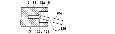
空間部14は、図2Aに示されているように、試料採取チップ102の最も基端側に位置する切取り部130(図6A~図6Cを参照。)を嵌め込むためのものである。図2Bに示されているように、空間部14は、切取り部130を嵌め込んで試料採取チップ102のチップ本体104を切取り用スリット28aの位置で折ることによって、切取り部130を試料採取チップ102から切り取るために利用される。凹部12の高さ寸法(図1C及び図2Bにおいて上下方向の寸法)は、空間部14に切取り部130を嵌め込んだ状態のチップ本体104を、切取り用スリット28aの位置で折ることができるような寸法に設計されている。
As shown in FIG. 2A, the space portion 14 is for fitting a cutout portion 130 (see FIGS. 6A to 6C) located on the most proximal side of the sample collection chip 102. As shown in FIG. 2B, the space portion 14 is inserted into the cutout portion 130, and the tip body 104 of the sample collection tip 102 is folded at the position of the cutout slit 28a, thereby making the cutout portion 130 the sample collection tip 102. Used to cut from. The height dimension of the recess 12 (the vertical dimension in FIGS. 1C and 2B) is such that the chip body 104 with the cutout 130 fitted in the space 14 can be folded at the position of the cutout slit 28a. Designed with various dimensions.
空間部14の奥行寸法(図1Cにおいて左右方向の寸法)は、切取り部130の長さ寸法よりも僅かに(例えば1mm程度)短く設計されている。これにより、切取り部130が空間部14の奥まで嵌め込まれたときに、切取り用スリット28aが空間部14の開口14aの縁よりも僅かに外側で凹部12の内側の位置に配置される。これにより、図2Bに示されているように、切取り用スリット28aの位置で本体チップ104を折ったときに、凹部12の内周面がその破断面から飛散する液を受け、周囲への液の飛散が防止される。
The depth dimension (the dimension in the left-right direction in FIG. 1C) of the space portion 14 is designed to be slightly shorter (for example, about 1 mm) than the length dimension of the cutout portion 130. Thus, when the cutout portion 130 is fitted to the back of the space portion 14, the cutout slit 28 a is disposed at a position slightly outside the edge of the opening 14 a of the space portion 14 and inside the recess 12. As a result, as shown in FIG. 2B, when the main body chip 104 is folded at the position of the cut-off slit 28a, the inner peripheral surface of the recess 12 receives the liquid scattered from the fracture surface, and the liquid to the surroundings is received. Is prevented from scattering.
空間部14の高さ寸法(図1Cにおいて上下方向の寸法)は、切取り部130の厚み寸法と略同一の寸法か、それよりも僅かに大きい程度の寸法か、又はそれよりも僅かに(例えば0.1mm)小さい程度の寸法に設計されていればよい。切取り部130は分析に供しない不要な部分であるから、本体ブロック3の内部に収容されたままになってもよい。そのため、空間部14の高さ寸法を切取り部130の厚み寸法よりも僅かに小さく設計すれば、チップ本体104から切り取った後の切取り部130を本体ブロック3内に残すことができる。
The height dimension (the vertical dimension in FIG. 1C) of the space portion 14 is approximately the same as the thickness dimension of the cut-out portion 130, slightly larger than it, or slightly (for example, (0.1 mm) It should be designed to have a small dimension. Since the cutout part 130 is an unnecessary part that is not used for analysis, the cutout part 130 may remain accommodated in the main body block 3. Therefore, if the height dimension of the space portion 14 is designed to be slightly smaller than the thickness dimension of the cut portion 130, the cut portion 130 after being cut from the chip body 104 can be left in the main body block 3.
空間部18は、図3Aに示されているように、切取り部130が切り取られた後の試料採取チップ102の切取り部131(図6A~図6Cを参照。)を嵌め込むためのものである。図3Bに示されているように、空間部18は、切取り部131を嵌め込んでチップ本体104を切取り用スリット28bの位置で折ることによって、切取り部131を試料採取チップ102から切り取るために利用される。凹部16の高さ寸法(図1B及び図3Bにおいて上下方向の寸法)は、空間部16に切取り部131を嵌め込んだ状態のチップ本体104を、切取り用スリット28bの位置で折ることができるような寸法に設計されている。
As shown in FIG. 3A, the space 18 is used to fit the cut-out portion 131 (see FIGS. 6A to 6C) of the sample-collecting chip 102 after the cut-out portion 130 is cut out. . As shown in FIG. 3B, the space 18 is used to cut out the cut-out portion 131 from the sample-collecting tip 102 by fitting the cut-out portion 131 and folding the chip body 104 at the position of the cut-out slit 28b. Is done. The height of the recess 16 (the vertical dimension in FIGS. 1B and 3B) is such that the chip body 104 with the cutout 131 fitted in the space 16 can be folded at the position of the cutout slit 28b. Designed with various dimensions.
空間部18の奥行寸法(図1Bにおいて左右方向の寸法)は、切取り部131の長さ寸法よりも僅かに(例えば1mm程度)短く設計されている。これにより、切取り部131が空間部18の奥まで嵌め込まれたときに、切取り用スリット28bが空間部18の開口18aの縁よりも僅かに外側で凹部16の内側の位置に配置される。これにより、図3Bに示されているように、切取り用スリット28bの位置で本体チップ104を折ったときに、凹部16の内周面がその破断面から飛散する液を受け、周囲への液の飛散が防止される。
The depth dimension (the dimension in the left-right direction in FIG. 1B) of the space 18 is designed to be slightly shorter (for example, about 1 mm) than the length dimension of the cutout 131. Thereby, when the cutout portion 131 is fitted to the back of the space portion 18, the cutout slit 28 b is disposed at a position slightly outside the edge of the opening 18 a of the space portion 18 and inside the recess 16. As a result, as shown in FIG. 3B, when the main body chip 104 is folded at the position of the cut-off slit 28b, the inner peripheral surface of the recess 16 receives the liquid scattered from the fracture surface, and the liquid to the surroundings is received. Is prevented from scattering.
切り取られた切取り部131を空間部18から取り出すことができるように、空間部18の高さ寸法(図1Bにおいて上下方向の寸法)が切取り部131の厚み寸法と略同一の寸法か、又はそれよりも僅かに大きい程度の寸法に設計されている。
The height dimension of the space part 18 (the vertical dimension in FIG. 1B) is substantially the same as the thickness dimension of the cut part 131, or it can be removed so that the cut part 131 can be removed from the space part 18. The dimensions are designed to be slightly larger than the above.
空間部20は、図4Aに示されているように、切取り部131が切り取られた後の試料採取チップ102の切取り部132(図6A~図6Cを参照。)を嵌め込むためのものである。図4Bに示されているように、空間部20は、切取り部132を嵌め込んでチップ本体104を切取り用スリット28cの位置で折ることによって、切取り部132を試料採取チップ102から切り取るために利用される。凹部4の高さ寸法(図1C及び図4Bにおいて上下方向の寸法)は、空間部20に切取り部132を嵌め込んだ状態のチップ本体104を、切取り用スリット28cの位置で折ることができるような寸法に設計されている。
As shown in FIG. 4A, the space portion 20 is for fitting a cutout portion 132 (see FIGS. 6A to 6C) of the sample collection chip 102 after the cutout portion 131 is cut out. . As shown in FIG. 4B, the space portion 20 is used to cut out the cutout portion 132 from the sample collection tip 102 by fitting the cutout portion 132 and folding the chip body 104 at the position of the cutout slit 28c. Is done. The height of the recess 4 (the vertical dimension in FIGS. 1C and 4B) is such that the chip body 104 with the cutout 132 fitted in the space 20 can be folded at the position of the cutout slit 28c. Designed with various dimensions.
空間部20の奥行寸法(図1Cにおいて左右方向の寸法)は、切取り部132の長さ寸法よりも僅かに(例えば1mm程度)短く設計されている。これにより、切取り部132が空間部20の奥まで嵌め込まれたときに、切取り用スリット28cが空間部20の開口20aの縁よりも僅かに外側で凹部4の内側の位置に配置される。これにより、図4Bに示されているように、切取り用スリット28cの位置で本体チップ104を折ったときに、凹部4を挟む突起6a、6bが庇となってその破断面から飛散する液を受け、周囲への液の飛散が防止される。
The depth dimension of the space part 20 (the dimension in the left-right direction in FIG. 1C) is designed to be slightly shorter (for example, about 1 mm) than the length dimension of the cutout part 132. Thus, when the cutout portion 132 is fitted to the back of the space portion 20, the cutout slit 28 c is disposed at a position slightly outside the edge of the opening 20 a of the space portion 20 and inside the recess 4. As a result, as shown in FIG. 4B, when the main body chip 104 is folded at the position of the cut slit 28c, the protrusions 6a and 6b sandwiching the recess 4 become wrinkles and the liquid scattered from the fracture surface The liquid is prevented from splashing around.
切り取られた切取り部132を空間部20から取り出すことができるように、空間部20の高さ寸法(図1Bにおいて上下方向の寸法)は、切取り部132の厚み寸法と略同一の寸法か、又はそれよりも僅かに大きい程度の寸法に設計されている。
The height dimension of the space part 20 (the vertical dimension in FIG. 1B) is substantially the same as the thickness dimension of the cut part 132 so that the cut-out part 132 can be removed from the space part 20 or The size is designed to be slightly larger than that.
上記実施例の試料採取チップ分割用器具2では、本体ブロック3の外面に凹部12、16及び4を設け、それらの凹部よりも奥側に空間部14、18及び20を設けることで、凹部12、16及び4の内側面を本体チップ104の破断面から飛散する液を受けるための囲い部として利用している。
In the sampling chip dividing instrument 2 of the above embodiment, the recesses 12, 16 and 4 are provided on the outer surface of the main body block 3, and the spaces 14, 18, and 20 are provided on the back side of the recesses, whereby the recess 12 , 16 and 4 are used as enclosures for receiving liquid scattered from the fracture surface of the main body chip 104.
しかし、本発明において、本体チップ104の破断面から飛散する液を受けるための囲い部は、このような凹部に限定されない。
However, in the present invention, the enclosure for receiving the liquid scattered from the fracture surface of themain body chip 104 is not limited to such a recess.
However, in the present invention, the enclosure for receiving the liquid scattered from the fracture surface of the
例えば、図5に示す実施例の試料採取チップ分割用器具2'は、本体ブロック3の外面に各空間部14、18及び20に通じる開口14a、18a及び20aが設けられている。本体ブロック3の各開口14a、18a及び20aが設けられている側面の各開口14a、18a及び20aに対応する位置に、各側面から突起して本体チップ104の破断面から飛散する液を受けるための庇22、24及び26が設けられている。図5の実施例では庇22、24及び26が各開口14a、18a及び20aの一方側にのみ設けられているが、各開口14a、18a及び20aを挟み込むように設けられていてもよい。
For example, the sample collection chip splitting device 2 ′ of the embodiment shown in FIG. 5 is provided with openings 14 a, 18 a and 20 a communicating with the space portions 14, 18 and 20 on the outer surface of the main body block 3. To receive liquid that protrudes from each side surface and scatters from the fracture surface of the main body chip 104 at a position corresponding to each opening 14a, 18a, and 20a on the side surface where each opening 14a, 18a, and 20a of the body block 3 is provided. , 22, 24 and 26 are provided. In the embodiment shown in FIG. 5, the flanges 22, 24 and 26 are provided only on one side of the openings 14a, 18a and 20a, but they may be provided so as to sandwich the openings 14a, 18a and 20a.
以上において説明した実施例の試料採取チップ分割用器具2、2'は、各各空間部14、18及び20が、本体ブロック3の互いに異なる側面に通じるように設けられているが、本発明はこれに限定されるものではなく、互いに同一の側面に通じるように設けられていてもよい。
The sampling chip splitting device 2, 2 ′ of the embodiment described above is provided so that each space portion 14, 18 and 20 leads to a different side surface of the main body block 3, but the present invention is It is not limited to this, You may provide so that it may mutually lead to the same side surface.
2,2' 試料採取チップ分割用器具
3 本体ブロック
3a 直方体部
3b 狭小部
4,12,16 凹部
6a,6b 突起
8,10 本体ブロックの側面
14,16,20 空間部
22,24,26 庇
102 試料採取チップ
104 チップ本体
110 流路
110a、110b 流路部分
110c 導入流路
112 基端
114 先端
116 試料吸込口
122 空気穴
128a,128b,128c 切取り用スリット
130,131,132 切取り部 2,2 'Samplingchip dividing instrument 3 Main body block 3a Rectangular body portion 3b Narrow portion 4, 12, 16 Recessed portion 6a, 6b Protrusion 8, 10 Side surface of main body block 14, 16, 20 Space portion 22, 24, 26 庇 102 Sample collection chip 104 Chip body 110 Channel 110a, 110b Channel portion 110c Introduction channel 112 Base end 114 Tip 116 Sample inlet 122 Air hole 128a, 128b, 128c Cut slit 130, 131, 132 Cut part
3 本体ブロック
3a 直方体部
3b 狭小部
4,12,16 凹部
6a,6b 突起
8,10 本体ブロックの側面
14,16,20 空間部
22,24,26 庇
102 試料採取チップ
104 チップ本体
110 流路
110a、110b 流路部分
110c 導入流路
112 基端
114 先端
116 試料吸込口
122 空気穴
128a,128b,128c 切取り用スリット
130,131,132 切取り部 2,2 'Sampling
Claims (6)
- 試料採取用の流路を内部に有するとともに、前記流路の一部を切り取るために外面に設けられた切取り用スリットの位置で切取り可能な少なくとも1つの切取り部を有し、前記切取り用スリットの位置で一定の折り曲げ方向へ折ることによって前記切取り部を切り取ることができる試料採取チップの前記切取り部を切り取るための試料採取チップ分割用器具であって、
本体ブロックと、
前記本体ブロックの内部に設けられているとともに前記本体ブロックの外面に通じる開口をもち、その開口を介して前記試料採取チップの前記切取り部を嵌め込んで収容する空間部と、
前記空間部の外側で前記開口の周囲に設けられ、前記開口の近傍で分割された前記試料採取チップの破断部から飛散する試料を受けるための囲い部と、を備えた試料採取チップ分割用器具。 It has at least one cutout portion that can be cut off at the position of a cutout slit provided on the outer surface in order to cut out a part of the flowpath, and has a flow path for sampling. A sample collection tip splitting device for cutting out the cutout portion of the sample collection tip that can cut out the cutout portion by folding in a certain bending direction at a position,
A body block;
A space portion that is provided inside the main body block and has an opening that communicates with the outer surface of the main body block, and that fits and accommodates the cutout portion of the sample collection chip through the opening;
A sampling chip splitting device comprising: an enclosure provided around the opening outside the space and receiving a sample scattered from a fractured portion of the sampling chip divided in the vicinity of the opening . - 前記空間部は、前記切取り部を当該空間部の奥まで差し込んだときに、その切取り部を切り取るために前記試料採取チップの外面に設けられた前記切取り用スリットが当該空間部の前記開口の位置又はそれよりも僅かに前記空間部の外側の位置にくるように、その奥行寸法が設定されている請求項1に記載の試料採取チップ分割用器具。 The space portion has a position where the opening of the space portion is formed by the slit for cutting provided on the outer surface of the sample-collecting chip in order to cut the cut portion when the cut portion is inserted into the space portion. 2. The sample collection chip dividing instrument according to claim 1, wherein the depth dimension is set so as to be slightly outside the space portion.
- 前記空間部の厚み寸法は前記切取り部の厚み寸法と略同一か又はそれよりも僅かに大きい請求項1又は2に記載の試料採取チップ分割用器具。 The sampling chip dividing instrument according to claim 1 or 2, wherein a thickness dimension of the space portion is substantially the same as or slightly larger than a thickness dimension of the cut portion.
- 前記囲い部は、前記本体ブロックの外面に設けられ前記空間部へ通じ、前記切取り部が前記空間部に嵌め込まれた状態の前記試料採取チップを前記折り曲げ方向へ折ることができる寸法をもつ凹部である請求項1又は2に記載の試料採取チップ分割用器具。 The enclosure is a recess provided on the outer surface of the main body block and communicating with the space, and having a dimension capable of folding the sample collection chip in a state in which the cut portion is fitted in the space. The sampling chip dividing device according to claim 1 or 2.
- 前記試料採取チップは複数の前記切取り部を有するものであり、
前記本体ブロックに、前記試料採取チップの前記切取り部のそれぞれに個別に対応した複数の前記空間部と前記囲い部が設けられている請求項1に記載の試料採取チップ分割用器具。 The sampling tip has a plurality of the cutout portions,
The sample collecting chip dividing device according to claim 1, wherein the main body block is provided with a plurality of the space portions and the surrounding portions individually corresponding to the cut portions of the sample collecting chip. - 前記各空間部の前記開口は前記本体ブロックの互いに異なる側面に通じている請求項5に記載の試料採取チップ分割用器具。 The sampling chip dividing instrument according to claim 5, wherein the opening of each space portion leads to different side surfaces of the main body block.
Priority Applications (4)
| Application Number | Priority Date | Filing Date | Title |
|---|---|---|---|
| JP2018560291A JP6696592B2 (en) | 2017-01-05 | 2017-01-05 | Sampling chip dividing device |
| EP17889652.8A EP3567360B1 (en) | 2017-01-05 | 2017-01-05 | Device for dividing sample-capture chip |
| PCT/JP2017/000177 WO2018127961A1 (en) | 2017-01-05 | 2017-01-05 | Device for dividing sample-capture chip |
| US16/475,465 US11467069B2 (en) | 2017-01-05 | 2017-01-05 | Sampling chip dividing instrument |
Applications Claiming Priority (1)
| Application Number | Priority Date | Filing Date | Title |
|---|---|---|---|
| PCT/JP2017/000177 WO2018127961A1 (en) | 2017-01-05 | 2017-01-05 | Device for dividing sample-capture chip |
Publications (1)
| Publication Number | Publication Date |
|---|---|
| WO2018127961A1 true WO2018127961A1 (en) | 2018-07-12 |
Family
ID=62791019
Family Applications (1)
| Application Number | Title | Priority Date | Filing Date |
|---|---|---|---|
| PCT/JP2017/000177 WO2018127961A1 (en) | 2017-01-05 | 2017-01-05 | Device for dividing sample-capture chip |
Country Status (4)
| Country | Link |
|---|---|
| US (1) | US11467069B2 (en) |
| EP (1) | EP3567360B1 (en) |
| JP (1) | JP6696592B2 (en) |
| WO (1) | WO2018127961A1 (en) |
Cited By (3)
| Publication number | Priority date | Publication date | Assignee | Title |
|---|---|---|---|---|
| JP2020095004A (en) * | 2018-12-06 | 2020-06-18 | 株式会社シン・コーポレイション | Capillary breaker and micro sampler |
| WO2020208672A1 (en) * | 2019-04-08 | 2020-10-15 | 株式会社島津製作所 | Sample collection device |
| JP7202042B1 (en) | 2022-04-30 | 2023-01-11 | 慶應義塾 | Medical device and its manufacturing method |
Citations (6)
| Publication number | Priority date | Publication date | Assignee | Title |
|---|---|---|---|---|
| JPS457226B1 (en) * | 1967-07-14 | 1970-03-12 | ||
| JPH01199159A (en) | 1988-02-04 | 1989-08-10 | Kosumitsuku:Kk | Centrifugal tube |
| JPH02122800U (en) * | 1989-03-16 | 1990-10-09 | ||
| JP2001502793A (en) | 1996-09-28 | 2001-02-27 | セントラル リサーチ ラボラトリーズ リミティド | Apparatus and method for chemical analysis |
| JP2012518157A (en) * | 2009-02-17 | 2012-08-09 | エフ.ホフマン−ラ ロシュ アーゲー | Method and apparatus for providing blood components |
| WO2016009720A1 (en) | 2014-07-18 | 2016-01-21 | 株式会社島津製作所 | Device for constant-volume collection using centrifugation or for further storage |
Family Cites Families (12)
| Publication number | Priority date | Publication date | Assignee | Title |
|---|---|---|---|---|
| NL137565C (en) * | 1965-07-15 | |||
| US5095792A (en) * | 1989-12-04 | 1992-03-17 | Ernest Moody | Device for cutting microhematocrit tubes |
| DK1311702T3 (en) * | 2000-03-28 | 2006-03-27 | Diabetes Diagnostics Inc | Continuous process for producing a disposable electrochemical sensing element |
| US6855243B2 (en) * | 2001-04-27 | 2005-02-15 | Lifescan, Inc. | Electrochemical test strip having a plurality of reaction chambers and methods for using the same |
| US20030211619A1 (en) * | 2002-05-09 | 2003-11-13 | Lorin Olson | Continuous strip of fluid sampling and testing devices and methods of making, packaging and using the same |
| US20040086869A1 (en) * | 2002-10-31 | 2004-05-06 | Schembri Carol T. | Device having multiple molecular arrays |
| US8153081B2 (en) * | 2003-05-29 | 2012-04-10 | Bayer Healthcare Llc | Test sensor and method for manufacturing the same |
| US20050100880A1 (en) * | 2003-11-12 | 2005-05-12 | Yu-Hong Chang | Biosensor test strips of multiple function for multiple uses |
| JP2005342118A (en) * | 2004-06-01 | 2005-12-15 | Toru Yagyu | Implement for cutter, and cutter |
| CN101614730B (en) * | 2004-12-13 | 2013-05-01 | 拜尔保健有限公司 | Self-contained test sensor |
| GB2511760B (en) * | 2013-03-11 | 2015-07-01 | Suresensors Ltd | Improvements relating to test devices |
| WO2017122314A1 (en) * | 2016-01-14 | 2017-07-20 | 株式会社島津製作所 | Specimen collection device, holder for specimen collection device, and specimen pre-processing method that uses specimen collection device |
-
2017
- 2017-01-05 WO PCT/JP2017/000177 patent/WO2018127961A1/en unknown
- 2017-01-05 EP EP17889652.8A patent/EP3567360B1/en active Active
- 2017-01-05 JP JP2018560291A patent/JP6696592B2/en active Active
- 2017-01-05 US US16/475,465 patent/US11467069B2/en active Active
Patent Citations (6)
| Publication number | Priority date | Publication date | Assignee | Title |
|---|---|---|---|---|
| JPS457226B1 (en) * | 1967-07-14 | 1970-03-12 | ||
| JPH01199159A (en) | 1988-02-04 | 1989-08-10 | Kosumitsuku:Kk | Centrifugal tube |
| JPH02122800U (en) * | 1989-03-16 | 1990-10-09 | ||
| JP2001502793A (en) | 1996-09-28 | 2001-02-27 | セントラル リサーチ ラボラトリーズ リミティド | Apparatus and method for chemical analysis |
| JP2012518157A (en) * | 2009-02-17 | 2012-08-09 | エフ.ホフマン−ラ ロシュ アーゲー | Method and apparatus for providing blood components |
| WO2016009720A1 (en) | 2014-07-18 | 2016-01-21 | 株式会社島津製作所 | Device for constant-volume collection using centrifugation or for further storage |
Non-Patent Citations (1)
| Title |
|---|
| See also references of EP3567360A4 |
Cited By (8)
| Publication number | Priority date | Publication date | Assignee | Title |
|---|---|---|---|---|
| JP2020095004A (en) * | 2018-12-06 | 2020-06-18 | 株式会社シン・コーポレイション | Capillary breaker and micro sampler |
| JP7152022B2 (en) | 2018-12-06 | 2022-10-12 | 株式会社シン・コーポレイション | Capillary breaking tools and micro-sampling instruments |
| WO2020208672A1 (en) * | 2019-04-08 | 2020-10-15 | 株式会社島津製作所 | Sample collection device |
| JPWO2020208672A1 (en) * | 2019-04-08 | 2021-12-16 | 株式会社島津製作所 | Sampling device |
| JP7248105B2 (en) | 2019-04-08 | 2023-03-29 | 株式会社島津製作所 | sampling device |
| JP7202042B1 (en) | 2022-04-30 | 2023-01-11 | 慶應義塾 | Medical device and its manufacturing method |
| WO2023210761A1 (en) * | 2022-04-30 | 2023-11-02 | 慶應義塾 | Medical instrument and manufacturing method thereof |
| JP2023164208A (en) * | 2022-04-30 | 2023-11-10 | 慶應義塾 | Medical instrument and manufacturing method thereof |
Also Published As
| Publication number | Publication date |
|---|---|
| JPWO2018127961A1 (en) | 2019-11-07 |
| EP3567360B1 (en) | 2023-06-28 |
| US11467069B2 (en) | 2022-10-11 |
| EP3567360A1 (en) | 2019-11-13 |
| US20210131920A1 (en) | 2021-05-06 |
| JP6696592B2 (en) | 2020-05-20 |
| EP3567360A4 (en) | 2020-08-26 |
Similar Documents
| Publication | Publication Date | Title |
|---|---|---|
| US10962450B2 (en) | Specimen collection device, holder for specimen collection device, and specimen pre-processing method that uses specimen collection device | |
| JP6288274B2 (en) | Equipment for constant volume fractionation or further storage by centrifugation | |
| EP1690085B1 (en) | Disposable fluid sample collection device | |
| JP2021501340A (en) | Liquid sampling device | |
| WO2018127961A1 (en) | Device for dividing sample-capture chip | |
| EP2777499A1 (en) | Rotatable fluid sample collection device | |
| EP2778679A1 (en) | Rotable disk-shaped fluid sample collection device | |
| CN111133311B (en) | Blood collection device | |
| JP6104440B1 (en) | Blood collection device including blood collection device and blood container | |
| CN108291907B (en) | Systems and methods for blood sample preservation and hematocrit separation | |
| US11333583B2 (en) | Sample extraction tool | |
| JP7174723B2 (en) | FLUID COLLECTION UNITS AND RELATED DEVICES AND METHODS | |
| JP6658498B2 (en) | Centrifuge sample holder | |
| EP3223945B1 (en) | Compact glass-based fluid analysis device and method to fabricate | |
| US11684915B2 (en) | Compact fluid analysis device and method to fabricate | |
| EP3525932A1 (en) | A device for collecting and/or handling a liquid sample and for separating said liquid sample into different components and a method for using the same | |
| CN111542741A (en) | Fluid treatment method, fluid treatment device used in the method, and fluid treatment system | |
| US20210001344A1 (en) | Sample holding disc for centrifugation | |
| KR20200046748A (en) | Clinical specimen vessel | |
| JP3460140B2 (en) | Test device for analyzing liquid sample by capillary with groove | |
| JP2022115599A (en) | Specimen container |
Legal Events
| Date | Code | Title | Description |
|---|---|---|---|
| 121 | Ep: the epo has been informed by wipo that ep was designated in this application |
Ref document number: 17889652 Country of ref document: EP Kind code of ref document: A1 |
|
| ENP | Entry into the national phase |
Ref document number: 2018560291 Country of ref document: JP Kind code of ref document: A |
|
| NENP | Non-entry into the national phase |
Ref country code: DE |
|
| ENP | Entry into the national phase |
Ref document number: 2017889652 Country of ref document: EP Effective date: 20190805 |