WO2018124193A1 - 酸素還元触媒、膜電極接合体及び燃料電池 - Google Patents
酸素還元触媒、膜電極接合体及び燃料電池 Download PDFInfo
- Publication number
- WO2018124193A1 WO2018124193A1 PCT/JP2017/046946 JP2017046946W WO2018124193A1 WO 2018124193 A1 WO2018124193 A1 WO 2018124193A1 JP 2017046946 W JP2017046946 W JP 2017046946W WO 2018124193 A1 WO2018124193 A1 WO 2018124193A1
- Authority
- WO
- WIPO (PCT)
- Prior art keywords
- oxygen reduction
- cobalt
- reduction catalyst
- catalyst
- fuel cell
- Prior art date
- Legal status (The legal status is an assumption and is not a legal conclusion. Google has not performed a legal analysis and makes no representation as to the accuracy of the status listed.)
- Ceased
Links
Images


Classifications
-
- B—PERFORMING OPERATIONS; TRANSPORTING
- B01—PHYSICAL OR CHEMICAL PROCESSES OR APPARATUS IN GENERAL
- B01J—CHEMICAL OR PHYSICAL PROCESSES, e.g. CATALYSIS OR COLLOID CHEMISTRY; THEIR RELEVANT APPARATUS
- B01J23/00—Catalysts comprising metals or metal oxides or hydroxides, not provided for in group B01J21/00
- B01J23/70—Catalysts comprising metals or metal oxides or hydroxides, not provided for in group B01J21/00 of the iron group metals or copper
- B01J23/74—Iron group metals
- B01J23/75—Cobalt
-
- H—ELECTRICITY
- H01—ELECTRIC ELEMENTS
- H01M—PROCESSES OR MEANS, e.g. BATTERIES, FOR THE DIRECT CONVERSION OF CHEMICAL ENERGY INTO ELECTRICAL ENERGY
- H01M4/00—Electrodes
- H01M4/86—Inert electrodes with catalytic activity, e.g. for fuel cells
- H01M4/90—Selection of catalytic material
-
- H—ELECTRICITY
- H01—ELECTRIC ELEMENTS
- H01M—PROCESSES OR MEANS, e.g. BATTERIES, FOR THE DIRECT CONVERSION OF CHEMICAL ENERGY INTO ELECTRICAL ENERGY
- H01M8/00—Fuel cells; Manufacture thereof
- H01M8/10—Fuel cells with solid electrolytes
-
- B—PERFORMING OPERATIONS; TRANSPORTING
- B01—PHYSICAL OR CHEMICAL PROCESSES OR APPARATUS IN GENERAL
- B01J—CHEMICAL OR PHYSICAL PROCESSES, e.g. CATALYSIS OR COLLOID CHEMISTRY; THEIR RELEVANT APPARATUS
- B01J27/00—Catalysts comprising the elements or compounds of halogens, sulfur, selenium, tellurium, phosphorus or nitrogen; Catalysts comprising carbon compounds
- B01J27/02—Sulfur, selenium or tellurium; Compounds thereof
- B01J27/04—Sulfides
- B01J27/047—Sulfides with chromium, molybdenum, tungsten or polonium
- B01J27/049—Sulfides with chromium, molybdenum, tungsten or polonium with iron group metals or platinum group metals
-
- B—PERFORMING OPERATIONS; TRANSPORTING
- B01—PHYSICAL OR CHEMICAL PROCESSES OR APPARATUS IN GENERAL
- B01J—CHEMICAL OR PHYSICAL PROCESSES, e.g. CATALYSIS OR COLLOID CHEMISTRY; THEIR RELEVANT APPARATUS
- B01J27/00—Catalysts comprising the elements or compounds of halogens, sulfur, selenium, tellurium, phosphorus or nitrogen; Catalysts comprising carbon compounds
- B01J27/02—Sulfur, selenium or tellurium; Compounds thereof
- B01J27/04—Sulfides
- B01J27/047—Sulfides with chromium, molybdenum, tungsten or polonium
- B01J27/051—Molybdenum
- B01J27/0515—Molybdenum with iron group metals or platinum group metals
-
- B—PERFORMING OPERATIONS; TRANSPORTING
- B01—PHYSICAL OR CHEMICAL PROCESSES OR APPARATUS IN GENERAL
- B01J—CHEMICAL OR PHYSICAL PROCESSES, e.g. CATALYSIS OR COLLOID CHEMISTRY; THEIR RELEVANT APPARATUS
- B01J35/00—Catalysts, in general, characterised by their form or physical properties
- B01J35/30—Catalysts, in general, characterised by their form or physical properties characterised by their physical properties
- B01J35/33—Electric or magnetic properties
-
- B—PERFORMING OPERATIONS; TRANSPORTING
- B01—PHYSICAL OR CHEMICAL PROCESSES OR APPARATUS IN GENERAL
- B01J—CHEMICAL OR PHYSICAL PROCESSES, e.g. CATALYSIS OR COLLOID CHEMISTRY; THEIR RELEVANT APPARATUS
- B01J37/00—Processes, in general, for preparing catalysts; Processes, in general, for activation of catalysts
- B01J37/02—Impregnation, coating or precipitation
- B01J37/03—Precipitation; Co-precipitation
-
- B—PERFORMING OPERATIONS; TRANSPORTING
- B01—PHYSICAL OR CHEMICAL PROCESSES OR APPARATUS IN GENERAL
- B01J—CHEMICAL OR PHYSICAL PROCESSES, e.g. CATALYSIS OR COLLOID CHEMISTRY; THEIR RELEVANT APPARATUS
- B01J37/00—Processes, in general, for preparing catalysts; Processes, in general, for activation of catalysts
- B01J37/08—Heat treatment
- B01J37/082—Decomposition and pyrolysis
- B01J37/086—Decomposition of an organometallic compound, a metal complex or a metal salt of a carboxylic acid
-
- H—ELECTRICITY
- H01—ELECTRIC ELEMENTS
- H01M—PROCESSES OR MEANS, e.g. BATTERIES, FOR THE DIRECT CONVERSION OF CHEMICAL ENERGY INTO ELECTRICAL ENERGY
- H01M8/00—Fuel cells; Manufacture thereof
- H01M8/10—Fuel cells with solid electrolytes
- H01M2008/1095—Fuel cells with polymeric electrolytes
-
- Y—GENERAL TAGGING OF NEW TECHNOLOGICAL DEVELOPMENTS; GENERAL TAGGING OF CROSS-SECTIONAL TECHNOLOGIES SPANNING OVER SEVERAL SECTIONS OF THE IPC; TECHNICAL SUBJECTS COVERED BY FORMER USPC CROSS-REFERENCE ART COLLECTIONS [XRACs] AND DIGESTS
- Y02—TECHNOLOGIES OR APPLICATIONS FOR MITIGATION OR ADAPTATION AGAINST CLIMATE CHANGE
- Y02E—REDUCTION OF GREENHOUSE GAS [GHG] EMISSIONS, RELATED TO ENERGY GENERATION, TRANSMISSION OR DISTRIBUTION
- Y02E60/00—Enabling technologies; Technologies with a potential or indirect contribution to GHG emissions mitigation
- Y02E60/30—Hydrogen technology
- Y02E60/50—Fuel cells
Definitions
- the present invention relates to an oxygen reduction catalyst, a membrane electrode assembly, and a fuel cell, and more particularly to an oxygen reduction catalyst containing cobalt disulfide as an alternative to platinum, and a membrane electrode assembly and a fuel cell using the same.
- a solid polymer electrolyte fuel cell In a polymer electrolyte fuel cell (PEFC), a solid polymer electrolyte is sandwiched between an anode and a cathode, fuel is supplied to the anode, oxygen or air is supplied to the cathode, and oxygen is reduced at the cathode to extract electricity.
- a layer containing a catalyst is provided on the cathode surface or anode surface of the fuel cell.
- the catalyst a noble metal is generally used, and platinum having a high activity among the noble metals is mainly used.
- metal sulfides are used as photocatalysts and electrode catalysts related to oxidation-reduction reactions because they have a small band gap and show conductivity similar to metals.
- cobalt sulfide can be used as an electrode catalyst for a fuel cell by utilizing the oxygen reduction catalytic ability of a metal sulfide catalyst.
- the durability of cobalt sulfide has been regarded as a problem.
- Patent Document 1 two types of transition metals belonging to Group 4 to Group 8 and sulfur are vacuum-fired to produce a layered metal sulfide in which a catalytically active metal is intercalated into a transition metal disulfide crystal layer.
- a platinum-free fuel cell catalyst with a specific composition and a low specific resistance is reported.
- Patent Document 2 reports that by adding molybdenum to ruthenium sulfide, sulfur is less likely to be desorbed than ruthenium sulfide alone, and a catalyst having higher durability can be produced.
- Non-Patent Document 1 reports the oxygen reduction behavior of a catalyst in which a transition metal element is doped in a thiospinel compound Co 3 S 4 .
- the layered compound including NbS 2 described in Patent Document 1 is known to have low oxidation stability, and is not preferable as a fuel cell catalyst requiring durability. Further, in Patent Document 1, since the catalyst is prepared by a solid phase method, the obtained catalyst has a small specific surface area and is not preferable as a fuel cell catalyst for which high output is required.
- Non-Patent Document 1 Ru, which is a noble metal, is used as a catalyst, which is not preferable in terms of cost.
- Co 3 S 4 described in Non-Patent Document 1 has lower oxygen reducing ability than CoS 2 in the first place. Furthermore, it is described that the oxygen reducing ability of the catalyst doped with transition metal elements of Cr and Mo is rather lowered.
- Non-Patent Document 1 does not describe or suggest a catalyst in which CoS 2 is doped with a transition metal element.
- An object of the present invention is to provide an oxygen reduction catalyst having high catalytic activity and high durability under the conventional techniques as described above, which can be used as a substitute for platinum.
- the transition metal element M which is at least one element selected from the group consisting of cobalt, sulfur, and chromium and molybdenum, is a constituent element.
- An oxygen reduction catalyst having a specific crystal structure and a molar ratio of transition metal element M to cobalt in a specific range, having high activity and high durability, which can be used as a substitute for platinum As a result, the present invention has been completed.
- the present invention relates to the following [1] to [5], for example.
- [1] Cobalt, sulfur, and transition metal element M, which is at least one element selected from the group consisting of chromium and molybdenum, are included as constituent elements and have a cubic crystal structure of cobalt disulfide in powder X-ray diffraction measurement. In which the molar ratio of transition metal element M to cobalt (M / cobalt) is 5/95 to 15/85.
- a membrane electrode assembly in which a polymer electrolyte membrane is disposed between a cathode and an anode, wherein the electrode according to [3] is used as the cathode and / or anode.
- a fuel cell comprising the membrane electrode assembly according to the above [4].
- the oxygen reduction catalyst of the present invention is an oxygen reduction catalyst that has high activity and high durability and can be used as a substitute for platinum. Specifically, the oxygen reduction catalyst of the present invention has a high electrode potential, high durability under the PEFC operating environment, suppression of Co elution rate in an acidic atmosphere, and oxygen before and after the acid immersion test. A retention rate with a high reduction potential can be realized.
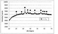
- the X-ray diffraction spectrum of an oxygen reduction catalyst (1) is shown.
- ⁇ indicates a peak of cubic CoS 2 .
- the X-ray diffraction spectrum of an oxygen reduction catalyst (11) is shown.
- the symbol ⁇ indicates a cubic CoS 2 peak, and the symbol ⁇ indicates a monoclinic CrS 2 peak.
- 2 shows an X-ray diffraction spectrum of an oxygen reduction catalyst (12).
- the symbol ⁇ indicates a cubic CoS 2 peak, and the symbol ⁇ indicates a hexagonal MoS 2 peak.
- the oxygen reduction catalyst of the present invention contains cobalt, sulfur, and transition metal element M, which is at least one element selected from the group consisting of chromium and molybdenum, as constituent elements.
- transition metal element M is at least one element selected from the group consisting of chromium and molybdenum, as constituent elements.
- a cubic crystal structure was confirmed, and the molar ratio of transition metal element M to cobalt (M / cobalt) was 5/95 to 15/85.
- the oxygen reduction catalyst of the present invention contains cobalt, sulfur, and a transition metal element M other than cobalt as constituent elements, and the transition metal element M is at least one element selected from the group consisting of chromium and molybdenum. It is. That is, the oxygen reduction catalyst of the present invention contains at least cobalt, sulfur and chromium; cobalt, sulfur and molybdenum; or cobalt, sulfur, chromium and molybdenum as constituent elements.
- the molar ratio (M / cobalt) of the transition metal element M to cobalt contained in the oxygen reduction catalyst of the present invention is 5/95 to 15/85, and is 7.5 / 92.5 to 15/85. It is preferably 10/90 to 15/85.
- the molar ratio (M / cobalt) is smaller than 5/95, Co and S are easily desorbed, and the durability as a catalyst is not sufficient.
- the molar ratio (M / cobalt) is larger than 15/85, the sulfide of the inactive transition metal element M alone is preferentially generated and the catalyst performance is deteriorated.
- the molar ratio is the total molar ratio of chromium and molybdenum. If unreacted sulfur that does not constitute cobalt sulfide remains, the durability of the oxygen reduction catalyst may be lowered. Therefore, it is preferable to remove unreacted sulfur sufficiently in the production method described later, but it may contain unreacted sulfur to the extent that the durability of the oxygen reduction catalyst is not deteriorated.
- the amount of sulfur contained in the oxygen reduction catalyst of the present invention is 1: 1.90 to 1: 2.10, preferably 1: 1.95 to 1: 2 with respect to the total of cobalt and the transition metal element M. .05 (total of cobalt and M: sulfur).
- the molar ratio of the above constituent elements can be confirmed by a normal elemental analysis method.
- the amount of sulfur contained in the catalyst can be obtained, for example, using a carbon sulfur analyzer EMIA-920V (manufactured by Horiba, Ltd.).
- the amount of metal such as cobalt contained in the catalyst is determined by completely thermally decomposing the sample using sulfuric acid, nitric acid, hydrofluoric acid, etc., and preparing a constant volume solution using an elemental analyzer VISTA-PRO (manufactured by SII). Can be obtained.
- the oxygen reduction catalyst of the present invention is confirmed to have a cubic crystal structure of cobalt disulfide by powder X-ray diffraction measurement. Although other crystal structures may be included as long as the catalytic properties are not reduced, the powder crystal X-ray diffraction measurement mainly confirms the cubic crystal structure of cobalt disulfide.
- the cubic crystal content of cobalt disulfide is preferably 80% or more.
- the cubic crystal content of cobalt disulfide is more preferably 90%, still more preferably 100%.
- the cubic crystal content of cobalt disulfide (hereinafter also referred to as “cubic CoS 2 content”) is the total amount of metal sulfide crystals confirmed by X-ray diffraction (XRD) measurement.
- the cubic CoS 2 content is a value obtained from the diffraction peak intensity of the XRD spectrum as follows.
- the peak intensity of the strongest diffraction intensity among the assigned peaks is determined for each crystal. Then, the intensity ratio obtained by multiplying the peak intensity of the cubic crystal of cobalt disulfide by a molecule and taking the ratio as a denominator and summing the peak intensity of all metal sulfide crystals including the cubic crystal of cobalt disulfide by a factor of 100. (%) Is the cubic CoS 2 content.
- the peak height (Hc) of the strongest diffraction intensity among the peaks attributed to the crystal of the crystal is obtained by subtracting the height of each baseline from the height of the peak of each peak, and the following calculation is performed.
- the cubic crystal content (cubic CoS 2 content) of cobalt disulfide in the oxygen reduction catalyst is obtained from the equation.
- Cubic CoS 2 content (%) [Ha / (Ha + Hb + Hc)] ⁇ 100
- Cubic CoS 2 content (%) [Ha / ⁇ Hs] ⁇ 100
- the oxygen reduction catalyst for example, when a crystal structure such as a monoclinic crystal structure of CrS 2 or a hexagonal crystal structure of MoS 2 exists and the cubic CoS 2 content is less than 80%, As shown, either or both of the oxygen reduction properties of the oxygen reduction catalyst are low, which is undesirable.
- X-ray diffraction measurement device for example, Panalytic MPD manufactured by Spectris Co., Ltd. can be used.
- measurement conditions for example, X-ray output (Cu-K ⁇ ): 45 kV, 180 mA, scanning axis: ⁇ / 2 ⁇ , measurement range (2 ⁇ ): 10 ° -90 °, measurement mode: FT, read width: 0.02 °, sampling time: 0.70 seconds, DS, SS, RS: 0.5 °, 0.5 °, 0.15 mm, goniometer radius: 185 mm.
- the oxygen reduction catalyst of the present invention contains chromium and / or molybdenum as a constituent element in addition to cobalt and sulfur, and thus has a higher catalytic activity than a catalyst containing a transition metal element other than chromium and molybdenum, such as tungsten. Can be expressed.
- the oxygen reduction catalyst of the present invention can be produced by synthesizing a metal sulfide and annealing the metal sulfide.
- a metal sulfide is synthesized by reacting a cobalt compound and a compound of the transition metal element M with a sulfur source.
- the cobalt compound is not particularly limited as long as it decomposes during the reaction to produce cobalt, but it is preferable to use a cobalt carbonyl compound in view of simplicity.
- octacarbonyl nicobalt or the like is preferably used.
- the compound of the transition metal element M is not particularly limited as long as it generates chromium and molybdenum, but it is preferable to use a carbonyl compound of the transition metal element M in consideration of simplicity.
- hexacarbonyl chromium, hexacarbonyl molybdenum and the like are preferably used.
- the amount of the cobalt compound and the compound of transition metal element M used is such that the molar ratio of transition metal element M to cobalt (M / cobalt) is 5/95 to 15/85.
- the molar ratio of sulfur to the total of cobalt and the transition metal element M is the molar ratio in the oxygen reduction catalyst in which the molar ratio of the charged amount can be obtained almost as it is.
- the molar ratio of sulfur to the total amount of transition metal element M contained in the transition metal compound at the time of charging is preferably in the range of 2 to 10, and more preferably in the range of 4 to 10. .
- cobalt sulfide having a low sulfur ratio such as Co 9 S 8 or CoS, is produced instead of cobalt disulfide. Performance will be degraded.
- the molar ratio is greater than 10, unreacted sulfur remains without being removed, and the durability of the resulting catalyst may be lowered.
- the reaction between the cobalt compound and the transition metal element M compound and the sulfur source is, for example, heated to a temperature lower than the boiling point of the solvent using a solvent such as p-xylene in an inert gas atmosphere such as nitrogen gas. It may be performed for 8 to 30 hours.
- the obtained metal sulfide powder is preferably removed sufficiently using a solvent such as p-xylene heated to below the boiling point so that unreacted sulfur does not remain.
- the metal sulfide produced in the above process is annealed.
- the atmosphere during annealing may be an inert atmosphere, and is preferably a nitrogen gas or argon gas atmosphere.
- the annealing temperature is usually 300 to 500 ° C., preferably 350 to 450 ° C.
- sulfur is easily desorbed, and is transferred from cobalt disulfide (CoS 2 ) to polymorphic cobalt sulfide (CoS) containing hexagonal crystals having poor oxygen reducing ability.
- CoS 2 cobalt disulfide
- CoS polymorphic cobalt sulfide
- sintering and particle growth occur between the particles of the obtained oxygen reduction catalyst, and the specific surface area of the catalyst becomes small, so the catalyst performance may be inferior.
- the annealing temperature is lower than 300 ° C., sufficient crystallinity cannot be obtained, and it becomes difficult to obtain a highly durable oxygen reduction catalyst.
- the annealing treatment time is usually 1 to 8 hours, preferably 2 to 6 hours. If the metal sulfide contains unreacted sulfur, it may sublime during the annealing process and adhere to the inside of the quartz tube of the annealing apparatus. Unreacted sulfur that could not be removed in the aforementioned synthesis step can also be removed during the annealing treatment.
- a catalyst layer for example, a fuel cell catalyst layer, can be produced from the oxygen reduction catalyst.
- the catalyst component of the catalyst layer is preferably composed of the oxygen reduction catalyst of the present invention.
- As the catalyst component there may be a promoter other than the oxygen reduction catalyst of the present invention, but it is not particularly necessary.
- the fuel cell catalyst layer includes the oxygen reduction catalyst and a polymer electrolyte.
- electron conductive particles may be further included in the catalyst layer.
- the material of the electron conductive particles examples include carbon, a conductive polymer, a conductive ceramic, a metal, or a conductive inorganic oxide such as tungsten oxide or iridium oxide, which can be used alone or in combination. .
- the electron conductive particles made of carbon have a large specific surface area, and are easily available with a small particle size at low cost and excellent in chemical resistance, carbon alone or carbon and other electron conductive particles can be used. Mixtures are preferred.
- Examples of carbon include carbon black, graphite, activated carbon, carbon nanotube, carbon nanofiber, carbon nanohorn, porous carbon, graphene, and the like. If the particle size of the electron conductive particles made of carbon is too small, it becomes difficult to form an electron conduction path. If the particle size is too large, the gas diffusibility of the fuel cell catalyst layer and the catalyst utilization rate tend to decrease. Therefore, the thickness is preferably 10 to 1000 nm, more preferably 10 to 100 nm.
- the mass ratio of the oxygen reduction catalyst to the electron conductive particles is preferably 1: 1 to 100: 1.
- the fuel cell catalyst layer usually contains a polymer electrolyte.
- the polymer electrolyte is not particularly limited as long as it is generally used in a fuel cell catalyst layer. Specifically, a perfluorocarbon polymer having a sulfonic acid group (for example, NAFION (registered trademark)), a hydrocarbon-based polymer compound having a sulfonic acid group, and a highly doped inorganic acid such as phosphoric acid.
- Examples thereof include molecular compounds, organic / inorganic hybrid polymers partially substituted with proton conductive functional groups, and proton conductors in which a polymer matrix is impregnated with a phosphoric acid solution or a sulfuric acid solution.
- Nafion registered trademark
- the method for forming the fuel cell catalyst layer is not particularly limited.
- the coating method include a dipping method, a screen printing method, a roll coating method, a spray method, and a bar coater coating method.
- a fuel cell catalyst layer is formed on the electrolyte membrane by a transfer method after forming a fuel cell catalyst layer on a substrate by applying a suspension in which the constituent materials of the fuel cell catalyst layer are dispersed in a solvent. The method of doing is mentioned.
- the electrode of this invention has the said catalyst layer for fuel cells, and is normally equipped with a gas diffusion layer.
- an electrode including the anode catalyst layer is referred to as an anode
- an electrode including the cathode catalyst layer is referred to as a cathode.
- the gas diffusion layer is a porous layer that assists gas diffusion.
- the gas diffusion layer may be anything as long as it has electron conductivity, high gas diffusibility, and high corrosion resistance.
- carbon-based porous materials such as carbon paper and carbon cloth are used. Material is used.
- the membrane electrode assembly of the present invention comprises a cathode and an anode, and a polymer electrolyte membrane disposed between the cathode and the anode, and the cathode and / or the anode is the electrode. Since the catalyst of the present invention has a high oxygen reducing ability, it is preferably used as a cathode.
- the membrane electrode assembly may have a gas diffusion layer.
- polymer electrolyte membrane for example, a polymer electrolyte membrane using a perfluorosulfonic acid polymer or a polymer electrolyte membrane using a hydrocarbon polymer is generally used.
- a membrane impregnated with a liquid electrolyte or a membrane filled with a polymer electrolyte in a porous body may be used.
- the cathode catalyst layer and the anode catalyst layer are sandwiched between the two surfaces of the electrolyte membrane with the gas diffusion layer. You can get it.
- the fuel cell of the present invention includes the membrane electrode assembly.
- the fuel cell include molten carbonate type (MCFC), phosphoric acid type (PAFC), solid oxide type (SOFC), and solid polymer type (PEFC).
- the membrane electrode assembly is preferably used for a polymer electrolyte fuel cell, and hydrogen, methanol, or the like can be used as a fuel.
- the PEFC of the present invention having the oxygen reduction catalyst has high durability under the operating environment.
- Example 1 Catalyst preparation step 0.654 g of sulfur powder (manufactured by Wako Pure Chemical Industries, Ltd.) and 150 mL of p-xylene (manufactured by Wako Pure Chemical Industries, Ltd.) are weighed, put into a four-necked flask, kept at 110 ° C. and nitrogen gas Refluxing was performed for 30 minutes under an atmosphere.
- the powder is placed in a nitrogen gas stream (gas flow rate 100 mL / min), heated from room temperature to 400 ° C. at a heating rate of 10 ° C./min, and calcined at 400 ° C. for 2 hours.
- An oxygen reduction catalyst (1) was obtained by annealing.
- Table 1 shows the molar ratio (mol%) of cobalt and chromium with respect to the total amount of 100 mol% of cobalt and chromium contained in the oxygen reduction catalyst (1). This molar ratio was calculated from the amount of raw materials used.
- the oxygen reduction activity of the oxygen reduction catalyst was measured as follows. A solution containing 15 mg of the obtained oxygen reduction catalyst (1), 1.0 mL of 2-propanol, 1.0 mL of ion exchange water and 62 ⁇ L of Nafion (NAFION (registered trademark), 5% aqueous Nafion solution, manufactured by Wako Pure Chemical Industries, Ltd.) The mixture was stirred and suspended with ultrasonic waves. 20 ⁇ L of this mixture was applied to a glassy carbon electrode (manufactured by Tokai Carbon Co., Ltd., diameter: 5.2 mm) and dried at 70 ° C. for 1 hour to obtain a catalyst electrode for measurement of catalytic activity.
- NAFION registered trademark
- 5% aqueous Nafion solution manufactured by Wako Pure Chemical Industries, Ltd.
- Electrochemical measurement of the oxygen reduction activity catalytic ability of the oxygen reduction catalyst (1) was performed as follows.
- the produced catalyst electrode was polarized in an oxygen gas atmosphere and a nitrogen gas atmosphere in a 0.5 mol / dm 3 sulfuric acid aqueous solution at a potential scanning speed of 30 mV and 5 mV / sec, and a current-potential curve was measured.
- a reversible hydrogen electrode in an aqueous sulfuric acid solution having the same concentration was used as a reference electrode.
- the electrode after measuring the catalytic activity was immersed in a 0.5 mol / dm 3 sulfuric acid aqueous solution at 80 ° C. for 8 hours. Thereafter, an electrode potential at 10 ⁇ A was obtained by the same operation as the measurement of the catalytic activity.
- the ratio (%) of the electrode potential at 10 ⁇ A after the acid immersion test to the electrode potential at 10 ⁇ A before the acid immersion test of the catalyst electrode was used as the retention rate, and this retention rate was used as an index of durability. Table 1 shows the retention rate of the electrode potential.
- the obtained XRD spectrum was subjected to baseline correction using the analysis software “High Score Plus” attached to the apparatus, and the baseline height was subtracted from the peak height.
- Baseline correction conditions were granularity: 30 and bending factor: 4, and were automatically set. It was determined with previously described cubic CoS 2 content, cubic CoS 2 content of the oxygen reduction catalyst (1) was 100%.
- the obtained XRD spectrum is shown in FIG.
- Example 2 An oxygen reduction catalyst (2) was produced in the same manner as in Example 1 except that the amount of octacarbonyl nicobalt was changed to 0.644 g and the amount of hexacarbonylchrome was changed to 0.08 g.
- Table 1 shows the molar ratio (mol%) of cobalt and chromium with respect to 100 mol% of the total amount of cobalt and chromium contained in the oxygen reduction catalyst (2).
- Example 1 powder X-ray diffraction measurement of the oxygen reduction catalyst (2) was performed. An XRD spectrum showing the same peak as in FIG. 1 was obtained. The crystal structure of the oxygen reduction catalyst (2) was identified as cubic CoS 2 . A diffraction peak indicating the presence of other crystals was not observed, and the content of cubic CoS 2 in the oxygen reduction catalyst (2) was 100%.
- Example 3 An oxygen reduction catalyst (3) was produced in the same manner as in Example 1 except that the amount of octacarbonyl nicobalt was changed to 0.608 g and the amount of hexacarbonylchromium was changed to 0.12 g.
- Table 1 shows the molar ratio (mol%) of cobalt and chromium with respect to 100 mol% of the total amount of cobalt and chromium contained in the oxygen reduction catalyst (3).
- powder X-ray diffraction measurement of the oxygen reduction catalyst (3) was performed.
- An XRD spectrum showing the same peak as in FIG. 1 was obtained.
- the crystal structure of the oxygen reduction catalyst (3) was identified as cubic CoS 2 .
- a diffraction peak indicating the presence of other crystals was not observed, and the content of cubic CoS 2 in the oxygen reduction catalyst (3) was 100%.
- Example 4 An oxygen reduction catalyst (4) was produced in the same manner as in Example 1 except that 0.04 g of hexacarbonyl chromium was changed to 0.049 g of hexacarbonyl molybdenum (manufactured by Wako Pure Chemical Industries, Ltd.).
- Table 1 shows the respective molar ratios (mol%) of cobalt and molybdenum with respect to 100 mol% of the total amount of cobalt and molybdenum contained in the oxygen reduction catalyst (4).
- powder X-ray diffraction measurement of the oxygen reduction catalyst (4) was performed.
- An XRD spectrum showing the same peak as in FIG. 1 was obtained.
- the crystal structure of the oxygen reduction catalyst (4) was identified as cubic CoS 2 .
- a diffraction peak indicating the presence of other crystals was not observed, and the content of cubic CoS 2 in the oxygen reduction catalyst (4) was 100%.
- Example 5 An oxygen reduction catalyst (5) was produced in the same manner as in Example 2 except that 0.08 g of hexacarbonyl chromium was changed to 0.098 g of hexacarbonyl molybdenum.
- Table 1 shows the respective molar ratios (mol%) of cobalt and molybdenum with respect to 100 mol% of the total amount of cobalt and molybdenum contained in the oxygen reduction catalyst (5).
- powder X-ray diffraction measurement of the oxygen reduction catalyst (5) was performed.
- An XRD spectrum showing the same peak as in FIG. 1 was obtained.
- the crystal structure of the oxygen reduction catalyst (5) was identified as cubic CoS 2 .
- a diffraction peak indicating the presence of other crystals was not observed, and the content of cubic CoS 2 in the oxygen reduction catalyst (5) was 100%.
- Example 6 An oxygen reduction catalyst (6) was produced in the same manner as in Example 3 except that 0.12 g of hexacarbonyl chromium was changed to 0.147 g of hexacarbonyl molybdenum.
- Table 1 shows the molar ratio (mol%) of cobalt and molybdenum with respect to 100 mol% of the total amount of cobalt and molybdenum contained in the oxygen reduction catalyst (6).
- powder X-ray diffraction measurement of the oxygen reduction catalyst (6) was performed.
- An XRD spectrum showing the same peak as in FIG. 1 was obtained.
- the crystal structure of the oxygen reduction catalyst (6) was identified as cubic CoS 2 .
- a diffraction peak indicating the presence of other crystals was not observed, and the content of cubic CoS 2 in the oxygen reduction catalyst (6) was 100%.
- Example 1 An oxygen reduction catalyst (7) was produced in the same manner as in Example 1 except that 0.715 g of only octacarbonyl nicobalt was added as a metal source.
- Example 2 powder X-ray diffraction measurement of the oxygen reduction catalyst (7) was performed. An XRD spectrum showing the same peak as in FIG. 1 was obtained. The crystal structure of the oxygen reduction catalyst (7) was identified as cubic CoS 2 . A diffraction peak indicating the presence of other crystals was not observed, and the content of cubic CoS 2 in the oxygen reduction catalyst (7) was 100%.
- Table 1 shows the respective molar ratios (mol%) of cobalt and tungsten with respect to 100 mol% of the total amount of cobalt and tungsten contained in the oxygen reduction catalyst (8).
- powder X-ray diffraction measurement of the oxygen reduction catalyst (8) was performed.
- An XRD spectrum showing the same peak as in FIG. 1 was obtained.
- the crystal structure of the oxygen reduction catalyst (8) was identified as cubic CoS 2 .
- a diffraction peak indicating the presence of other crystals was not observed, and the content of cubic CoS 2 in the oxygen reduction catalyst (8) was 100%.
- Table 1 shows the molar ratio (mol%) of cobalt and tungsten with respect to 100 mol% of the total amount of cobalt and tungsten contained in the oxygen reduction catalyst (9).
- powder X-ray diffraction measurement of the oxygen reduction catalyst (9) was performed.
- An XRD spectrum showing the same peak as in FIG. 1 was obtained.
- the crystal structure of the oxygen reduction catalyst (9) was identified as cubic CoS 2 .
- a diffraction peak indicating the presence of other crystals was not observed, and the content of cubic CoS 2 in the oxygen reduction catalyst (9) was 100%.
- Table 1 shows the molar ratio (mol%) of cobalt and tungsten with respect to 100 mol% of the total amount of cobalt and tungsten contained in the oxygen reduction catalyst (10).
- Example 1 powder X-ray diffraction measurement of the oxygen reduction catalyst (10) was performed. An XRD spectrum showing the same peak as in FIG. 1 was obtained. The crystal structure of the oxygen reduction catalyst (10) was identified as cubic CoS 2 . A diffraction peak indicating the presence of other crystals was not observed, and the content of cubic CoS 2 in the oxygen reduction catalyst (10) was 100%.
- An oxygen reduction catalyst (11) was produced in the same manner as in Example 1 except that the amount of octacarbonyl nicobalt was changed to 0.572 g and the amount of hexacarbonyl chromium was changed to 0.16 g.
- Table 1 shows the respective molar ratios (mol%) of cobalt and chromium with respect to 100 mol% of the total amount of cobalt and chromium contained in the oxygen reduction catalyst (11).
- powder X-ray diffraction measurement of the oxygen reduction catalyst (11) was performed.
- an XRD spectrum showing a characteristic peak corresponding to monoclinic CrS 2 at 26.3 ° in the reference code 01-072-4210 was obtained.
- the obtained XRD spectrum is shown in FIG.
- the cubic CoS 2 content of the oxygen reduction catalyst (11) was 79%.
- Table 1 shows the respective molar ratios (mol%) of cobalt and molybdenum with respect to 100 mol% of the total amount of cobalt and molybdenum contained in the oxygen reduction catalyst (12).
- powder X-ray diffraction measurement of the oxygen reduction catalyst (12) was performed.
- an XRD spectrum showing a characteristic peak corresponding to hexagonal MoS 2 at 14.4 ° in the reference code 98-002-4000 although the crystallinity was slightly low was obtained. .
- the obtained XRD spectrum is shown in FIG.
- the cubic CoS 2 content of the oxygen reduction catalyst (12) was 77%.
- Example 1 the electrode potential before and after acid immersion by electrochemical measurement, the electrode potential retention rate by acid immersion test, and the cobalt dissolution rate by acid dissolution test were measured. The results are shown in Table 1.
- the oxygen reduction catalyst of the present invention can be used for PEFC as an alternative to platinum, which is a conventionally used catalyst.
Landscapes
- Chemical & Material Sciences (AREA)
- Engineering & Computer Science (AREA)
- Chemical Kinetics & Catalysis (AREA)
- Materials Engineering (AREA)
- Electrochemistry (AREA)
- General Chemical & Material Sciences (AREA)
- Life Sciences & Earth Sciences (AREA)
- Manufacturing & Machinery (AREA)
- Sustainable Development (AREA)
- Sustainable Energy (AREA)
- Organic Chemistry (AREA)
- Catalysts (AREA)
- Inert Electrodes (AREA)
- Fuel Cell (AREA)
Abstract
本発明は、コバルトと、硫黄と、クロムおよびモリブデンからなる群から選ばれる少なくとも1つの元素である遷移金属元素Mとを構成元素として含み、粉末X線回折測定において二硫化コバルトの立方晶の結晶構造を有することが確認され、遷移金属元素Mとコバルトとのモル比(M/コバルト)が5/95~15/85である酸素還元触媒である。本発明の酸素還元触媒は、活性が高く、かつ高い耐久性を有し、白金の代替となり得る酸素還元触媒である。具体的には、本発明の酸素還元触媒は、PEFCの作動環境下において高い耐久性を有し、酸性雰囲気でのCo溶出率の抑制、酸浸漬試験前後での酸素還元電位の高い保持率を実現できる。
Description
本発明は、酸素還元触媒、膜電極接合体及び燃料電池に関し、詳しくは、白金の代替となる二硫化コバルトを含有する酸素還元触媒、ならびに、それを用いた膜電極接合体及び燃料電池に関する。
固体高分子型燃料電池(PEFC)は、固体高分子電解質をアノードとカソードとで挟み、アノードに燃料を、カソードに酸素または空気をそれぞれ供給し、カソードにおいて酸素が還元されることで電気を取り出す形式を有する燃料電池である。燃料には水素またはメタノールなどが主として用いられる。従来、PEFCの反応速度を高め、またPEFCのエネルギー変換効率を高めるために、燃料電池のカソード表面やアノード表面には、触媒を含む層が設けられている。この触媒としては、一般的に貴金属が用いられており、貴金属の中でも活性が高い白金が主として用いられる。
PEFCの用途拡大に向けては、触媒の低コスト化の試み、とりわけカソードに用いられる酸素還元触媒を非白金化して安価な酸素還元触媒を得る試みがなされている。
一方、PEFCのカソードは強酸性かつ酸化性雰囲気中に置かれ、さらに作動時には電位が高いことから、PEFCの作動環境下において安定な触媒材料は非常に限られる。かかる環境においては、貴金属の中で特に安定な白金を触媒に用いた場合であっても、長期的な使用によりカソード触媒が酸化されて失活したり、溶解脱落を起こしたりして、活性が低下してしまうことが知られている。このことから、PEFCの発電性能を維持する点でも、カソード触媒に多量の貴金属を使用する必要があり、コスト面および資源面の双方において大きな課題となっている。
一方、PEFCのカソードは強酸性かつ酸化性雰囲気中に置かれ、さらに作動時には電位が高いことから、PEFCの作動環境下において安定な触媒材料は非常に限られる。かかる環境においては、貴金属の中で特に安定な白金を触媒に用いた場合であっても、長期的な使用によりカソード触媒が酸化されて失活したり、溶解脱落を起こしたりして、活性が低下してしまうことが知られている。このことから、PEFCの発電性能を維持する点でも、カソード触媒に多量の貴金属を使用する必要があり、コスト面および資源面の双方において大きな課題となっている。
以上のことから、触媒活性が高く、なおかつPEFCの作動環境下において高い耐久性を有する非白金系の酸素還元触媒が求められていた。
金属硫化物は、バンドギャップが小さく、金属並みの導電性を示すことから、光触媒や酸化還元反応に関わる電極触媒として用いられている。その中でも、硫化コバルトは、金属硫化物触媒の酸素還元触媒能を利用して、燃料電池の電極触媒に使用することも可能であることが知られている。しかし、その一方で、硫化コバルトは、その耐久性が問題視されていた。
金属硫化物は、バンドギャップが小さく、金属並みの導電性を示すことから、光触媒や酸化還元反応に関わる電極触媒として用いられている。その中でも、硫化コバルトは、金属硫化物触媒の酸素還元触媒能を利用して、燃料電池の電極触媒に使用することも可能であることが知られている。しかし、その一方で、硫化コバルトは、その耐久性が問題視されていた。
特許文献1では、第4~8族の遷移金属2種類と硫黄を真空焼成することで、遷移金属二硫化物結晶層に触媒活性金属がインターカレートした層状の金属硫化物を作製し、ある特定の組成において比抵抗の小さい白金フリー燃料電池触媒を報告している。
特許文献2は、硫化ルテニウムにモリブデンを添加することで、硫化ルテニウム単独よりも硫黄が脱離しにくくなり、より高い耐久性を有する触媒の製造が可能であることを報告している。
非特許文献1は、チオスピネル化合物Co3S4に遷移金属元素がドープされた触媒の酸素還元挙動について報告している。
特許文献1記載のNbS2をはじめとする層状化合物は酸化安定性が低いことが知られており、耐久性が求められる燃料電池触媒として好ましくない。また、特許文献1では、固相法で触媒を作製しているので、得られる触媒は比表面積が小さく、高出力が求められる燃料電池触媒として好ましくない。
特許文献1記載のNbS2をはじめとする層状化合物は酸化安定性が低いことが知られており、耐久性が求められる燃料電池触媒として好ましくない。また、特許文献1では、固相法で触媒を作製しているので、得られる触媒は比表面積が小さく、高出力が求められる燃料電池触媒として好ましくない。
特許文献2では、貴金属であるRuを触媒に使用しており、コストの面で好ましくない。
非特許文献1に記載のCo3S4は、そもそもCoS2よりも酸素還元能が低い。さらに、CrおよびMoの遷移金属元素がドープされた触媒の酸素還元能はむしろ低下していることが記載されている。また非特許文献1では、CoS2に遷移金属元素がドープされた触媒については記載も示唆もない。
非特許文献1に記載のCo3S4は、そもそもCoS2よりも酸素還元能が低い。さらに、CrおよびMoの遷移金属元素がドープされた触媒の酸素還元能はむしろ低下していることが記載されている。また非特許文献1では、CoS2に遷移金属元素がドープされた触媒については記載も示唆もない。
Electrochimica Acta 1975,20,111-117
本発明は前述のような従来技術の下、触媒活性が高く、かつ高い耐久性を有し、白金の代替となり得る酸素還元触媒を提供することを目的とする。
本発明者らは、上記従来技術の問題点を解決すべく鋭意検討した結果、コバルトと、硫黄と、クロムおよびモリブデンからなる群から選ばれる少なくとも1つの元素である遷移金属元素Mとを構成元素として含む、特定の結晶構造を有し、遷移金属元素Mとコバルトとのモル比が特定の範囲である触媒が、活性が高く、かつ高い耐久性を有し、白金の代替となり得る酸素還元触媒であることを見出し、本発明を完成するに至った。
本発明は、例えば以下の[1]~[5]に関する。
[1]
コバルトと、硫黄と、クロムおよびモリブデンからなる群から選ばれる少なくとも1つの元素である遷移金属元素Mとを構成元素として含み、粉末X線回折測定において二硫化コバルトの立方晶の結晶構造を有することが確認され、遷移金属元素Mとコバルトとのモル比(M/コバルト)が5/95~15/85である酸素還元触媒。
[1]
コバルトと、硫黄と、クロムおよびモリブデンからなる群から選ばれる少なくとも1つの元素である遷移金属元素Mとを構成元素として含み、粉末X線回折測定において二硫化コバルトの立方晶の結晶構造を有することが確認され、遷移金属元素Mとコバルトとのモル比(M/コバルト)が5/95~15/85である酸素還元触媒。
[2]
二硫化コバルトの立方晶の結晶含有率が80%以上である前記[1]に記載の酸素還元触媒。
二硫化コバルトの立方晶の結晶含有率が80%以上である前記[1]に記載の酸素還元触媒。
[3]
前記[1]または[2]に記載の酸素還元触媒を含む触媒層を有する電極。
前記[1]または[2]に記載の酸素還元触媒を含む触媒層を有する電極。
[4]
カソードとアノードとの間に高分子電解質膜を配置した膜電極接合体において、前記[3]に記載の電極を前記カソード及び/又はアノードとして用いた、膜電極接合体。
カソードとアノードとの間に高分子電解質膜を配置した膜電極接合体において、前記[3]に記載の電極を前記カソード及び/又はアノードとして用いた、膜電極接合体。
[5]
前記[4]に記載の膜電極接合体を備える燃料電池。
前記[4]に記載の膜電極接合体を備える燃料電池。
本発明の酸素還元触媒は、活性が高く、かつ高い耐久性を有し、白金の代替となり得る酸素還元触媒である。具体的には、本発明の酸素還元触媒は、高い電極電位を有し、PEFCの作動環境下において高い耐久性を有し、酸性雰囲気でのCo溶出率の抑制および酸浸漬試験前後での酸素還元電位の高い保持率を実現することができる。
本発明の酸素還元触媒は、コバルトと、硫黄と、クロムおよびモリブデンからなる群から選ばれる少なくとも1つの元素である遷移金属元素Mとを構成元素として含み、粉末X線回折測定において二硫化コバルトの立方晶の結晶構造を有することが確認され、遷移金属元素Mとコバルトとのモル比(M/コバルト)が5/95~15/85である。
本発明の酸素還元触媒は構成元素として、コバルトと、硫黄と、コバルト以外の遷移金属元素Mとを構成元素として含み、前記遷移金属元素Mはクロムおよびモリブデンからなる群から選ばれる少なくとも1つの元素である。すなわち、本発明の酸素還元触媒は、構成元素として少なくとも、コバルト、硫黄およびクロム;コバルト、硫黄およびモリブデン;またはコバルト、硫黄、クロムおよびモリブデンを含む。
本発明の酸素還元触媒に含まれる前記遷移金属元素Mのコバルトに対するモル比(M/コバルト)は5/95~15/85であり、7.5/92.5~15/85であることが好ましく、10/90~15/85であることがより好ましい。モル比(M/コバルト)が5/95より小さい場合には、CoやSが脱離しやすく、触媒としての耐久性が十分でない。またモル比(M/コバルト)が15/85より大きい場合には、不活性な遷移金属元素M単独の硫化物が優先して生成し、触媒性能が低下してしまう。
本発明の酸素還元触媒が遷移金属元素Mとしてクロムおよびモリブデンの両方を含む場合には、前記モル比はクロムおよびモリブデンの合計のモル比である。コバルト硫化物を構成しない未反応の硫黄が残存すると、酸素還元触媒の耐久性を低くする可能性が有る。よって、未反応の硫黄は後述する製造方法において十分に取り除くことが好ましいが、酸素還元触媒の耐久性を劣下させない程度に未反応の硫黄を含んでいてもよい。
本発明の酸素還元触媒が含む硫黄の量は、コバルトと前記遷移金属元素Mの合計に対して1:1.90~1:2.10であり、好ましくは1:1.95~1:2.05(コバルトとMとの合計:硫黄)である。以上の構成元素のモル比は、通常の元素分析方法により確認することができる。触媒が含む硫黄の量は、例えば炭素硫黄分析装置EMIA-920V(堀場製作所製)を用いて得ることができる。触媒が含むコバルト等金属の量は、試料を硫酸、硝酸およびフッ酸等を適宜用いて完全に加熱分解し、定容した溶液を作製して元素分析装置VISTA―PRO(SII社製)を用いて測定して得ることができる。
本発明の酸素還元触媒は、粉末X線回折測定において二硫化コバルトの立方晶の結晶構造を有することが確認される。触媒特性を減じない範囲において他の結晶構造を含んでいても構わないが、粉末X線回折測定において、主として二硫化コバルトの立方晶の結晶構造が確認される。
本発明の酸素還元触媒は、二硫化コバルトの立方晶の結晶含有率が好ましくは80%以上である。二硫化コバルトの立方晶の結晶含有率は、より好ましくは90%であり、さらに好ましくは100%である。本願明細書において、二硫化コバルトの立方晶の結晶含有率(以下、「立方晶CoS2含有率」ともいう)とは、X線回折(XRD)測定において確認される金属硫化物の結晶の全量に対する二硫化コバルトの立方晶の結晶の含有量の百分率をいう。この立方晶CoS2含有率は、以下のとおり、XRDスペクトルの回折ピーク強度から求めた値である。
酸素還元触媒のXRDスペクトルにおいて確認される二硫化コバルトの立方晶の結晶を含むすべての金属硫化物の結晶について、帰属されるピークのうち最も強い回折強度のピーク強度を結晶ごとにそれぞれ求める。そして、二硫化コバルトの立方晶の結晶のピーク強度を分子とし、二硫化コバルトの立方晶の結晶を含むすべての金属硫化物結晶のピーク強度の和を分母として比をとって100倍した強度比率(%)を立方晶CoS2含有率とする。
一例としてXRDスペクトルにおいて二硫化コバルトの立方晶の結晶、硫化クロムの単斜晶の結晶および硫化モリブデンの六方晶の結晶が確認される場合には、二硫化コバルトの立方晶の結晶に帰属されるピークのうちの最も強い回折強度のピークの高さ(Ha)、硫化クロムの単斜晶の結晶に帰属されるピークのうちの最も強い回折強度のピーク高さ(Hb)、および硫化モリブデンの六方晶の結晶に帰属されるピークのうちの最も強い回折強度のピークの高さ(Hc)を、各ピークの頂点の高さからそれぞれのベースラインの高さを差し引くことにより求めて、以下の計算式により酸素還元触媒中における二硫化コバルトの立方晶の結晶含有率(立方晶CoS2含有率)を求める。
立方晶CoS2含有率(%)=[Ha/(Ha+Hb+Hc)]×100
一般式としては、二硫化コバルトの立方晶の結晶を含むすべての金属硫化物の結晶のピーク強度の和をΣHsとすると次のように表される。
立方晶CoS2含有率(%)=[Ha/ΣHs]×100
酸素還元触媒中において、例えば、CrS2の単斜晶の結晶構造やMoS2の六方晶等の結晶構造が存在して、立方晶CoS2含有率が80%より小さい場合、後述する比較例に示すように酸素還元触媒の酸素還元特性のいずれかまたは両方が低く、好ましくない。
立方晶CoS2含有率(%)=[Ha/(Ha+Hb+Hc)]×100
一般式としては、二硫化コバルトの立方晶の結晶を含むすべての金属硫化物の結晶のピーク強度の和をΣHsとすると次のように表される。
立方晶CoS2含有率(%)=[Ha/ΣHs]×100
酸素還元触媒中において、例えば、CrS2の単斜晶の結晶構造やMoS2の六方晶等の結晶構造が存在して、立方晶CoS2含有率が80%より小さい場合、後述する比較例に示すように酸素還元触媒の酸素還元特性のいずれかまたは両方が低く、好ましくない。
X線回折測定装置としては、例えばスペクトリス株式会社製パナリティカルMPD等を用いることができる。測定条件としては、例えば、X線出力(Cu-Kα):45kV、180mA、走査軸 :θ/2θ、測定範囲(2θ):10° ~90° 、測定モード:FT、読込幅 :0.02°、サンプリング時間:0.70秒、DS、SS、RS:0.5°、0.5°、0.15mm、ゴニオメーター半径:185mmを挙げることができる。
粉末X線回折測定において、リファレンスコード01-070-2865の結晶情報にある2θ=32.4°、36.3°、39.9°、46.4°および55.1°に相当する回折ピークが観測されたとき、触媒が二硫化コバルトの立方晶の結晶構造を有することが確認される。これらのピークは、触媒が構成元素として含むクロムの量に相関をもって高角にシフトし、モリブデンの量に相関をもって低角にシフトし、クロムおよびモリブデンの両方を含む場合にはそれぞれのシフトの量が相殺された結果の分だけ高角または低角にシフトする。
本発明の酸素還元触媒は、構成元素として、コバルトおよび硫黄以外にクロムおよび/またはモリブデンを含むことにより、クロムおよびモリブデン以外の遷移金属元素、たとえばタングステン等を含む触媒に比較して、高い触媒活性を発現することができる。
<酸素還元触媒の製造方法>
本発明の酸素還元触媒は、金属硫化物の合成と該金属硫化物のアニール処理とによって製造することができる。
本発明の酸素還元触媒は、金属硫化物の合成と該金属硫化物のアニール処理とによって製造することができる。
(金属硫化物の合成)
コバルト化合物および遷移金属元素Mの化合物を硫黄源と反応させて金属硫化物を合成する。
コバルト化合物としては、反応中に分解してコバルトを生成するものであれば特に制限はないが、簡便性を考えて、コバルトのカルボニル化合物を用いることが好ましい。具体的には、オクタカルボニルニコバルト等が好適に使用される。遷移金属元素Mの化合物もクロム、モリブデンを生成するものであれば特に制限はないが、簡便性を考えて、遷移金属元素Mのカルボニル化合物を用いることが好ましい。具体的には、ヘキサカルボニルクロム、ヘキサカルボニルモリブデン等が好適に使用される。
コバルト化合物および遷移金属元素Mの化合物を硫黄源と反応させて金属硫化物を合成する。
コバルト化合物としては、反応中に分解してコバルトを生成するものであれば特に制限はないが、簡便性を考えて、コバルトのカルボニル化合物を用いることが好ましい。具体的には、オクタカルボニルニコバルト等が好適に使用される。遷移金属元素Mの化合物もクロム、モリブデンを生成するものであれば特に制限はないが、簡便性を考えて、遷移金属元素Mのカルボニル化合物を用いることが好ましい。具体的には、ヘキサカルボニルクロム、ヘキサカルボニルモリブデン等が好適に使用される。
コバルト化合物および遷移金属元素Mの化合物の使用量は、コバルトに対する遷移金属元素Mのモル比(M/コバルト)が5/95~15/85となる量である。コバルトと前記遷移金属元素Mとの合計に対する硫黄のモル比は、仕込み量のモル比がほぼそのまま得られる酸素還元触媒におけるモル比になる。
硫黄源としては、硫黄粉が好ましい。仕込時の、遷移金属化合物に含まれる遷移金属元素M全量に対する硫黄のモル比(硫黄/M)としては、2~10の範囲であることが好ましく、4~10の範囲であることがより好ましい。前記モル比が2より小さい場合には、二硫化コバルトではなく、硫黄比率の低いCo9S8、CoS等の組成を有する酸素還元能の低いコバルト硫化物が生成されるので、得られる触媒の性能が低下してしまう。また前記モル比が10より大きい場合には、未反応の硫黄が除去しきれずに残存してしまい、得られる触媒の耐久性を低くする可能性が有る。
コバルト化合物および遷移金属元素Mの化合物と硫黄源との反応は、たとえば、窒素ガス等の不活性ガス雰囲気で、p-キシレン等の溶媒を用いて、溶媒の沸点未満に加温して還流下8~30時間行えばよい。得られた金属硫化物の粉体は、未反応の硫黄が残存しないよう沸点未満に加温したp-キシレン等の溶媒を用いて十分に取り除くことが好ましい。
(金属硫化物のアニール処理)
上記工程で製造された金属硫化物をアニール処理する。
アニール処理時の雰囲気は不活性雰囲気であれば良く、窒素ガスまたはアルゴンガス雰囲気であることが好ましい。
上記工程で製造された金属硫化物をアニール処理する。
アニール処理時の雰囲気は不活性雰囲気であれば良く、窒素ガスまたはアルゴンガス雰囲気であることが好ましい。
前記アニール処理の温度は、通常300~500℃であり、好ましくは350~450℃である。アニール処理温度が500℃より高いと、硫黄が脱離しやすくなり、二硫化コバルト(CoS2)から酸素還元能の劣る六方晶を含む多形の硫化コバルト(CoS)へ転移してしまう。また得られる酸素還元触媒の粒子相互間においての焼結、粒子成長が起こり、触媒の比表面積が小さくなるので、触媒性能が劣る場合がある。一方、アニール処理温度が300℃よりも低いと、十分な結晶性が得られないので、耐久性の高い酸素還元触媒を得ることが困難になる。
アニール処理の時間は、通常1~8時間、好ましくは2~6時間である。金属硫化物に未反応の硫黄が含まれている場合、アニール処理の際に昇華してアニール装置の石英管の内側に付着することがある。前述の合成工程において除去しきれなかった未反応の硫黄を、アニール処理の際に除去することもできる。
<触媒層>
前記酸素還元触媒から触媒層、例えば燃料電池用触媒層を製造することができる。
前記触媒層の触媒成分としては、本願発明の酸素還元触媒からなることが好ましい。触媒成分としては、本願発明の酸素還元触媒以外の助触媒があってもかまわないが、特に必要ではない。
前記酸素還元触媒から触媒層、例えば燃料電池用触媒層を製造することができる。
前記触媒層の触媒成分としては、本願発明の酸素還元触媒からなることが好ましい。触媒成分としては、本願発明の酸素還元触媒以外の助触媒があってもかまわないが、特に必要ではない。
燃料電池用触媒層は、前記酸素還元触媒と高分子電解質とを含む。前記触媒層中における電気抵抗をより低減させるために、電子伝導性粒子をさらに前記触媒層中に含ませてもよい。
電子伝導性粒子の材質としては、炭素、導電性高分子、導電性セラミックス、金属または酸化タングステンもしくは酸化イリジウムなどの導電性無機酸化物が挙げられ、それらを1種単独または組み合わせて用いることができる。特に、炭素からなる電子伝導性粒子は比表面積が大きいため、また、安価に小粒径のものを入手しやすく、耐薬品性に優れるため、炭素単独または炭素とその他の電子伝導性粒子との混合物が好ましい。
炭素としては、カーボンブラック、グラファイト、活性炭、カーボンナノチューブ、カーボンナノファイバー、カーボンナノホーン、多孔体カーボン、グラフェンなどが挙げられる。炭素からなる電子伝導性粒子の粒径は、小さすぎると電子伝導パスが形成されにくくなり、また大きすぎると燃料電池用触媒層のガス拡散性の低下や触媒の利用率の低下が起こる傾向があるため、好ましくは10~1000nmであり、より好ましくは10~100nmである。
電子伝導性粒子が炭素からなる場合、前記酸素還元触媒と電子伝導性粒子との質量比(触媒:電子伝導性粒子)は、好ましくは1:1~100:1である。
前記燃料電池用触媒層は、通常、高分子電解質を含む。前記高分子電解質としては、燃料電池用触媒層において一般的に用いられているものであれば特に限定されない。具体的には、スルホン酸基を有するパーフルオロカーボン重合体(例えば、ナフィオン(NAFION(登録商標)))、スルホン酸基を有する炭化水素系高分子化合物、リン酸などの無機酸をドープさせた高分子化合物、一部がプロトン伝導性の官能基で置換された有機/無機ハイブリッドポリマー、高分子マトリックスにリン酸溶液や硫酸溶液を含浸させたプロトン伝導体などが挙げられる。これらの中でも、ナフィオン(NAFION(登録商標))が好ましい。前記燃料電池用触媒層を形成する際のナフィオン(NAFION(登録商標))の供給源としては、5%ナフィオン(NAFION(登録商標))溶液(DE521、デュポン社製)などが挙げられる。
前記燃料電池用触媒層は、通常、高分子電解質を含む。前記高分子電解質としては、燃料電池用触媒層において一般的に用いられているものであれば特に限定されない。具体的には、スルホン酸基を有するパーフルオロカーボン重合体(例えば、ナフィオン(NAFION(登録商標)))、スルホン酸基を有する炭化水素系高分子化合物、リン酸などの無機酸をドープさせた高分子化合物、一部がプロトン伝導性の官能基で置換された有機/無機ハイブリッドポリマー、高分子マトリックスにリン酸溶液や硫酸溶液を含浸させたプロトン伝導体などが挙げられる。これらの中でも、ナフィオン(NAFION(登録商標))が好ましい。前記燃料電池用触媒層を形成する際のナフィオン(NAFION(登録商標))の供給源としては、5%ナフィオン(NAFION(登録商標))溶液(DE521、デュポン社製)などが挙げられる。
燃料電池用触媒層の形成方法としては、特に制限はないが、たとえば、前述の燃料電池触媒層の構成材料を溶媒に分散した懸濁液を、後述する電解質膜またはガス拡散層に塗布する方法が挙げられる。前記塗布する方法としては、ディッピング法、スクリーン印刷法、ロールコーティング法、スプレー法、バーコーター塗布法などが挙げられる。また、前述の燃料電池触媒層の構成材料を溶媒に分散した懸濁液を、塗布法により基材に燃料電池用触媒層を形成した後、転写法で電解質膜に燃料電池用触媒層を形成する方法が挙げられる。
<電極>
本発明の電極は、前記燃料電池用触媒層を有し、通常ガス拡散層を備える。以下、アノード触媒層を含む電極をアノードと、カソード触媒層を含む電極をカソードと呼ぶ。
本発明の電極は、前記燃料電池用触媒層を有し、通常ガス拡散層を備える。以下、アノード触媒層を含む電極をアノードと、カソード触媒層を含む電極をカソードと呼ぶ。
ガス拡散層とは、多孔質で、ガスの拡散を補助する層である。ガス拡散層としては、電子伝導性を有し、ガスの拡散性が高く、耐食性の高いものであれば何であっても構わないが、一般的にはカーボンペーパー、カーボンクロスなどの炭素系多孔質材料が用いられる。
<膜電極接合体>
本発明の膜電極接合体は、カソードとアノードと、前記カソードおよびアノードの間に配置された高分子電解質膜とで構成され、前記カソード及び/またはアノードが前記電極である。本発明の触媒は酸素還元能が高いので、カソードとして用いることが好ましい。また、前記膜電極接合体は、ガス拡散層を有していてもよい。
本発明の膜電極接合体は、カソードとアノードと、前記カソードおよびアノードの間に配置された高分子電解質膜とで構成され、前記カソード及び/またはアノードが前記電極である。本発明の触媒は酸素還元能が高いので、カソードとして用いることが好ましい。また、前記膜電極接合体は、ガス拡散層を有していてもよい。
高分子電解質膜としては、例えば、パーフルオロスルホン酸系高分子を用いた高分子電解質膜または炭化水素系高分子を用いた高分子電解質膜などが一般的に用いられるが、高分子微多孔膜に液体電解質を含浸させた膜または多孔質体に高分子電解質を充填させた膜などを用いてもよい。
前記膜電極接合体は、電解質膜および/またはガス拡散層に前記燃料電池用触媒層を形成後、カソード触媒層およびアノード触媒層を内側として電解質膜の両面をガス拡散層で挟み、例えばホットプレスすることで得ることができる。
<燃料電池>
本発明の燃料電池は、前記膜電極接合体を備える。前記燃料電池としては、溶融炭酸塩型(MCFC)、リン酸型(PAFC)、固体酸化物型(SOFC)、固体高分子型(PEFC)等を挙げることができる。中でも、前記膜電極接合体は、固体高分子型燃料電池に使用することが好ましく、燃料として水素やメタノール等を用いることができる。
本発明の燃料電池は、前記膜電極接合体を備える。前記燃料電池としては、溶融炭酸塩型(MCFC)、リン酸型(PAFC)、固体酸化物型(SOFC)、固体高分子型(PEFC)等を挙げることができる。中でも、前記膜電極接合体は、固体高分子型燃料電池に使用することが好ましく、燃料として水素やメタノール等を用いることができる。
前記酸素還元触媒は、PEFCの作動環境下において高い耐久性を有するので、前記酸素還元触媒を有する本発明のPEFCは、作動環境下において高い耐久性を有する。
以下に、本発明を実施例により具体的に説明するが、本発明はこれらの実施例に限定されない。
[実施例1]
(1)触媒作製工程
硫黄粉(和光純薬工業社製)0.654g、p-キシレン(和光純薬工業社製)150mLを秤量し、四つ口フラスコに入れ、110℃に保って窒素ガス雰囲気下で30分間還流を行った。室温に冷却後、オクタカルボニルニコバルト(和光純薬工業社製)0.679g、ヘキサカルボニルクロム(和光純薬工業社製)0.04gを秤量し、四つ口フラスコに添加した。再度、110℃に保って窒素ガス雰囲気下で24時間還流を行った。室温に冷却後、エタノール(和光純薬工業社製)を用いて、ろ過洗浄を行い、真空乾燥機にて6時間乾燥させ、粉体を得た。
[実施例1]
(1)触媒作製工程
硫黄粉(和光純薬工業社製)0.654g、p-キシレン(和光純薬工業社製)150mLを秤量し、四つ口フラスコに入れ、110℃に保って窒素ガス雰囲気下で30分間還流を行った。室温に冷却後、オクタカルボニルニコバルト(和光純薬工業社製)0.679g、ヘキサカルボニルクロム(和光純薬工業社製)0.04gを秤量し、四つ口フラスコに添加した。再度、110℃に保って窒素ガス雰囲気下で24時間還流を行った。室温に冷却後、エタノール(和光純薬工業社製)を用いて、ろ過洗浄を行い、真空乾燥機にて6時間乾燥させ、粉体を得た。
次に石英管状炉を用いて粉体を窒素ガス気流下(ガス流量100mL/分)に置いて、昇温速度10℃/分で室温から400℃まで昇温し、400℃で2時間焼成してアニール処理を行うことで、酸素還元触媒(1)を得た。
酸素還元触媒(1)に含有されるコバルトとクロムとの合計量100モル%に対するコバルトおよびクロムのそれぞれのモル比(mol%)を表1に示す。このモル比は、用いた原材料の仕込量から計算して求めた。
(2)電気化学測定
(触媒電極作製)
酸素還元触媒の酸素還元活性測定は次のように行った。得られた酸素還元触媒(1)15mg、2-プロパノール1.0mL、イオン交換水1.0mL及びナフィオン(NAFION(登録商標)、5%ナフィオン水溶液、和光純薬工業社製)62μLを含む溶液を超音波で攪拌、懸濁して混合した。この混合物20μLをグラッシーカーボン電極(東海カーボン社製、直径:5.2mm)に塗布し、70℃で1時間乾燥し、触媒活性測定の触媒電極を得た。
(触媒電極作製)
酸素還元触媒の酸素還元活性測定は次のように行った。得られた酸素還元触媒(1)15mg、2-プロパノール1.0mL、イオン交換水1.0mL及びナフィオン(NAFION(登録商標)、5%ナフィオン水溶液、和光純薬工業社製)62μLを含む溶液を超音波で攪拌、懸濁して混合した。この混合物20μLをグラッシーカーボン電極(東海カーボン社製、直径:5.2mm)に塗布し、70℃で1時間乾燥し、触媒活性測定の触媒電極を得た。
(触媒活性測定)
酸素還元触媒(1)の酸素還元活性触媒能の電気化学測定は、次のように行った。作製した触媒電極を、酸素ガス雰囲気及び窒素ガス雰囲気で、0.5mol/dm3の硫酸水溶液中、30℃、5mV/秒の電位走査速度で分極し、電流―電位曲線を測定した。その際、同濃度の硫酸水溶液中での可逆水素電極を参照電極とした。
酸素還元触媒(1)の酸素還元活性触媒能の電気化学測定は、次のように行った。作製した触媒電極を、酸素ガス雰囲気及び窒素ガス雰囲気で、0.5mol/dm3の硫酸水溶液中、30℃、5mV/秒の電位走査速度で分極し、電流―電位曲線を測定した。その際、同濃度の硫酸水溶液中での可逆水素電極を参照電極とした。
前記電気化学測定の結果より、酸素ガス雰囲気での還元電流から窒素ガス雰囲気での還元電流を引いて得られた電流-電位曲線から10μAにおける電極電位を得て、この電極電位により酸素還元触媒(1)の酸素還元触媒能を評価した。この電極電位を表1に示す。
(酸浸漬試験)
触媒活性測定後の電極を0.5mol/dm3の硫酸水溶液中に、80℃で8時間浸漬した。その後、触媒活性測定と同操作により10μAにおける電極電位を得た。触媒電極の酸浸漬試験前の10μAにおける電極電位に対する酸浸漬試験後の10μAにおける電極電位の比率(%)を保持率とし、この保持率を耐久性の指標として用いた。電極電位の保持率を表1に示す。
触媒活性測定後の電極を0.5mol/dm3の硫酸水溶液中に、80℃で8時間浸漬した。その後、触媒活性測定と同操作により10μAにおける電極電位を得た。触媒電極の酸浸漬試験前の10μAにおける電極電位に対する酸浸漬試験後の10μAにおける電極電位の比率(%)を保持率とし、この保持率を耐久性の指標として用いた。電極電位の保持率を表1に示す。
(3)粉末X線回折測定
スペクトリス株式会社製パナリティカルMPDを用いて、試料の粉末X線回折測定を行った。X線回折測定条件としては、Cu-Kα線の45kWを用いて回折角2θ=10~90°の測定範囲で測定を行い、酸素還元触媒(1)の結晶構造を決定した。XRDスペクトルのピークから、酸素還元触媒(1)の結晶構造は立方晶のCoS2と同定された。他の結晶の存在を示すピークはみられなかった。
スペクトリス株式会社製パナリティカルMPDを用いて、試料の粉末X線回折測定を行った。X線回折測定条件としては、Cu-Kα線の45kWを用いて回折角2θ=10~90°の測定範囲で測定を行い、酸素還元触媒(1)の結晶構造を決定した。XRDスペクトルのピークから、酸素還元触媒(1)の結晶構造は立方晶のCoS2と同定された。他の結晶の存在を示すピークはみられなかった。
得られたXRDスペクトルについて、装置付属の解析ソフト「High Score Plus」を用いてベースライン補正を行って、ピークの高さからベースライン高さを差し引いた。ベースライン補正の条件は、粒状度:30、ベンディングファクタ:4とし、自動設定で行った。前述の通り立方晶CoS2含有率を求めたところ、酸素還元触媒(1)の立方晶CoS2含有率は100%であった。得られたXRDスペクトルを図1に示す。
(4)触媒の酸溶出試験
酸素還元触媒(1)0.01gを0.5mol/dm3の硫酸水溶液100mL中に加え、80℃で8時間撹拌した。撹拌終了後、得られた溶液を分取し、日立ハイテクサイエンス製Vita―Proを用いて、ICP-AES法にてコバルト溶出率を算出した。コバルト溶出率は、硫酸水溶液に加えられる前に酸素還元触媒(1)に含有されていたコバルト量に対する、撹拌終了後の硫酸水溶液に含有されていたコバルト量の比率(%)として求めた。その結果を表1に示す。
酸素還元触媒(1)0.01gを0.5mol/dm3の硫酸水溶液100mL中に加え、80℃で8時間撹拌した。撹拌終了後、得られた溶液を分取し、日立ハイテクサイエンス製Vita―Proを用いて、ICP-AES法にてコバルト溶出率を算出した。コバルト溶出率は、硫酸水溶液に加えられる前に酸素還元触媒(1)に含有されていたコバルト量に対する、撹拌終了後の硫酸水溶液に含有されていたコバルト量の比率(%)として求めた。その結果を表1に示す。
[実施例2]
オクタカルボニルニコバルトの量を0.644gに、ヘキサカルボニルクロムの量を0.08gに変更した以外は実施例1と同様の方法により、酸素還元触媒(2)を作製した。
オクタカルボニルニコバルトの量を0.644gに、ヘキサカルボニルクロムの量を0.08gに変更した以外は実施例1と同様の方法により、酸素還元触媒(2)を作製した。
酸素還元触媒(2)に含有されるコバルトとクロムとの合計量100モル%に対するコバルトおよびクロムのそれぞれのモル比(mol%)を表1に示す。
実施例1と同様に、酸素還元触媒(2)の粉末X線回折測定を行った。図1と同様のピークを示すXRDスペクトルが得られた。酸素還元触媒(2)の結晶構造は立方晶のCoS2と同定された。他の結晶の存在を示す回折ピークは見られず、酸素還元触媒(2)の立方晶CoS2含有率は100%であった。
実施例1と同様に、酸素還元触媒(2)の粉末X線回折測定を行った。図1と同様のピークを示すXRDスペクトルが得られた。酸素還元触媒(2)の結晶構造は立方晶のCoS2と同定された。他の結晶の存在を示す回折ピークは見られず、酸素還元触媒(2)の立方晶CoS2含有率は100%であった。
また、実施例1と同様の方法により、電気化学測定による電極電位、酸浸漬試験による電極電位保持率、および酸溶出試験によるコバルト溶出率を測定した。その結果を表1に示す。
[実施例3]
オクタカルボニルニコバルトの量を0.608gに、ヘキサカルボニルクロムの量を0.12gに変更した以外は実施例1と同様の方法により、酸素還元触媒(3)を作製した。
オクタカルボニルニコバルトの量を0.608gに、ヘキサカルボニルクロムの量を0.12gに変更した以外は実施例1と同様の方法により、酸素還元触媒(3)を作製した。
酸素還元触媒(3)に含有されるコバルトとクロムとの合計量100モル%に対するコバルトおよびクロムのそれぞれのモル比(mol%)を表1に示す。
実施例1と同様に、酸素還元触媒(3)の粉末X線回折測定を行った。図1と同様のピークを示すXRDスペクトルが得られた。酸素還元触媒(3)の結晶構造は立方晶のCoS2と同定された。他の結晶の存在を示す回折ピークは見られず、酸素還元触媒(3)の立方晶CoS2含有率は100%であった。
実施例1と同様に、酸素還元触媒(3)の粉末X線回折測定を行った。図1と同様のピークを示すXRDスペクトルが得られた。酸素還元触媒(3)の結晶構造は立方晶のCoS2と同定された。他の結晶の存在を示す回折ピークは見られず、酸素還元触媒(3)の立方晶CoS2含有率は100%であった。
また、実施例1と同様の方法により、電気化学測定による電極電位、酸浸漬試験による電極電位保持率、および酸溶出試験によるコバルト溶出率を測定した。その結果を表1に示す。
[実施例4]
ヘキサカルボニルクロム0.04gをヘキサカルボニルモリブデン(和光純薬工業社製)0.049gに変更した以外は実施例1と同様の方法により、酸素還元触媒(4)を作製した。
ヘキサカルボニルクロム0.04gをヘキサカルボニルモリブデン(和光純薬工業社製)0.049gに変更した以外は実施例1と同様の方法により、酸素還元触媒(4)を作製した。
酸素還元触媒(4)に含有されるコバルトとモリブデンとの合計量100モル%に対するコバルトおよびモリブデンのそれぞれのモル比(mol%)を表1に示す。
実施例1と同様に、酸素還元触媒(4)の粉末X線回折測定を行った。図1と同様のピークを示すXRDスペクトルが得られた。酸素還元触媒(4)の結晶構造は立方晶のCoS2と同定された。他の結晶の存在を示す回折ピークは見られず、酸素還元触媒(4)の立方晶CoS2含有率は100%であった。
実施例1と同様に、酸素還元触媒(4)の粉末X線回折測定を行った。図1と同様のピークを示すXRDスペクトルが得られた。酸素還元触媒(4)の結晶構造は立方晶のCoS2と同定された。他の結晶の存在を示す回折ピークは見られず、酸素還元触媒(4)の立方晶CoS2含有率は100%であった。
また、実施例1と同様の方法により、電気化学測定による電極電位、酸浸漬試験による電極電位保持率、および酸溶出試験によるコバルト溶出率を測定した。その結果を表1に示す。
[実施例5]
ヘキサカルボニルクロム0.08gをヘキサカルボニルモリブデン0.098gに変更した以外は実施例2と同様の方法により、酸素還元触媒(5)を作製した。
ヘキサカルボニルクロム0.08gをヘキサカルボニルモリブデン0.098gに変更した以外は実施例2と同様の方法により、酸素還元触媒(5)を作製した。
酸素還元触媒(5)に含有されるコバルトとモリブデンとの合計量100モル%に対するコバルトおよびモリブデンのそれぞれのモル比(mol%)を表1に示す。
実施例1と同様に、酸素還元触媒(5)の粉末X線回折測定を行った。図1と同様のピークを示すXRDスペクトルが得られた。酸素還元触媒(5)の結晶構造は立方晶のCoS2と同定された。他の結晶の存在を示す回折ピークは見られず、酸素還元触媒(5)の立方晶CoS2含有率は100%であった。
実施例1と同様に、酸素還元触媒(5)の粉末X線回折測定を行った。図1と同様のピークを示すXRDスペクトルが得られた。酸素還元触媒(5)の結晶構造は立方晶のCoS2と同定された。他の結晶の存在を示す回折ピークは見られず、酸素還元触媒(5)の立方晶CoS2含有率は100%であった。
また、実施例1と同様の方法により、電気化学測定による電極電位、酸浸漬試験による電極電位保持率、および酸溶出試験によるコバルト溶出率を測定した。その結果を表1に示す。
[実施例6]
ヘキサカルボニルクロム0.12gをヘキサカルボニルモリブデン0.147gに変更した以外は実施例3と同様の方法により、酸素還元触媒(6)を作製した。
ヘキサカルボニルクロム0.12gをヘキサカルボニルモリブデン0.147gに変更した以外は実施例3と同様の方法により、酸素還元触媒(6)を作製した。
酸素還元触媒(6)に含有されるコバルトとモリブデンとの合計量100モル%に対するコバルトおよびモリブデンのそれぞれのモル比(mol%)を表1に示す。
実施例1と同様に、酸素還元触媒(6)の粉末X線回折測定を行った。図1と同様のピークを示すXRDスペクトルが得られた。酸素還元触媒(6)の結晶構造は立方晶のCoS2と同定された。他の結晶の存在を示す回折ピークは見られず、酸素還元触媒(6)の立方晶CoS2含有率は100%であった。
実施例1と同様に、酸素還元触媒(6)の粉末X線回折測定を行った。図1と同様のピークを示すXRDスペクトルが得られた。酸素還元触媒(6)の結晶構造は立方晶のCoS2と同定された。他の結晶の存在を示す回折ピークは見られず、酸素還元触媒(6)の立方晶CoS2含有率は100%であった。
また、実施例1と同様の方法により、電気化学測定による電極電位、酸浸漬試験による電極電位保持率、および酸溶出試験によるコバルト溶出率を測定した。その結果を表1に示す。
[比較例1]
金属源としてオクタカルボニルニコバルトのみを0.715g添加した以外は実施例1と同様の方法により、酸素還元触媒(7)を作製した。
金属源としてオクタカルボニルニコバルトのみを0.715g添加した以外は実施例1と同様の方法により、酸素還元触媒(7)を作製した。
実施例1と同様に、酸素還元触媒(7)の粉末X線回折測定を行った。図1と同様のピークを示すXRDスペクトルが得られた。酸素還元触媒(7)の結晶構造は立方晶のCoS2と同定された。他の結晶の存在を示す回折ピークは見られず、酸素還元触媒(7)の立方晶CoS2含有率は100%であった。
また、実施例1と同様の方法により、電気化学測定による電極電位、酸浸漬試験による電極電位保持率、および酸溶出試験によるコバルト溶出率を測定した。その結果を表1に示す。
[比較例2]
ヘキサカルボニルクロム0.04gをヘキサカルボニルタングステン(和光純薬工業社製)0.063gに変更した以外は実施例1と同様の方法により、酸素還元触媒(8)を作製した。
ヘキサカルボニルクロム0.04gをヘキサカルボニルタングステン(和光純薬工業社製)0.063gに変更した以外は実施例1と同様の方法により、酸素還元触媒(8)を作製した。
酸素還元触媒(8)に含有されるコバルトとタングステンとの合計量100モル%に対するコバルトおよびタングステンのそれぞれのモル比(mol%)を表1に示す。
実施例1と同様に、酸素還元触媒(8)の粉末X線回折測定を行った。図1と同様のピークを示すXRDスペクトルが得られた。酸素還元触媒(8)の結晶構造は立方晶のCoS2と同定された。他の結晶の存在を示す回折ピークは見られず、酸素還元触媒(8)の立方晶CoS2含有率は100%であった。
実施例1と同様に、酸素還元触媒(8)の粉末X線回折測定を行った。図1と同様のピークを示すXRDスペクトルが得られた。酸素還元触媒(8)の結晶構造は立方晶のCoS2と同定された。他の結晶の存在を示す回折ピークは見られず、酸素還元触媒(8)の立方晶CoS2含有率は100%であった。
また、実施例1と同様の方法により、電気化学測定による電極電位、酸浸漬試験による電極電位保持率、および酸溶出試験によるコバルト溶出率を測定した。その結果を表1に示す。
[比較例3]
ヘキサカルボニルクロム0.08gをヘキサカルボニルタングステン0.125gに変更した以外は実施例2と同様の方法により、酸素還元触媒(9)を作製した。
ヘキサカルボニルクロム0.08gをヘキサカルボニルタングステン0.125gに変更した以外は実施例2と同様の方法により、酸素還元触媒(9)を作製した。
酸素還元触媒(9)に含有されるコバルトとタングステンとの合計量100モル%に対するコバルトおよびタングステンのそれぞれのモル比(mol%)を表1に示す。
実施例1と同様に、酸素還元触媒(9)の粉末X線回折測定を行った。図1と同様のピークを示すXRDスペクトルが得られた。酸素還元触媒(9)の結晶構造は立方晶のCoS2と同定された。他の結晶の存在を示す回折ピークは見られず、酸素還元触媒(9)の立方晶CoS2含有率は100%であった。
実施例1と同様に、酸素還元触媒(9)の粉末X線回折測定を行った。図1と同様のピークを示すXRDスペクトルが得られた。酸素還元触媒(9)の結晶構造は立方晶のCoS2と同定された。他の結晶の存在を示す回折ピークは見られず、酸素還元触媒(9)の立方晶CoS2含有率は100%であった。
また、実施例1と同様の方法により、電気化学測定による電極電位、酸浸漬試験による電極電位保持率、および酸溶出試験によるコバルト溶出率を測定した。その結果を表1に示す。
[比較例4]
ヘキサカルボニルクロム0.12gをヘキサカルボニルタングステン0.188gに変更した以外は実施例3と同様の方法により、酸素還元触媒(10)を作製した。
ヘキサカルボニルクロム0.12gをヘキサカルボニルタングステン0.188gに変更した以外は実施例3と同様の方法により、酸素還元触媒(10)を作製した。
酸素還元触媒(10)に含有されるコバルトとタングステンとの合計量100モル%に対するコバルトおよびタングステンのそれぞれのモル比(mol%)を表1に示す。
実施例1と同様に、酸素還元触媒(10)の粉末X線回折測定を行った。図1と同様のピークを示すXRDスペクトルが得られた。酸素還元触媒(10)の結晶構造は立方晶のCoS2と同定された。他の結晶の存在を示す回折ピークは見られず、酸素還元触媒(10)の立方晶CoS2含有率は100%であった。
実施例1と同様に、酸素還元触媒(10)の粉末X線回折測定を行った。図1と同様のピークを示すXRDスペクトルが得られた。酸素還元触媒(10)の結晶構造は立方晶のCoS2と同定された。他の結晶の存在を示す回折ピークは見られず、酸素還元触媒(10)の立方晶CoS2含有率は100%であった。
また、実施例1と同様の方法により、電気化学測定による電極電位、酸浸漬試験による電極電位保持率、および酸溶出試験によるコバルト溶出率を測定した。その結果を表1に示す。
[比較例5]
オクタカルボニルニコバルトの量を0.572gに、ヘキサカルボニルクロムの量を0.16gに変更した以外は実施例1と同様の方法により、酸素還元触媒(11)を作製した。
オクタカルボニルニコバルトの量を0.572gに、ヘキサカルボニルクロムの量を0.16gに変更した以外は実施例1と同様の方法により、酸素還元触媒(11)を作製した。
酸素還元触媒(11)に含有されるコバルトとクロムとの合計量100モル%に対するコバルトおよびクロムのそれぞれのモル比(mol%)を表1に示す。
実施例1と同様に、酸素還元触媒(11)の粉末X線回折測定を行った。図1と同様のピークに加えて、リファレンスコード01-072-4210にある26.3°に単斜晶のCrS2に相当する特徴的なピークを示すXRDスペクトルが得られた。得られたXRDスペクトルを図2に示す。酸素還元触媒(11)の立方晶CoS2含有率は79%であった。
実施例1と同様に、酸素還元触媒(11)の粉末X線回折測定を行った。図1と同様のピークに加えて、リファレンスコード01-072-4210にある26.3°に単斜晶のCrS2に相当する特徴的なピークを示すXRDスペクトルが得られた。得られたXRDスペクトルを図2に示す。酸素還元触媒(11)の立方晶CoS2含有率は79%であった。
また、実施例1と同様の方法により、電気化学測定による電極電位、酸浸漬試験による電極電位保持率、および酸溶出試験によるコバルト溶出率を測定した。その結果を表1に示す。
[比較例6]
オクタカルボニルニコバルトの量を0.572gに、ヘキサカルボニルモリブデンの量を0.196gに変更した以外は実施例4と同様の方法により、酸素還元触媒(12)を作製した。
オクタカルボニルニコバルトの量を0.572gに、ヘキサカルボニルモリブデンの量を0.196gに変更した以外は実施例4と同様の方法により、酸素還元触媒(12)を作製した。
酸素還元触媒(12)に含有されるコバルトとモリブデンとの合計量100モル%に対するコバルトおよびモリブデンのそれぞれのモル比(mol%)を表1に示す。
実施例1と同様に、酸素還元触媒(12)の粉末X線回折測定を行った。図1と同様のピークに加えて、やや結晶性が低いもののリファレンスコード98-002-4000にある14.4°に六方晶のMoS2に相当する特徴的なピークを示すXRDスペクトルが得られた。得られたXRDスペクトルを図3に示す。酸素還元触媒(12)の立方晶CoS2含有率は77%であった。
実施例1と同様に、酸素還元触媒(12)の粉末X線回折測定を行った。図1と同様のピークに加えて、やや結晶性が低いもののリファレンスコード98-002-4000にある14.4°に六方晶のMoS2に相当する特徴的なピークを示すXRDスペクトルが得られた。得られたXRDスペクトルを図3に示す。酸素還元触媒(12)の立方晶CoS2含有率は77%であった。
また、実施例1と同様の方法により、電気化学測定による酸浸漬前後の電極電位、酸浸漬試験による電極電位保持率、および酸溶出試験によるコバルト溶出率を測定した。その結果を表1に示す。

本発明の酸素還元触媒は、PEFCに、従来使用されていた触媒である白金の代替として使用することができる。
Claims (5)
- コバルトと、硫黄と、クロムおよびモリブデンからなる群から選ばれる少なくとも1つの元素である遷移金属元素Mとを構成元素として含み、粉末X線回折測定において二硫化コバルトの立方晶の結晶構造を有することが確認され、遷移金属元素Mとコバルトとのモル比(M/コバルト)が5/95~15/85である酸素還元触媒。
- 二硫化コバルトの立方晶の結晶含有率が80%以上である請求項1に記載の酸素還元触媒。
- 請求項1または2に記載の酸素還元触媒を含む触媒層を有する電極。
- カソードとアノードとの間に高分子電解質膜を配置した膜電極接合体において、請求項3に記載の電極を前記カソード及び/又はアノードとして用いた、膜電極接合体。
- 請求項4に記載の膜電極接合体を備える燃料電池。
Priority Applications (4)
| Application Number | Priority Date | Filing Date | Title |
|---|---|---|---|
| CN201780080687.6A CN110114136A (zh) | 2016-12-27 | 2017-12-27 | 氧还原催化剂、膜电极组件和燃料电池 |
| US16/473,422 US20200147590A1 (en) | 2016-12-27 | 2017-12-27 | Oxygen reduction catalyst, membrane electrode assembly, and fuel cell |
| JP2018525794A JP6392490B1 (ja) | 2016-12-27 | 2017-12-27 | 酸素還元触媒、膜電極接合体及び燃料電池 |
| DE112017006609.3T DE112017006609T5 (de) | 2016-12-27 | 2017-12-27 | Sauerstoffreduktionskatalysator, Membran-Elektroden-Anordnung und Brennstoffzelle |
Applications Claiming Priority (2)
| Application Number | Priority Date | Filing Date | Title |
|---|---|---|---|
| JP2016253406 | 2016-12-27 | ||
| JP2016-253406 | 2016-12-27 |
Publications (1)
| Publication Number | Publication Date |
|---|---|
| WO2018124193A1 true WO2018124193A1 (ja) | 2018-07-05 |
Family
ID=62709381
Family Applications (1)
| Application Number | Title | Priority Date | Filing Date |
|---|---|---|---|
| PCT/JP2017/046946 Ceased WO2018124193A1 (ja) | 2016-12-27 | 2017-12-27 | 酸素還元触媒、膜電極接合体及び燃料電池 |
Country Status (5)
| Country | Link |
|---|---|
| US (1) | US20200147590A1 (ja) |
| JP (1) | JP6392490B1 (ja) |
| CN (1) | CN110114136A (ja) |
| DE (1) | DE112017006609T5 (ja) |
| WO (1) | WO2018124193A1 (ja) |
Families Citing this family (8)
| Publication number | Priority date | Publication date | Assignee | Title |
|---|---|---|---|---|
| US11145875B2 (en) * | 2019-08-19 | 2021-10-12 | Robert Bosch Gmbh | Fuel cell electrode catalyst layer coating |
| US11670790B2 (en) | 2019-11-25 | 2023-06-06 | Robert Bosch Gmbh | Fuel cell membrane electrode assemblies |
| US12614736B2 (en) | 2020-03-27 | 2026-04-28 | Robert Bosch Gmbh | Fuel cell graphene-based material for capturing catalyst particles |
| US11631863B2 (en) | 2020-03-27 | 2023-04-18 | Robert Bosch Gmbh | Fuel cell catalyst material with defective, carbon-based coating |
| CN111744502B (zh) * | 2020-07-07 | 2021-08-17 | 东华大学 | 一种镁掺杂二硫化钴复合碳纳米管材料、制备方法与应用 |
| US12334566B2 (en) | 2021-02-22 | 2025-06-17 | Robert Bosch Gmbh | Coated fuel cell catalyst materials |
| CN113224326B (zh) * | 2021-04-16 | 2022-04-08 | 南京理工大学 | Co-Mo双金属氮化物氧还原催化剂及其制备方法和应用 |
| US12021245B2 (en) | 2022-08-24 | 2024-06-25 | Robert Bosch Gmbh | Fuel cell electrode catalyst protective layer forming method |
Citations (3)
| Publication number | Priority date | Publication date | Assignee | Title |
|---|---|---|---|---|
| JP2005317288A (ja) * | 2004-04-27 | 2005-11-10 | Japan Science & Technology Agency | 白金フリー硫化物系燃料電池触媒とその製造方法 |
| JP2009043620A (ja) * | 2007-08-09 | 2009-02-26 | Toyota Motor Corp | 燃料電池用電極触媒、酸素還元型触媒の性能評価方法、及びそれを用いた固体高分子型燃料電池 |
| CN103962157A (zh) * | 2014-05-19 | 2014-08-06 | 北京化工大学 | 一种纳米结构CoSx/C阴极电催化材料及其制备方法 |
-
2017
- 2017-12-27 US US16/473,422 patent/US20200147590A1/en not_active Abandoned
- 2017-12-27 WO PCT/JP2017/046946 patent/WO2018124193A1/ja not_active Ceased
- 2017-12-27 CN CN201780080687.6A patent/CN110114136A/zh active Pending
- 2017-12-27 JP JP2018525794A patent/JP6392490B1/ja not_active Expired - Fee Related
- 2017-12-27 DE DE112017006609.3T patent/DE112017006609T5/de not_active Ceased
Patent Citations (3)
| Publication number | Priority date | Publication date | Assignee | Title |
|---|---|---|---|---|
| JP2005317288A (ja) * | 2004-04-27 | 2005-11-10 | Japan Science & Technology Agency | 白金フリー硫化物系燃料電池触媒とその製造方法 |
| JP2009043620A (ja) * | 2007-08-09 | 2009-02-26 | Toyota Motor Corp | 燃料電池用電極触媒、酸素還元型触媒の性能評価方法、及びそれを用いた固体高分子型燃料電池 |
| CN103962157A (zh) * | 2014-05-19 | 2014-08-06 | 北京化工大学 | 一种纳米结构CoSx/C阴极电催化材料及其制备方法 |
Non-Patent Citations (1)
| Title |
|---|
| LIU, YAN-RU ET AL.: "Facile one-pot synthesis of CoS2-MoS2/CNTs as efficient electrocatalyst for hydrogen evolution reaction", APPLIED SURFACE SCIENCE, vol. 384, 4 May 2016 (2016-05-04), pages 51 - 57, XP029622395, ISSN: 0169-4332 * |
Also Published As
| Publication number | Publication date |
|---|---|
| CN110114136A (zh) | 2019-08-09 |
| JPWO2018124193A1 (ja) | 2018-12-27 |
| DE112017006609T5 (de) | 2019-09-12 |
| US20200147590A1 (en) | 2020-05-14 |
| JP6392490B1 (ja) | 2018-09-19 |
Similar Documents
| Publication | Publication Date | Title |
|---|---|---|
| JP6392490B1 (ja) | 酸素還元触媒、膜電極接合体及び燃料電池 | |
| Tian et al. | Binary transition metal nitrides with enhanced activity and durability for the oxygen reduction reaction | |
| Huang et al. | Development of supported bifunctional oxygen electrocatalysts and corrosion-resistant gas diffusion layer for unitized regenerative fuel cell applications | |
| Maiyalagan | Silicotungstic acid stabilized Pt–Ru nanoparticles supported on carbon nanofibers electrodes for methanol oxidation | |
| Huang et al. | Effect of a sulfur and nitrogen dual-doped Fe–N–S electrocatalyst for the oxygen reduction reaction | |
| Shi et al. | PtCo@ NCNTs cathode catalyst using ZIF-67 for proton exchange membrane fuel cell | |
| US20190276943A1 (en) | Carbon supported single atom carbon dioxide reduction electro catalysts | |
| Odetola et al. | Enhanced activity and stability of Pt/TiO2/carbon fuel cell electrocatalyst prepared using a glucose modifier | |
| Vinayan et al. | Synthesis and investigation of mechanism of platinum–graphene electrocatalysts by novel co-reduction techniques for proton exchange membrane fuel cell applications | |
| Xu et al. | Antimony doped tin oxide modified carbon nanotubes as catalyst supports for methanol oxidation and oxygen reduction reactions | |
| Agrawal et al. | Advancements in nanocarbon-based catalysts for enhanced fuel cell performance: a comprehensive review | |
| Orfanidi et al. | Preparation and characterization of Pt on modified multi-wall carbon nanotubes to be used as electrocatalysts for high temperature fuel cell applications | |
| Zhao et al. | Tungsten doped Co–Se nanocomposites as an efficient non precious metal catalyst for oxygen reduction | |
| Haque et al. | Synthesis of polymer/MWCNT nanocomposite catalyst supporting materials for high-temperature PEM fuel cells | |
| Li et al. | New non-platinum Ir–V–Mo electro-catalyst, catalytic activity and CO tolerance in hydrogen oxidation reaction | |
| Baruah et al. | Enabling methanol oxidation by an interacting hybrid nanosystem of spinel Co 3 O 4 nanoparticle decorated MXenes | |
| Chen et al. | PtCoN supported on TiN-modified carbon nanotubes (PtCoN/TiN–CNT) as efficient oxygen reduction reaction catalysts in acidic medium | |
| Naeem et al. | A composite approach to synthesize a high-performance Pt/WO 3–carbon catalyst for optical and electrocatalytic applications | |
| Ghalkhani et al. | Introducing Pt/ZnO as a new non carbon substrate electro catalyst for oxygen reduction reaction at low temperature acidic fuel cells | |
| JPWO2011049173A1 (ja) | 直接液体型燃料電池用触媒および該触媒を用いた燃料電池 | |
| Kwon et al. | Synergistically enhanced electrocatalytic stability of Pt catalyst supported by doped porous carbon nanostructure for oxygen reduction reaction | |
| d'Arbigny et al. | Hollow microspheres with a tungsten carbide kernel for PEMFC application | |
| Puthusseri et al. | Carbon nanostructure grown using bi-metal oxide as electrocatalyst support for proton exchange membrane fuel cell | |
| JP6403933B1 (ja) | 酸素還元触媒、電極、膜電極接合体および燃料電池 | |
| JP6446159B2 (ja) | 酸素還元触媒、電極、膜電極接合体および燃料電池 |
Legal Events
| Date | Code | Title | Description |
|---|---|---|---|
| ENP | Entry into the national phase |
Ref document number: 2018525794 Country of ref document: JP Kind code of ref document: A |
|
| 121 | Ep: the epo has been informed by wipo that ep was designated in this application |
Ref document number: 17885954 Country of ref document: EP Kind code of ref document: A1 |
|
| 122 | Ep: pct application non-entry in european phase |
Ref document number: 17885954 Country of ref document: EP Kind code of ref document: A1 |