WO2018124101A1 - 圧延用複合ロール - Google Patents
圧延用複合ロール Download PDFInfo
- Publication number
- WO2018124101A1 WO2018124101A1 PCT/JP2017/046720 JP2017046720W WO2018124101A1 WO 2018124101 A1 WO2018124101 A1 WO 2018124101A1 JP 2017046720 W JP2017046720 W JP 2017046720W WO 2018124101 A1 WO2018124101 A1 WO 2018124101A1
- Authority
- WO
- WIPO (PCT)
- Prior art keywords
- outer layer
- rolling
- mass
- graphite
- composite roll
- Prior art date
Links
Images


Classifications
-
- C—CHEMISTRY; METALLURGY
- C22—METALLURGY; FERROUS OR NON-FERROUS ALLOYS; TREATMENT OF ALLOYS OR NON-FERROUS METALS
- C22C—ALLOYS
- C22C38/00—Ferrous alloys, e.g. steel alloys
- C22C38/18—Ferrous alloys, e.g. steel alloys containing chromium
- C22C38/40—Ferrous alloys, e.g. steel alloys containing chromium with nickel
- C22C38/56—Ferrous alloys, e.g. steel alloys containing chromium with nickel with more than 1.7% by weight of carbon
-
- B—PERFORMING OPERATIONS; TRANSPORTING
- B21—MECHANICAL METAL-WORKING WITHOUT ESSENTIALLY REMOVING MATERIAL; PUNCHING METAL
- B21B—ROLLING OF METAL
- B21B27/00—Rolls, roll alloys or roll fabrication; Lubricating, cooling or heating rolls while in use
- B21B27/02—Shape or construction of rolls
- B21B27/03—Sleeved rolls
-
- B—PERFORMING OPERATIONS; TRANSPORTING
- B21—MECHANICAL METAL-WORKING WITHOUT ESSENTIALLY REMOVING MATERIAL; PUNCHING METAL
- B21B—ROLLING OF METAL
- B21B27/00—Rolls, roll alloys or roll fabrication; Lubricating, cooling or heating rolls while in use
-
- B—PERFORMING OPERATIONS; TRANSPORTING
- B21—MECHANICAL METAL-WORKING WITHOUT ESSENTIALLY REMOVING MATERIAL; PUNCHING METAL
- B21B—ROLLING OF METAL
- B21B27/00—Rolls, roll alloys or roll fabrication; Lubricating, cooling or heating rolls while in use
- B21B27/02—Shape or construction of rolls
-
- B—PERFORMING OPERATIONS; TRANSPORTING
- B22—CASTING; POWDER METALLURGY
- B22D—CASTING OF METALS; CASTING OF OTHER SUBSTANCES BY THE SAME PROCESSES OR DEVICES
- B22D19/00—Casting in, on, or around objects which form part of the product
- B22D19/16—Casting in, on, or around objects which form part of the product for making compound objects cast of two or more different metals, e.g. for making rolls for rolling mills
-
- B—PERFORMING OPERATIONS; TRANSPORTING
- B32—LAYERED PRODUCTS
- B32B—LAYERED PRODUCTS, i.e. PRODUCTS BUILT-UP OF STRATA OF FLAT OR NON-FLAT, e.g. CELLULAR OR HONEYCOMB, FORM
- B32B15/00—Layered products comprising a layer of metal
- B32B15/01—Layered products comprising a layer of metal all layers being exclusively metallic
- B32B15/011—Layered products comprising a layer of metal all layers being exclusively metallic all layers being formed of iron alloys or steels
-
- C—CHEMISTRY; METALLURGY
- C22—METALLURGY; FERROUS OR NON-FERROUS ALLOYS; TREATMENT OF ALLOYS OR NON-FERROUS METALS
- C22C—ALLOYS
- C22C37/00—Cast-iron alloys
- C22C37/04—Cast-iron alloys containing spheroidal graphite
-
- C—CHEMISTRY; METALLURGY
- C22—METALLURGY; FERROUS OR NON-FERROUS ALLOYS; TREATMENT OF ALLOYS OR NON-FERROUS METALS
- C22C—ALLOYS
- C22C37/00—Cast-iron alloys
- C22C37/06—Cast-iron alloys containing chromium
- C22C37/08—Cast-iron alloys containing chromium with nickel
-
- C—CHEMISTRY; METALLURGY
- C22—METALLURGY; FERROUS OR NON-FERROUS ALLOYS; TREATMENT OF ALLOYS OR NON-FERROUS METALS
- C22C—ALLOYS
- C22C37/00—Cast-iron alloys
- C22C37/10—Cast-iron alloys containing aluminium or silicon
-
- C—CHEMISTRY; METALLURGY
- C22—METALLURGY; FERROUS OR NON-FERROUS ALLOYS; TREATMENT OF ALLOYS OR NON-FERROUS METALS
- C22C—ALLOYS
- C22C38/00—Ferrous alloys, e.g. steel alloys
- C22C38/02—Ferrous alloys, e.g. steel alloys containing silicon
-
- C—CHEMISTRY; METALLURGY
- C22—METALLURGY; FERROUS OR NON-FERROUS ALLOYS; TREATMENT OF ALLOYS OR NON-FERROUS METALS
- C22C—ALLOYS
- C22C38/00—Ferrous alloys, e.g. steel alloys
- C22C38/04—Ferrous alloys, e.g. steel alloys containing manganese
-
- C—CHEMISTRY; METALLURGY
- C22—METALLURGY; FERROUS OR NON-FERROUS ALLOYS; TREATMENT OF ALLOYS OR NON-FERROUS METALS
- C22C—ALLOYS
- C22C38/00—Ferrous alloys, e.g. steel alloys
- C22C38/18—Ferrous alloys, e.g. steel alloys containing chromium
- C22C38/34—Ferrous alloys, e.g. steel alloys containing chromium with more than 1.5% by weight of silicon
-
- C—CHEMISTRY; METALLURGY
- C22—METALLURGY; FERROUS OR NON-FERROUS ALLOYS; TREATMENT OF ALLOYS OR NON-FERROUS METALS
- C22C—ALLOYS
- C22C38/00—Ferrous alloys, e.g. steel alloys
- C22C38/18—Ferrous alloys, e.g. steel alloys containing chromium
- C22C38/40—Ferrous alloys, e.g. steel alloys containing chromium with nickel
- C22C38/44—Ferrous alloys, e.g. steel alloys containing chromium with nickel with molybdenum or tungsten
-
- C—CHEMISTRY; METALLURGY
- C22—METALLURGY; FERROUS OR NON-FERROUS ALLOYS; TREATMENT OF ALLOYS OR NON-FERROUS METALS
- C22C—ALLOYS
- C22C38/00—Ferrous alloys, e.g. steel alloys
- C22C38/18—Ferrous alloys, e.g. steel alloys containing chromium
- C22C38/40—Ferrous alloys, e.g. steel alloys containing chromium with nickel
- C22C38/46—Ferrous alloys, e.g. steel alloys containing chromium with nickel with vanadium
-
- C—CHEMISTRY; METALLURGY
- C22—METALLURGY; FERROUS OR NON-FERROUS ALLOYS; TREATMENT OF ALLOYS OR NON-FERROUS METALS
- C22C—ALLOYS
- C22C38/00—Ferrous alloys, e.g. steel alloys
- C22C38/18—Ferrous alloys, e.g. steel alloys containing chromium
- C22C38/40—Ferrous alloys, e.g. steel alloys containing chromium with nickel
- C22C38/48—Ferrous alloys, e.g. steel alloys containing chromium with nickel with niobium or tantalum
-
- C—CHEMISTRY; METALLURGY
- C22—METALLURGY; FERROUS OR NON-FERROUS ALLOYS; TREATMENT OF ALLOYS OR NON-FERROUS METALS
- C22C—ALLOYS
- C22C38/00—Ferrous alloys, e.g. steel alloys
- C22C38/18—Ferrous alloys, e.g. steel alloys containing chromium
- C22C38/40—Ferrous alloys, e.g. steel alloys containing chromium with nickel
- C22C38/54—Ferrous alloys, e.g. steel alloys containing chromium with nickel with boron
-
- C—CHEMISTRY; METALLURGY
- C22—METALLURGY; FERROUS OR NON-FERROUS ALLOYS; TREATMENT OF ALLOYS OR NON-FERROUS METALS
- C22C—ALLOYS
- C22C38/00—Ferrous alloys, e.g. steel alloys
- C22C38/18—Ferrous alloys, e.g. steel alloys containing chromium
- C22C38/40—Ferrous alloys, e.g. steel alloys containing chromium with nickel
- C22C38/58—Ferrous alloys, e.g. steel alloys containing chromium with nickel with more than 1.5% by weight of manganese
-
- B—PERFORMING OPERATIONS; TRANSPORTING
- B21—MECHANICAL METAL-WORKING WITHOUT ESSENTIALLY REMOVING MATERIAL; PUNCHING METAL
- B21B—ROLLING OF METAL
- B21B27/00—Rolls, roll alloys or roll fabrication; Lubricating, cooling or heating rolls while in use
- B21B27/02—Shape or construction of rolls
- B21B27/03—Sleeved rolls
- B21B27/032—Rolls for sheets or strips
-
- B—PERFORMING OPERATIONS; TRANSPORTING
- B22—CASTING; POWDER METALLURGY
- B22D—CASTING OF METALS; CASTING OF OTHER SUBSTANCES BY THE SAME PROCESSES OR DEVICES
- B22D13/00—Centrifugal casting; Casting by using centrifugal force
- B22D13/02—Centrifugal casting; Casting by using centrifugal force of elongated solid or hollow bodies, e.g. pipes, in moulds rotating around their longitudinal axis
Definitions
- the present invention relates to a composite roll for rolling used in a hot strip mill in a hot rolling process.
- the composite roll for rolling used in a hot strip mill for hot rolling is required to have excellent abrasion resistance, surface roughening resistance, crack resistance and accident resistance which are excellent for the outer layer in contact with the steel sheet. For this reason, high-speed cast iron materials and high-alloyed grain cast iron materials are used as the outer layer material.
- the chemical composition is wt%, C: 1.8% to 3.6%, Si: 1.0% to 3.5%, Mn: 0.1% to 2.0%, Ni: 0.5% to 10.0% Cr: 2.0% to 10% Mo: 0.1% to 10% W: 0.1% to 10% V, Nb: one or two
- a high-speed cast iron material has been proposed in which the total of 1.5% to 10% and the balance substantially consist of Fe.
- Graphite is formed by crystallization and precipitation of carbon in the alloy in the solidification process, but Cr, Mo, W, V and Nb are all elements that inhibit graphitization.
- Cr is the strongest graphitization inhibiting element among them, and when the addition amount of Cr is large, the formation of graphite is inhibited, and the crack resistance may be lowered.
- V and Nb combine with carbon in the alloy to form MC-type carbides, respectively, but VC has a smaller specific gravity than a molten metal, and therefore segregates on the inner peripheral side of the outer layer during centrifugal casting. Since the segregated MC type carbide is difficult to be remelted when the middle layer or the inner layer serving as the core material is cast inside the outer layer, welding abnormality may occur at the boundary with the core material. Abnormal welding between the outer layer and the shaft core causes a reduction in the accident resistance.
- NbC has a specific gravity larger than that of the molten metal, it moves to the outer peripheral side of the outer layer during centrifugal force casting and remains in the used layer of the product. As a result, surface roughening occurs on the surface of the outer layer, and the surface pattern of the outer layer is transferred to the rolled steel plate.
- MC-type carbides contribute to the improvement of the wear resistance of the outer layer because of their high hardness, but as described above, MC-type carbides segregate on the outer peripheral side or the inner peripheral side of the outer layer to reduce MC type carbides A layer that is less abradable is generated.
- An object of the present invention is a composite for rolling having an outer layer excellent in wear resistance, surface roughening resistance, crack resistance and accident resistance by suppressing segregation of MC type carbides and adjusting the amount of crystallized graphite. It is to provide a role.
- the composite roll for rolling of the present invention is A centrifugally cast composite roll having an outer layer, comprising: The outer layer is, by mass%, C: 2.2% to 3.2%, Si: 1.0% to 3.0%, Mn: 0.3% to 2.0%, Ni: 3.0 % To 7.0%, Cr: 0.5% to 2.5%, Mo: 1.0% to 3.0%, V: 2.5% to 5.0%, Nb: more than 0% 0.5% or less, balance Fe and unavoidable impurities, Condition (a): Nb% / V% ⁇ 0.1, Condition (b): 2.1 ⁇ C% + 1.2 ⁇ Si% -Cr% + 0.5 ⁇ Mo% + (V% + Nb% / 2) ⁇ 13.0% Satisfy.
- the composite roll for rolling of the present invention is A centrifugally cast composite roll having an outer layer, comprising: The outer layer is, by mass%, C: 2.2% to 3.2%, Si: 1.0% to 3.0%, Mn: 0.3% to 2.0%, Ni: 3.0 % To 7.0%, Cr: 0.5% to 2.5%, Mo: 1.0% to 3.0%, W: over 0% to 3.0% or less, V: 2.5% ⁇ 5.0%, Nb: more than 0% but not more than 0.5%, balance Fe and unavoidable impurities, Condition (a): Nb% / V% ⁇ 0.1, Condition (b ′): 2.1 ⁇ C% + 1.2 ⁇ Si% ⁇ Cr% + 0.5 ⁇ (Mo% + W% / 2) + (V% + Nb% / 2) ⁇ 13.0% Satisfy.
- the outer layer is, by mass%, C: 2.2% to 3.2%, Si: 1.0% to 3.0%, Mn: 0.3% to 2.0%, Ni: 3.0 % To 7.0%, Cr
- the outer layer may further contain, in% by mass, B: more than 0% and 0.1% or less.
- the outer layer preferably has a graphite area ratio of 0.5% to 5.0%.
- the outer layer preferably has an MC-type carbide area ratio of 4.0% to 11.0%.
- MC-type carbides in the outer layer can be suppressed during centrifugal casting, MC-type carbides can be dispersed substantially uniformly from the outer peripheral side to the inner peripheral side of the outer layer, and the amount of crystallized graphite can also be adjusted. can do. Therefore, the abrasion resistance, the surface roughening resistance, the crack resistance and the accident resistance of the rolling composite roll can be improved.
- the rolling composite roll of the present invention is suitable for application to a hot strip mill, especially to a post-stand of hot finish rolling where the operation stability is required.
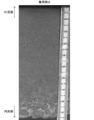
- FIG. 1 is a macrophotograph of a longitudinal cross section of a test material of Invention Example 9.
- FIG. 2 is a macroscopic photograph of a cross section of the test material of Comparative Example 4 in the longitudinal direction.
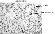
- FIG. 3 is a microstructure photograph at a position 20 mm from the outer peripheral side of the test material of the invention example 4.
- FIG. 4 is a microstructure photograph of a position 20 mm from the outer peripheral side of the test material of the inventive example 9.
- FIG. 5 is a microstructure photograph at a position of 20 mm from the outer peripheral side of the test material of Comparative Example 4.
- FIG. 6 is a photograph of a microstructure in the vicinity of the inner peripheral side of the test material of Comparative Example 4.
- the composite roll for rolling of the present invention can be constituted by an outer layer to be subjected to rolling, and an axial core material consisting of an intermediate layer and an inner layer, or an inner layer inside the outer layer.
- an inner layer material which comprises an inner layer the material which has toughness, such as high grade cast iron, ductile cast iron, graphite steel, can be illustrated, and an adamite material can be illustrated as an intermediate layer material which constitutes an intermediate layer.
- the outer layer can be produced, for example, by centrifugal casting.
- Centrifugal casting may be either vertical (the rotation axis is in the vertical direction), inclined (the rotation axis is in the oblique direction) or horizontal (the rotation axis is in the horizontal direction).
- the die rotation speed in centrifugal force casting is GNo. Is preferably 100 G or more.
- the outer layer can also be manufactured by static casting or the like, but centrifugal casting is preferable for reducing manufacturing costs.
- C 2.2% to 3.2% C crystallizes graphite to improve wear resistance and crack resistance, and can crystallize MC type carbide of high hardness to increase hardness.
- the content of C is 3.2% or less in order to reduce the crystallized graphite and cementite which is a eutectic carbide and to suppress the excessive crystallization of MC type carbide to improve the accident resistance as described later. I assume.
- the content of C is set to 2.2% or more. Preferably, it is 2.3% to 3.0%.
- Si 1.0% to 3.0%
- Si is an element necessary as a deoxidizer for the molten metal.
- centrifugal casting is also necessary to ensure the fluidity of the molten metal.
- Si is necessary as an element promoting graphite crystallization (partially precipitation). Therefore, it is contained 1.0% or more.
- the upper limit is made 3.0%. Preferably, it is 1.5% to 2.5%.
- Mn 0.3% to 2.0% Mn is an element necessary for enhancing the soundness of the molten metal as a desulfurizing agent for the molten metal or as a deoxidizing agent, and for strengthening the base structure. Therefore, it is contained 0.3% or more. However, if the content exceeds 2.0%, the mechanical properties deteriorate and the crack resistance decreases, so the content is made 2.0% or less.
- Ni 3.0% to 7.0%
- Ni is an element effective as an auxiliary element for graphitization and for improving the hardenability of the base to promote bainization and to strengthen the base. If the content is less than 3.0%, such effects are not sufficient, high hardness can not be obtained, and abrasion resistance becomes insufficient. Therefore, the lower limit is 3.0%.
- the upper limit is 7.0%. Preferably, it is 4.0% to 6.0%.
- Cr 0.5% to 2.5% Cr mainly bonds to C to form a solid solution in crystallized cementite, and contributes to the improvement of the wear resistance. In addition, some form precipitated carbides to strengthen the matrix. For this reason, 0.5% is contained. Cr is also contained in MC type carbides, and has the effect of lowering the crystallization temperature. As the temperature at which MC-type carbides crystallize decreases, crystallization of MC-type carbides can be delayed, and the viscosity of the MC-type carbides increases due to the temperature decrease of the molten metal. Movement in the melt is suppressed. This point is effective in suppressing the segregation of MC type carbides.
- the upper limit of Cr is 2 so that graphite can be crystallized even if a predetermined amount of V, which is a graphitization inhibiting element, is contained as in the case of Cr (V: 2.5% to 5.0%). .5%. Preferably, it is 0.8% to 1.5%.
- Mo 1.0% to 3.0% Mo is mainly bonded to C to form a solid solution in crystallized cementite, and contributes to the improvement of the wear resistance. In addition, a part thereof forms precipitated carbides and has an effect of strengthening the matrix, so that the content is 1.0% or more. However, if it exceeds 3.0%, crystallization and precipitation of graphite are inhibited, which causes the reduction in seizure resistance and the reduction in crack resistance as described above. Therefore, the upper limit is 3.0% or less. Preferably, it is 1.2% to 2.5%.
- V 2.5% to 5.0%
- V acts as a solid solution in the matrix to strengthen the matrix, and mainly bonds with C to form a high hardness MC-type carbide to improve the wear resistance of the outer layer. For this reason, V is added by 2.5% or more.
- MC type carbide mainly composed of V having a specific gravity smaller than that of the molten metal is formed, and segregates on the inner peripheral surface side of the outer layer at the time of centrifugal casting and is provided inside the outer layer.
- the upper limit is made 5.0% because the weldability with the inner layer and the intermediate layer is reduced. Preferably, it is 3.0% to 4.0%.
- Nb more than 0% and not more than 0.5%
- Nb is an element that combines with C to crystallize MC type carbides of extremely high hardness, so it is added over 0%.
- MC type carbide mainly composed of Nb has a specific gravity larger than that of a molten metal, for example, when the outer layer is produced by centrifugal casting, it segregates on the outer peripheral side. Therefore, in the present invention, as described later, since Nb% / V% ⁇ 0.1, the upper limit of Nb is set to 0.5% or less which is 1/10 of V. Preferably, it is 0.002% to 0.3%.
- the outer layer material of the present invention is essentially Fe as a remainder, and the inclusion of impurities inevitably mixed at the time of melting is acceptable as long as the properties of the cast iron material are not affected.
- both P and S lower the toughness of the material, it is preferable to be as small as possible, and it is more preferable to suppress both to 0.2% or less.
- the said outer layer component satisfies the following conditions other than each component range.
- This condition is to suppress the amount of MC-type carbide mainly composed of Nb, which has a crystallization temperature higher than that of a molten metal and is easily crystallized as a primary crystal, with V and Nb forming MC-type carbide to enhance wear resistance. It is a condition of MC-type carbide mainly composed of Nb crystallized as primary crystal is in a state where it can move easily in the unmelted molten metal and has a large specific gravity with respect to the molten metal, so it tends to cause segregation by centrifugal casting.
- the present outer layer material containing a large amount of carbide-forming elements in order to crystallize the graphite necessary for crack resistance, a large amount of C is contained as the content of the carbide-forming elements Cr, Mo, and V increases. You need to However, when forming the outer layer by centrifugal casting, if the amount of C is high, a large amount of MC type carbide having a difference in specific gravity from the molten metal crystallizes, which tends to cause segregation.
- the Cr content as described above and the condition (a) Nb% / V% ⁇ 0.1 allow the crystallization of the Nb-based MC-type carbide as a primary crystal by limiting the condition to (a)
- Nb solid-solve in MC type carbide mainly composed of V the specific gravity of MC type carbide mainly composed of V having a small specific gravity relative to the molten metal can be made close to the molten metal, MC type carbide Segregation can be prevented.
- V equivalent (V% + Nb% / 2) is set as a standard (coefficient 1.0), and C, Si, Cr And Mo amount respectively.
- C is 2.1 times the amount of V equivalent as a forming element of crystallized graphite and MC type carbide.
- Si is required as a graphite crystallization promoting element, it is set to 1.2 with respect to the V equivalent in order to secure the amount of graphite crystallization.
- Cr atomic weight: 52.0
- the coefficient of “-” is taken as the opposite effect of the carbide forming element of Since Mo (atomic weight: 95.94) has an atomic weight of about twice V and is less likely to form MC-type carbide than V, the coefficient for V equivalent is set to 0.5.
- the preferred upper limit of condition (b) is 12.5%.
- the outer layer can further contain W.
- W works in the same manner as Mo, but in the case of centrifugal casting, since it tends to form lamination segregation, it is preferable to be more than W: 0% and 3.0% or less. Preferably, it is 2.0% or less.
- the atomic weight of Mo is 95.94, and the atomic weight of W is 183.8, which is approximately twice that of Mo. Therefore, when converted to Mo equivalent, W needs twice as much as Mo. Therefore, in the present condition (b '), the Mo equivalent (Mo% + W% / 2) is set with respect to the condition (b).
- the upper limit of the condition (b ') is also preferably 12.5%.
- the outer layer preferably has an MC-type carbide area ratio of 4.0% to 11.0%. If the area ratio of MC type carbides is less than 4.0%, the outer layer may have an insufficient effect of improving the wear resistance. Moreover, it is because it is difficult to make the area ratio of MC type carbide more than 11.0% by coexistence relationship with graphite.
- the graphite area ratio of the outer layer it is preferable to adjust the graphite area ratio of the outer layer to 0.5% to 5.0%. If the area ratio of graphite is less than 0.5%, the effect of improving the seizure resistance of the outer layer is insufficient, and in the case of a throttling accident, cracks and seizure due to thermal shock occur. Since the seizure concentrates the load, the progress of the crack is significantly accelerated. By crystallizing graphite in the outer layer, it is possible to suppress the development of a crack that is generated by thermal shock in the case of a drawing accident, and it is possible to enhance the crack resistance of the outer layer.
- the amount of crystallized graphite can be adjusted by adding an inoculant such as Fe-Si or Ca-Si to the outer layer molten metal.
- an inoculant such as Fe-Si or Ca-Si
- the wear resistance and mechanical properties of the outer layer may be significantly reduced.
- the outer layer can further contain B.
- the content exceeds 0.1%, the mechanical properties significantly decrease, so the upper limit is made 0.1%. It is preferable to make it 0.05% or less.
- each outer layer material is a component which is not contained or a component which may be contained but which is not detectable is "-".
- Table 1 and Table 2 showing the measurement and test results, the components not satisfying the scope of the present invention, conditions, preferred measured values of the present invention, values outside the test results or values significantly inferior to the inventive examples Stars are added to enhance understanding visually.
- the outer layer material has the number of revolutions of the mold GNo. Is set to 100 G to 200 G, and the casting temperature is set to 1250.degree. C. to 1360.degree.
- the outer layer material has an outer diameter of 300 mm and a length of 200 mm, and an outer diameter of 570 mm to 800 mm and a length of 1100 mm to 2500 mm. Then, tempering was repeated several times at 400 ° C. to 600 ° C. for each outer layer material, and then a 200 mm ⁇ 200 mm sample was taken from each outer layer material.
- each sample material is polished using sandpaper of grain size 240, and after polishing for the range of the entire length in the longitudinal cross section
- the test material of (1) was subjected to an etching process of nitric acid aqueous solution, and a macrostructural photograph was taken.
- alumina buffing was performed on the test material, and a microstructure photograph was taken.
- FIG. 3 to 5 show 20 mm from the outer peripheral side in the longitudinal direction cross sections of invention example 4, invention example 9 and comparative example 4
- a microstructure photograph and a microstructure photograph in the vicinity of the inner peripheral side in the longitudinal direction cross section of Comparative Example 4 are shown in FIG. Since MC-type carbide is hard, it protrudes more than other carbides when alumina buffing is performed, and in the photograph of its structure, the shadow of the protruding MC-type carbide is photographed. Also, in the microstructure photograph, the black mass is graphite.
- the comparative examples 1 to 5 were evaluated as “2 (present)".
- the evaluation was "2 (present)", even though the V and Nb concentrations for forming MC-type carbides are appropriate, these Comparative Examples This is because the amount with respect to the C concentration and the Cr concentration does not satisfy the condition (b), and the MC-type carbide crystallized excessively is segregated.
- Comparative Example 2 and Comparative Example 5 although the component range of each element is included in the scope of the present invention, it is found that segregation of MC type carbides is caused by not satisfying the condition (b).
- Comparative Example 3 the amount of V is large, and the MC type carbide which is lightweight with respect to the specific gravity of the molten metal crystallizes to cause segregation.
- Comparative Example 4 has a small amount of V but a large amount of Nb, and does not satisfy not only the condition (b) but also the condition (a). It is because out segregation occurred.
- ⁇ Seize load (N)> The seizing load was measured by a high-speed Falex-type wear tester (manufactured by Kobe Steel, product name: high-speed Falex-type friction tester). In the test, a cylindrical test piece (diameter 10 mm, length 35 mm) is taken from each test material, and while rotating the test piece at 200 rpm, it is sandwiched by two V blocks made of SUS430, and the load is increased While loading at 100 N / sec, raise the load to 1500 N at a speed of 15 N / 9 seconds. The inflection point of the torque during this time was evaluated as the seizure load. The higher the seizure load, the better the seizure resistance.
- any of the inventive examples it is possible to suppress welding abnormality with the axial core material by not showing segregation of MC type carbide, and to improve the accident resistance as a composite roll for rolling I understand. Further, since the graphite area ratio and the MC type carbide area ratio are respectively adjusted to the desired ranges, it is understood that the outer layer of the composite roll for rolling is also extremely good in the seizure load and the wear amount.
- the composite roll for rolling of the present invention since the outer layer is excellent in wear resistance, crack resistance and accident resistance, the service life of the roll can be extended, thereby reducing the cost of the roll. Furthermore, it contributes to the stabilization of roll inventory management.
- the composite roll for rolling according to the present invention is particularly suitable for application to the latter stage stand of hot finish rolling where the operation stability is required.
Landscapes
- Chemical & Material Sciences (AREA)
- Engineering & Computer Science (AREA)
- Mechanical Engineering (AREA)
- Materials Engineering (AREA)
- Metallurgy (AREA)
- Organic Chemistry (AREA)
- Physics & Mathematics (AREA)
- Geometry (AREA)
- Reduction Rolling/Reduction Stand/Operation Of Reduction Machine (AREA)
Abstract
Description
外層を有する遠心力鋳造製圧延用複合ロールであって、
前記外層は、質量%にて、C:2.2%~3.2%、Si:1.0%~3.0%、Mn:0.3%~2.0%、Ni:3.0%~7.0%、Cr:0.5%~2.5%、Mo:1.0%~3.0%、V:2.5%~5.0%、Nb:0%を越えて0.5%以下、残部Fe及び不可避的不純物であって、
条件(a):Nb%/V%<0.1、
条件(b):2.1×C%+1.2×Si%-Cr%+0.5×Mo%+(V%+Nb%/2)≦13.0%
を満足する。
外層を有する遠心力鋳造製圧延用複合ロールであって、
前記外層は、質量%にて、C:2.2%~3.2%、Si:1.0%~3.0%、Mn:0.3%~2.0%、Ni:3.0%~7.0%、Cr:0.5%~2.5%、Mo:1.0%~3.0%、W:0%を越えて3.0%以下、V:2.5%~5.0%、Nb:0%を越えて0.5%以下、残部Fe及び不可避的不純物であって、
条件(a):Nb%/V%<0.1、
条件(b’):2.1×C%+1.2×Si%-Cr%+0.5×(Mo%+W%/2)+(V%+Nb%/2)≦13.0%
を満足する。
本発明の圧延用複合ロールの外層材の成分限定理由を説明する。なお、以下において、特に明示しない場合、「%」は、質量%である。
Cは、黒鉛を晶出させ、耐摩耗性や耐クラック性を改善させると共に、高硬度のMC型炭化物を晶出させて硬度を高めることができる。晶出する黒鉛及び共晶炭化物であるセメンタイトを減少させ、後述するようにMC型炭化物の過剰な晶出を抑制して耐事故性を向上させるために、Cの含有量は3.2%以下とする。一方で、黒鉛の晶出量を確保するために、Cの含有量は2.2%以上とする。好ましくは、2.3%~3.0%である。
Siは、溶湯の脱酸剤として必要な元素である。とくに、遠心力鋳造では、湯流れ性の確保のためにも必要である。また、高合金グレン鋳鉄材の場合、Siは、黒鉛晶出(一部は析出)の促進元素として必要である。従って、1.0%以上含有させる。しかし、3.0%を超えると機械的性質が劣化して耐クラック性低下の原因となるため、上限は3.0%とする。好ましくは、1.5%~2.5%である。
Mnは、溶湯の脱硫剤としてあるいは脱酸剤として溶湯の健全性を向上させるため、および基地組織の強化に必要な元素である。従って、0.3%以上含有させる。しかし、2.0%を超えて含有すると、機械的性質が劣化して耐クラック性が低下するため、2.0%以下とする。
Niは、黒鉛晶出の補助元素として、また基地の焼入れ性を改善してベイナイト化を促進し、基地強化を図るのに有効な元素である。3.0%未満ではこのような効果が十分ではなく、高硬度が得られず、耐摩耗性が不十分となる。このため、下限は3.0%とする。一方、7.0%を超えて含まれると残留オーステナイト量が多くなり、熱間圧延中に残留オーステナイトが分解して耐肌荒れ性が低下する。従って、上限は7.0%とする。好ましくは、4.0%~6.0%である。
Crは、主としてCと結合して晶出セメンタイト中に固溶し、耐摩耗性の向上に寄与する。また、一部は析出炭化物を形成して、基地を強化する。このため、0.5%含有させる。なお、Crは、MC型炭化物にも含まれ、その晶出温度を低下させる作用がある。MC型炭化物が晶出する温度が低下することで、MC型炭化物の晶出を遅らせることができ、MC型炭化物の晶出時に溶湯の温度低下によりその粘性が高まっているため、MC型炭化物の溶湯中での移動が抑制される。この点でMC型炭化物の偏析を抑制する効果がある。一方、Crは、非常に強い黒鉛化阻害元素であるため、黒鉛の晶出及び析出が阻害され、摩擦係数が増大し、耐焼付き性も低下する。これにより、圧延材の通板性が損なわれてロール表面に圧延材が焼付いたり、脆化して、耐クラック性低下の原因となる。従って、Crと同様に黒鉛化阻害元素であるVを所定量含有させても(V:2.5%~5.0%)、黒鉛を晶出させることができるように、Crの上限は2.5%とする。好ましくは、0.8%~1.5%である。
Moは、主としてCと結合して晶出セメンタイト中に固溶し、耐摩耗性の向上に寄与する。また、一部は析出炭化物を形成して、基地を強化する作用を有するため、1.0%以上含有させる。しかし、3.0%を越えると、黒鉛の晶出及び析出が阻害され、上記と同様、耐焼付き性低下や耐クラック性低下の原因となる。従って、上限は3.0%以下とする。好ましくは、1.2%~2.5%である。
Vは、基地に固溶して基地を強化する作用があり、さらに、主としてCと結合し、高硬度のMC型炭化物を形成し、外層の耐摩耗性を改善させる。このため、Vは2.5%以上添加する。一方で、Vの添加量が多くなると、溶湯に比べて比重の小さいVを主体とするMC型炭化物が形成されて、遠心力鋳造時に外層の内周面側に偏析し、外層の内側に設けられる内層や中間層との溶着性を低下させるから、上限を5.0%とする。好ましくは、3.0%~4.0%である。
Nbは、Cと結合して極めて高硬度のMC型炭化物を晶出する元素であるため、0%を越えて添加する。一方、Nbを主体とするMC型炭化物は、溶湯に比べて比重が大きいため、たとえば遠心力鋳造により外層を作製した場合、外周側に偏析してしまう。このため、本発明では、後述のとおり、Nb%/V%<0.1に制限しているから、Nbの上限は、Vの1/10である0.5%以下とする。好ましくは、0.002%~0.3%である。
本外層材は、残部実質的にFeであり、溶製時に不可避的に混入する不純物は鋳鉄材の特性に影響を及ぼさない範囲でその含有は許容される。なお、P、Sはいずれも材質の靱性を低下させるため、少ない程好ましく、両者とも0.2%以下に抑えることがより好ましい。
本条件は、耐摩耗性を高めるためのMC型炭化物を形成するVとNbにおいて、溶湯よりも晶出温度が高く初晶として晶出しやすいNbを主体とするMC型炭化物の量を抑制するための条件である。初晶として晶出したNbを主体とするMC型炭化物は、凝固が進んでいない溶湯内で移動しやすい状態にあり、且つ溶湯に対して比重が大きいため、遠心力鋳造により偏析を起こしやすい。特に、炭化物形成元素の多い本外層材において、耐クラック性に必要な黒鉛を晶出させるためには、炭化物形成元素であるCr,Mo,Vの含有量の増加に伴って、Cを多く含有させる必要がある。しかし、遠心力鋳造により外層を形成する場合、C量が高いと溶湯との比重差のあるMC型炭化物が多量に晶出し、偏析を招きやすい。そこで本発明では、上記のように低Cr量にすると共に、条件(a)Nb%/V%<0.1に制限することで、Nbを主体とするMC型炭化物の初晶としての晶出を抑え、且つVを主体とするMC型炭化物中にNbを固溶させることで、溶湯に対して比重の小さいVを主体とするMC型炭化物の比重を溶湯に近づけることができ、MC型炭化物の偏析を防止することができる。

MC型炭化物の偏析は、得られたマクロ組織写真に基づいて評価した。図1及び図2を参照すると、図1(発明例9)は、供試材の長手方向断面にMC型炭化物の偏析は認められない。一方、図2(比較例4)では、供試材の内周側、すなわち、図2の下側に濃く腐食された領域が認められる。これは、MC型炭化物が偏析したものである。比較例4の長手方向断面における外周側と内周側のミクロ組織写真(図5及び図6)を参照すると、図5の外周側はMC型炭化物が疎であるのに対し、図6の内周側はMC型炭化物が密であることからも、比較例4にMC型炭化物が内周側に偏析していることがわかる。これは、溶湯比重に対して軽量なMC型炭化物が過剰に晶出し、遠心力鋳造の際にその比重差によって内側に凝集したためである。比較例4のように、外層材の内周側にMC型炭化物が偏析すると、その内側に中間層や内層などの軸芯材を鋳込んだ場合でも偏析層は再溶解し難いから、境界に残存して溶着異常を起こし、耐事故性を低下させるため、圧延用複合ロールの外層として適さない。なお、図1に示す発明例9の供試材についても、内周側約20mmの範囲に内周側とは異なる組織が観察されるが、この層は比較的低融点の最終凝固層であるため、一部引け巣を伴うが、軸芯材を鋳込んだ際に再溶解して、健全に溶着するため問題はない。

次に、得られた供試材について、長手方向断面の外周側のミクロ組織を上記と同様の要領で写真撮影し、黒鉛量を黒鉛面積率として測定した。なお、以降の測定、試験から、MC型炭化物の偏析が確認された比較例1、比較例2及び比較例5は除外した。
供試材の内周側のミクロ組織写真(たとえば図3乃至図5参照)から、MC型炭化物量をMC型炭化物面積率により測定した。結果を表2「MC型炭化物面積率」に示す。表2を参照すると、発明例は、何れもMC型炭化物量が4.0%~11.0%の範囲に調整できており、すぐれた耐摩耗性を有していることがわかる。一方、比較例4、比較例7乃至比較例9はMC型炭化物面積率が4.0%未満であることから、耐摩耗性の点で劣ることがわかる。
焼付き荷重は、高速ファレックス型摩耗試験機(神鋼造機製、製品名:高速ファレックス型摩擦試験機)にて測定した。試験は、各供試材から円柱状の試験片(直径10mm、長さ35mm)を採取し、供試片を200rpmで回転させながら、SUS430製の2個のVブロックで挟み、荷重を上昇速度100N/secで負荷しつつ、15N/9秒の速度で荷重が1500Nに達するまで上昇させる。この間におけるトルクの変曲点を焼付き荷重として評価した。焼付き荷重が高い程、耐焼付き性が良い。試験結果を表2「焼付き荷重」に示す。表2を参照すると、発明例は何れも焼付き荷重が高く、比較例に比して十分な耐焼付き性を具備していることがわかる。一方、比較例4、比較例7、比較例9は焼付き荷重が十分でなく、耐焼付き性に劣ることがわかる。
摩耗量は、上記の高速ファレックス型摩耗試験機にて測定した。試験は、各供試材から円柱状の試験片(直径10mm、長さ35mm)を採取し、供試片を200rpmで回転させながら、SS400製の2個のVブロックで挟み、荷重を上昇速度100N/secで負荷しつつ、荷重が1000Nに達した時点で30分間荷重を保持することにより行なった。試験後、試験片とVブロックの接触面の摩耗量を測定した。結果を表2「摩耗量」に示す。表2を参照すると、発明例は何れも摩耗量を小さく抑えられており、十分な耐摩耗性を具備していることがわかる。一方、比較例4、比較例7乃至比較例9は摩耗量が大きく、耐摩耗性に劣ることがわかる。これは、耐摩耗性の向上に必要なMC型炭化物量が面積率で4.0%未満であるためである。
上記各測定、試験結果を参照すると、発明例は何れもMC型炭化物の偏析が見られないことで軸芯材との溶着異常を抑えることができ、圧延用複合ロールとして耐事故性を向上できることがわかる。また、黒鉛面積率及びMC型炭化物面積率が夫々所望の範囲に調整されていることから、焼付き荷重、摩耗量においても圧延用複合ロールの外層として極めて良好であることがわかる。
Claims (5)
- 外層を有する遠心力鋳造製圧延用複合ロールであって、
前記外層は、質量%にて、C:2.2%~3.2%、Si:1.0%~3.0%、Mn:0.3%~2.0%、Ni:3.0%~7.0%、Cr:0.5%~2.5%、Mo:1.0%~3.0%、V:2.5%~5.0%、Nb:0%を越えて0.5%以下、残部Fe及び不可避的不純物であって、
条件(a):Nb%/V%<0.1、
条件(b):2.1×C%+1.2×Si%-Cr%+0.5×Mo%+(V%+Nb%/2)≦13.0%
を満足する、ことを特徴とする圧延用複合ロール。 - 外層を有する遠心力鋳造製圧延用複合ロールであって、
前記外層は、質量%にて、C:2.2%~3.2%、Si:1.0%~3.0%、Mn:0.3%~2.0%、Ni:3.0%~7.0%、Cr:0.5%~2.5%、Mo:1.0%~3.0%、W:0%を越えて3.0%以下、V:2.5%~5.0%、Nb:0%を越えて0.5%以下、残部Fe及び不可避的不純物であって、
条件(a):Nb%/V%<0.1、
条件(b’):2.1×C%+1.2×Si%-Cr%+0.5×(Mo%+W%/2)+(V%+Nb%/2)≦13.0%
を満足する、ことを特徴とする圧延用複合ロール。 - 前記外層は、さらに、質量%にて、B:0%を越えて0.1%以下を含有する、
請求項1又は請求項2に記載の圧延用複合ロール。 - 前記外層は、黒鉛面積率が0.5%~5.0%である、
請求項1乃至請求項3の何れかに記載の圧延用複合ロール。 - 前記外層は、MC型炭化物面積率が4.0%~11.0%である、
請求項1乃至請求項4の何れかに記載の圧延用複合ロール。
Priority Applications (5)
| Application Number | Priority Date | Filing Date | Title |
|---|---|---|---|
| BR112019012904A BR112019012904A2 (pt) | 2016-12-28 | 2017-12-26 | rolo compósito para laminação |
| EP17887782.5A EP3563942A4 (en) | 2016-12-28 | 2017-12-26 | COMPOSITE ROLLER FOR ROLLING |
| KR1020197018513A KR102215460B1 (ko) | 2016-12-28 | 2017-12-26 | 압연용 복합 롤 |
| CN201780081602.6A CN110114155B (zh) | 2016-12-28 | 2017-12-26 | 轧制用复合辊 |
| US16/466,398 US10947611B2 (en) | 2016-12-28 | 2017-12-26 | Composite roll for rolling |
Applications Claiming Priority (2)
| Application Number | Priority Date | Filing Date | Title |
|---|---|---|---|
| JP2016-254908 | 2016-12-28 | ||
| JP2016254908A JP6313844B1 (ja) | 2016-12-28 | 2016-12-28 | 圧延用複合ロール |
Publications (1)
| Publication Number | Publication Date |
|---|---|
| WO2018124101A1 true WO2018124101A1 (ja) | 2018-07-05 |
Family
ID=61968289
Family Applications (1)
| Application Number | Title | Priority Date | Filing Date |
|---|---|---|---|
| PCT/JP2017/046720 WO2018124101A1 (ja) | 2016-12-28 | 2017-12-26 | 圧延用複合ロール |
Country Status (7)
| Country | Link |
|---|---|
| US (1) | US10947611B2 (ja) |
| EP (1) | EP3563942A4 (ja) |
| JP (1) | JP6313844B1 (ja) |
| KR (1) | KR102215460B1 (ja) |
| CN (1) | CN110114155B (ja) |
| BR (1) | BR112019012904A2 (ja) |
| WO (1) | WO2018124101A1 (ja) |
Families Citing this family (3)
| Publication number | Priority date | Publication date | Assignee | Title |
|---|---|---|---|---|
| WO2020203570A1 (ja) | 2019-04-03 | 2020-10-08 | 日鉄ロールズ株式会社 | 遠心鋳造製圧延用複合ロール及びその製造方法 |
| WO2020203571A1 (ja) * | 2019-04-03 | 2020-10-08 | 日鉄ロールズ株式会社 | 遠心鋳造製圧延用複合ロール及びその製造方法 |
| CN111168030B (zh) * | 2020-02-04 | 2021-06-25 | 三鑫重工机械有限公司 | 一种含石墨的贝氏体半钢板带粗轧工作辊 |
Citations (4)
| Publication number | Priority date | Publication date | Assignee | Title |
|---|---|---|---|---|
| JPH05311335A (ja) * | 1992-05-12 | 1993-11-22 | Kawasaki Steel Corp | スリーブロール |
| JPH06256889A (ja) | 1993-03-05 | 1994-09-13 | Kubota Corp | 黒鉛を有するハイス系鋳鉄材及び複合ロール |
| JP2004082209A (ja) * | 2002-06-24 | 2004-03-18 | Nippon Steel Corp | 遠心鋳造製熱間圧延用複合ロール |
| WO2014178437A1 (ja) * | 2013-05-02 | 2014-11-06 | 日立金属株式会社 | 遠心鋳造製熱間圧延用複合ロール |
Family Cites Families (19)
| Publication number | Priority date | Publication date | Assignee | Title |
|---|---|---|---|---|
| JPS63224859A (ja) | 1987-03-16 | 1988-09-19 | Kawasaki Steel Corp | 遠心鋳造複合ロ−ルの製造方法 |
| JP2841276B2 (ja) * | 1994-06-29 | 1998-12-24 | 川崎製鉄株式会社 | 熱間圧延用ロール外層材及び熱間圧延用ロールの製造方法 |
| AT408666B (de) | 1999-04-22 | 2002-02-25 | Weinberger Eisenwerk | Gusswerkstoff und verfahren zu dessen herstellung |
| JP3412590B2 (ja) * | 2000-01-17 | 2003-06-03 | 関東特殊製鋼株式会社 | 圧延用ロール |
| JP4123912B2 (ja) | 2001-11-28 | 2008-07-23 | Jfeスチール株式会社 | 熱間圧延用ロール外層材および熱間圧延用複合ロール |
| JP4428214B2 (ja) | 2004-11-30 | 2010-03-10 | Jfeスチール株式会社 | 熱間圧延用高Cr系ロール外層材および熱間圧延用高Cr系複合ロール |
| JP4778863B2 (ja) * | 2006-08-28 | 2011-09-21 | 日鉄住金ロールズ株式会社 | 遠心鋳造製圧延用複合ロ−ルの外層材 |
| JP5136138B2 (ja) | 2008-03-18 | 2013-02-06 | Jfeスチール株式会社 | 熱間圧延用遠心鋳造製複合ロール |
| CN102333124A (zh) * | 2011-10-09 | 2012-01-25 | 华为技术有限公司 | 一种提升云计算模式下语音或视频传输质量的方法及装置 |
| IN2014MN00580A (ja) | 2011-10-19 | 2015-07-03 | Jfe Steel Corp | |
| ES2562625T3 (es) | 2011-11-21 | 2016-03-07 | Hitachi Metals, Ltd. | Rodillo compuesto fundido centrífugamente y su método de producción |
| EP2740552B1 (en) * | 2012-04-02 | 2016-03-09 | Hitachi Metals, Ltd. | Centrifugally cast composite roller and method for manufacturing same |
| JP5862526B2 (ja) * | 2012-09-13 | 2016-02-16 | Jfeスチール株式会社 | 熱間圧延用ロール外層材および熱間圧延用複合ロール |
| WO2015045985A1 (ja) * | 2013-09-25 | 2015-04-02 | 日立金属株式会社 | 遠心鋳造製熱間圧延用複合ロール |
| KR102219332B1 (ko) * | 2013-09-25 | 2021-02-22 | 히타치 긴조쿠 가부시키가이샤 | 원심 주조제 복합 롤 및 그 제조 방법 |
| JP2015080813A (ja) | 2013-10-24 | 2015-04-27 | 日鉄住金ロールズ株式会社 | 遠心鋳造製圧延用複合ロール |
| JP6028282B2 (ja) * | 2014-08-25 | 2016-11-16 | 株式会社クボタ | 圧延用複合ロールの外層材及び圧延用複合ロール |
| EP3437747B1 (en) * | 2016-03-31 | 2020-11-25 | Hitachi Metals, Ltd. | Composite roll for rolling |
| BR112019013893B1 (pt) * | 2017-02-08 | 2023-03-28 | Hitachi Metals, Ltd | Rolo compósito para laminação e seu método de produção |
-
2016
- 2016-12-28 JP JP2016254908A patent/JP6313844B1/ja not_active Expired - Fee Related
-
2017
- 2017-12-26 US US16/466,398 patent/US10947611B2/en active Active
- 2017-12-26 CN CN201780081602.6A patent/CN110114155B/zh not_active Expired - Fee Related
- 2017-12-26 WO PCT/JP2017/046720 patent/WO2018124101A1/ja unknown
- 2017-12-26 BR BR112019012904A patent/BR112019012904A2/pt active Search and Examination
- 2017-12-26 EP EP17887782.5A patent/EP3563942A4/en not_active Withdrawn
- 2017-12-26 KR KR1020197018513A patent/KR102215460B1/ko active IP Right Grant
Patent Citations (4)
| Publication number | Priority date | Publication date | Assignee | Title |
|---|---|---|---|---|
| JPH05311335A (ja) * | 1992-05-12 | 1993-11-22 | Kawasaki Steel Corp | スリーブロール |
| JPH06256889A (ja) | 1993-03-05 | 1994-09-13 | Kubota Corp | 黒鉛を有するハイス系鋳鉄材及び複合ロール |
| JP2004082209A (ja) * | 2002-06-24 | 2004-03-18 | Nippon Steel Corp | 遠心鋳造製熱間圧延用複合ロール |
| WO2014178437A1 (ja) * | 2013-05-02 | 2014-11-06 | 日立金属株式会社 | 遠心鋳造製熱間圧延用複合ロール |
Non-Patent Citations (1)
| Title |
|---|
| See also references of EP3563942A4 * |
Also Published As
| Publication number | Publication date |
|---|---|
| JP6313844B1 (ja) | 2018-04-18 |
| CN110114155B (zh) | 2021-02-05 |
| US20190352753A1 (en) | 2019-11-21 |
| KR20190100210A (ko) | 2019-08-28 |
| US10947611B2 (en) | 2021-03-16 |
| EP3563942A4 (en) | 2020-07-29 |
| JP2018103245A (ja) | 2018-07-05 |
| EP3563942A1 (en) | 2019-11-06 |
| BR112019012904A2 (pt) | 2019-12-31 |
| KR102215460B1 (ko) | 2021-02-15 |
| CN110114155A (zh) | 2019-08-09 |
Similar Documents
| Publication | Publication Date | Title |
|---|---|---|
| JP5950048B2 (ja) | 遠心鋳造製熱間圧延用複合ロール | |
| JP5136138B2 (ja) | 熱間圧延用遠心鋳造製複合ロール | |
| WO2018124101A1 (ja) | 圧延用複合ロール | |
| JP4483585B2 (ja) | 熱間圧延用ロール外層材および熱間圧延用複合ロール | |
| JP5703718B2 (ja) | 熱間圧延用遠心鋳造製ロール外層材および複合ロール | |
| JP6515957B2 (ja) | 耐摩耗性に優れた圧延用ロール外層材および圧延用複合ロール | |
| JP5434276B2 (ja) | 熱間圧延用遠心鋳造製複合ロール | |
| JP2016180167A (ja) | 連続鋳掛け肉盛鋳造製圧延用複合ロール | |
| JP6292362B1 (ja) | 熱間圧延用ロール外層材および熱間圧延用複合ロール | |
| JP5516545B2 (ja) | 耐疲労性に優れた熱間圧延用遠心鋳造製ロール外層材および熱間圧延用遠心鋳造製複合ロール | |
| JP7396256B2 (ja) | 圧延用ロール外層材及び圧延用複合ロール | |
| JP5447812B2 (ja) | 熱間圧延用遠心鋳造製複合ロール | |
| JP5434249B2 (ja) | 熱間圧延用遠心鋳造製複合ロール | |
| JP6840696B2 (ja) | 圧延用複合ロール | |
| JP6518314B2 (ja) | 圧延用複合ロール | |
| JP5867143B2 (ja) | 耐疲労性に優れた熱間圧延用遠心鋳造製ロール外層材および熱間圧延用遠心鋳造製複合ロール、ならびにそれらの製造方法 | |
| JP5327342B2 (ja) | 耐疲労性に優れた熱間圧延用遠心鋳造製ロール外層材および熱間圧延用遠心鋳造製複合ロール | |
| JP4569122B2 (ja) | 熱間圧延用ロール外層材および熱間圧延用複合ロール | |
| JP2018161655A (ja) | 熱間圧延用ロール外層材および熱間圧延用複合ロール | |
| JP7136037B2 (ja) | 熱間圧延用ロール外層材および熱間圧延用複合ロール | |
| JP4059099B2 (ja) | 継目無鋼管圧延用鋳造ロール材および継目無鋼管圧延用ロール | |
| JP5867144B2 (ja) | 耐疲労性に優れた熱間圧延用遠心鋳造製ロール外層材および熱間圧延用遠心鋳造製複合ロール、ならびにそれらの製造方法 | |
| KR20210082226A (ko) | 열간 압연용 롤 외층재 및 열간 압연용 복합 롤 |
Legal Events
| Date | Code | Title | Description |
|---|---|---|---|
| 121 | Ep: the epo has been informed by wipo that ep was designated in this application |
Ref document number: 17887782 Country of ref document: EP Kind code of ref document: A1 |
|
| ENP | Entry into the national phase |
Ref document number: 20197018513 Country of ref document: KR Kind code of ref document: A |
|
| NENP | Non-entry into the national phase |
Ref country code: DE |
|
| REG | Reference to national code |
Ref country code: BR Ref legal event code: B01A Ref document number: 112019012904 Country of ref document: BR |
|
| ENP | Entry into the national phase |
Ref document number: 2017887782 Country of ref document: EP Effective date: 20190729 |
|
| ENP | Entry into the national phase |
Ref document number: 112019012904 Country of ref document: BR Kind code of ref document: A2 Effective date: 20190621 |