WO2018117276A1 - Compresseur à vis - Google Patents
Compresseur à vis Download PDFInfo
- Publication number
- WO2018117276A1 WO2018117276A1 PCT/JP2018/006146 JP2018006146W WO2018117276A1 WO 2018117276 A1 WO2018117276 A1 WO 2018117276A1 JP 2018006146 W JP2018006146 W JP 2018006146W WO 2018117276 A1 WO2018117276 A1 WO 2018117276A1
- Authority
- WO
- WIPO (PCT)
- Prior art keywords
- discharge
- shaft
- screw compressor
- seal ring
- shaft hole
- Prior art date
Links
Images

Classifications
-
- F—MECHANICAL ENGINEERING; LIGHTING; HEATING; WEAPONS; BLASTING
- F04—POSITIVE - DISPLACEMENT MACHINES FOR LIQUIDS; PUMPS FOR LIQUIDS OR ELASTIC FLUIDS
- F04C—ROTARY-PISTON, OR OSCILLATING-PISTON, POSITIVE-DISPLACEMENT MACHINES FOR LIQUIDS; ROTARY-PISTON, OR OSCILLATING-PISTON, POSITIVE-DISPLACEMENT PUMPS
- F04C18/00—Rotary-piston pumps specially adapted for elastic fluids
- F04C18/08—Rotary-piston pumps specially adapted for elastic fluids of intermeshing-engagement type, i.e. with engagement of co-operating members similar to that of toothed gearing
- F04C18/12—Rotary-piston pumps specially adapted for elastic fluids of intermeshing-engagement type, i.e. with engagement of co-operating members similar to that of toothed gearing of other than internal-axis type
- F04C18/14—Rotary-piston pumps specially adapted for elastic fluids of intermeshing-engagement type, i.e. with engagement of co-operating members similar to that of toothed gearing of other than internal-axis type with toothed rotary pistons
- F04C18/16—Rotary-piston pumps specially adapted for elastic fluids of intermeshing-engagement type, i.e. with engagement of co-operating members similar to that of toothed gearing of other than internal-axis type with toothed rotary pistons with helical teeth, e.g. chevron-shaped, screw type
-
- F—MECHANICAL ENGINEERING; LIGHTING; HEATING; WEAPONS; BLASTING
- F04—POSITIVE - DISPLACEMENT MACHINES FOR LIQUIDS; PUMPS FOR LIQUIDS OR ELASTIC FLUIDS
- F04C—ROTARY-PISTON, OR OSCILLATING-PISTON, POSITIVE-DISPLACEMENT MACHINES FOR LIQUIDS; ROTARY-PISTON, OR OSCILLATING-PISTON, POSITIVE-DISPLACEMENT PUMPS
- F04C27/00—Sealing arrangements in rotary-piston pumps specially adapted for elastic fluids
- F04C27/005—Axial sealings for working fluid
-
- F—MECHANICAL ENGINEERING; LIGHTING; HEATING; WEAPONS; BLASTING
- F04—POSITIVE - DISPLACEMENT MACHINES FOR LIQUIDS; PUMPS FOR LIQUIDS OR ELASTIC FLUIDS
- F04C—ROTARY-PISTON, OR OSCILLATING-PISTON, POSITIVE-DISPLACEMENT MACHINES FOR LIQUIDS; ROTARY-PISTON, OR OSCILLATING-PISTON, POSITIVE-DISPLACEMENT PUMPS
- F04C27/00—Sealing arrangements in rotary-piston pumps specially adapted for elastic fluids
- F04C27/008—Sealing arrangements in rotary-piston pumps specially adapted for elastic fluids for other than working fluid, i.e. the sealing arrangements are not between working chambers of the machine
- F04C27/009—Shaft sealings specially adapted for pumps
-
- F—MECHANICAL ENGINEERING; LIGHTING; HEATING; WEAPONS; BLASTING
- F04—POSITIVE - DISPLACEMENT MACHINES FOR LIQUIDS; PUMPS FOR LIQUIDS OR ELASTIC FLUIDS
- F04C—ROTARY-PISTON, OR OSCILLATING-PISTON, POSITIVE-DISPLACEMENT MACHINES FOR LIQUIDS; ROTARY-PISTON, OR OSCILLATING-PISTON, POSITIVE-DISPLACEMENT PUMPS
- F04C29/00—Component parts, details or accessories of pumps or pumping installations, not provided for in groups F04C18/00 - F04C28/00
- F04C29/02—Lubrication; Lubricant separation
- F04C29/026—Lubricant separation
-
- F—MECHANICAL ENGINEERING; LIGHTING; HEATING; WEAPONS; BLASTING
- F04—POSITIVE - DISPLACEMENT MACHINES FOR LIQUIDS; PUMPS FOR LIQUIDS OR ELASTIC FLUIDS
- F04C—ROTARY-PISTON, OR OSCILLATING-PISTON, POSITIVE-DISPLACEMENT MACHINES FOR LIQUIDS; ROTARY-PISTON, OR OSCILLATING-PISTON, POSITIVE-DISPLACEMENT PUMPS
- F04C29/00—Component parts, details or accessories of pumps or pumping installations, not provided for in groups F04C18/00 - F04C28/00
- F04C29/02—Lubrication; Lubricant separation
- F04C29/028—Means for improving or restricting lubricant flow
-
- F—MECHANICAL ENGINEERING; LIGHTING; HEATING; WEAPONS; BLASTING
- F16—ENGINEERING ELEMENTS AND UNITS; GENERAL MEASURES FOR PRODUCING AND MAINTAINING EFFECTIVE FUNCTIONING OF MACHINES OR INSTALLATIONS; THERMAL INSULATION IN GENERAL
- F16J—PISTONS; CYLINDERS; SEALINGS
- F16J15/00—Sealings
- F16J15/16—Sealings between relatively-moving surfaces
- F16J15/18—Sealings between relatively-moving surfaces with stuffing-boxes for elastic or plastic packings
-
- F—MECHANICAL ENGINEERING; LIGHTING; HEATING; WEAPONS; BLASTING
- F16—ENGINEERING ELEMENTS AND UNITS; GENERAL MEASURES FOR PRODUCING AND MAINTAINING EFFECTIVE FUNCTIONING OF MACHINES OR INSTALLATIONS; THERMAL INSULATION IN GENERAL
- F16J—PISTONS; CYLINDERS; SEALINGS
- F16J15/00—Sealings
- F16J15/46—Sealings with packing ring expanded or pressed into place by fluid pressure, e.g. inflatable packings
- F16J15/48—Sealings with packing ring expanded or pressed into place by fluid pressure, e.g. inflatable packings influenced by the pressure within the member to be sealed
-
- F—MECHANICAL ENGINEERING; LIGHTING; HEATING; WEAPONS; BLASTING
- F04—POSITIVE - DISPLACEMENT MACHINES FOR LIQUIDS; PUMPS FOR LIQUIDS OR ELASTIC FLUIDS
- F04C—ROTARY-PISTON, OR OSCILLATING-PISTON, POSITIVE-DISPLACEMENT MACHINES FOR LIQUIDS; ROTARY-PISTON, OR OSCILLATING-PISTON, POSITIVE-DISPLACEMENT PUMPS
- F04C2240/00—Components
- F04C2240/30—Casings or housings
Definitions
- the present invention relates to a screw compressor, and more particularly to a screw compressor that performs shaft sealing using a seal ring.
- Patent Document 1 A technique related to shaft sealing by a seal ring in a screw compressor is described in Patent Document 1, for example.
- an annular groove is provided in an intermediate portion of a shaft portion (shaft portion) on the discharge side of the screw rotor, and a seal ring is disposed in the annular groove.
- the outer peripheral surface of the seal ring is brought into contact with the inner surface of the shaft hole of the casing, and one end surface (axial side surface) of the seal ring is brought into contact with one groove wall of the annular groove by the pressure in the outlet region of the compressed working medium. By contacting, the gap between the shaft portion and the shaft hole is sealed.
- a plurality of compression chambers defined by a screw rotor having a plurality of spiral lobes and a casing housing the screw rotor are contracted while moving in the axial direction along with the rotation of the screw rotor.
- the working fluid in the compression chamber is compressed. Due to such a compression principle, the pressure of the working fluid in the vicinity of the discharge-side end face of the screw rotor varies depending on the position in the rotation direction (circumferential direction) of each compression chamber. That is, a pressure distribution exists in the circumferential direction in the working fluid near the discharge side end face.
- the working fluid Due to the circumferential pressure distribution of the working fluid, the working fluid leaking into the gap between the discharge-side shaft portion of the screw rotor and the discharge-side shaft hole of the casing (discharge-side shaft hole gap) in the circumferential direction. A pressure distribution occurs. Therefore, in the relatively high pressure region, the working fluid leaks toward the outside of the compressor, but in the relatively low pressure region, the leakage flow rate of the working fluid is less than the high pressure region. On the contrary, external fluid flows into the compression chamber.
- the present invention has been made to solve the above-mentioned problems, and its purpose is to provide a working fluid that leaks into the gap between the shaft portion on the discharge side of the screw rotor and the shaft hole on the discharge side of the casing in the circumferential direction.
- the present invention provides a screw compressor that can exhibit high shaft sealing performance even if there is a pressure distribution of.
- the present application includes a plurality of means for solving the above-mentioned problems.
- a screw rotor having a screw-shaped rotor portion and shaft portions respectively disposed at both end portions in the axial direction of the rotor portion.
- a discharge hole that seals leakage of working fluid from a gap between a casing that accommodates the screw rotor and a discharge-side shaft part and a discharge-side shaft hole.
- the discharge side shaft seal portion includes an annular groove provided in an outer peripheral portion of the discharge side shaft portion facing the discharge side shaft hole, and the discharge side within the annular groove portion.
- a seal ring that is slidably arranged in the axial direction of the shaft portion of the discharge portion and that is slidably contactable with an inner wall surface of the discharge-side shaft hole and a side wall surface of the annular groove portion; Communicate with A shaft seal fluid supply passage that is provided in the casing so as to supply fluid to either one of the axial directions of the seal ring, and any one of the seal rings in the axial direction via the shaft seal fluid supply passage.
- the pressure of the fluid supplied to the one side is set to be higher than the pressure acting on the other side in the axial direction of the seal ring.
- the shaft portion on the discharge side Even if there is a circumferential pressure distribution in the working fluid that leaks into the gap between the shaft hole and the shaft hole, the seal ring is not uniformly inclined against the inner wall surface of the shaft hole on the discharge side and the side wall surface of the annular groove. . Therefore, the gap can be reliably sealed and high shaft sealing performance can be exhibited.
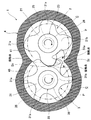
- FIG. 2 is a cross-sectional view of the first embodiment of the screw compressor of the present invention shown in FIG. 1 as viewed from the direction of arrows II-II. It is the longitudinal cross-sectional view which expanded the one part structure of 1st Embodiment of the screw compressor of this invention shown by the code
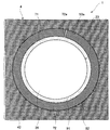
- FIG. 4 is a sectional view of a part of the configuration of the first embodiment of the screw compressor of the present invention shown in FIG. 3 as viewed from the direction of arrows IV-IV.
- FIG. 1 is a longitudinal sectional view of a screw compressor according to the first embodiment and a system diagram showing the supply of lubricating oil to the screw compressor.
- FIG. 2 shows the screw compressor shown in FIG. It is the cross-sectional view seen from vision.
- the left side is the suction side of the screw compressor, and the right side is the discharge side.
- the bold arrow represents the rotational direction of the screw compressor.
- a screw compressor 1 accommodates a male rotor (male screw rotor) 2 and a female rotor (female screw rotor) 3 that rotate in mesh with each other, and both male and female rotors 2 and 3.
- a casing 4 The male rotor 2 is rotatably supported by the suction side bearing 6 and the discharge side bearings 7 and 8, and is connected to a motor 100 as a rotational drive source.
- the female rotor 3 is rotatably supported by a suction side bearing (not shown) and a discharge side bearing (not shown).
- the male rotor 2 includes a screw-like rotor portion 21 having a plurality of spiral lobes 21a (four in FIG. 2), and both sides in the axial direction of the rotor portion 21 (the left-right direction in FIG. 1 and the vertical direction in FIG. 2). It comprises a suction-side (left side in FIG. 1) shaft portion 22 and a discharge-side (right side in FIG. 1) shaft portion 23, which are respectively arranged at the ends.
- the rotor portion 21 has a discharge-side end surface 21b facing the inner wall surface of the casing 4 with a predetermined gap (hereinafter referred to as a discharge end-surface gap) G1 on the discharge side in the axial direction.
- the suction-side shaft portion 22 extends to the outside of the casing 4 and has, for example, a configuration integrated with the shaft portion of the motor 100.
- a mechanical seal 9 is attached to the front end side of the shaft portion 22 with respect to the suction side bearing 6 in the suction side shaft portion 22.
- the discharge-side shaft portion 23 is a stepped shaft portion, and is positioned between the small-diameter shaft portion 25 to which the discharge-side bearings 7 and 8 are attached, the small-diameter shaft portion 25 and the rotor portion 21, and the small-diameter shaft portion 25. And a large-diameter shaft portion 26 having a larger diameter.
- the female rotor 3 is disposed at each of the screw-shaped rotor portion 31 having a plurality of spiral lobes 31a (six in FIG. 2) and both end portions in the axial direction (perpendicular to the plane of FIG. 2) of the rotor portion 31. And a suction side shaft portion (not shown) and a discharge side shaft portion 33.
- the rotor portion 31 has a discharge side end surface 31 b that faces the inner wall surface of the casing 4 with a discharge end surface gap on the discharge side in the axial direction.
- the discharge-side shaft portion 33 is a stepped shaft portion, like the discharge-side shaft portion 23 of the male rotor 2, and a small-diameter shaft portion 35 to which a discharge-side bearing (not shown) is attached, and a small-diameter shaft portion.
- the large-diameter shaft portion 36 is located between the rotor portion 31 and the large-diameter shaft portion 35 and is larger in diameter than the small-diameter shaft portion 35.
- the casing 4 has a main casing 41 and a discharge-side casing 42 attached to the discharge side (right side in FIG. 1) of the main casing 41.
- the main casing 41 is provided with two substantially cylindrical spaces called “bore 46” which are partially overlapped, and one side of the bore 46 in the axial direction (the right side in FIG. 1) is open.
- the bore 46 accommodates the rotor portions 21 and 31 of the male rotor 2 and the female rotor 3.
- a suction port 47 is provided in the outer peripheral portion of the main casing 41 to communicate the area of the bore 46 opposite to the opening side and the outside of the main casing 41.
- Suction side bearing chambers (the female rotor 3 side is not shown) 48 holding the suction side bearings 6 for the male rotor 2 and the female rotor 3 are respectively provided at the suction side end portions of the main casing 41 in the axial direction.
- the suction side bearing chamber 48 is open on one side (left side in FIG. 1).
- the bore 46 and the suction side bearing chamber 48 are separated by a suction side partition wall 49.
- the suction-side partition wall 49 is provided with suction-side shaft holes (not shown) 49a through which the suction-side shaft portions 22 of the male rotor 2 and the female rotor 3 are inserted.
- suction side shaft hole 49a In each suction side shaft hole 49a, the suction side shaft portion 22 of the male rotor 2 and the female rotor 3 is disposed with a predetermined gap.
- the main casing 41 is provided with a suction side cover 43 that closes the openings of both the suction side bearing chambers 48 of the male rotor 2 and the female rotor 3.
- the suction side cover 43 is provided with a cover shaft hole 43a through which the suction-side shaft portion 22 of the male rotor 2 is inserted.
- the suction side cover 43 has a seal chamber 43b in which the mechanical seal 9 is disposed on the cover shaft hole 43a side.
- the discharge side casing 42 closes the opening of the bore 46 of the main casing 41.
- the discharge side casing 42 is provided with a discharge flow path 51 that allows the outside of the discharge side casing 42 to communicate with the bore 46.
- the discharge flow path 51 has a discharge port 51 a having a predetermined shape on the end face of the discharge side casing 42 on the bore 46 side.
- a discharge-side bearing chamber (not shown on the female rotor 3 side) 52 for holding the discharge-side bearings 7 and 8 for the male rotor 2 and the female rotor 3 is provided at a portion of the discharge-side casing 42 opposite to the bore 46 side. Each is provided, and one side (the right side in FIG. 1) of the discharge side bearing chamber 52 is opened.
- the bore 46 and the discharge side bearing chamber 52 are separated by a discharge side partition wall 53.
- the discharge-side partition wall 53 is provided with a discharge-side shaft hole (not shown) 53a through which the discharge-side shaft portions 23 and 33 of the male rotor 2 and the female rotor 3 are inserted.
- the large-diameter shaft portions 26 and 36 of the discharge-side shaft portions 23 and 33 of the male rotor 2 and the female rotor 3 respectively have a predetermined gap (hereinafter referred to as a discharge-side shaft hole gap) G2 in each discharge-side shaft hole 53a.
- a discharge side cover 44 is attached to the discharge side casing 42 to close the openings of both the discharge side bearing chambers 52 of the male rotor 2 and the female rotor 3.
- the suction side cover 43 is provided with a suction side bearing oil supply passage 61 that communicates the outside of the suction side cover 43 with the seal chamber 43 b and the suction side bearing chamber 48.
- the suction-side bearing oil supply passage 61 can supply lubricating oil to the suction-side bearing 6 and the mechanical seal 9 from the outside of the screw compressor 1.
- the main casing 41 is provided with a suction-side oil recovery passage 62 that allows the suction-side bearing chamber 48 to communicate with the suction pressure region in the bore 46.
- the suction-side oil recovery path 62 guides and recovers the lubricating oil that has lubricated the suction-side bearing 6 and the mechanical seal 9 into the bore 46.
- the discharge-side casing 42 is provided with a discharge-side bearing oil supply passage 63 that allows the outside of the discharge-side casing 42 to communicate with the discharge-side shaft hole 53a.
- the discharge-side bearing oil supply path 63 enables supply of lubricating oil to the discharge-side bearings 7 and 8 from the outside of the screw compressor 1.
- the discharge-side casing 42 and the discharge-side cover 44 are provided with a discharge-side oil recovery passage 64 that allows the discharge-side bearing chamber 52 of the discharge-side casing 42 to communicate with the suction pressure region in the bore 46 of the main casing 41. .
- the discharge-side oil recovery path 64 guides and recovers the lubricating oil that lubricates the discharge-side bearings 7 and 8 into the bore 46.
- the main casing 41 is provided with a compression chamber oil supply passage 65 for communicating the outside of the main casing 41 with the bore 46.
- the compression chamber oil supply passage 65 supplies lubricating oil to the male and female rotors 2 and 3 in the bore 46.
- the suction side bearing oil supply passage 61, the discharge side bearing oil supply passage 63, and the compression chamber oil supply passage 65 are connected to the oil separator 102. Lubricating oil is supplied to these oil supply passages 61, 63 and 65 from an oil separator 102 as a lubricating oil supply source.
- a plurality of lobes 21a and 31a (rotor portions 21 and 31) of the male rotor 2 and the female rotor 3 and an inner wall surface of the casing 4 surrounding the lobes 21a and 31a are defined by the inner wall surface of the bore 46 of the main casing 41 and the end surface of the discharge-side casing 42 on the bore 46 side.
- the air as the working fluid sucked into the compression chamber C through the suction port 47 is compressed until reaching a predetermined pressure, and then discharged to the oil separator 102 through the discharge passage 51.
- the oil separator 102 the lubricating oil contained in the compressed air and the compressed air are separated.
- the compressed air from which the lubricating oil has been removed is supplied to an external compressed air consuming device (not shown), and the separated lubricating oil is stored in the oil separator 102.
- Lubricating oil stored in the oil separator 102 is cooled by an oil cooler 103 and impurities are removed by an oil filter 104, and then supplied to the screw compressor 1.
- the supply of the lubricating oil to the screw compressor 1 can be performed by the pressure of the compressed air flowing into the oil separator 102 without using a power source such as a pump.
- the lubricating oil supplied to the screw compressor 1 is supplied to the mechanical seal 9 and the suction side bearing 6 via the suction side bearing oil supply passage 61, and after lubricating the mechanical seal 9 and the suction side bearing 6, the suction side oil recovery passage is provided. It is recovered in the region of the suction process in the compression chamber C through 62.
- the discharge-side bearings 7 and 8 are also supplied with lubricating oil through the discharge-side bearing oil supply passage 63 and the discharge-side shaft hole 53a.
- the lubricating oil that has lubricated the discharge-side bearings 7 and 8 is recovered in the region of the suction process in the compression chamber C via the discharge-side oil recovery path 64.
- the lubricating oil in the oil separator 102 is supplied into the compression chamber C through the compression chamber oil supply passage 65 to cool the air in the compression process region and seal the gap between the adjacent compression chambers C. .
- the lubricating oil collected in the compression chamber C is discharged from the discharge passage 51 together with the compressed air, and flows into the oil separator 102.
- a gap of at least several tens to several hundreds ⁇ m is provided between the outer surfaces of both the male and female rotors 2 and 3 and the inner wall surface of the casing 4 in order to prevent damage due to contact.
- the discharge end surface gap G1 is provided between the discharge side end surfaces 21b and 31b of the rotor portions 21 and 31 of the male and female rotors 2 and 3 and the end surface of the discharge side casing 42 on the bore 46 side.
- a discharge-side shaft hole gap G2 is provided between the large-diameter shaft portions 26, 36 of the discharge-side shaft portions 23, 33 of the male and female rotors 2, 3 and the discharge-side shaft hole 53a of the discharge-side casing 42. It has been.
- the screw compressor 1 further includes a discharge-side shaft sealing portion that seals that the working fluid leaks from the discharge-side shaft hole gap G2.
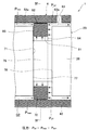
- FIG. 3 is an enlarged longitudinal sectional view of a part of the discharge side shaft seal portion of the screw compressor indicated by the symbol X in FIG. 1
- FIG. 4 is a view of a part of the discharge side shaft seal portion of the screw compressor shown in FIG. It is sectional drawing seen from the IV-IV arrow.
- the left side is the suction side of the screw compressor
- the right side is the discharge side. 3 and 4, the same reference numerals as those shown in FIG. 1 and FIG. 2 are the same parts, and detailed description thereof will be omitted.
- the discharge-side shaft sealing portion includes an annular groove portion 71 provided on an outer peripheral portion facing the inner wall surface of the discharge-side shaft hole 53a in the large-diameter shaft portion 26 of the discharge-side shaft portion 23, and an annular shape.
- a seal ring 72 disposed in the groove 71 is provided in the discharge-side casing 42 so as to communicate the outside of the discharge-side casing 42 and the discharge-side shaft hole 53a.
- 1 and 3 is provided with a shaft-sealed fluid supply path capable of supplying fluid to the left or right side.
- the discharge-side bearing oil supply passage 63 is used as the shaft seal fluid supply passage.
- the discharge-side bearing oil supply passage 63 has a function of supplying the lubricant to the discharge-side bearings 7 and 8 from the outside of the screw compressor 1, and also supplies the lubricant (fluid) to the seal ring 72 from the outside of the screw compressor 1. It also has a function of supplying
- the annular groove 71 includes a bottom surface 76 extending in the circumferential direction of the large-diameter shaft portion 26 of the discharge-side shaft portion 23, and a shaft portion proximal end side rising in the radial direction from the bottom surface 76 (FIG. 3).
- the annular groove 71 is, for example, an annular shape having a rectangular cross-sectional shape.
- the seal ring 72 has an annular shape, and has, for example, a joint 72 a divided at one place in the circumferential direction. By expanding the joint 72 a, the seal ring 72 is formed in the annular groove 71. It is configured so that it can be easily mounted.
- the seal ring 72 is formed of, for example, a resin material, expands due to the heat of the lubricating oil (fluid) supplied through the discharge-side bearing oil supply passage 63, and the mating port 72a comes into contact with the gap in the circumferential direction. It is configured so as not to have an annular shape.
- the seal ring 72 is set so that its axial width is smaller than the groove width of the annular groove portion 71, and is configured to be movable in the axial direction of the discharge-side shaft portion 23 in the annular groove portion 71. ing.
- the seal ring 72 receives the pressure of the lubricating oil (fluid) on either one side or the inner periphery of the seal ring 72, so that the other side in the axial direction slides on either side wall surface 77 or 78 of the annular groove 71.
- the outer peripheral portion is in sliding contact with the inner wall surface of the discharge side shaft hole 53a to seal the discharge side shaft hole gap G2.
- the seal ring 72 is formed so that its cross-sectional shape is rectangular, and its outer surface is an inner peripheral surface 91, an outer peripheral surface 92, and the proximal end side of the shaft portion 23 on the discharge side in the axial direction (in FIG. 3).
- the opening 63a on the discharge-side shaft hole 53a side is located on the distal end side (right side in FIG. 3) of the shaft portion 23 on the discharge side with respect to the seal ring 72.
- the fluid is supplied to the distal end side (second side surface 94 side) of the shaft portion 23 in the axial direction of the seal ring 72.
- lubricating oil supplied to the discharge-side bearings 7 and 8 is used as the fluid supplied to the shaft seal fluid supply path.
- Lubricating oil (fluid) is supplied from the oil separator 102 to the discharge-side bearing oil supply passage 63.
- the oil separator 102 functions as a lubricant supply source for the discharge-side bearings 7 and 8 and also functions as a shaft seal fluid supply source for the seal ring 72.
- the pressure of the lubricating oil (fluid) supplied to the second side surface 94 side of the seal ring 72 through the discharge side bearing oil supply passage 63 is the base end side (first side of the shaft portion 23 in the seal ring 72 in the axial direction. It is set to be higher than the pressure acting on the side surface 93 side, that is, the pressure of air (working fluid) flowing into the discharge-side shaft hole gap G2.
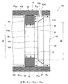
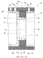
- FIG. 5 is an explanatory view showing a shaft seal portion of a conventional screw compressor as a comparative example of the first embodiment.
- the same reference numerals as those shown in FIGS. 1 to 4 are the same parts, and detailed description thereof is omitted.
- the plurality of compression chambers C contract while moving in the axial direction along with the rotation of the male rotor 2 and the female rotor 3, so that the air in the compression chamber C (working fluid) ).
- the pressure of the compressed air (working fluid) in the vicinity of the discharge side end faces 21b and 31b of the rotor portions 21 and 31 of the male rotor 2 and the female rotor 3 is the rotational direction (circumferential direction) of each compression chamber C. )
- pressure distribution exists in the circumferential direction in the compressed air near the discharge side end faces 21b and 31b of the rotor portions 21 and 31.
- the region (2) becomes a higher pressure region in the direction of the arrow P of the two-dot chain line.
- the male rotor 2 and the female rotor 3 contact at three theoretical points, the upper high pressure discharge space Ds and the lower side The low pressure suction space Ss is mixed.
- the meshing state (contact state) of the male rotor 2 and the female rotor 3 in the vicinity of the discharge side end faces 21b and 31b changes according to the rotational positions of the male rotor 2 and the female rotor 3, the male rotor 2 and the female rotor 3
- the pressure distribution in the meshing region also differs from the above case depending on the rotational positions of the male rotor 2 and the female rotor 3.
- an annular groove portion 111 is provided in the discharge-side shaft portion 23, and a seal ring 112 is disposed in the annular groove portion 111.
- the pressure of the compressed air leaking from the compression chamber C to the discharge side shaft hole gap G2 is applied to the inner peripheral surface 121 of the seal ring 112 and the first side surface 123 on the rotor portion 21 side (in FIG. 5).
- the outer peripheral surface 122 of the seal ring 112 is pressed against the discharge side shaft hole 53a, and the second side surface 124 (the right side surface in FIG. 5) of the seal ring 112 on the discharge side bearing chamber 52 side.
- the discharge side shaft hole gap G2 is sealed by pressing against the side wall surface 118 (the right side wall surface in FIG. 5) of the annular groove 111 on both side wall surfaces 117, 118 on the discharge side bearing chamber 52 side.
- the pressure of the compressed air acting on the first side surface 123 of the seal ring 112 is not uniform in the circumferential direction, A distribution occurs from the minimum pressure (P min ) to the maximum pressure (P max ).
- the maximum pressure (P max ) acts on the lower region of the first side surface 123 of the seal ring 112, and the minimum pressure (P min ) acts on the upper region on the opposite side.
- substantially the same pressure (P b ) as the discharge-side bearing chamber 52 acts uniformly on the second side surface 124 of the seal ring 112 in the circumferential direction.
- the minimum pressure (P min ) of the compressed air that leaks may be lower than the pressure (P b ) in the discharge-side bearing chamber 52 depending on the operating conditions of the screw compressor 110.
- the lubricating oil having a pressure (P oil ) larger than the maximum pressure (P max ) of the compressed air leaking into the discharge side shaft hole gap G2 is discharged. It is supplied to the discharge side shaft hole 53a (discharge side shaft hole gap G2) through the side bearing oil supply passage (shaft seal fluid supply passage) 63.
- the circumferential pressure region of the inner peripheral surface 91 of the seal ring 72 and the second side surface 94 (the right side surface in FIG. 3) near the discharge-side bearing oil supply passage 63 is relatively high in pressure (P oil ). Therefore, the seal ring 72 receives a force in the proximal direction (left direction in FIG.
- the seal ring 72 since the pressure (P oil ) higher than the maximum pressure (P max ) of the compressed air always acts on the entire circumferential direction of the second side surface 94 of the seal ring 72, the seal ring 72 is within the annular groove 71. Tilt can be prevented. Therefore, the first side surface 93 of the seal ring 72 and the first side wall surface 77 of the annular groove 71 and the outer peripheral surface 92 of the seal ring 72 and the discharge-side shaft hole 53a are surely brought into sliding contact. Further, the seal ring 72 has no gap between the mating holes 72a due to thermal expansion. Therefore, the leakage of the compressed air in the discharge side shaft hole gap G2 is blocked. For this reason, the compressed air which leaks from the compression chamber C to the discharge side bearing chamber 52 (refer FIG. 1) reduces remarkably, and the energy saving of the screw compressor 1 is attained.
- the lubricating oil supplied to the discharge-side shaft hole gap G2 via the discharge-side bearing oil supply passage 63 applies pressure to the second side surface 94 of the seal ring 72, and then lubricates the discharge-side bearings 7 and 8. . Thereafter, the lubricating oil flows into the compression chamber C in the suction process via the discharge-side oil recovery passage 64 and is discharged to the outside together with the compressed air from the discharge passage 51.
- the shaft seal fluid supply path also functions as the discharge side bearing oil supply path 63 for supplying the lubricant to the discharge side bearings 7 and 8
- the shaft seal fluid supply path and the discharge side The structure can be simplified compared to the configuration in which the bearing oil supply passage 63 is provided individually.
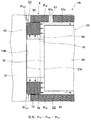
- FIG. 6 is an enlarged longitudinal sectional view of a part of the discharge-side shaft seal portion of the screw compressor according to the first modification of the first embodiment.
- the left side is the suction side of the screw compressor
- the right side is the discharge side.
- the same reference numerals as those shown in FIGS. 1 to 5 are the same parts, and detailed description thereof will be omitted.
- the screw compressor 1A according to the first modification of the first embodiment shown in FIG. 6 has a configuration substantially similar to that of the first embodiment, but the shape and shaft of the annular groove 71A of the discharge side shaft sealing portion The position of the opening 63b on the discharge side shaft hole 53a side of the discharge side bearing oil supply path 63A as the sealed fluid supply path is different.
- the second side wall surface 78A near the discharge-side bearing oil supply passage 63A of the annular groove 71A has a groove opening side portion closer to the discharge-side bearing oil supply passage 63A than a portion on the bottom surface 76 side.
- the second side wall surface 78A includes a bottom surface-side vertical surface 80 that rises in the radial direction from the bottom surface 76, and a groove opening-side inclined surface 81 that is inclined toward the discharge-side bearing oil supply passage 63A with respect to the vertical surface 80. It consists of The inclined surface 81 forms a fluid reservoir Fs that can store lubricating oil (fluid) together with the inner wall surface of the discharge-side shaft hole 53a.
- the outermost diameter of the vertical surface 80 or the innermost diameter (do) of the inclined surface 81 is set to be larger than the inner diameter (ds) of the seal ring 72.
- the inclined surface 81 can be easily formed by chamfering the groove opening portion of the second side wall surface 78 of the annular groove portion 71 of the screw compressor 1 according to the first embodiment.
- the discharge-side bearing oil supply passage 63A is set such that the axial position of the opening 63b is the arrangement position of the inclined surface 81 of the annular groove 71A. That is, the discharge-side bearing oil supply passage 63A opens and communicates with the fluid storage portion Fs.
- the lubricating oil is screwed by the pressure of the compressed air (working fluid) discharged from the screw compressor 1 to the oil separator 102. Supplied to the compressor 1.
- the screw compressor 1 when the screw compressor 1 is started, first, the air (working fluid) sucked into the compression chamber C is compressed and its pressure rises. Thereafter, the compressed air discharged from the screw compressor 1 flows into the oil separator 102, and the pressure in the oil separator 102 increases.
- the maximum pressure (P max ) of the air in the discharge side shaft hole gap G2 is greater than the pressure (P oil ) of the lubricating oil supplied to the discharge side shaft hole gap G2. Increases in a short time. That is, at the time of starting, the maximum pressure (P max ) of the compressed air in the discharge-side shaft hole gap G2 is temporarily higher than the pressure (P oil ) of the lubricating oil.
- the pressure of the compressed air in the discharge-side shaft hole gap G ⁇ b> 2 moves the seal ring 72 toward the discharge-side bearing oil supply path 63 in the annular groove 71, and the second side surface 94 is the second groove 94. There is a possibility of being pressed against the side wall surface 78. In this case, even if the pressure (P oil ) of the lubricating oil in the discharge-side shaft hole gap G2 subsequently becomes larger than the maximum pressure (P max ) of the compressed air, the seal ring 72 is on the first side wall surface 77 side of the annular groove 71. There is a concern that will not be pushed back.
- the size of the discharge side shaft hole gap G2 is several tens to several hundreds ⁇ m, which is significantly smaller than the width (eg, several mm) of the side surfaces 93 and 94 of the seal ring 72. This is because the pressure receiving area on the axial side surface on the 63rd side is small. Even in this situation, the discharge-side shaft hole gap G2 can be sealed.
- the side surfaces 93 and 94 of the seal ring 72 that are in sliding contact with the annular groove 71 vary depending on operating conditions, there arises a problem that it is difficult to predict the life due to wear of the seal ring 72.
- the seal ring 72 When the screw compressor 1 is installed vertically so that the suction side is on the upper side and the discharge side is on the lower side, the seal ring 72 has the second weight of the annular groove 71 by its own weight when the screw compressor 1 is started. It will be in the state which contacted the side wall surface 78. Therefore, also in this case, there is a problem described above.
- the innermost diameter (do) of the inclined surface 81 of the second side wall surface 78A of the annular groove 71A is set to be larger than the inner diameter (ds) of the seal ring 72.
- the groove opening side portion (inclined surface 81) of the second side wall surface 78A on the side close to the discharge-side bearing oil supply passage 63A of the annular groove portion 71A is disposed on the bottom side of the second side wall surface 78A. Since the portion (vertical surface 80) is positioned on the discharge side bearing oil supply passage 63A side and the fluid storage portion Fs is formed by the inclined surface 81 and the discharge side shaft hole 53a, the seal ring 72 is provided on the discharge side bearing oil supply.
- the pressure receiving area of the second side surface 94 of the seal ring 72 becomes larger than the cross-sectional area of the discharge-side shaft hole gap G2. Accordingly, the seal ring 72 can be slid back into contact with the first side wall surface 77 of the annular groove 71A. As a result, since the first side surface 93 of the seal ring 72 is always worn, it is easy to predict the life of the seal ring 72.
- the discharge-side bearing oil supply passage 63A as the shaft-sealed fluid supply passage is configured to open to the fluid storage portion Fs, so that the seal is provided without passing through the narrow space of the discharge-side shaft hole gap G2.
- the fluid can be supplied to the second side surface 94 of the ring 72, and the pressure loss of the fluid supplied to the seal ring 72 can be reduced.
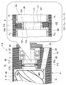
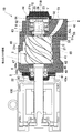
- FIG. 7 is a longitudinal sectional view of a screw compressor according to a second modification of the first embodiment
- FIG. 8 is a longitudinal section in which a part of the discharge-side shaft seal portion of the screw compressor indicated by symbol Y in FIG. 7 is enlarged.
- FIG. 7 and 8 the left side is the suction side of the screw compressor, and the right side is the discharge side. 7 and 8, since the same reference numerals as those shown in FIGS. 1 to 6 are the same parts, detailed description thereof is omitted.
- the screw compressor 1B according to the second modification of the first embodiment shown in FIGS. 7 and 8 has a configuration substantially similar to that of the first embodiment, except that the annular groove 71B of the discharge side shaft seal portion is Installation position is different. Specifically, the annular groove 71B is provided at the most proximal end portion of the large-diameter shaft portion 26 of the shaft portion 23, and the first side wall surface on the rotor portion 21 side is the discharge-side end surface of the rotor portion 21. 21b.
- the pressure of compressed air (working fluid) in the discharge-side shaft hole gap G 2 acts on the first side surface 93 of the seal ring 72.
- the pressure of the compressed air leaking into the discharge end face gap G1 acts on the outer peripheral surface 92 of the seal ring 72.
- the inner peripheral surface 91 and the second side surface 94 of the seal ring 72 have a lubricating oil having a pressure higher than the maximum pressure (P max ) of the compressed air ( The fluid pressure (P oil ) acts uniformly in the circumferential direction.
- the outer peripheral surface 92 and the first side surface 93 of the seal ring 72 are pressed against the discharge side shaft hole 53a and the discharge side end surface 21b of the rotor portion 21 against the pressure of the compressed air leaked into the discharge end surface gap G1, respectively. It is done. As a result, the first side surface 93 of the seal ring 72 and the discharge side end surface 21b of the rotor portion 21 and the outer peripheral surface 92 of the seal ring 72 and the discharge side shaft hole 53a are in sliding contact with each other. Leakage from the discharge side shaft hole gap G2 is blocked.
- the region of the first side surface 93 of the seal ring 72 excluding the outer peripheral end portion is in sliding contact with the first side wall surface 77 of the annular groove 71.
- the entire surface of the first side surface 93 of the seal ring 72 is in sliding contact with the discharge-side end surface 21b of the rotor portion 21. Therefore, uneven wear of the seal ring 72 is prevented, and the life of the seal ring 72 can be increased.
- the discharge-side end surface 21b of the rotor portion 21 constitutes the side wall surface of the annular groove portion 71 that is in sliding contact with the seal ring 72, so that uneven wear of the seal ring 72 is prevented and the length of the seal ring 72 is increased. Life can be extended.
- the discharge-side end surface 21 b of the rotor portion 21 constitutes the side wall surface of the annular groove portion 71 that is in sliding contact with the seal ring 72. Reduces the amount of contact. Therefore, leakage of compressed air between the compression chambers C via the discharge end face gap G1 can be suppressed.
- the seal ring 72 is brought into sliding contact with the discharge-side end surface 21b of the rotor portion 21, so that the pressure of the compressed air (working fluid) in the discharge end surface gap G1 on the outer peripheral surface 92 of the seal ring 72 is reached.
- pressure (P oil ) of lubricating oil (fluid) having a pressure higher than the maximum pressure (P max ) of compressed air in the discharge end face gap G1 acts on the inner peripheral surface 91.
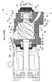
- FIG. 9 is a longitudinal sectional view of a screw compressor according to the second embodiment
- FIG. 10 is an enlarged longitudinal sectional view of a part of a discharge side shaft seal portion of the screw compressor indicated by reference numeral Z in FIG. 9 and 10, the left side is the suction side of the screw compressor, and the right side is the discharge side.
- the same reference numerals as those shown in FIGS. 1 to 8 are the same parts, and detailed description thereof will be omitted.
- the screw compressor 1C according to the second embodiment shown in FIGS. 9 and 10 is different from the first embodiment in that a shaft seal fluid supply path 73 is newly provided separately from the discharge side bearing oil supply path 63. In addition, a shaft seal fluid recovery path 74 for recovering the fluid supplied to the seal ring 72 is newly provided.
- the shaft seal fluid supply path 73 is provided in the discharge side casing 42 so as to communicate the outside of the discharge side casing 42 and the discharge side shaft hole 53a.
- the opening 73a on the discharge side shaft hole 53a side of the shaft seal fluid supply path 73 is provided so as to be located on the proximal end side (left side in FIGS. 9 and 10) of the shaft portion 23 on the discharge side with respect to the seal ring 72. ing.
- the shaft seal fluid supply path 73 supplies fluid to the base end side (first side surface 93 side) of the shaft portion 23 in the axial direction of the seal ring 72.
- the pressure (P oil2 ) of the fluid supplied to the first side surface 93 side of the seal ring 72 via the shaft seal fluid supply path 73 is the tip side (second side surface ) of the shaft portion 23 in the axial direction in the seal ring 72. 94 side), that is, higher than the pressure (P oil1 ) of the lubricating oil for the discharge-side bearings 7 and 8 supplied to the discharge-side shaft hole gap G2 via the discharge-side bearing oil supply passage 63.
- Lubricating oil as a fluid is supplied to the shaft seal fluid supply path 73 from, for example, an oil separator 102 as a shaft seal fluid supply source.
- an oil separator 102 as a shaft seal fluid supply source.
- the lubricating oil supplied via the shaft seal fluid supply passage 73 and A pressure difference from the lubricating oil supplied through the discharge-side bearing oil supply passage 63 is ensured.
- the shaft seal fluid recovery passage 74 is provided in the discharge side casing 42 so as to communicate with the discharge side shaft hole 53a.
- the opening 74a on the discharge-side shaft hole 53a side of the shaft seal fluid recovery passage 74 is located on the base end side (left side in FIGS. 9 and 10) of the shaft portion 23 relative to the opening 73a of the shaft seal fluid supply passage 73. It is provided as follows.
- the lubricating oil pressure of the lubricating oil supplied through the discharge-side bearing oil supply passage 63 (P oil1) pressure greater than (P OIL2), the discharge side via the shaft seal fluid supply channel 73 Supply to the shaft hole gap G2.
- P oil1 pressure greater than (P OIL2) the lubricating oil pressure of the lubricating oil supplied through the discharge-side bearing oil supply passage 63
- P OIL2 the lubricating oil pressure of the lubricating oil supplied through the discharge-side bearing oil supply passage 63
- P oil1 pressure greater than (P OIL2) the discharge side via the shaft seal fluid supply channel 73 Supply to the shaft hole gap G2.
- the second side surface 94 (the right side surface in FIGS. 9 and 10) is pressed against the second side wall surface 78 of the annular groove 71, and the outer peripheral surface 92 is pressed against the inner wall surface of the discharge side shaft hole 53a.
- the gap of the abutment 72a disappears due to thermal expansion. Accordingly, since the leakage of the working fluid (compressed air) in the discharge side shaft hole gap G2 is blocked, the compressed air leaking from the compression chamber C to the discharge side bearing chamber 52 is remarkably reduced, and energy saving of the screw compressor 1C is achieved. Is possible.
- the lubricating oil supplied to the discharge-side shaft hole gap G2 through the shaft seal fluid supply passage 73 applies pressure to the first side surface 93 of the seal ring 72 on the shaft seal fluid supply passage 73 side, and then the shaft seal fluid. It is sucked into the collection path 74. Thereafter, the lubricating oil in the shaft seal fluid recovery passage 74 flows into the compression chamber C in the suction process via the discharge side oil recovery passage 64 and is discharged to the outside together with the compressed air from the discharge passage 51.
- the second side surface 94 (shaft) is provided on the first side surface 93 side (one axial side) of the seal ring 72 via the shaft seal fluid supply passage 73. Since the lubricating oil (fluid) having a pressure (P oil2 ) higher than the pressure (P oil1 ) of the lubricating oil for the discharge side bearings 7 and 8 acting on the other side in the direction) is supplied, it leaks into the discharge side shaft hole gap G2. Even if there is a circumferential pressure distribution in the compressed air (working fluid), the seal ring 72 is uniformly pressed against the inner wall surface of the discharge-side shaft hole 53a and the second side wall surface 78 of the annular groove portion 71 and tilted. There is no. Therefore, the discharge side shaft hole gap G2 can be reliably sealed, and high shaft sealing performance can be exhibited.
- the opening 73 a of the shaft seal fluid supply path 73 is provided on the proximal end side of the shaft portion 23 on the discharge side with respect to the seal ring 72, and thus the first side surface 93 of the seal ring 72.
- the pressure of the relatively high pressure lubricating oil (fluid) supplied through the shaft seal fluid supply passage 73 and the pressure of air (working fluid) leaking to the discharge side shaft hole gap G2 on the side (rotor portion 21 side) Receive.
- the second side surface 94 of the seal ring 72 is always in sliding contact with the annular groove 71. That is, since the side surface 94 of the seal ring 72 that is in sliding contact with the annular groove 71 does not change depending on the operating conditions of the screw compressor 1C, it is easy to predict the life due to wear of the seal ring 72.
- the relatively high-pressure lubricating oil (fluid) supplied to the discharge-side shaft hole gap G2 via the shaft seal fluid supply passage 73 is recovered by the shaft seal fluid recovery passage 74. It is possible to prevent the lubricating oil (fluid) from leaking from the discharge side shaft hole gap G2 to the discharge end face gap G1. For this reason, the stirring power resulting from the lubricating oil (fluid) leaking into the discharge end face gap G1 can be reduced.
- the present invention is not limited to the above-described embodiments, and includes various modifications.
- the above-described embodiment has been described in detail for easy understanding of the present invention, and is not necessarily limited to the one having all the configurations described. That is, part of the configuration of a certain embodiment can be replaced with the configuration of another embodiment, and the configuration of another embodiment can be added to the configuration of a certain embodiment. Moreover, it is also possible to add, delete, or replace another configuration for a part of the configuration of each embodiment.
- the screw compressors 1, 1A, 1B, and 1C that compress air are described as examples.
- the present invention is applied to a screw compressor that compresses a refrigerant such as ammonia or CO2. Can do.
- the oil supply type screw compressors 1, 1 ⁇ / b> A, 1 ⁇ / b> B, and 1 ⁇ / b> C have been described as examples, the present invention can be applied to a water lubricated screw compressor to which water is supplied.
- twin rotor type screw compressors 1, 1A, 1B, and 1C have been described as examples, the present invention can also be applied to screw compressors other than twin rotor types such as a single rotor type and a triple rotor type.
- the rotor portion of the screw rotor has a plurality of spiral grooves that mesh with the teeth of the gate rotor, and has a screw shape.
- the cross-sectional shape of the seal ring 72 is rectangular.
- either the outer peripheral portion or the axial direction of the seal ring is the discharge side shaft hole 53a and the annular groove portions 71 and 71A.
- Any shape can be used as long as it is in sliding contact with the side wall surface and seals the discharge-side shaft hole gap G2.
- the second side wall surface 78A on the side close to the discharge-side bearing oil supply passage 63A of the annular groove 71A is replaced with the vertical surface 80 on the bottom surface side and the groove opening.
- the example comprised with the side inclined surface 81 was shown.
- the portion of the second side wall surface 78A on the groove opening side is located on the discharge side bearing oil supply passage (shaft seal fluid supply passage) 63A side with respect to the vertical surface 80, and is fluid together with the inner wall surface of the discharge side shaft hole 53a.
- the storage part formation surface which forms the storage part Fs is not an inclined surface but a staircase-shaped storage portion forming surface 81D.
Landscapes
- Engineering & Computer Science (AREA)
- General Engineering & Computer Science (AREA)
- Mechanical Engineering (AREA)
- Physics & Mathematics (AREA)
- Architecture (AREA)
- Fluid Mechanics (AREA)
- Applications Or Details Of Rotary Compressors (AREA)
- Sealing Devices (AREA)
Abstract
La présente invention concerne un compresseur à vis équipé : d'un rotor à vis (2) qui est formé à partir d'une partie rotor (21) et d'une partie arbre (23); d'un boîtier (4) qui est pourvu d'un trou d'arbre (53a) à travers lequel la partie arbre (23) est insérée, et qui loge le rotor à vis (2); et d'une partie d'étanchéité d'arbre côté évacuation qui scelle la fuite d'un fluide de travail à partir d'un espace G2 entre la partie arbre (23) et le trou d'arbre (53a). La partie d'étanchéité d'arbre côté évacuation est pourvue : d'une rainure annulaire (71 qui est disposée sur la partie d'arbre (23); d'une bague d'étanchéité (72) qui est disposée à l'intérieur de la rainure annulaire (71) de manière à pouvoir se déplacer dans la direction axiale de la partie arbre (23), et qui est apte à entrer en contact coulissant avec le trou d'arbre (53a) et les surfaces de paroi latérale (77, 78) de la rainure annulaire (71); et d'un canal d'alimentation en fluide d'étanchéité d'arbre qui communique avec le trou d'arbre (53a) et est destiné à fournir un fluide de chaque côté de la bague d'étanchéité (72) dans la direction axiale. La pression du fluide fourni par l'intermédiaire du canal d'alimentation en fluide d'étanchéité d'arbre à un côté de la bague d'étanchéité (72) dans la direction axiale est réglée plus haut que la pression agissant sur l'autre côté dans la direction axiale. Par conséquent, une excellente performance d'étanchéité d'arbre peut être obtenue même s'il y a une répartition de pression dans la direction circonférentielle dans le fluide de travail sur le côté d'évacuation du rotor à vis (2).
Priority Applications (2)
| Application Number | Priority Date | Filing Date | Title |
|---|---|---|---|
| CN201880087626.7A CN111670306B (zh) | 2016-12-22 | 2018-02-21 | 螺旋式压缩机 |
| US16/971,575 US11428228B2 (en) | 2016-12-22 | 2018-02-21 | Screw compressor having a different pressure of the fluid applied to the seal ring on the delivery side shaft sealing unit |
Applications Claiming Priority (2)
| Application Number | Priority Date | Filing Date | Title |
|---|---|---|---|
| JP2016-249553 | 2016-12-22 | ||
| JP2016249553A JP6707021B2 (ja) | 2016-12-22 | 2016-12-22 | スクリュー圧縮機 |
Publications (2)
| Publication Number | Publication Date |
|---|---|
| WO2018117276A1 true WO2018117276A1 (fr) | 2018-06-28 |
| WO2018117276A8 WO2018117276A8 (fr) | 2018-08-23 |
Family
ID=62626901
Family Applications (1)
| Application Number | Title | Priority Date | Filing Date |
|---|---|---|---|
| PCT/JP2018/006146 WO2018117276A1 (fr) | 2016-12-22 | 2018-02-21 | Compresseur à vis |
Country Status (4)
| Country | Link |
|---|---|
| US (1) | US11428228B2 (fr) |
| JP (1) | JP6707021B2 (fr) |
| CN (1) | CN111670306B (fr) |
| WO (1) | WO2018117276A1 (fr) |
Cited By (2)
| Publication number | Priority date | Publication date | Assignee | Title |
|---|---|---|---|---|
| US20170276137A1 (en) * | 2014-09-19 | 2017-09-28 | Gree Electric Appliances, Inc. Of Zhuhai | Exhaust bearing seat, screw compressor and air-conditioning unit |
| CN115614109A (zh) * | 2022-10-13 | 2023-01-17 | 中国航发四川燃气涡轮研究院 | 一种耐负压圆周石墨密封结构 |
Citations (3)
| Publication number | Priority date | Publication date | Assignee | Title |
|---|---|---|---|---|
| JPH01163492A (ja) * | 1987-12-18 | 1989-06-27 | Hitachi Ltd | スクリユー真空ポンプ |
| JP2005214045A (ja) * | 2004-01-28 | 2005-08-11 | Mayekawa Mfg Co Ltd | スクリュー圧縮装置 |
| JP2012127314A (ja) * | 2010-12-17 | 2012-07-05 | Kobe Steel Ltd | 水噴射式スクリュ流体機械 |
Family Cites Families (13)
| Publication number | Priority date | Publication date | Assignee | Title |
|---|---|---|---|---|
| US3971563A (en) * | 1973-09-17 | 1976-07-27 | Mitsui Shipbuilding And Engineering Co., Ltd. | Shaft sealing apparatus using a fluid sealing system |
| JPS5951190A (ja) * | 1982-09-17 | 1984-03-24 | Hitachi Ltd | オイルフリ−スクリユ−圧縮機の油切り装置 |
| US5281116A (en) * | 1993-01-29 | 1994-01-25 | Eaton Corporation | Supercharger vent |
| SE500488C2 (sv) * | 1993-05-14 | 1994-07-04 | Svenska Rotor Maskiner Ab | Skruvkompressor med tätningsorgan |
| BE1010915A3 (nl) * | 1997-02-12 | 1999-03-02 | Atlas Copco Airpower Nv | Inrichting voor het afdichten van een rotoras en schroefcompressor voorzien van dergelijke inrichting. |
| DE10040020A1 (de) | 2000-08-16 | 2002-03-07 | Bitzer Kuehlmaschinenbau Gmbh | Schraubenverdichter |
| JP4431184B2 (ja) * | 2008-06-13 | 2010-03-10 | 株式会社神戸製鋼所 | スクリュ圧縮装置 |
| EP2910823A4 (fr) * | 2012-10-19 | 2016-05-18 | Eagleburgmann Japan Co Ltd | Joint à soufflets |
| JP6088212B2 (ja) * | 2012-11-07 | 2017-03-01 | 株式会社日立産機システム | スクリュー圧縮機 |
| JP5904961B2 (ja) * | 2013-03-14 | 2016-04-20 | 株式会社日立産機システム | スクリュー圧縮機 |
| JP6469549B2 (ja) * | 2014-09-29 | 2019-02-13 | 株式会社神戸製鋼所 | オイルフリースクリュ圧縮機 |
| JP6284466B2 (ja) * | 2014-09-29 | 2018-02-28 | 株式会社神戸製鋼所 | オイルフリースクリュ圧縮機 |
| JP2017044123A (ja) * | 2015-08-26 | 2017-03-02 | ジョンソンコントロールズ ヒタチ エア コンディショニング テクノロジー(ホンコン)リミテッド | スクリュー圧縮機 |
-
2016
- 2016-12-22 JP JP2016249553A patent/JP6707021B2/ja active Active
-
2018
- 2018-02-21 WO PCT/JP2018/006146 patent/WO2018117276A1/fr active Application Filing
- 2018-02-21 CN CN201880087626.7A patent/CN111670306B/zh active Active
- 2018-02-21 US US16/971,575 patent/US11428228B2/en active Active
Patent Citations (3)
| Publication number | Priority date | Publication date | Assignee | Title |
|---|---|---|---|---|
| JPH01163492A (ja) * | 1987-12-18 | 1989-06-27 | Hitachi Ltd | スクリユー真空ポンプ |
| JP2005214045A (ja) * | 2004-01-28 | 2005-08-11 | Mayekawa Mfg Co Ltd | スクリュー圧縮装置 |
| JP2012127314A (ja) * | 2010-12-17 | 2012-07-05 | Kobe Steel Ltd | 水噴射式スクリュ流体機械 |
Cited By (4)
| Publication number | Priority date | Publication date | Assignee | Title |
|---|---|---|---|---|
| US20170276137A1 (en) * | 2014-09-19 | 2017-09-28 | Gree Electric Appliances, Inc. Of Zhuhai | Exhaust bearing seat, screw compressor and air-conditioning unit |
| US10302086B2 (en) * | 2014-09-19 | 2019-05-28 | Gree Electric Appliances, Inc. Of Zhuhai | Exhaust bearing seat, screw compressor and air-conditioning unit |
| CN115614109A (zh) * | 2022-10-13 | 2023-01-17 | 中国航发四川燃气涡轮研究院 | 一种耐负压圆周石墨密封结构 |
| CN115614109B (zh) * | 2022-10-13 | 2024-05-17 | 中国航发四川燃气涡轮研究院 | 一种耐负压圆周石墨密封结构 |
Also Published As
| Publication number | Publication date |
|---|---|
| CN111670306A (zh) | 2020-09-15 |
| CN111670306B (zh) | 2022-04-15 |
| JP2018105144A (ja) | 2018-07-05 |
| US11428228B2 (en) | 2022-08-30 |
| JP6707021B2 (ja) | 2020-06-10 |
| WO2018117276A8 (fr) | 2018-08-23 |
| US20200378385A1 (en) | 2020-12-03 |
Similar Documents
| Publication | Publication Date | Title |
|---|---|---|
| US9068571B2 (en) | Seal for oil-free rotary displacement compressor | |
| US20100253005A1 (en) | Seal for oil-free rotary displacement compressor | |
| JP5017052B2 (ja) | スクリュ流体機械 | |
| JP5904961B2 (ja) | スクリュー圧縮機 | |
| JP2561093B2 (ja) | ベ−ン型コンプレツサ | |
| JP2008050963A (ja) | 気体圧縮機 | |
| WO2018117276A1 (fr) | Compresseur à vis | |
| JPH0140237B2 (fr) | ||
| JP5178612B2 (ja) | スクリュー圧縮機 | |
| JP2008121479A (ja) | 密閉形スクリュー圧縮機 | |
| US20100260637A1 (en) | Single-screw compressor | |
| WO2015114851A1 (fr) | Compresseur à vis | |
| KR20050103954A (ko) | 로터리 피스톤 펌프 | |
| US20200003211A1 (en) | Screw compressor | |
| EP0967392A1 (fr) | Compresseur à spirales avec joint étanche axial à l'huile entre spirale et plaque d'extrémité | |
| JP2014074350A (ja) | スクリュ圧縮機および圧縮装置 | |
| JP6130271B2 (ja) | スクロール圧縮機 | |
| KR100556796B1 (ko) | 고압식 스크롤 압축기의 배압 실링 장치 | |
| JP2018105144A5 (fr) | ||
| WO2020053976A1 (fr) | Compresseur à vis | |
| JP6461504B2 (ja) | スクロール圧縮機 | |
| JP2009041576A (ja) | スクロール型コンプレッサ | |
| US20240392785A1 (en) | Screw Compressor | |
| JP2010242656A (ja) | シングルスクリュー圧縮機 | |
| JP4106223B2 (ja) | 気体圧縮機 |
Legal Events
| Date | Code | Title | Description |
|---|---|---|---|
| 121 | Ep: the epo has been informed by wipo that ep was designated in this application |
Ref document number: 18732230 Country of ref document: EP Kind code of ref document: A1 |
|
| NENP | Non-entry into the national phase |
Ref country code: DE |
|
| 122 | Ep: pct application non-entry in european phase |
Ref document number: 18732230 Country of ref document: EP Kind code of ref document: A1 |