WO2018116801A1 - 電子制御装置、制御システム、リセット判定方法 - Google Patents
電子制御装置、制御システム、リセット判定方法 Download PDFInfo
- Publication number
- WO2018116801A1 WO2018116801A1 PCT/JP2017/043490 JP2017043490W WO2018116801A1 WO 2018116801 A1 WO2018116801 A1 WO 2018116801A1 JP 2017043490 W JP2017043490 W JP 2017043490W WO 2018116801 A1 WO2018116801 A1 WO 2018116801A1
- Authority
- WO
- WIPO (PCT)
- Prior art keywords
- electronic control
- control device
- reset
- controller
- communication
- Prior art date
- Legal status (The legal status is an assumption and is not a legal conclusion. Google has not performed a legal analysis and makes no representation as to the accuracy of the status listed.)
- Ceased
Links
Images





Classifications
-
- G—PHYSICS
- G05—CONTROLLING; REGULATING
- G05B—CONTROL OR REGULATING SYSTEMS IN GENERAL; FUNCTIONAL ELEMENTS OF SUCH SYSTEMS; MONITORING OR TESTING ARRANGEMENTS FOR SUCH SYSTEMS OR ELEMENTS
- G05B19/00—Program-control systems
- G05B19/02—Program-control systems electric
- G05B19/04—Program control other than numerical control, i.e. in sequence controllers or logic controllers
- G05B19/042—Program control other than numerical control, i.e. in sequence controllers or logic controllers using digital processors
- G05B19/0428—Safety, monitoring
-
- B—PERFORMING OPERATIONS; TRANSPORTING
- B60—VEHICLES IN GENERAL
- B60W—CONJOINT CONTROL OF VEHICLE SUB-UNITS OF DIFFERENT TYPE OR DIFFERENT FUNCTION; CONTROL SYSTEMS SPECIALLY ADAPTED FOR HYBRID VEHICLES; ROAD VEHICLE DRIVE CONTROL SYSTEMS FOR PURPOSES NOT RELATED TO THE CONTROL OF A PARTICULAR SUB-UNIT
- B60W50/00—Details of control systems for road vehicle drive control not related to the control of a particular sub-unit, e.g. process diagnostic or vehicle driver interfaces
- B60W50/02—Ensuring safety in case of control system failures, e.g. by diagnosing, circumventing or fixing failures
- B60W50/0205—Diagnosing or detecting failures; Failure detection models
-
- B—PERFORMING OPERATIONS; TRANSPORTING
- B60—VEHICLES IN GENERAL
- B60W—CONJOINT CONTROL OF VEHICLE SUB-UNITS OF DIFFERENT TYPE OR DIFFERENT FUNCTION; CONTROL SYSTEMS SPECIALLY ADAPTED FOR HYBRID VEHICLES; ROAD VEHICLE DRIVE CONTROL SYSTEMS FOR PURPOSES NOT RELATED TO THE CONTROL OF A PARTICULAR SUB-UNIT
- B60W50/00—Details of control systems for road vehicle drive control not related to the control of a particular sub-unit, e.g. process diagnostic or vehicle driver interfaces
- B60W50/02—Ensuring safety in case of control system failures, e.g. by diagnosing, circumventing or fixing failures
- B60W50/0225—Failure correction strategy
-
- B—PERFORMING OPERATIONS; TRANSPORTING
- B62—LAND VEHICLES FOR TRAVELLING OTHERWISE THAN ON RAILS
- B62D—MOTOR VEHICLES; TRAILERS
- B62D5/00—Power-assisted or power-driven steering
- B62D5/04—Power-assisted or power-driven steering electrical, e.g. using an electric servo-motor connected to, or forming part of, the steering gear
-
- B—PERFORMING OPERATIONS; TRANSPORTING
- B62—LAND VEHICLES FOR TRAVELLING OTHERWISE THAN ON RAILS
- B62D—MOTOR VEHICLES; TRAILERS
- B62D6/00—Arrangements for automatically controlling steering depending on driving conditions sensed and responded to, e.g. control circuits
-
- G—PHYSICS
- G05—CONTROLLING; REGULATING
- G05D—SYSTEMS FOR CONTROLLING OR REGULATING NON-ELECTRIC VARIABLES
- G05D1/00—Control of position, course, altitude or attitude of land, water, air or space vehicles, e.g. using automatic pilots
- G05D1/0055—Control of position, course, altitude or attitude of land, water, air or space vehicles, e.g. using automatic pilots with safety arrangements
-
- B—PERFORMING OPERATIONS; TRANSPORTING
- B60—VEHICLES IN GENERAL
- B60W—CONJOINT CONTROL OF VEHICLE SUB-UNITS OF DIFFERENT TYPE OR DIFFERENT FUNCTION; CONTROL SYSTEMS SPECIALLY ADAPTED FOR HYBRID VEHICLES; ROAD VEHICLE DRIVE CONTROL SYSTEMS FOR PURPOSES NOT RELATED TO THE CONTROL OF A PARTICULAR SUB-UNIT
- B60W50/00—Details of control systems for road vehicle drive control not related to the control of a particular sub-unit, e.g. process diagnostic or vehicle driver interfaces
- B60W2050/0062—Adapting control system settings
- B60W2050/0075—Automatic parameter input, automatic initialising or calibrating means
- B60W2050/0083—Setting, resetting, calibration
-
- B—PERFORMING OPERATIONS; TRANSPORTING
- B60—VEHICLES IN GENERAL
- B60W—CONJOINT CONTROL OF VEHICLE SUB-UNITS OF DIFFERENT TYPE OR DIFFERENT FUNCTION; CONTROL SYSTEMS SPECIALLY ADAPTED FOR HYBRID VEHICLES; ROAD VEHICLE DRIVE CONTROL SYSTEMS FOR PURPOSES NOT RELATED TO THE CONTROL OF A PARTICULAR SUB-UNIT
- B60W50/00—Details of control systems for road vehicle drive control not related to the control of a particular sub-unit, e.g. process diagnostic or vehicle driver interfaces
- B60W50/02—Ensuring safety in case of control system failures, e.g. by diagnosing, circumventing or fixing failures
- B60W50/0205—Diagnosing or detecting failures; Failure detection models
- B60W2050/0215—Sensor drifts or sensor failures
Definitions
- the present invention relates to an electronic control device, a control system using the same, and a reset determination method.
- an electronic control unit that controls various actuators mounted on a vehicle.
- This electronic control device is required to have a predetermined safety design in order to reduce the risk of a vehicle accident or the like when a failure occurs.
- a control system that controls steering and brakes in an autonomous vehicle
- multiple electronic control units that communicate with each other are used in order to ensure the safety of the driver by continuing control even when a failure occurs.
- Such a redundant configuration is widely adopted.
- Patent Document 1 when a communication interruption occurs between the microcomputers mounted on the two electronic control devices, it is determined whether or not the communication interruption is resolved within a predetermined time. A technology for distinguishing between a microcomputer abnormality and a communication line abnormality is disclosed.
- Patent Document 1 it is impossible to distinguish between an abnormality of the microcomputer and an abnormality of the communication line until the time required for the microcomputer to start up from the reset state and resume communication is elapsed. Therefore, the cause of the communication abnormality cannot be determined immediately.
- An electronic control device includes a control command generation unit that generates and outputs a control command for controlling a first control target, and another electronic control device that controls a second control target.
- a communication unit that communicates with the communication unit, a communication abnormality determination unit that determines whether or not communication with the other electronic control device by the communication unit is abnormal, and the communication abnormality determination unit that communicates with the other electronic control unit
- a reset determination unit that determines whether or not the other electronic control device is reset based on a change in a sensor signal related to the state of the second control target when it is determined that the communication is abnormal. Is provided.
- a control system includes an electronic control device and another electronic control device, and the other electronic control device is configured to transmit the electronic control device when communication with the electronic control device is abnormal.
- a second reset determining unit that determines whether or not the other electronic control device has been reset, the reset determination unit determines that the other electronic control device has not been reset, and the electronic control device has been reset If the second reset determination unit determines that there is not, the first control unit by the electronic control unit based on the priority set in advance for each of the electronic control unit and the other electronic control unit Either the control of the control target or the control of the second control target by the other electronic control device is stopped.
- a reset determination method in a control system having a first electronic control device and a second electronic control device that communicate with each other. It is determined whether or not communication with the electronic control device is abnormal, and when it is determined that communication with the second electronic control device is abnormal, the first electronic control device causes the second electronic control device to It is determined whether or not the second electronic control unit has been reset based on a change in the sensor signal relating to the state of the control target of the electronic control unit.
- the cause when a communication abnormality occurs between the electronic control units, the cause can be immediately determined.
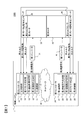
- FIG. 1 is a block diagram showing a configuration of an electric power steering system equipped with an electronic control device according to a first embodiment of the present invention. It is a figure which shows the hardware constitutions of the electronic control apparatus which concerns on the 1st Embodiment of this invention. It is a flowchart of the fail safe process in the 1st Embodiment of this invention. It is a flowchart of the communication abnormality determination in the 1st Embodiment of this invention. It is a flowchart of the reset determination in the 1st Embodiment of this invention. It is a figure explaining the method of the reset determination in the 1st Embodiment of this invention. It is a flowchart of the control state determination in the 1st Embodiment of this invention.
- FIG. 1 is a block diagram showing a configuration of an electric power steering system equipped with an electronic control device according to a first embodiment of the present invention.
- the electric power steering system 1000 shown in FIG. 1 has the same configuration and is made redundant in a first system and a second system that perform the same operation.
- the first system includes a first controller 10, a first inverter 31, a first motor 33, a first torque sensor 35, and a first motor rotation angle sensor 37.
- the second system includes a second controller 20, a second inverter 41, a second motor 43, a second torque sensor 45, and a second motor rotation angle sensor 47.
- the first controller 10 and the second controller 20 are connected to each other via a network 30 and constitute the control system 1.
- the network 30 is a transmission medium for communication signals periodically transmitted and received between the first controller 10 and the second controller 20.
- P2P communication such as SerialSPeripheral Interface (SPI), Controller Area Network (CAN).
- the communication signal is transmitted by bus communication such as
- SPI SerialSPe
- the first motor 33 and the second motor 43 are driven to rotate in accordance with the alternating currents input from the first inverter 31 and the second inverter 41, respectively, and supply a driving force for assisting or controlling the steering of the vehicle. Each generates torque.
- the first motor 33 and the second motor 43 may have a structure in which the rotor, the stator, and the winding are individually provided, or a structure in which the rotor and the stator are shared and the winding is not shared, that is, physical.
- the structure may be such that a single motor is controlled by separate windings.
- the first torque sensor 35 and the first motor rotation angle sensor 37 each output a sensor signal related to the state of the first motor 33 to the first controller 10. Specifically, the first torque sensor 35 detects the rotational torque of the first motor 33 and outputs a first torque which is a sensor signal corresponding to the detection result. The first motor rotation angle sensor 37 detects the rotor rotation angle of the first motor 33 and outputs a first motor rotation angle that is a sensor signal corresponding to the detection result. The first torque output from the first torque sensor 35 is also input to the second controller 20 for fail-safe processing described later.
- the first controller 10 is an electronic control unit (ECU) that performs various processes and calculations for realizing control of the first system in the electric power steering system 1000.
- the first controller 10 includes a first communication unit 11, a first control command generation unit 12, a first communication abnormality determination unit 13, a first reset determination unit 14, and a first control unit 15 as functions thereof.
- the first communication unit 11 transmits and receives communication signals to and from the second controller 20 via the network 30.
- This communication signal includes information for the first controller 10 and the second controller 20 to control the first motor 33 and the second motor 43 in cooperation with each other.
- the first communication unit 11 transmits a communication signal including information such as the control amount of the first motor 33 calculated by the first control command generation unit 12 from the first controller 10 to the second controller 20.
- a communication signal including information such as a control amount of the second motor 43 transmitted from the second controller 20 is received by the first communication unit 11.
- the first control command generator 12 controls the first motor 33 that is a control target based on the first torque and the first motor rotation angle respectively input from the first torque sensor 35 and the first motor rotation angle sensor 37. The amount is calculated, and a first control command corresponding to the control amount is generated and output to the first inverter 31.
- the first control command generation unit 12 is known using, for example, a steering angle signal output from a steering angle sensor (not shown) attached to a steering wheel of a vehicle, a first torque, and a first motor rotation angle.
- a target torque corresponding to the control amount of the first motor 33 is obtained by arithmetic processing.
- the first communication abnormality determination unit 13 performs communication abnormality determination that determines whether or not the communication with the second controller 20 by the first communication unit 11 is abnormal. A specific procedure for determining the communication abnormality by the first communication abnormality determination unit 13 will be described later with reference to FIG.
- the first reset determination unit 14 determines whether or not the communication abnormality is caused by the reset of the second controller 20 when the first communication abnormality determination unit 13 determines that the communication with the second controller 20 is abnormal. Perform a reset determination to determine. A specific procedure for the reset determination by the first reset determination unit 14 will be described later with reference to FIGS. 5 and 6.
- the first control unit 15 performs control state determination for determining the control mode of the first controller 10 based on the determination results of the first communication abnormality determination unit 13 and the first reset determination unit 14. A specific procedure for determining the control state by the first control unit 15 will be described later with reference to FIG.
- the first controller 10 causes an abnormality in communication performed with the second controller 20 by using the functions of the first communication abnormality determination unit 13, the first reset determination unit 14, and the first control unit 15.
- a fail-safe process is performed in which the detection is performed separately and the control mode is shifted according to the detection result. The specific procedure of the fail safe process will be described later with reference to FIG.
- the first inverter 31 performs drive control of the first motor 33 based on the first control command output from the first controller 10. For example, the switching states of a plurality of switching elements (not shown) are controlled based on the pulse width modulation signal output as the first control command from the first controller 10. Thereby, an alternating current having a predetermined amplitude, period, and phase is generated and output to the first motor 33.
- the first system can drive the first motor 33 by the operation of each component as described above.
- Each component in the second system also drives the second motor 43 by performing the same operation as each component of the first system. That is, the second torque sensor 45 and the second motor rotation angle sensor 47 detect the rotation torque and the rotor rotation angle of the second motor 43, respectively, and the second torque and the second that are sensor signals corresponding to the detection results.
- the motor rotation angle is output to the second controller 20.
- the second torque output from the second torque sensor 45 is also input to the first controller 10 for fail-safe processing.
- the second controller 20, which is an electronic control unit (ECU), functions as a second communication unit 21, a second control command generation unit 22, a second communication abnormality determination unit 23, a second reset determination unit 24, and a second control. Part 25.
- ECU electronice control unit
- the second inverter 41 performs drive control of the second motor 43 based on the second control command output from the second controller 20. As a result, the second motor 43 is driven in the second system.
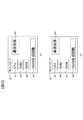
- FIG. 2 is a diagram showing a hardware configuration of the electronic control device according to the first embodiment of the present invention.
- FIG. 2A shows the hardware configuration of the first controller 10.
- the first controller 10 includes a CPU 101, a ROM 103, a RAM 105, a communication circuit 107, and a PWM generation circuit 109.
- the CPU 101 uses the RAM 105 as a work area and executes a program stored in the ROM 103, whereby the first communication unit 11, the first control command generation unit 12, the first communication abnormality determination unit 13, and the first reset determination unit 14. And the process for implement
- the communication circuit 107 operates according to the control of the CPU 101, and performs processing for transmitting a communication signal to the second controller 20 and processing for receiving a communication signal transmitted from the second controller 20.
- the communication circuit 107 implements the first communication unit 11 together with the CPU 101.
- the PWM generation circuit 109 operates in accordance with the control of the CPU 101 and performs a process of generating a pulse width modulation (PWM) signal that is output to the first inverter 31 as the first control command.
- PWM generation circuit 109 implements the first control command generation unit 12 together with the CPU 101.
- FIG. 2B shows the hardware configuration of the second controller 20.
- the second controller 20 includes a CPU 201, a ROM 203, a RAM 205, a communication circuit 207, and a PWM generation circuit 209. Since these operations are the same as those of the CPU 101, the ROM 103, the RAM 105, the communication circuit 107, and the PWM generation circuit 109 of the first controller 10, description thereof is omitted.
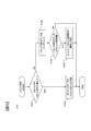
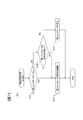
- FIG. 3 is a flowchart of fail-safe processing by the first controller 10 in the first embodiment of the present invention.
- the first controller 10 When the power of the control system 1 is turned on, the first controller 10 repeatedly executes the fail safe process shown in FIG. 3 every predetermined processing cycle.
- step S10 the first controller 10 acquires the second torque output from the second torque sensor 45. If the first controller 10 can acquire the latest value of the second torque by other processing, the processing of step S10 may be omitted by using that value. If the first motor 33 and the second motor 43 share the rotor and the stator as described above, the first torque sensor 35 outputs the second torque instead of acquiring the second torque. One torque may be acquired. In this case, the process of step S ⁇ b> 10 may be omitted by using the first torque acquired when the first control command generation unit 12 calculates the target torque of the first motor 33.
- step S ⁇ b> 11 the first controller 10 performs communication abnormality determination by the first communication abnormality determination unit 13.
- the first communication abnormality determination unit 13 performs the process shown in the flowchart of FIG. 4 to determine whether the communication between the first controller 10 and the second controller 20 is normal or abnormal. Details of the flowchart of FIG. 4 will be described later.
- step S12 the first controller 10 determines whether or not the determination result obtained by the communication abnormality determination performed in step S11 is normal communication.
- the determination result is normal communication, that is, when the determination result that the communication between the first controller 10 and the second controller 20 is normal is obtained, the fail safe process shown in FIG. 3 is terminated.
- the determination result is a communication abnormality, that is, if a determination result is obtained that the communication between the first controller 10 and the second controller 20 is abnormal, the process proceeds to step S14.
- step S14 the first controller 10 performs a reset determination by the first reset determination unit 14.
- the first reset determination unit 14 performs the process shown in the flowchart of FIG. 5 and determines whether or not the communication abnormality between the first controller 10 and the second controller 20 is due to the reset of the second controller 20. Details of the flowchart of FIG. 5 will be described later.
- step S15 the first controller 10 performs control state determination by the first control unit 15. At this time, the first control unit 15 performs the processing shown in the flowchart of FIG. 7 and determines the control mode of the first controller 10. Details of the flowchart of FIG. 7 will be described later. If the control mode of the 1st controller 10 is determined by step S15, the 1st controller 10 will complete
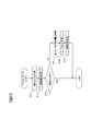
- FIG. 4 is a flowchart of communication abnormality determination by the first communication abnormality determination unit 13 in the first embodiment of the present invention.
- the first communication abnormality determination unit 13 determines whether there is a possibility of communication abnormality with the controller 20. For example, if the data in the communication signal received from the controller 20 via the network 30 is abnormal, it is determined that there is a possibility of communication abnormality, and the process proceeds to step S113.
- the presence or absence of data abnormality in the communication signal can be determined by determining the difference value between the communication signal data received last time and the communication signal data received this time, and whether or not this difference value indicates an abnormal value. it can. For example, when the difference value is 0 or out of the range of values that can be taken by normal control, it is determined that the data is abnormal, and otherwise, it is determined that the data is normal.
- step 113 when there is an error in the communication protocol or when a communication signal cannot be received from the controller 20, it is determined that there is a possibility of communication abnormality, and the process proceeds to step 113. On the other hand, if these conditions are not met, it is determined that there is no possibility of communication abnormality, and the process proceeds to step S114.
- the first communication abnormality determination unit 13 increments the communication abnormality determination counter.
- the communication abnormality determination counter is a counter for measuring a period in which it is determined that there is a possibility of communication abnormality, and is stored in the RAM 105 during the operation of the first controller 10.
- step S115 the first communication abnormality determination unit 13 determines whether or not the communication abnormality determination counter is greater than a predetermined communication abnormality determination threshold. As a result, if the communication abnormality determination counter is larger than the communication abnormality determination threshold, the process proceeds to step S117. If not, that is, if the communication abnormality determination counter is equal to or smaller than the communication abnormality determination threshold, the process proceeds to step S118.
- the communication abnormality determination threshold value used in the determination of step S115 is set in advance to a value corresponding to a time sufficient to determine that communication with the controller 20 is abnormal in consideration of the execution cycle of the failsafe process. Has been.
- the communication abnormality determination threshold can be set based on the maximum value of the communication cycle during normal operation, the maximum value of the communication interval allowed in the system, or the like.
- step S117 the first communication abnormality determination unit 13 performs communication abnormality, that is, communication between the first controller 10 and the second controller 20. Is determined to be abnormal. If step S117 is performed and the determination result with communication abnormality is obtained, the 1st communication abnormality determination part 13 will complete
- step S118 the first communication abnormality determination unit 13 determines that there is no communication abnormality, that is, the first controller 10 and the second controller 20 Is determined to be normal.
- step S118 is executed and the determination result that there is no communication abnormality is obtained, the first communication abnormality determination unit 13 ends the communication abnormality determination shown in FIG.
- step S114 the first communication abnormality determination unit 13 clears the above-described communication abnormality determination counter to an initial value (for example, 0). Thereafter, after performing the above-described processing in step S118, the communication abnormality determination shown in FIG.
- the first communication abnormality determination unit 13 can determine whether the communication between the first controller 10 and the second controller 20 is normal or abnormal by performing the communication abnormality determination as described above. .
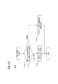
- FIG. 5 is a flowchart of the reset determination by the first reset determination unit 14 in the first embodiment of the present invention.
- step S141 the first reset determination unit 14 determines whether or not the second torque acquired in step S10 satisfies a predetermined reset condition. As a result, if it is determined that the reset condition is satisfied, the process proceeds to step S143. If it is determined that the reset condition is not satisfied, the process proceeds to step S145.
- determination of step S141 is performed using the 2nd torque. Moreover, what is necessary is just to determine in step S141 whether the 1st torque satisfy
- the reset condition used in the determination in step S141 is that the second controller 20 outputs the second torque to be output from the second torque sensor 45 when the second controller 20 is reset and the control of the second motor 43 is stopped. It is preset according to the change in value.
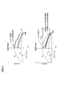
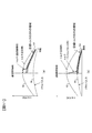
- the reset determination method in step S141 in the first embodiment of the present invention will be described with reference to FIG. 6, taking as an example the case where the reset determination region D1 shown in FIG. 6 is used as a reset condition.
- a waveform 61 represents the steering input torque by the vehicle driver
- a waveform 62 represents the normal output torque output by the second motor 43 with respect to this input torque. For example, a region near 50% of the normal output torque is set in the reset determination region D1.
- FIG. 6A is a diagram illustrating a state of change in the second torque when the second controller 20 is not reset when a communication abnormality is detected by the first communication abnormality determination unit 13.
- the communication between the first controller 10 and the second controller 20 becomes abnormal, cooperative control is impossible, but the control of the second motor 43 by the second controller 20 is continuously performed. Therefore, as shown by the broken line, the second torque fluctuates in the vicinity of the normal output torque indicated by the waveform 62, but does not decrease greatly from there. Therefore, it is determined that the second torque does not reach the reset determination region D1 and does not satisfy the reset condition in step S141.
- FIG. 6B is a diagram illustrating a change in the second torque when the second controller 20 is reset when a communication abnormality is detected by the first communication abnormality determination unit 13.
- the second system in the electric power steering system 1000 is stopped and the second torque is rapidly reduced.
- the first system is a redundant system. Since the first motor 33 is driven, the second torque is not completely zero, and about half of the normal output torque is detected as the second torque. As a result, as indicated by a broken line, the second torque changes to be within the reset determination region D1, and it is determined in step S141 that the reset condition is satisfied.
- an area other than around 50% of the normal output torque may be set.
- the second controller 20 is reset.
- the second torque becomes zero. Therefore, in such a case, an area near 0% of the normal output torque may be set as the reset determination area D1.
- the reset determination area D1 can be set.
- a region other than the reset determination region D1 shown in FIG. 6 may be used as the reset condition.
- the reset condition is that the amount of change (decrease amount) of the second torque per predetermined unit time exceeds a predetermined threshold.
- the determination in step S141 can be made based on whether the reset condition is satisfied. Alternatively, paying attention to the fact that the second torque continuously decreases when the second motor 43 is stopped, whether or not the reset condition satisfies the reset condition that the second torque monotonously decreases within a predetermined determination time.
- the determination in step S141 can also be made depending on whether or not. In addition to this, in consideration of a change in the second torque when the cooperative control is not performed due to communication abnormality and a change in the second torque when the second motor 43 is stopped while the first motor 33 is being driven, Reset judgment conditions can be set.
- step S143 the first reset determination unit 14 determines that the second controller 20 has been reset. Thereby, it is determined that the cause of the communication abnormality between the first controller 10 and the second controller 20 detected by the first communication abnormality determination unit 13 in the communication abnormality determination of step S11 is the reset of the second controller 20. Results are obtained. If step S143 is performed, the 1st reset determination part 14 will complete
- step S145 the first reset determination unit 14 increments the reset determination counter.
- the reset determination counter is a counter for measuring a period during which it is determined that the second torque does not satisfy the reset condition, and is stored in the RAM 105 during the operation of the first controller 10. That is, even when the second controller 20 is reset and the control of the second motor 43 is stopped, as shown in FIG. 6B, until the second torque reaches the reset determination region D1. Since it takes a certain amount of time, the second torque does not always satisfy the reset condition at the time of step S141. Therefore, when the second torque does not satisfy the reset condition, the time is measured by the reset determination counter.
- step S147 the first reset determination unit 14 determines whether or not the reset determination counter is greater than a predetermined reset determination threshold value. As a result, if the reset determination counter is larger than the reset determination threshold, the process proceeds to step S149. If not, that is, if the reset determination counter is equal to or smaller than the reset determination threshold, the reset determination shown in FIG. Note that the reset determination threshold used in the determination of step S147 is determined that the controller 20 is not reset in consideration of the time until the reset condition is satisfied due to the reset of the second controller 20 affecting the second torque. A value corresponding to a sufficient time to do is set in advance.
- step S149 the first reset determination unit 14 determines whether the network 30 is abnormal or the first communication unit 11 of the first controller 10 And at least one of the second communication units 21 of the second controller 20 is determined to be abnormal. Thereby, the cause of the communication abnormality between the first controller 10 and the second controller 20 detected by the first communication abnormality determination unit 13 in the communication abnormality determination of step S11 is not the reset of the second controller 20, but the communication system. It is possible to obtain a determination result that the abnormality is If step S149 is performed, the 1st reset determination part 14 will complete
- the first reset determination unit 14 When the communication between the first controller 10 and the second controller 20 is abnormal, the first reset determination unit 14 performs a reset determination as described above, thereby providing a sensor signal related to the state of the second motor 43. Whether or not the second controller 20 has been reset can be determined based on the change in the second torque.
- FIG. 7 is a flowchart of control state determination by the first control unit 15 in the first embodiment of the present invention.
- step S151 the first controller 15 determines whether or not the second controller 20 has been reset based on the reset determination result in step S14. If it is determined that the second controller 20 has been reset by executing step S143 in the reset determination, the process proceeds to step S153. On the other hand, if step S149 is executed in the reset determination and a determination result that the second controller 20 is not reset is obtained, the process proceeds to step S157. If neither step S143 nor step S149 is executed in the reset determination, that is, if it is determined in step S147 that the reset determination counter is equal to or smaller than the reset determination threshold, the process of step S151 is not performed. It is preferable to end the control state determination shown in FIG.
- step S153 the first controller 15 determines the control state of the first controller 10 so that the operation of the first controller 10 is continued and the control of the first motor 33 is continued. Thus, when the second system stops in the electric power steering system 1000, the operation of the first system is continued to prevent the entire system from stopping. If step S153 is performed, the 1st control part 15 will complete
- step S155 the first controller 15 compares the priority of the first controller 10 with the priority of the second controller 20, It is determined whether or not the priority of one controller 10 is higher. As a result, if it is determined that the priority of the first controller 10 is higher, the process proceeds to step S153. If not, that is, if it is determined that the priority of the second controller 20 is higher, the process proceeds to step S153. Proceed to S157.
- the first controller 10 and the second controller 20 each have a preset priority according to the priority of control continuation, and both priorities are stored.
- step S155 If it is determined in step S155 that the priority of the first controller 10 is higher, the first controller 15 executes step S153, as in the case where it is determined in step S151 that the second controller 20 has been reset. Thus, the operation of the first controller 10 is continued and the control of the first motor 33 is continued.
- step S157 the first controller 15 stops the operation of the first controller 10 and controls the first motor 33. The control state of the first controller 10 is determined so as not to be performed. As a result, the output of the first control command from the first control command generator 12 is stopped in the first controller 10, and the drive control of the first motor 33 by the first inverter 31 is not performed. Thereby, in the electric power steering system 1000, when the second system is operating and the priority of the second system is high, the operation of the first system is stopped. If step S157 is performed, the 1st control part 15 will complete
- the first control unit 15 can continue the operation of the first controller 10 when the second controller 20 is reset by performing the control state determination as described above. Moreover, when the 2nd controller 20 is not reset, it can be determined according to the priority of the 1st controller 10 and the 2nd controller 20 whether the 1st controller 10 is stopped. That is, since the first controller 10 and the second controller 20 execute the same fail-safe process, if the cause of the communication abnormality between them is other than the reset of one controller, the communication is performed at the same timing. An abnormality may be detected. Therefore, if the first controller 10 and the second controller 20 stop their operations without considering the priority, the entire control system 1 stops.
- the first controller 10 and the second controller 20 determine whether or not to stop their operations in consideration of the respective priorities, whereby the first controller 10 and the second controller 10 in the control system 1 are determined. Only one of the controllers 20 is stopped. That is, the control system 1 determines that the first reset determination unit 14 determines that the second controller 20 is not reset, and the first controller 20 determines that the first controller 10 is not reset. Based on the priority set in advance for each of the controller 10 and the second controller 20, either the control of the first motor 33 by the first controller 10 or the control of the second motor 43 by the second controller 20 is performed. Stop. As a result, in the electric power steering system 1000, it is possible to avoid the entire system from stopping.
- the first controller 10 when a communication abnormality occurs with the second controller 20, it is possible to immediately distinguish and determine the cause of the communication abnormality. That is, whether the communication abnormality with respect to the second controller 20 has occurred due to an abnormality in the communication system such as the network 30 or the mutual communication function, or whether the second controller 20 of the communication partner has been reset. The determination can be made without waiting until the controller 20 returns from the reset state. If the time until the second controller 20 returns from the reset state elapses, the first controller 10 checks whether or not the communication state after the return is normal, thereby fail-safe processing described in the present embodiment. It is also possible to determine the cause of the communication abnormality without performing the process.
- the first controller 10 needs to wait at least a time until the second controller 20 returns from the reset state in order to determine the cause of the communication abnormality.
- the cause of the communication abnormality can be determined in the first controller 10 without waiting until the second controller 20 returns from the reset state. Therefore, it is possible to make a determination faster than in the past.
- the first controller 10 can immediately determine its own control mode in response to the result of the reset determination by the first reset determination unit 14.
- the second controller 20 can immediately determine its own control mode. For this reason, the entire system of the electric power steering system 1000, that is, the state where both the first system and the second system are stopped simultaneously, and the situation where the control of the first system and the second system are performed asynchronously, respectively. Can be avoided.
- the first controller 10 that is an electronic control device generates a first control command for controlling the first motor 33 that is the first control target, and outputs the first control command 12.
- the first communication unit 11 that communicates with the second controller 20 that is another electronic control device for controlling the second motor 43 that is the second control target, and the first communication unit 11 communicates with the second controller 20.
- a first reset determination unit that determines whether or not the second controller 20 has been reset based on a change in the second torque that is a sensor signal relating to the state. Since it did in this way, when a communication abnormality generate
- the first reset determination unit 14 determines that the second controller 20 has been reset when the second torque changes and falls within the predetermined reset determination region D1 in steps S141 and S143. It can also be determined that the second controller 20 has been reset when the amount of change in the second torque per predetermined unit time exceeds a predetermined threshold. Furthermore, it can also be determined that the second controller 20 has been reset when the second torque monotonously decreases within a predetermined determination time. Since it did in this way, the change of the 2nd torque when the cooperation control is not performed due to communication abnormality and the change of the 2nd torque when the 2nd motor 43 stops during the drive of the 1st motor 33 is considered. It is possible to appropriately determine whether or not the second controller 20 has been reset.
- the first control command generation unit 12 continues to output the first control command when the first reset determination unit 14 determines that the second controller 20 has been reset in steps S151 and S153. Since it did in this way, when the 2nd controller 20 is reset, control of the 1st motor 33 by the 1st controller 10 can be continued, and it can prevent that the electric power steering system 1000 stops.
- FIG. 8 is a block diagram showing a configuration of an electric power steering system equipped with an electronic control device according to the second embodiment of the present invention.
- the electric power steering system 1001 illustrated in FIG. 8 includes the first controller 10 and the second controller 20 in the control system 1 illustrated in FIG. Is different from the first controller 10A and the second controller 20A.
- the first controller 10A functionally includes a first control command generation unit 12A and a first reset determination unit 14A instead of the first control command generation unit 12 and the first reset determination unit 14 in FIG.
- the second controller 20A functionally includes a second control command generation unit 22A and a second reset determination unit 24A instead of the second control command generation unit 22 and the second reset determination unit 24 of FIG. ing. Since points other than this are the same as those in the first embodiment, description thereof will be omitted below.
- the first controller 10A and the second controller 20A each perform fail-safe processing according to a procedure different from that described in the first embodiment.
- the first control command generator 12A and the second control command generator 22A are controlled when it is determined that the communication between the first controller 10A and the second controller 20A is abnormal.
- the control amounts of the first motor 33 and the second motor 43 are limited.
- the first reset determination unit 14A and the second reset determination unit 24A each perform reset determination by a procedure different from that described in the first embodiment. Since the operations of the first controller 10A and the second controller 20A are the same, only the operation of the first controller 10A will be described below, and the description of the operation of the second controller 20A will be omitted.
- FIG. 9 is a flowchart of fail-safe processing by the first controller 10A in the second embodiment of the present invention.
- the first controller 10A When the power of the control system 1A is turned on, the first controller 10A repeatedly executes the fail safe process shown in FIG. 9 every predetermined processing cycle.
- steps S10 to S12 and S15 have the same processing contents as in FIG.
- steps S13 and S14A different from FIG. 3 will be described.
- the first controller 10A limits the control amount of the first motor 33 in step S13.
- the control amount of the first motor 33 is limited by limiting the first control command output from the first control command generator 12A to the first inverter 31 to a value lower than normal.
- the output torque of the first motor 33 is X% (for example, 25%) of the target torque of the first motor 33 determined based on the steering angle signal, the first torque, and the first motor rotation angle.
- the first control command generator 12 generates a first control command and outputs the first control command to the first inverter 31.
- control amount of the first motor 33 may be limited by another method, for example, a predetermined control amount is output as the first control command regardless of the target torque. If step S13 is performed, the 1st controller 10A will advance a process to step S14A.
- step S14A the first controller 10A performs a reset determination by the first reset determination unit 14A.
- the first reset determination unit 14A performs the process shown in the flowchart of FIG. 10, and determines whether or not the communication abnormality between the first controller 10A and the second controller 20A is caused by the reset of the second controller 20A.
- FIG. 10 is a flowchart of the reset determination by the first reset determination unit 14A in the second embodiment of the present invention.
- the first reset determination unit 14A determines whether the second torque acquired in step S10 is normal or reset. As a result, if it is determined that the second torque matches at the time of reset, the process proceeds to step S143. If it is determined that the second torque matches at the normal time, the process proceeds to step S149.
- the second torque is used. The determination in step S141A is performed. If the first torque is acquired instead of acquiring the second torque as described above, it may be determined in step S141A whether the first torque matches the normal time or the reset time.
- the determination in step S141A takes into account the control amount of the first motor 33 restricted in step S13 of FIG. 9 and the control amount of the second motor 43 restricted in the same manner, and the second torque becomes after the restriction. This is performed by determining whether or not the motor control amount is met.
- FIG. 11 for the reset determination method in step S141A in the second embodiment of the present invention, taking as an example the case where the output torque of the first motor 33 is limited to X% of the target torque as described above.
- the waveform 61 represents the steering input torque by the driver of the vehicle
- the waveform 62 is output by the second motor 43 in response to this input torque. It represents the output torque at normal time.
- FIG. 11A is a diagram illustrating a state of change in the second torque when the second controller 20A is not reset when a communication abnormality is detected by the first communication abnormality determination unit 13.
- the output torque of the first motor 33 is limited to X% of the target torque in the first controller 10A, and the control of the second motor 43 by the second controller 20A is continuously performed.
- the output torque of the second motor 43 is limited to X% of the target torque. Therefore, as indicated by a broken line, a value of 2X% of the target torque is detected as the second torque.
- a value in the vicinity of 2X% of the target torque is set in the normal determination region D2, it is determined in step S141A that the second torque is in a normal state because the second torque is within the normal determination region D2. Is done.
- FIG. 11B is a diagram illustrating a state of change in the second torque when the second controller 20 ⁇ / b> A is reset when a communication abnormality is detected by the first communication abnormality determination unit 13.
- the second system is stopped in the electric power steering system 1001, and the second torque is rapidly reduced.
- the first motor 33 of the first system which is a redundant system, is driven, and its output torque is limited to X% of the target torque. Therefore, the second torque is not completely zero as indicated by the broken line, and the value of X% of the normal output torque is detected as the second torque.
- a value in the vicinity of X% of the target torque is set in the reset determination region D3, it is determined in step S141A that the second torque is matched at the time of reset because the second torque falls within the reset determination region D3. Is done.
- the normal determination area D2 and the reset determination area D3 may be set to areas other than those illustrated in FIG. 11 as in the reset determination area D1 in the first embodiment. Changes in the second torque due to the control amount of the first motor 33 and the second motor 43 being limited in the first controller 10A and the second controller 20A, and the second motor 43 stopped during the driving of the first motor 33
- the normal determination area D2 and the reset determination area D3 can be set in consideration of the change in the second torque in the case.
- step S143 the first reset determination unit 14A determines that the second controller 20 has been reset. Thereby, it is determined that the cause of the communication abnormality between the first controller 10A and the second controller 20A detected by the first communication abnormality determination unit 13 in the communication abnormality determination in step S11 is the reset of the second controller 20A. Results are obtained. If step S143 is performed, 14 A of 1st reset determination parts will complete
- step S149 the first reset determination unit 14A determines whether the network 30 is abnormal or the first communication unit 11 of the first controller 10A. It is determined that at least one of the second communication units 21 of the second controller 20A is abnormal. Thereby, the cause of the communication abnormality between the first controller 10A and the second controller 20A detected by the first communication abnormality determination unit 13 in the communication abnormality determination in step S11 is not the reset of the second controller 20A but the communication system. It is possible to obtain a determination result that the abnormality is. If step S149 is performed, the 1st reset determination part 14A will complete
- the first control command generation unit 12A when the first communication abnormality determination unit 13 determines that the communication with the second controller 20A is abnormal, In step S13, the control amount of the first motor 33 in the first control command is limited. Further, the first reset determination unit 14A determines that the second controller 20A has not been reset when the amount of change in the second torque matches the control amount after the limitation in steps S141A and S149. Since it did in this way, it can prevent that the driver
- FIG. 12 is a block diagram showing a configuration of an electric power steering system equipped with an electronic control device according to the third embodiment of the present invention.
- the electric power steering system 1002 illustrated in FIG. 12 includes the first controller 10 and the second controller 20 in the control system 1 illustrated in FIG. Are different from the first controller 10B and the second controller 20B in that the first torque is not output from the first torque sensor 35 to the second controller 20B.
- the first controller 10B functionally includes a first control unit 15B instead of the first control unit 15 in FIG.
- the second controller 20B functionally includes only the second communication unit 21 and the second control command generation unit 22, and the second communication abnormality determination unit 23, the second reset determination unit 24, and the second control unit 22 of FIG.
- the control unit 25 is not provided. That is, the second controller 20B of the present embodiment has a communication function with the first controller 10B and a control function of the second motor 43, but does not have a fail-safe function based on the first torque. Since points other than this are the same as those in the first embodiment, description thereof will be omitted below.
- the first controller 10B performs fail-safe processing according to a procedure different from that described in the first embodiment.
- the first control unit 15B performs control state determination determination according to a procedure different from that described in the first embodiment.
- FIG. 13 is a flowchart of fail-safe processing by the first controller 10B in the third embodiment of the present invention.
- the first controller 10B When the power of the control system 1B is turned on, the first controller 10B repeatedly executes the fail safe process shown in FIG. 13 every predetermined processing cycle.
- steps S10 to S14 have the same processing contents as in FIG.
- step S15B different from FIG. 3 will be described.
- the first controller 10B When the reset determination by the first reset determination unit 14 is performed in step S14, the first controller 10B performs control state determination by the first control unit 15B in step S15B. At this time, the first controller 15B performs the process shown in the flowchart of FIG. 14 to determine the control mode of the first controller 10B.
- FIG. 14 is a flowchart of control state determination by the first controller 15B in the third embodiment of the present invention.
- the first control unit 15B determines whether or not the second controller 20B has been reset based on the reset determination result in step S14. If the determination result that the second controller 20B is reset is obtained by executing step S143 in the reset determination, the operation of the first controller 10B is continued in step S153 as in the first embodiment. Thus, the control state of the first controller 10B is determined so as to continue the control of the first motor 33. Thereafter, the first control unit 15B ends the control state determination shown in FIG.
- step S149 is executed in the reset determination and a determination result that the second controller 20B is not reset is obtained, the process proceeds to step S157. That is, in this case, unlike the first embodiment, the operation of the first controller 10B is stopped and the first motor 33 is not controlled in step 157 without executing the determination in step S155 of FIG. As described above, the control state of the first controller 10B is determined. Thereafter, the first control unit 15B ends the control state determination shown in FIG.
- the first control unit 15B performs the control state determination as described above, so that when the second controller 20B is reset, the operation of the first controller 10B is continued as in the first embodiment. be able to.
- the second controller 20B is not reset, unlike the first embodiment, the first controller 10B is stopped and the output of the first control command from the first control command generator 12 is stopped. be able to. That is, in the present embodiment, the second controller 20B does not execute the fail-safe process, so even when a communication abnormality occurs between these controllers by resetting the first controller 10B, the operation of the second controller 20B Will never be stopped. Therefore, in such a case, by stopping the operation of the first controller 10B, in the electric power steering system 1002, control that is not intended by the driver of the vehicle at the time of communication abnormality is performed while preventing the entire system from stopping. Can be prevented.
- the first control command generator 12 determines that the second controller 20B has not been reset by the first reset determiner 14 in steps S151 and S157. In this case, the output of the first control command is stopped. On the other hand, in Steps S151 and S153, when the first reset determination unit 14 determines that the second controller 20B has been reset, the output of the first control command is continued. Since it did in this way, when the communication abnormality is detected between the 1st controller 10B and the 2nd controller 20B, according to the cause of the communication abnormality, control of the 1st motor 33 by the 1st controller 10B is continued. It is possible to appropriately determine whether or not.
- the number of controllers connected to the network 30 and communicating with each other is not limited to two, and may be three or more.
- the reset determination region D1 in the first embodiment is set to a region near 1 / N of the normal motor output torque according to the number of controllers. Is preferred.
- the motor output torque after the limitation in the second embodiment is also preferably set according to the number of controllers.
- the first controller 15 of the first controller 10, 10A and the second controller 25 of the second controller 20, 20A determine the control state of FIG. In the above example, when these controllers are not reset, one controller is stopped according to each priority.
- a control circuit different from the first controller 10, 10A and the second controller 20, 20A may be provided in the control system 1, 1A, and it may be determined which controller is to be stopped in this control circuit. .
- the controller In each of the embodiments described above, an example in which the first motor 33 and the second motor 43 that generate driving force for assisting or controlling the steering of the vehicle in the electric power steering system are controlled by the controller has been described.
- other objects may be controlled by the controller.
- various objects can be controlled as long as they are used in a redundant system of a plurality of systems such as a vehicle travel motor, a brake actuator, and various actuators mounted on a system other than the vehicle.
- the reset condition in step S141 described in the first embodiment and the determination condition in step S141A described in the second embodiment are set according to this control target.
- the amount of change of the sensor signal that is, the increase amount exceeds a predetermined threshold, or the sensor signal is detected within a predetermined determination time.
- the determination in step S141 is performed depending on whether these reset conditions are satisfied. As a result, when these reset conditions are satisfied, it can be determined in one controller that the other controller has been reset.
Landscapes
- Engineering & Computer Science (AREA)
- Automation & Control Theory (AREA)
- Transportation (AREA)
- Mechanical Engineering (AREA)
- Human Computer Interaction (AREA)
- General Physics & Mathematics (AREA)
- Physics & Mathematics (AREA)
- Chemical & Material Sciences (AREA)
- Combustion & Propulsion (AREA)
- Aviation & Aerospace Engineering (AREA)
- Radar, Positioning & Navigation (AREA)
- Remote Sensing (AREA)
- Steering Control In Accordance With Driving Conditions (AREA)
- Power Steering Mechanism (AREA)
- Safety Devices In Control Systems (AREA)
Abstract
電子制御装置は、第一の制御対象を制御するための制御指令を生成して出力する制御指令生成部と、第二の制御対象を制御する他の電子制御装置と通信を行う通信部と、前記通信部による前記他の電子制御装置との通信が異常であるか否かを判定する通信異常判定部と、前記通信異常判定部により前記他の電子制御装置との通信が異常であると判定された場合に、前記第二の制御対象の状態に関するセンサ信号の変化に基づいて、前記他の電子制御装置がリセットされたか否かを判定するリセット判定部と、を備える。
Description
本発明は、電子制御装置と、これを用いた制御システムおよびリセット判定方法に関する。
自動車分野では、車両に搭載された各種アクチュエータの制御を行う電子制御装置(ECU)が利用されている。この電子制御装置には、故障が発生した際の車両事故などのリスクを低減するために所定の安全設計が要求されている。たとえば、自動運転車両におけるステアリングやブレーキの制御を行う制御システムでは、故障発生時にも制御を継続してドライバの安全性を確保できるようにするため、相互に通信を行う複数の電子制御装置を利用した冗長化構成が広く採用されている。
上記のような冗長化構成の制御システムにおいて、電子制御装置間に通信異常が発生した場合には、その後の制御モードを適切に決定するために、通信異常の原因が通信機能の故障であるか、それとも一方の電子制御装置がリセット状態になったことであるかを直ちに判断する必要がある。これに関して、特許文献1には、2つの電子制御装置にそれぞれ搭載されたマイコン間で通信途絶状態が発生した場合に、所定時間以内にその通信途絶状態が解消されたか否かを判定することで、マイコンの異常と通信線の異常とを区別して検出する技術が開示されている。
特許文献1に開示された技術では、マイコンがリセット状態から立ち上がって通信を再開するのに要する時間が経過するまでは、マイコンの異常と通信線の異常とを区別することができない。そのため、通信異常の原因を直ちに判断することができない。
本発明の第1の態様による電子制御装置は、第一の制御対象を制御するための制御指令を生成して出力する制御指令生成部と、第二の制御対象を制御する他の電子制御装置と通信を行う通信部と、前記通信部による前記他の電子制御装置との通信が異常であるか否かを判定する通信異常判定部と、前記通信異常判定部により前記他の電子制御装置との通信が異常であると判定された場合に、前記第二の制御対象の状態に関するセンサ信号の変化に基づいて、前記他の電子制御装置がリセットされたか否かを判定するリセット判定部と、を備える。
本発明の第2の態様による制御システムは、電子制御装置および他の電子制御装置を備え、前記他の電子制御装置は、前記電子制御装置との通信が異常である場合に、前記電子制御装置がリセットされたか否かを判定する第二のリセット判定部を有しており、前記他の電子制御装置がリセットされていないと前記リセット判定部が判定し、かつ前記電子制御装置がリセットされていないと前記第二のリセット判定部が判定した場合に、前記電子制御装置と前記他の電子制御装置のそれぞれに対して予め設定された優先度に基づいて、前記電子制御装置による前記第一の制御対象の制御または前記他の電子制御装置による前記第二の制御対象の制御のいずれか一方を停止させる。
本発明の第3の態様によるリセット判定方法は、相互に通信を行う第一の電子制御装置および第二の電子制御装置を有する制御システムにおいて、前記第一の電子制御装置により、前記第二の電子制御装置との通信が異常であるか否かを判定し、前記第二の電子制御装置との通信が異常であると判定された場合に、前記第一の電子制御装置により、前記第二の電子制御装置の制御対象の状態に関するセンサ信号の変化に基づいて、前記第二の電子制御装置がリセットされたか否かを判定する。
本発明によれば、電子制御装置間に通信異常が発生した場合に、その原因を直ちに判断することができる。
(第1の実施形態)
以下、図1~図7を用いて、本発明の第1の実施形態に係る電子制御装置について説明する。本実施形態では、車両のステアリングをアシストまたは制御する電動パワーステアリングシステムに搭載された電子制御装置を例として、本発明の説明を行う。
以下、図1~図7を用いて、本発明の第1の実施形態に係る電子制御装置について説明する。本実施形態では、車両のステアリングをアシストまたは制御する電動パワーステアリングシステムに搭載された電子制御装置を例として、本発明の説明を行う。
図1は、本発明の第1の実施形態に係る電子制御装置を搭載した電動パワーステアリングシステムの構成を示すブロック図である。図1に示す電動パワーステアリングシステム1000は、同様の構成であり同様の動作を行う第1系統と第2系統に冗長化されている。第1系統は、第1コントローラ10、第1インバータ31、第1モータ33、第1トルクセンサ35、および第1モータ回転角センサ37を備える。第2系統は、第2コントローラ20、第2インバータ41、第2モータ43、第2トルクセンサ45、および第2モータ回転角センサ47を備える。第1コントローラ10と第2コントローラ20は、ネットワーク30を介して互いに接続されており、制御システム1を構成している。ネットワーク30は、第1コントローラ10と第2コントローラ20の間で定期的に送受信される通信信号の伝送媒体であり、たとえば、Serial Peripheral Interface(SPI)のようなP2P通信や、Controller Area Network(CAN)のようなバス通信により、通信信号の伝送を行う。
第1モータ33および第2モータ43は、第1インバータ31、第2インバータ41からそれぞれ入力される交流電流に応じて回転駆動し、車両のステアリングをアシストまたは制御するための駆動力を供給する回転トルクをそれぞれ発生する。なお、第1モータ33と第2モータ43とは、ロータ、ステータおよび巻線を個別にそれぞれ有する構造であってもよいし、ロータとステータを共有して巻線を共有しない構造、すなわち物理的には単一のモータを別々の巻線で制御するような構造であってもよい。
第1系統において、第1トルクセンサ35および第1モータ回転角センサ37は、第1モータ33の状態に関するセンサ信号を第1コントローラ10にそれぞれ出力する。具体的には、第1トルクセンサ35は、第1モータ33の回転トルクを検出し、その検出結果に応じたセンサ信号である第1トルクを出力する。第1モータ回転角センサ37は、第1モータ33のロータ回転角を検出し、その検出結果に応じたセンサ信号である第1モータ回転角を出力する。なお、第1トルクセンサ35から出力された第1トルクは、後述するフェイルセーフ処理のために第2コントローラ20にも入力される。
第1コントローラ10は、電動パワーステアリングシステム1000において第1系統の制御を実現するための各種の処理や演算を行う電子制御装置(ECU)である。第1コントローラ10は、その機能として、第1通信部11、第1制御指令生成部12、第1通信異常判定部13、第1リセット判定部14および第1制御部15を有する。
第1通信部11は、ネットワーク30を介して第2コントローラ20との間で通信信号の送受信を行う。この通信信号には、第1コントローラ10と第2コントローラ20とが第1モータ33と第2モータ43をそれぞれ協調して制御するための情報が含まれる。たとえば、第1制御指令生成部12で演算された第1モータ33の制御量などの情報を含む通信信号が、第1コントローラ10から第2コントローラ20へと第1通信部11により送信される。また、第2コントローラ20から送信された第2モータ43の制御量などの情報を含む通信信号が、第1通信部11により受信される。
第1制御指令生成部12は、第1トルクセンサ35と第1モータ回転角センサ37からそれぞれ入力された第1トルクおよび第1モータ回転角に基づいて、制御対象である第1モータ33の制御量を演算し、その制御量に応じた第1制御指令を生成して第1インバータ31に出力する。第1制御指令生成部12は、たとえば、車両のステアリングホイールに取り付けられた不図示の舵角センサから出力される舵角信号と、第1トルクおよび第1モータ回転角とを用いて、周知の演算処理により、第1モータ33の制御量に応じた目標トルクを求める。このとき、前述の通信信号により第2コントローラ20から送信された第2モータ43の制御量、すなわち第2モータ43の目標トルクを考慮して、第1モータ33の目標トルクを決定することで、第1コントローラ10と第2コントローラ20との間で協調制御が実現される。そして、求められた目標トルクに応じたパルス幅変調(PWM)信号を生成し、第1制御指令として第1インバータ31に出力する。なお、第1制御指令生成部12による第1モータ33の目標トルクの演算結果は、前述の通信信号により、第1通信部11からネットワーク30を介して第2コントローラ20に送信される。
第1通信異常判定部13は、第1通信部11による第2コントローラ20との通信が異常であるか否かを判定する通信異常判定を実施する。なお、第1通信異常判定部13による通信異常判定の具体的な手順については、後で図4を参照して説明する。
第1リセット判定部14は、第1通信異常判定部13により第2コントローラ20との通信が異常であると判定された場合に、その通信異常が第2コントローラ20のリセットによるものか否かを判定するリセット判定を実施する。なお、第1リセット判定部14によるリセット判定の具体的な手順については、後で図5および図6を参照して説明する。
第1制御部15は、第1通信異常判定部13および第1リセット判定部14の判定結果に基づいて第1コントローラ10の制御モードを決定する制御状態決定を実施する。なお、第1制御部15による制御状態決定の具体的な手順については、後で図7を参照して説明する。
第1コントローラ10は、上記の第1通信異常判定部13、第1リセット判定部14および第1制御部15の各機能を用いて、第2コントローラ20との間で行われる通信の異常を原因ごとに区別して検出し、その検出結果に応じた制御モードに移行するフェイルセーフ処理を行う。なお、フェイルセーフ処理の具体的な手順については、後で図3を参照して説明する。
第1インバータ31は、第1コントローラ10から出力された第1制御指令に基づき、第1モータ33の駆動制御を行う。たとえば、第1コントローラ10から第1制御指令として出力されたパルス幅変調信号に基づき、不図示の複数のスイッチング素子のスイッチング状態をそれぞれ制御する。これにより、所定の振幅、周期、位相を有する交流電流を生成して、第1モータ33に出力する。
電動パワーステアリングシステム1000において、第1系統は、以上説明したような各構成要素の動作により、第1モータ33を駆動させることができる。
第2系統における各構成要素も、第1系統の各構成要素とそれぞれ同様の動作を行うことで、第2モータ43を駆動させる。すなわち、第2トルクセンサ45および第2モータ回転角センサ47は、第2モータ43の回転トルクとロータ回転角をそれぞれ検出し、これらの検出結果に応じたセンサ信号である第2トルクと第2モータ回転角を第2コントローラ20にそれぞれ出力する。なお、第2トルクセンサ45から出力された第2トルクは、フェイルセーフ処理のために第1コントローラ10にも入力される。電子制御装置(ECU)である第2コントローラ20は、その機能として、第2通信部21、第2制御指令生成部22、第2通信異常判定部23、第2リセット判定部24および第2制御部25を有している。これらは、第1コントローラ10の第1通信部11、第1制御指令生成部12、第1通信異常判定部13、第1リセット判定部14、第1制御部15とそれぞれ対応しており、同じ動作をそれぞれ行う。第2インバータ41は、第2コントローラ20から出力された第2制御指令に基づき、第2モータ43の駆動制御を行う。これにより、第2系統において第2モータ43が駆動される。
図2は、本発明の第1の実施形態に係る電子制御装置のハードウェア構成を示す図である。図2(a)は、第1コントローラ10のハードウェア構成を示している。図2(a)に示すように、第1コントローラ10は、CPU101、ROM103、RAM105、通信回路107、およびPWM生成回路109を備える。CPU101は、RAM105を作業領域に用いてROM103に保存されたプログラムを実行することで、第1通信部11、第1制御指令生成部12、第1通信異常判定部13、第1リセット判定部14および第1制御部15の各機能を実現するための処理を行う。通信回路107は、CPU101の制御に応じて動作し、第2コントローラ20へ通信信号を送信する処理と、第2コントローラ20から送信された通信信号を受信する処理を行う。通信回路107は、CPU101と共に第1通信部11を実現する。PWM生成回路109は、CPU101の制御に応じて動作し、第1インバータ31に第1制御指令として出力するパルス幅変調(PWM)信号を生成する処理を行う。PWM生成回路109は、CPU101と共に第1制御指令生成部12を実現する。
図2(b)は、第2コントローラ20のハードウェア構成を示している。図2(b)に示すように、第2コントローラ20は、CPU201、ROM203、RAM205、通信回路207、およびPWM生成回路209を備える。これらの動作は、第1コントローラ10のCPU101、ROM103、RAM105、通信回路107、およびPWM生成回路109とそれぞれ同様であるため、説明を省略する。
次に、第1コントローラ10が行うフェイルセーフ処理について説明する。図3は、本発明の第1の実施形態における第1コントローラ10によるフェイルセーフ処理のフローチャートである。第1コントローラ10は、制御システム1の電源が投入されると、図3に示すフェイルセーフ処理を所定の処理周期ごとに繰り返し実行する。
ステップS10において、第1コントローラ10は、第2トルクセンサ45から出力された第2トルクを取得する。なお、他の処理で第1コントローラ10が第2トルクの最新値を取得可能であれば、その値を用いることでステップS10の処理を省略してもよい。また、前述のように第1モータ33と第2モータ43がロータとステータを共有している構造である場合には、第2トルクを取得する代わりに、第1トルクセンサ35から出力された第1トルクを取得してもよい。この場合、第1制御指令生成部12が第1モータ33の目標トルクを演算する際に取得した第1トルクを用いることで、ステップS10の処理を省略してもよい。
ステップS11において、第1コントローラ10は、第1通信異常判定部13による通信異常判定を行う。このとき第1通信異常判定部13は、図4のフローチャートに示す処理を行い、第1コントローラ10と第2コントローラ20の間の通信が正常であるか異常であるかを判定する。なお、図4のフローチャートの詳細については後で説明する。
ステップS12において、第1コントローラ10は、ステップS11で行った通信異常判定により得られた判定結果が通信正常であるか否かを判定する。判定結果が通信正常である場合、すなわち第1コントローラ10と第2コントローラ20の間の通信が正常であるとの判定結果が得られた場合は、図3に示すフェイルセーフ処理を終了する。一方、判定結果が通信異常である場合、すなわち第1コントローラ10と第2コントローラ20の間の通信が異常であるとの判定結果が得られた場合は、処理をステップS14に進める。
ステップS14において、第1コントローラ10は、第1リセット判定部14によるリセット判定を行う。このとき第1リセット判定部14は、図5のフローチャートに示す処理を行い、第1コントローラ10と第2コントローラ20の間の通信異常が第2コントローラ20のリセットによるものか否かを判定する。なお、図5のフローチャートの詳細については後で説明する。
ステップS15において、第1コントローラ10は、第1制御部15による制御状態決定を行う。このとき第1制御部15は、図7のフローチャートに示す処理を行い、第1コントローラ10の制御モードを決定する。なお、図7のフローチャートの詳細については後で説明する。ステップS15で第1コントローラ10の制御モードを決定したら、第1コントローラ10は図3に示すフェイルセーフ処理を終了する。
次に、図3のステップS11で実行される通信異常判定について説明する。図4は、本発明の第1の実施形態における第1通信異常判定部13による通信異常判定のフローチャートである。
ステップS111において、第1通信異常判定部13は、コントローラ20との間で通信異常の可能性があるか否かを判定する。たとえば、コントローラ20からネットワーク30を介して受信した通信信号におけるデータが異常である場合は、通信異常の可能性があると判定して処理をステップS113に進める。なお、通信信号におけるデータの異常の有無は、前回受信した通信信号のデータと今回受信した通信信号のデータとの差分値を求め、この差分値が異常値を示すか否かによって判断することができる。たとえば、差分値が0である場合や通常の制御で取り得る値の範囲から外れている場合はデータが異常であると判断し、そうでない場合はデータが正常であると判断する。また、通信プロトコルに誤りがある場合や、コントローラ20から通信信号を受信できない場合にも、通信異常の可能性があると判定して処理をステップ113に進める。一方、これらの条件に該当しない場合は、通信異常の可能性がないと判定して処理をステップS114に進める。
ステップS113において、第1通信異常判定部13は、通信異常判定カウンタをインクリメントする。この通信異常判定カウンタは、通信異常の可能性ありと判定された期間を計測するためのカウンタであり、第1コントローラ10の動作中にRAM105に記憶されている。
ステップS113の処理を実行した後、ステップS115において、第1通信異常判定部13は、通信異常判定カウンタが所定の通信異常判定閾値よりも大きいか否かを判定する。その結果、通信異常判定カウンタが通信異常判定閾値よりも大きい場合は処理をステップS117に進め、そうでない場合、すなわち通信異常判定カウンタが通信異常判定閾値以下である場合は処理をステップS118に進める。なお、ステップS115の判定で用いられる通信異常判定閾値は、フェイルセーフ処理の実行周期を考慮して、コントローラ20との通信が異常であると確定するのに十分な時間に応じた値が予め設定されている。たとえば通常動作時の通信周期の最大値や、システム上許容される通信間隔の最大値などに基づいて、通信異常判定閾値を設定することができる。
ステップS115で通信異常判定カウンタが通信異常判定閾値よりも大きいと判定した場合、ステップS117において、第1通信異常判定部13は、通信異常、すなわち第1コントローラ10と第2コントローラ20の間の通信が異常であると判定する。ステップS117を実行して通信異常との判定結果が得られたら、第1通信異常判定部13は図4に示す通信異常判定を終了する。
一方、ステップS115で通信異常判定カウンタが通信異常判定閾値以下であると判定した場合、ステップS118において、第1通信異常判定部13は、通信異常なし、すなわち第1コントローラ10と第2コントローラ20の間の通信が正常であると判定する。ステップS118を実行して通信異常なしとの判定結果が得られたら、第1通信異常判定部13は図4に示す通信異常判定を終了する。
また、ステップS111で通信異常の可能性がないと判定した場合、ステップS114において、第1通信異常判定部13は、前述の通信異常判定カウンタを初期値(たとえば0)にクリアする。その後は、ステップS118で上記の処理を行った後、図4に示す通信異常判定を終了する。
第1通信異常判定部13は、以上説明したような通信異常判定を行うことで、第1コントローラ10と第2コントローラ20の間の通信が正常であるか異常であるかを判定することができる。
次に、図3のステップS14で実行されるリセット判定について説明する。図5は、本発明の第1の実施形態における第1リセット判定部14によるリセット判定のフローチャートである。
ステップS141において、第1リセット判定部14は、ステップS10で取得した第2トルクが所定のリセット条件を満たすか否かを判定する。その結果、リセット条件を満たすと判定した場合は処理をステップS143に進め、満たさないと判定した場合は処理をステップS145に進める。なお、前述のように他の処理で第2トルクを取得可能であるためにステップS10の処理を省略した場合は、その第2トルクを用いてステップS141の判定を行う。また、前述のように第2トルクを取得する代わりに第1トルクを取得した場合は、第1トルクがリセット条件を満たすか否かをステップS141において判定すればよい。
ステップS141の判定で用いられるリセット条件は、第1コントローラ10において、第2コントローラ20がリセットされて第2モータ43の制御が停止した場合に第2トルクセンサ45から出力されるべき第2トルクの値の変化に応じて予め設定されている。以下では、図6に示すリセット判定領域D1をリセット条件に用いた場合を具体例として、本発明の第1の実施形態におけるステップS141のリセット判定の方法について、図6を参照して説明する。図6において、波形61は車両のドライバによるステアリングの入力トルクを表し、波形62はこの入力トルクに対して第2モータ43が出力する正常時の出力トルクを表している。リセット判定領域D1には、たとえば正常時の出力トルクの50%付近の領域が設定される。
図6(a)は、第1通信異常判定部13により通信異常が検知されたときに、第2コントローラ20がリセットされていない場合の第2トルクの変化の様子を示す図である。この場合、第1コントローラ10と第2コントローラ20の間の通信が異常となることで、協調制御は不可能であるが、第2コントローラ20による第2モータ43の制御は継続して行われる。そのため破線で示すように、第2トルクは波形62が示す正常時の出力トルク付近で変動するものの、そこから大きく減少することはない。したがって、第2トルクはリセット判定領域D1に到達せず、ステップS141においてリセット条件を満たさないと判定される。
図6(b)は、第1通信異常判定部13により通信異常が検知されたときに、第2コントローラ20がリセットされていた場合の第2トルクの変化の様子を示す図である。この場合、第2コントローラ20による第2モータ43の制御が停止することで、電動パワーステアリングシステム1000において第2系統が停止して第2トルクが急激に減少するが、冗長系である第1系統の第1モータ33が駆動しているため、第2トルクは完全に0とはならず、正常時の出力トルクの約半分の値が第2トルクとして検出される。その結果、破線で示すように第2トルクが変化してリセット判定領域D1内となり、ステップS141においてリセット条件を満たすと判定される。
なお、上記のリセット判定領域D1には、正常時の出力トルクの50%付近以外の領域を設定してもよい。たとえば、第1モータ33と第2モータ43が機械的に完全に分離しており、第1モータ33の駆動が第2モータ43に影響を及ぼさない場合には、第2コントローラ20がリセットされて第2モータ43が停止すると、第2トルクは0となる。したがってこのような場合には、正常時の出力トルクの0%付近の領域をリセット判定領域D1に設定してもよい。これ以外にも、通信異常により協調制御が行われない場合の第2トルクの変化や、第1モータ33の駆動中に第2モータ43が停止した場合の第2トルクの変化を考慮して、リセット判定領域D1を設定することができる。
また、ステップS141の判定では、図6に示したリセット判定領域D1以外をリセット条件として用いてもよい。たとえば、第2モータ43が停止したときの第2トルクの減少速度に着目し、所定の単位時間当たりの第2トルクの変化量(減少量)が所定の閾値を超えることをリセット条件として、このリセット条件を満たすか否かによりステップS141の判定を行うことができる。あるいは、第2モータ43が停止したときに第2トルクが連続的に減少することに着目し、所定の判定時間内で第2トルクが単調減少することをリセット条件として、このリセット条件を満たすか否かによりステップS141の判定を行うこともできる。これ以外にも、通信異常により協調制御が行われない場合の第2トルクの変化や、第1モータ33の駆動中に第2モータ43が停止した場合の第2トルクの変化を考慮して、リセット判定条件を設定することができる。
図5の説明に戻ると、ステップS143において、第1リセット判定部14は、第2コントローラ20がリセットされたと判定する。これにより、ステップS11の通信異常判定において第1通信異常判定部13により検出された第1コントローラ10と第2コントローラ20の間の通信異常の原因は、第2コントローラ20のリセットであるとの判定結果が得られる。ステップS143を実行したら、第1リセット判定部14は図5に示すリセット判定を終了する。
一方、ステップS141で第2トルクがリセット条件を満たさないと判定した場合、ステップS145において、第1リセット判定部14は、リセット判定カウンタをインクリメントする。このリセット判定カウンタは、第2トルクがリセット条件を満たさないと判定された期間を計測するためのカウンタであり、第1コントローラ10の動作中にRAM105に記憶されている。すなわち、第2コントローラ20がリセットされて第2モータ43の制御が停止した場合であっても、図6(b)に示したように、第2トルクがリセット判定領域D1に到達するまでにはある程度の時間がかかるため、ステップS141の時点で第2トルクがリセット条件を満たしているとは限らない。そのため、第2トルクがリセット条件を満たさない場合には、その時間をリセット判定カウンタにより計測する。
ステップS145の処理を実行した後、ステップS147において、第1リセット判定部14は、リセット判定カウンタが所定のリセット判定閾値よりも大きいか否かを判定する。その結果、リセット判定カウンタがリセット判定閾値よりも大きい場合は処理をステップS149に進め、そうでない場合、すなわちリセット判定カウンタがリセット判定閾値以下である場合は図5に示すリセット判定を終了する。なお、ステップS147の判定で用いられるリセット判定閾値は、第2コントローラ20のリセットが第2トルクに影響してリセット条件が満たされるまでの時間を考慮して、コントローラ20がリセットされていないと確定するのに十分な時間に応じた値が予め設定されている。
ステップS147でリセット判定カウンタがリセット判定閾値よりも大きいと判定した場合、ステップS149において、第1リセット判定部14は、ネットワーク30が異常であるか、または、第1コントローラ10の第1通信部11と第2コントローラ20の第2通信部21の少なくとも一方が異常であると判定する。これにより、ステップS11の通信異常判定において第1通信異常判定部13により検出された第1コントローラ10と第2コントローラ20の間の通信異常の原因は、第2コントローラ20のリセットではなく、通信系の異常であるとの判定結果が得られる。ステップS149を実行したら、第1リセット判定部14は図5に示すリセット判定を終了する。
第1リセット判定部14は、第1コントローラ10と第2コントローラ20の間の通信が異常である場合には、以上説明したようなリセット判定を行うことで、第2モータ43の状態に関するセンサ信号である第2トルクの変化に基づいて、第2コントローラ20がリセットされたか否かを判定することができる。
次に、図3のステップS15で実行される制御状態決定について説明する。図7は、本発明の第1の実施形態における第1制御部15による制御状態決定のフローチャートである。
ステップS151において、第1制御部15は、ステップS14のリセット判定の結果に基づき、第2コントローラ20がリセットされたか否かを判定する。リセット判定においてステップS143が実行されることで、第2コントローラ20がリセットされたとの判定結果が得られた場合は、処理をステップS153に進める。一方、リセット判定においてステップS149が実行されることで、第2コントローラ20がリセットされていないとの判定結果が得られた場合は、処理をステップS157に進める。なお、リセット判定においてステップS143とステップS149のいずれも実行されていない場合、すなわちステップS147でリセット判定カウンタがリセット判定閾値以下であると判定された場合は、ステップS151の処理を行わずに、図7に示す制御状態決定を終了することが好ましい。
ステップS153において、第1制御部15は、第1コントローラ10の動作を継続させて第1モータ33の制御を続けるように、第1コントローラ10の制御状態を決定する。これにより、電動パワーステアリングシステム1000において第2系統が停止した場合には、第1系統の動作を継続してシステム全体が停止するのを防止する。ステップS153を実行したら、第1制御部15は図7に示す制御状態決定を終了する。
一方、ステップS151で第2コントローラ20がリセットされていないと判定した場合、ステップS155において、第1制御部15は、第1コントローラ10の優先度と第2コントローラ20の優先度を比較し、第1コントローラ10の優先度の方が高いか否かを判定する。その結果、第1コントローラ10の優先度の方が高いと判定した場合は処理をステップS153に進め、そうでない場合、すなわち第2コントローラ20の優先度の方が高いと判定した場合は処理をステップS157に進める。なお、第1コントローラ10および第2コントローラ20には、その制御継続の優先度合いに応じた優先度がそれぞれ予め設定されており、両方の優先度がそれぞれ記憶されている。
ステップS155で第1コントローラ10の優先度の方が高いと判定した場合は、ステップS151で第2コントローラ20がリセットされたと判定した場合と同様に、第1制御部15はステップS153を実行することで、第1コントローラ10の動作を継続させて第1モータ33の制御を続けるようにする。一方、ステップS155で第2コントローラ20の優先度の方が高いと判定した場合は、ステップS157において、第1制御部15は、第1コントローラ10の動作を停止させて第1モータ33の制御を行わないように、第1コントローラ10の制御状態を決定する。その結果、第1コントローラ10において第1制御指令生成部12からの第1制御指令の出力が停止され、第1インバータ31による第1モータ33の駆動制御が行われなくなる。これにより、電動パワーステアリングシステム1000において第2系統が動作しており、かつ第2系統の優先度が高い場合には、第1系統の動作を停止する。ステップS157を実行したら、第1制御部15は図7に示す制御状態決定を終了する。
第1制御部15は、以上説明したような制御状態決定を行うことで、第2コントローラ20がリセットされた場合には、第1コントローラ10の動作を継続させることができる。また、第2コントローラ20がリセットされていない場合には、第1コントローラ10と第2コントローラ20の優先度に応じて、第1コントローラ10を停止させるか否かを決定することができる。すなわち、第1コントローラ10と第2コントローラ20は同じフェイルセーフ処理をそれぞれ実行しているため、これらの間の通信異常の原因が一方のコントローラのリセット以外であった場合には、同じタイミングで通信異常を検出する場合がある。そのため、優先度を考慮せずに第1コントローラ10と第2コントローラ20が自身の動作をそれぞれ停止させると、制御システム1全体が停止してしまう。しかし、上記のように第1コントローラ10と第2コントローラ20がそれぞれの優先度を考慮して自身の動作を停止するか否かを決定することで、制御システム1において第1コントローラ10と第2コントローラ20のいずれか一方のみが停止される。すなわち、制御システム1は、第2コントローラ20がリセットされていないと第1リセット判定部14が判定し、かつ第1コントローラ10がリセットされていないと第2コントローラ20が判定した場合に、第1コントローラ10と第2コントローラ20のそれぞれに対して予め設定された優先度に基づいて、第1コントローラ10による第1モータ33の制御または第2コントローラ20による第2モータ43の制御のいずれか一方を停止させる。その結果、電動パワーステアリングシステム1000において、システム全体が停止するのを避けることができる。
上述した第1コントローラ10によれば、第2コントローラ20との間に通信異常が生じたときに、その通信異常の原因を直ちに区別して判断することができる。すなわち、第2コントローラ20に対する通信異常が、ネットワーク30や互いの通信機能などの通信系の異常で生じたものか、それとも通信相手の第2コントローラ20がリセットされたことによるものかを、第2コントローラ20がリセット状態から復帰するまで待つことなく判断することができる。なお、第2コントローラ20がリセット状態から復帰するまでの時間が経過すれば、復帰後の通信状態が正常か否かを第1コントローラ10において確認することで、本実施形態で説明したフェイルセーフ処理を行わずに通信異常の原因を判断することも可能である。しかし、こうした手法では、第1コントローラ10は、通信異常の原因を判定するために、少なくとも第2コントローラ20がリセット状態から復帰するまでの時間を待つ必要がある。これに対して、本実施形態で説明したフェイルセーフ処理によれば、第2コントローラ20がリセット状態から復帰するまで待つことなく、通信異常の原因を第1コントローラ10において判定することができる。したがって、従来よりも素早い判断が可能となる。
さらに、本実施形態で説明したフェイルセーフ処理では、第1リセット判定部14によるリセット判定の結果を受けて、第1コントローラ10が即座に自身の制御モードを決定できる。また、第2コントローラ20でも同様に、即座に自身の制御モードを決定できる。そのため、電動パワーステアリングシステム1000の全システム、すなわち第1系統と第2系統の両方が同時に停止してしまう状態や、第1系統と第2系統の制御がそれぞれ非同期に実施されるような事態を避けることができる。
以上説明した本発明の第1の実施形態によれば、以下の作用効果を奏する。
(1)電子制御装置である第1コントローラ10は、第一の制御対象である第1モータ33を制御するための第1制御指令を生成して出力する第1制御指令生成部12と、第二の制御対象である第2モータ43を制御するための他の電子制御装置である第2コントローラ20と通信を行う第1通信部11と、第1通信部11による第2コントローラ20との通信が異常であるか否かを判定する第1通信異常判定部13と、第1通信異常判定部13により第2コントローラ20との通信が異常であると判定された場合に、第2モータ43の状態に関するセンサ信号である第2トルクの変化に基づいて、第2コントローラ20がリセットされたか否かを判定する第1リセット判定部14と、を備える。このようにしたので、第1コントローラ10と第2コントローラ20の間に通信異常が発生した場合に、その原因を直ちに判断することができる。
(2)第1リセット判定部14は、ステップS141およびS143において、第2トルクが変化して所定のリセット判定領域D1内となったときに、第2コントローラ20がリセットされたと判定する。また、所定の単位時間当たりの第2トルクの変化量が所定の閾値を超えたときに、第2コントローラ20がリセットされたと判定することもできる。さらに、所定の判定時間内で第2トルクが単調減少したときに、第2コントローラ20がリセットされたと判定することもできる。このようにしたので、通信異常により協調制御が行われない場合の第2トルクの変化や、第1モータ33の駆動中に第2モータ43が停止した場合の第2トルクの変化を考慮して、第2コントローラ20がリセットされたか否かを適切に判定することができる。
(3)第1制御指令生成部12は、ステップS151およびS153において、第1リセット判定部14により第2コントローラ20がリセットされたと判定された場合に、第1制御指令の出力を継続する。このようにしたので、第2コントローラ20がリセットされたときには、第1コントローラ10による第1モータ33の制御を続けて、電動パワーステアリングシステム1000が停止するのを防ぐことができる。
(第2の実施形態)
次に本発明の第2の実施形態について説明する。本実施形態では、通信異常を検出した際に制御対象とするモータの制御量を制限する例を説明する。
次に本発明の第2の実施形態について説明する。本実施形態では、通信異常を検出した際に制御対象とするモータの制御量を制限する例を説明する。
図8は、本発明の第2の実施形態に係る電子制御装置を搭載した電動パワーステアリングシステムの構成を示すブロック図である。図8に示す電動パワーステアリングシステム1001は、第1の実施形態で説明した電動パワーステアリングシステム1000と比較して、図1の制御システム1における第1コントローラ10および第2コントローラ20が、制御システム1Aにおける第1コントローラ10Aおよび第2コントローラ20Aに置き換わっている点が異なっている。第1コントローラ10Aは、図1の第1制御指令生成部12および第1リセット判定部14に代えて、第1制御指令生成部12Aおよび第1リセット判定部14Aを機能的に有している。同様に、第2コントローラ20Aは、図1の第2制御指令生成部22および第2リセット判定部24に代えて、第2制御指令生成部22Aおよび第2リセット判定部24Aを機能的に有している。なお、これ以外の点は第1の実施形態と同じであるため、以下では説明を省略する。
第1コントローラ10Aおよび第2コントローラ20Aは、第1の実施形態で説明したのとは異なる手順により、フェイルセーフ処理をそれぞれ実行する。このフェイルセーフ処理において、第1制御指令生成部12Aおよび第2制御指令生成部22Aは、第1コントローラ10Aと第2コントローラ20Aの間の通信が異常であると判断されると、制御対象である第1モータ33および第2モータ43の制御量をそれぞれ制限する。また、第1リセット判定部14Aおよび第2リセット判定部24Aは、第1の実施形態で説明したのとは異なる手順でリセット判定をそれぞれ行う。なお、第1コントローラ10Aと第2コントローラ20Aの動作は同様であるため、以下では第1コントローラ10Aの動作についてのみ説明し、第2コントローラ20Aの動作については説明を省略する。
図9は、本発明の第2の実施形態における第1コントローラ10Aによるフェイルセーフ処理のフローチャートである。第1コントローラ10Aは、制御システム1Aの電源が投入されると、図9に示すフェイルセーフ処理を所定の処理周期ごとに繰り返し実行する。なお、図9のフローチャートにおいて、ステップS10~S12、S15はそれぞれ図3と同様の処理内容である。以下では、図3と異なるステップS13およびS14Aについて説明する。
ステップS11の通信異常判定の結果が通信異常であるとステップS12において判定されると、ステップS13において、第1コントローラ10Aは、第1モータ33の制御量を制限する。ここでは、第1制御指令生成部12Aから第1インバータ31に出力する第1制御指令を通常時よりも低い値に制限することで、第1モータ33の制御量を制限する。たとえば、前述の舵角信号や第1トルクおよび第1モータ回転角に基づいて決定された第1モータ33の目標トルクに対して、第1モータ33の出力トルクがそのX%(たとえば25%)に制限されるように、第1制御指令生成部12が第1制御指令を生成して第1インバータ31に出力する。これ以外にも、たとえば目標トルクに関わらず所定の制御量を第1制御指令として出力するなど、他の方法で第1モータ33の制御量を制限することとしてもよい。ステップS13を実行したら、第1コントローラ10Aは処理をステップS14Aに進める。
ステップS14Aにおいて、第1コントローラ10Aは、第1リセット判定部14Aによるリセット判定を行う。このとき第1リセット判定部14Aは、図10のフローチャートに示す処理を行い、第1コントローラ10Aと第2コントローラ20Aの間の通信異常が第2コントローラ20Aのリセットによるものか否かを判定する。
図10は、本発明の第2の実施形態における第1リセット判定部14Aによるリセット判定のフローチャートである。ステップS141Aにおいて、第1リセット判定部14Aは、ステップS10で取得した第2トルクが正常時またはリセット時のどちらに合致するかを判定する。その結果、第2トルクがリセット時に合致すると判定した場合は処理をステップS143に進め、正常時に合致すると判定した場合は処理をステップS149に進める。なお、本実施形態でも第1の実施形態で説明したのと同様に、他の処理で第2トルクを取得可能であるためにステップS10の処理を省略した場合は、その第2トルクを用いてステップS141Aの判定を行う。また、前述のように第2トルクを取得する代わりに第1トルクを取得した場合は、第1トルクが正常時またはリセット時のどちらに合致するかをステップS141Aにおいて判定すればよい。
ステップS141Aの判定は、図9のステップS13で制限された第1モータ33の制御量や、同様にして制限された第2モータ43の制御量を考慮して、第2トルクがこれらの制限後のモータ制御量に合致するか否かを判断することで行われる。以下では、前述のように第1モータ33の出力トルクを目標トルクのX%に制限した場合を例として、本発明の第2の実施形態におけるステップS141Aのリセット判定の方法について、図11を参照して説明する。なお、図11においても第1の実施形態で説明した図6と同様に、波形61は車両のドライバによるステアリングの入力トルクを表し、波形62はこの入力トルクに対して第2モータ43が出力する正常時の出力トルクを表している。
図11(a)は、第1通信異常判定部13により通信異常が検知されたときに、第2コントローラ20Aがリセットされていない場合の第2トルクの変化の様子を示す図である。この場合、第1コントローラ10Aにおいて第1モータ33の出力トルクが目標トルクのX%に制限されると共に、第2コントローラ20Aによる第2モータ43の制御が継続して行われているため、第2コントローラ20Aでも同様に、第2モータ43の出力トルクが目標トルクのX%に制限される。そのため破線で示すように、目標トルクの2X%の値が第2トルクとして検出される。ここで、目標トルクの2X%付近の値を正常判定領域D2に設定しておくと、第2トルクがこの正常判定領域D2に収まることで、ステップS141Aにおいて第2トルクが正常時に合致したと判定される。
図11(b)は、第1通信異常判定部13により通信異常が検知されたときに、第2コントローラ20Aがリセットされていた場合の第2トルクの変化の様子を示す図である。この場合、第2コントローラ20Aによる第2モータ43の制御が停止することで、電動パワーステアリングシステム1001において第2系統が停止して第2トルクが急激に減少する。一方、冗長系である第1系統の第1モータ33は駆動しており、その出力トルクが目標トルクのX%に制限されている。そのため、第2トルクは破線で示すように完全に0とはならず、正常時の出力トルクのX%の値が第2トルクとして検出される。ここで、目標トルクのX%付近の値をリセット判定領域D3に設定しておくと、第2トルクがこのリセット判定領域D3に収まることで、ステップS141Aにおいて第2トルクがリセット時に合致したと判定される。
なお、上記の正常判定領域D2やリセット判定領域D3についても、第1の実施形態におけるリセット判定領域D1と同様に、図11に例示した以外の領域を設定してもよい。第1コントローラ10Aや第2コントローラ20Aにおいて第1モータ33や第2モータ43の制御量が制限されることによる第2トルクの変化や、第1モータ33の駆動中に第2モータ43が停止した場合の第2トルクの変化を考慮して、正常判定領域D2やリセット判定領域D3を設定することができる。
図10の説明に戻ると、ステップS143において、第1リセット判定部14Aは、第2コントローラ20がリセットされたと判定する。これにより、ステップS11の通信異常判定において第1通信異常判定部13により検出された第1コントローラ10Aと第2コントローラ20Aの間の通信異常の原因は、第2コントローラ20Aのリセットであるとの判定結果が得られる。ステップS143を実行したら、第1リセット判定部14Aは図10に示すリセット判定を終了する。
一方、ステップS141Aで第2トルクが正常時に合致すると判定した場合、ステップS149において、第1リセット判定部14Aは、ネットワーク30が異常であるか、または、第1コントローラ10Aの第1通信部11と第2コントローラ20Aの第2通信部21の少なくとも一方が異常であると判定する。これにより、ステップS11の通信異常判定において第1通信異常判定部13により検出された第1コントローラ10Aと第2コントローラ20Aの間の通信異常の原因は、第2コントローラ20Aのリセットではなく、通信系の異常であるとの判定結果が得られる。ステップS149を実行したら、第1リセット判定部14Aは図10に示すリセット判定を終了する。
以上説明した本発明の第2の実施形態によれば、第1制御指令生成部12Aは、第1通信異常判定部13により第2コントローラ20Aとの通信が異常であると判定された場合に、ステップS13において、第1制御指令における第1モータ33の制御量を制限する。また、第1リセット判定部14Aは、ステップS141AおよびS149において、第2トルクの変化量が制限後の制御量に合致するときに、第2コントローラ20Aがリセットされていないと判定する。このようにしたので、通信異常時に車両のドライバが意図しない制御が行われるのを防止できると共に、第2コントローラ20Aがリセットされていない場合にはこれを素早く判断することができる。
(第3の実施形態)
次に本発明の第3の実施形態について説明する。前述の第1の実施形態では、第1コントローラ10と第2コントローラ20のそれぞれに対して優先度を予め設定し、この優先度に基づいて、第1コントローラ10または第2コントローラ20がリセットされた場合に、第1コントローラ10による第1モータ33の制御または第2コントローラ20による第2モータ43の制御のいずれか一方を停止させる例を説明した。これに対して、本実施形態では、優先度を設定せずに第1コントローラ10のみを停止させる例を説明する。
次に本発明の第3の実施形態について説明する。前述の第1の実施形態では、第1コントローラ10と第2コントローラ20のそれぞれに対して優先度を予め設定し、この優先度に基づいて、第1コントローラ10または第2コントローラ20がリセットされた場合に、第1コントローラ10による第1モータ33の制御または第2コントローラ20による第2モータ43の制御のいずれか一方を停止させる例を説明した。これに対して、本実施形態では、優先度を設定せずに第1コントローラ10のみを停止させる例を説明する。
図12は、本発明の第3の実施形態に係る電子制御装置を搭載した電動パワーステアリングシステムの構成を示すブロック図である。図12に示す電動パワーステアリングシステム1002は、第1の実施形態で説明した電動パワーステアリングシステム1000と比較して、図1の制御システム1における第1コントローラ10および第2コントローラ20が、制御システム1Bにおける第1コントローラ10Bおよび第2コントローラ20Bに置き換わっている点と、第1トルクセンサ35から第2コントローラ20Bに第1トルクが出力されない点が異なっている。第1コントローラ10Bは、図1の第1制御部15に代えて、第1制御部15Bを機能的に有している。一方、第2コントローラ20Bは、第2通信部21および第2制御指令生成部22のみを機能的に有しており、図1の第2通信異常判定部23、第2リセット判定部24および第2制御部25は有していない。すなわち、本実施形態の第2コントローラ20Bは、第1コントローラ10Bとの通信機能および第2モータ43の制御機能は有しているが、第1トルクに基づくフェイルセーフ機能は有していない。なお、これ以外の点は第1の実施形態と同じであるため、以下では説明を省略する。
第1コントローラ10Bは、第1の実施形態で説明したのとは異なる手順により、フェイルセーフ処理を実行する。このフェイルセーフ処理において、第1制御部15Bは、第1の実施形態で説明したのとは異なる手順で制御状態決定判定を行う。
図13は、本発明の第3の実施形態における第1コントローラ10Bによるフェイルセーフ処理のフローチャートである。第1コントローラ10Bは、制御システム1Bの電源が投入されると、図13に示すフェイルセーフ処理を所定の処理周期ごとに繰り返し実行する。なお、図13のフローチャートにおいて、ステップS10~S14はそれぞれ図3と同様の処理内容である。以下では、図3と異なるステップS15Bについて説明する。
ステップS14において第1リセット判定部14によるリセット判定が行われると、ステップS15Bにおいて、第1コントローラ10Bは、第1制御部15Bによる制御状態決定を行う。このとき第1制御部15Bは、図14のフローチャートに示す処理を行い、第1コントローラ10Bの制御モードを決定する。
図14は、本発明の第3の実施形態における第1制御部15Bによる制御状態決定のフローチャートである。ステップS151において、第1制御部15Bは、ステップS14のリセット判定の結果に基づき、第2コントローラ20Bがリセットされたか否かを判定する。リセット判定においてステップS143が実行されることで、第2コントローラ20Bがリセットされたとの判定結果が得られた場合は、第1の実施形態と同様にステップS153において、第1コントローラ10Bの動作を継続させて第1モータ33の制御を続けるように、第1コントローラ10Bの制御状態を決定する。その後、第1制御部15Bは図14に示す制御状態決定を終了する。
一方、リセット判定においてステップS149が実行されることで、第2コントローラ20Bがリセットされていないとの判定結果が得られた場合は、処理をステップS157に進める。すなわちこの場合は、第1の実施形態とは異なり、図7のステップS155の判定を実行することなく、ステップ157において、第1コントローラ10Bの動作を停止させて第1モータ33の制御を行わないように、第1コントローラ10Bの制御状態を決定する。その後、第1制御部15Bは図14に示す制御状態決定を終了する。
第1制御部15Bは、以上説明したような制御状態決定を行うことで、第2コントローラ20Bがリセットされた場合には、第1の実施形態と同様に、第1コントローラ10Bの動作を継続させることができる。一方、第2コントローラ20Bがリセットされていない場合には、第1の実施形態とは異なり、第1コントローラ10Bを停止させて第1制御指令生成部12からの第1制御指令の出力を停止することができる。すなわち、本実施形態では第2コントローラ20Bはフェイルセーフ処理を実行していないため、第1コントローラ10Bがリセットされることでこれらのコントローラ間に通信異常が発生した時でも、第2コントローラ20Bの動作が停止されることはない。したがって、このような場合には第1コントローラ10Bの動作を停止させることで、電動パワーステアリングシステム1002において、システム全体が停止するのを避けつつ、通信異常時に車両のドライバが意図しない制御が行われるのを防止できる。
以上説明した本発明の第3の実施形態によれば、第1制御指令生成部12は、ステップS151およびS157において、第1リセット判定部14により第2コントローラ20Bがリセットされていないと判定された場合に、第1制御指令の出力を停止する。一方、ステップS151およびS153において、第1リセット判定部14により第2コントローラ20Bがリセットされたと判定された場合に、第1制御指令の出力を継続する。このようにしたので、第1コントローラ10Bと第2コントローラ20Bの間で通信異常が検出されたときに、その通信異常の原因に応じて、第1コントローラ10Bによる第1モータ33の制御を継続するか否かを適切に決定することができる。
(変形例)
なお、以上説明した各実施形態において、ネットワーク30に接続されて相互に通信を行うコントローラの数は2つに限らず、3つ以上であってもよい。その場合、たとえばコントローラの数をN個とすると、第1の実施形態におけるリセット判定領域D1には、コントローラの数に応じて、正常時のモータ出力トルクの1/N付近の領域を設定することが好ましい。また、第2の実施形態における制限後のモータ出力トルクも、コントローラの数に応じて設定することが好ましい。
なお、以上説明した各実施形態において、ネットワーク30に接続されて相互に通信を行うコントローラの数は2つに限らず、3つ以上であってもよい。その場合、たとえばコントローラの数をN個とすると、第1の実施形態におけるリセット判定領域D1には、コントローラの数に応じて、正常時のモータ出力トルクの1/N付近の領域を設定することが好ましい。また、第2の実施形態における制限後のモータ出力トルクも、コントローラの数に応じて設定することが好ましい。
また、以上説明した第1および第2の実施形態では、第1コントローラ10、10Aの第1制御部15と第2コントローラ20、20Aの第2制御部25とが、それぞれ図7の制御状態決定を行うことで、これらのコントローラがリセットされていない場合はそれぞれの優先度に応じて一方のコントローラを停止させる例を説明した。しかし、制御システム1、1A内に第1コントローラ10、10Aや第2コントローラ20、20Aとは別の制御回路を設け、この制御回路においてどちらのコントローラを停止させるかを決定するようにしてもよい。
また、以上説明した各実施形態では、電動パワーステアリングシステムにおいて車両のステアリングをアシストまたは制御するための駆動力を発生する第1モータ33および第2モータ43をコントローラの制御対象とした例を説明したが、他のものをコントローラの制御対象としてもよい。たとえば車両の走行モータやブレーキアクチュエータ、車両以外のシステムに搭載される各種アクチュエータなど、複数の系統で冗長化されたシステムにおいて用いられるものであれば、様々なものを制御対象とすることができる。その場合、第1の実施形態で説明したステップS141のリセット条件や、第2の実施形態で説明したステップS141Aの判定条件は、この制御対象に応じて設定されることが好ましい。たとえば、一方の系統が停止したときに検出されるセンサ信号が増加方向に変化する場合は、当該センサ信号の変化量すなわち増加量が所定の閾値を超えることや、所定の判定時間内で当該センサ信号が単調増加することをリセット条件として、これらのリセット条件を満たすか否かによりステップS141の判定を行う。その結果、これらのリセット条件を満たしたときに、一方のコントローラにおいて他方のコントローラがリセットされたと判定することができる。
なお、以上説明した各実施形態および変形例はあくまで一例であり、発明の特徴が損なわれない限り、本発明はこれらの内容に限定されるものではない。また、上記では種々の実施形態を説明したが、本発明はこれらの内容に限定されるものではない。本発明の技術的思想の範囲内で考えられるその他の態様も本発明の範囲内に含まれる。
次の優先権基礎出願の開示内容は引用文としてここに組み込まれる。
日本国特許出願2016年第247783号(2016年12月21日出願)
日本国特許出願2016年第247783号(2016年12月21日出願)
1,1A,1B:制御システム
10,10A,10B:第1コントローラ
11:第1通信部
12,12A:第1制御指令生成部
13:第1通信異常判定部
14,14A:第1リセット判定部
15,15B:第1制御部
20,20A,20B:第2コントローラ
21:第2通信部
22,22A:第2制御指令生成部
23:第2通信異常判定部
24,24A:第2リセット判定部
25:第2制御部
30:ネットワーク
31:第1インバータ
33:第1モータ
35:第1トルクセンサ
37:第1モータ回転角センサ
41:第2インバータ
43:第2モータ
45:第2トルクセンサ
47:第2モータ回転角センサ
1000,1001,1002:電動パワーステアリングシステム
Claims (10)
- 第一の制御対象を制御するための制御指令を生成して出力する制御指令生成部と、
第二の制御対象を制御する他の電子制御装置と通信を行う通信部と、
前記通信部による前記他の電子制御装置との通信が異常であるか否かを判定する通信異常判定部と、
前記通信異常判定部により前記他の電子制御装置との通信が異常であると判定された場合に、前記第二の制御対象の状態に関するセンサ信号の変化に基づいて、前記他の電子制御装置がリセットされたか否かを判定するリセット判定部と、を備える電子制御装置。 - 請求項1に記載の電子制御装置において、
前記リセット判定部は、前記センサ信号が変化して所定のリセット判定領域内となったときに、前記他の電子制御装置がリセットされたと判定する電子制御装置。 - 請求項1に記載の電子制御装置において、
前記リセット判定部は、所定の単位時間当たりの前記センサ信号の変化量が所定の閾値を超えたときに、前記他の電子制御装置がリセットされたと判定する電子制御装置。 - 請求項1に記載の電子制御装置において、
前記リセット判定部は、所定の判定時間内で前記センサ信号が単調増加または単調減少したときに、前記他の電子制御装置がリセットされたと判定する電子制御装置。 - 請求項1に記載の電子制御装置において、
前記制御指令生成部は、前記リセット判定部により前記他の電子制御装置がリセットされていないと判定された場合に、前記制御指令の出力を停止する電子制御装置。 - 請求項1に記載の電子制御装置において、
前記制御指令生成部は、前記リセット判定部により前記他の電子制御装置がリセットされたと判定された場合に、前記制御指令の出力を継続する電子制御装置。 - 請求項1に記載の電子制御装置において、
前記制御指令生成部は、前記通信異常判定部により前記他の電子制御装置との通信が異常であると判定された場合に、前記制御指令における前記第一の制御対象の制御量を制限する電子制御装置。 - 請求項7に記載の電子制御装置において、
前記リセット判定部は、前記センサ信号の変化量が制限後の前記制御量に合致するときに、前記他の電子制御装置がリセットされていないと判定する電子制御装置。 - 請求項1から請求項8までのいずれか一項に記載の電子制御装置および他の電子制御装置を備え、
前記他の電子制御装置は、前記電子制御装置との通信が異常である場合に、前記電子制御装置がリセットされたか否かを判定する第二のリセット判定部を有しており、
前記他の電子制御装置がリセットされていないと前記リセット判定部が判定し、かつ前記電子制御装置がリセットされていないと前記第二のリセット判定部が判定した場合に、前記電子制御装置と前記他の電子制御装置のそれぞれに対して予め設定された優先度に基づいて、前記電子制御装置による前記第一の制御対象の制御または前記他の電子制御装置による前記第二の制御対象の制御のいずれか一方を停止させる制御システム。 - 相互に通信を行う第一の電子制御装置および第二の電子制御装置を有する制御システムにおけるリセット判定方法であって、
前記第一の電子制御装置により、前記第二の電子制御装置との通信が異常であるか否かを判定し、
前記第二の電子制御装置との通信が異常であると判定された場合に、前記第一の電子制御装置により、前記第二の電子制御装置の制御対象の状態に関するセンサ信号の変化に基づいて、前記第二の電子制御装置がリセットされたか否かを判定するリセット判定方法。
Priority Applications (1)
| Application Number | Priority Date | Filing Date | Title |
|---|---|---|---|
| US16/472,533 US11643095B2 (en) | 2016-12-21 | 2017-12-04 | Electronic control device, control system, and reset determination method |
Applications Claiming Priority (2)
| Application Number | Priority Date | Filing Date | Title |
|---|---|---|---|
| JP2016247783A JP6838215B2 (ja) | 2016-12-21 | 2016-12-21 | 電子制御装置、制御システム、リセット判定方法 |
| JP2016-247783 | 2016-12-21 |
Publications (1)
| Publication Number | Publication Date |
|---|---|
| WO2018116801A1 true WO2018116801A1 (ja) | 2018-06-28 |
Family
ID=62626362
Family Applications (1)
| Application Number | Title | Priority Date | Filing Date |
|---|---|---|---|
| PCT/JP2017/043490 Ceased WO2018116801A1 (ja) | 2016-12-21 | 2017-12-04 | 電子制御装置、制御システム、リセット判定方法 |
Country Status (3)
| Country | Link |
|---|---|
| US (1) | US11643095B2 (ja) |
| JP (1) | JP6838215B2 (ja) |
| WO (1) | WO2018116801A1 (ja) |
Cited By (2)
| Publication number | Priority date | Publication date | Assignee | Title |
|---|---|---|---|---|
| CN109254526A (zh) * | 2018-09-06 | 2019-01-22 | 南京航空航天大学 | 一种悬挂自行输送小车的多级安全冗余控制系统 |
| CN109407648A (zh) * | 2018-08-30 | 2019-03-01 | 深圳市易成自动驾驶技术有限公司 | 上电过程中故障排除方法、系统及计算机可读存储介质 |
Families Citing this family (14)
| Publication number | Priority date | Publication date | Assignee | Title |
|---|---|---|---|---|
| KR102690634B1 (ko) * | 2018-12-17 | 2024-08-02 | 현대자동차주식회사 | 차량 및 그 제어방법 |
| JP7180370B2 (ja) * | 2018-12-26 | 2022-11-30 | 株式会社デンソー | モータ制御装置およびこれを備えるモータ制御システム |
| JP7093298B2 (ja) | 2018-12-27 | 2022-06-29 | 日立Astemo株式会社 | 車両搭載機器の制御装置 |
| WO2020149035A1 (ja) * | 2019-01-18 | 2020-07-23 | 日立オートモティブシステムズ株式会社 | 車両搭載機器の制御装置 |
| KR102637909B1 (ko) * | 2019-01-23 | 2024-02-19 | 에이치엘만도 주식회사 | 전동식 파워 스티어링 시스템의 리던던시 회로 |
| DE102019106568A1 (de) * | 2019-03-14 | 2020-09-17 | Zf Automotive Germany Gmbh | Verfahren und Vorrichtung zum Bestimmen eines Sensoroffsets |
| JP7284690B2 (ja) * | 2019-11-11 | 2023-05-31 | 株式会社デンソー | モータ駆動システム |
| US11904960B2 (en) * | 2020-04-14 | 2024-02-20 | Hl Mando Corporation | Steering system and method for controlling the same |
| CN113641548B (zh) * | 2020-04-27 | 2024-05-31 | 北京小马智行科技有限公司 | 自动驾驶车辆的控制方法及装置、自动驾驶车辆 |
| JP7394220B2 (ja) * | 2020-06-01 | 2023-12-07 | 日立Astemo株式会社 | 半導体装置 |
| FR3121111B1 (fr) * | 2021-03-26 | 2023-10-27 | Transdev Group Innovation | Dispositif de contrôle d’un angle de braquage d’un véhicule automobile autonome ou du freinage du véhicule automobile autonome, et véhicule comprenant ce dispositif |
| KR20220153708A (ko) * | 2021-05-11 | 2022-11-21 | 현대모비스 주식회사 | 제어기를 제어하는 방법 및 이를 위한 차량용 통합제어기 |
| DE102024202150A1 (de) * | 2023-04-26 | 2024-10-31 | Hl Mando Corporation | Lenksteuersystem und -verfahren für sicheres fahren |
| CN121084222A (zh) * | 2024-05-31 | 2025-12-09 | 北京合康新能变频技术有限公司 | 充电设备的控制方法、控制装置、充电设备和存储介质 |
Citations (3)
| Publication number | Priority date | Publication date | Assignee | Title |
|---|---|---|---|---|
| JP2004104253A (ja) * | 2002-09-05 | 2004-04-02 | Honda Motor Co Ltd | 車両の制御システム |
| JP2016057888A (ja) * | 2014-09-10 | 2016-04-21 | 株式会社デンソー | 電子制御装置及び通信システム |
| JP2016092547A (ja) * | 2014-10-31 | 2016-05-23 | 株式会社デンソー | 制御システム |
Family Cites Families (4)
| Publication number | Priority date | Publication date | Assignee | Title |
|---|---|---|---|---|
| US7014008B2 (en) * | 2002-06-27 | 2006-03-21 | Honda Giken Kogyo Kabushiki Kaisha | Steering system for vehicle |
| US7571035B2 (en) * | 2006-03-31 | 2009-08-04 | Spx Corporation | Simultaneous vehicle protocol communication apparatus and method |
| US9558052B2 (en) * | 2014-03-18 | 2017-01-31 | Stmicroelectronics International N.V. | Safe scheduler for finite state deterministic application |
| US10204461B2 (en) * | 2016-07-19 | 2019-02-12 | GM Global Technology Operations LLC | Detection and reconstruction of sensor faults |
-
2016
- 2016-12-21 JP JP2016247783A patent/JP6838215B2/ja not_active Expired - Fee Related
-
2017
- 2017-12-04 US US16/472,533 patent/US11643095B2/en active Active
- 2017-12-04 WO PCT/JP2017/043490 patent/WO2018116801A1/ja not_active Ceased
Patent Citations (3)
| Publication number | Priority date | Publication date | Assignee | Title |
|---|---|---|---|---|
| JP2004104253A (ja) * | 2002-09-05 | 2004-04-02 | Honda Motor Co Ltd | 車両の制御システム |
| JP2016057888A (ja) * | 2014-09-10 | 2016-04-21 | 株式会社デンソー | 電子制御装置及び通信システム |
| JP2016092547A (ja) * | 2014-10-31 | 2016-05-23 | 株式会社デンソー | 制御システム |
Cited By (2)
| Publication number | Priority date | Publication date | Assignee | Title |
|---|---|---|---|---|
| CN109407648A (zh) * | 2018-08-30 | 2019-03-01 | 深圳市易成自动驾驶技术有限公司 | 上电过程中故障排除方法、系统及计算机可读存储介质 |
| CN109254526A (zh) * | 2018-09-06 | 2019-01-22 | 南京航空航天大学 | 一种悬挂自行输送小车的多级安全冗余控制系统 |
Also Published As
| Publication number | Publication date |
|---|---|
| JP2018101332A (ja) | 2018-06-28 |
| US11643095B2 (en) | 2023-05-09 |
| US20210129855A1 (en) | 2021-05-06 |
| JP6838215B2 (ja) | 2021-03-03 |
Similar Documents
| Publication | Publication Date | Title |
|---|---|---|
| JP6838215B2 (ja) | 電子制御装置、制御システム、リセット判定方法 | |
| US11545925B2 (en) | Rotary electric machine control device and electric power steering device using same | |
| US9988072B2 (en) | Steering apparatus | |
| JP5406377B2 (ja) | 制御システム、及び電動パワーステアリング制御装置 | |
| JP3660105B2 (ja) | 車両用制御装置 | |
| JP2018130007A5 (ja) | ||
| KR101951247B1 (ko) | 전동식 파워 스티어링 시스템 및 전자 제어 장치의 페일 세이프 처리 방법 | |
| JP4379793B2 (ja) | 車両用電子制御装置 | |
| CN109533007B (zh) | 线控转向系统诊断 | |
| JP5805255B1 (ja) | 車両用操舵装置 | |
| JP5666010B2 (ja) | 電動パワーステアリング装置 | |
| JP7005792B2 (ja) | 車両搭載機器の制御装置 | |
| WO2021085228A1 (ja) | モータ駆動システム | |
| WO2019049731A1 (ja) | パワーステアリング装置の制御装置 | |
| CN111162697A (zh) | 马达控制装置 | |
| CN108238094A (zh) | 转向操纵控制装置 | |
| CN110194212A (zh) | 转向操纵控制装置 | |
| KR102358586B1 (ko) | 조향각 센서 및 토크 센서의 고장 여부에 따라 조향각을 송출하는 전동식 조향 장치 및 그 방법 | |
| JP5999289B2 (ja) | 電動パワーステアリング装置の電源電圧診断装置 | |
| US12565258B2 (en) | Rudder system | |
| JP6898807B2 (ja) | 車両の制御装置 | |
| JP2018020678A (ja) | 電子制御装置 | |
| JP6455082B2 (ja) | 車載機器制御システム | |
| KR20130051224A (ko) | 전동식 조향 장치의 고장 허용 제어기 및 제어 방법 | |
| CN117360613A (zh) | 转向控制系统 |
Legal Events
| Date | Code | Title | Description |
|---|---|---|---|
| 121 | Ep: the epo has been informed by wipo that ep was designated in this application |
Ref document number: 17884805 Country of ref document: EP Kind code of ref document: A1 |
|
| NENP | Non-entry into the national phase |
Ref country code: DE |
|
| 122 | Ep: pct application non-entry in european phase |
Ref document number: 17884805 Country of ref document: EP Kind code of ref document: A1 |