WO2018116738A1 - Rotor pour machine dynamoélectrique et machine dynamoélectrique - Google Patents
Rotor pour machine dynamoélectrique et machine dynamoélectrique Download PDFInfo
- Publication number
- WO2018116738A1 WO2018116738A1 PCT/JP2017/042110 JP2017042110W WO2018116738A1 WO 2018116738 A1 WO2018116738 A1 WO 2018116738A1 JP 2017042110 W JP2017042110 W JP 2017042110W WO 2018116738 A1 WO2018116738 A1 WO 2018116738A1
- Authority
- WO
- WIPO (PCT)
- Prior art keywords
- rotor
- core
- core block
- caulking
- steel plate
- Prior art date
Links
Images


Classifications
-
- H—ELECTRICITY
- H02—GENERATION; CONVERSION OR DISTRIBUTION OF ELECTRIC POWER
- H02K—DYNAMO-ELECTRIC MACHINES
- H02K1/00—Details of the magnetic circuit
- H02K1/06—Details of the magnetic circuit characterised by the shape, form or construction
- H02K1/22—Rotating parts of the magnetic circuit
- H02K1/26—Rotor cores with slots for windings
- H02K1/265—Shape, form or location of the slots
-
- H—ELECTRICITY
- H02—GENERATION; CONVERSION OR DISTRIBUTION OF ELECTRIC POWER
- H02K—DYNAMO-ELECTRIC MACHINES
- H02K1/00—Details of the magnetic circuit
- H02K1/06—Details of the magnetic circuit characterised by the shape, form or construction
- H02K1/22—Rotating parts of the magnetic circuit
-
- H—ELECTRICITY
- H02—GENERATION; CONVERSION OR DISTRIBUTION OF ELECTRIC POWER
- H02K—DYNAMO-ELECTRIC MACHINES
- H02K1/00—Details of the magnetic circuit
- H02K1/06—Details of the magnetic circuit characterised by the shape, form or construction
- H02K1/22—Rotating parts of the magnetic circuit
- H02K1/27—Rotor cores with permanent magnets
- H02K1/2706—Inner rotors
- H02K1/272—Inner rotors the magnetisation axis of the magnets being perpendicular to the rotor axis
- H02K1/274—Inner rotors the magnetisation axis of the magnets being perpendicular to the rotor axis the rotor consisting of two or more circumferentially positioned magnets
- H02K1/2753—Inner rotors the magnetisation axis of the magnets being perpendicular to the rotor axis the rotor consisting of two or more circumferentially positioned magnets the rotor consisting of magnets or groups of magnets arranged with alternating polarity
- H02K1/276—Magnets embedded in the magnetic core, e.g. interior permanent magnets [IPM]
- H02K1/2766—Magnets embedded in the magnetic core, e.g. interior permanent magnets [IPM] having a flux concentration effect
- H02K1/2773—Magnets embedded in the magnetic core, e.g. interior permanent magnets [IPM] having a flux concentration effect consisting of tangentially magnetized radial magnets
-
- H—ELECTRICITY
- H02—GENERATION; CONVERSION OR DISTRIBUTION OF ELECTRIC POWER
- H02K—DYNAMO-ELECTRIC MACHINES
- H02K1/00—Details of the magnetic circuit
- H02K1/06—Details of the magnetic circuit characterised by the shape, form or construction
- H02K1/22—Rotating parts of the magnetic circuit
- H02K1/28—Means for mounting or fastening rotating magnetic parts on to, or to, the rotor structures
- H02K1/30—Means for mounting or fastening rotating magnetic parts on to, or to, the rotor structures using intermediate parts, e.g. spiders
-
- H—ELECTRICITY
- H02—GENERATION; CONVERSION OR DISTRIBUTION OF ELECTRIC POWER
- H02K—DYNAMO-ELECTRIC MACHINES
- H02K11/00—Structural association of dynamo-electric machines with electric components or with devices for shielding, monitoring or protection
- H02K11/20—Structural association of dynamo-electric machines with electric components or with devices for shielding, monitoring or protection for measuring, monitoring, testing, protecting or switching
- H02K11/21—Devices for sensing speed or position, or actuated thereby
- H02K11/215—Magnetic effect devices, e.g. Hall-effect or magneto-resistive elements
-
- H—ELECTRICITY
- H02—GENERATION; CONVERSION OR DISTRIBUTION OF ELECTRIC POWER
- H02K—DYNAMO-ELECTRIC MACHINES
- H02K15/00—Methods or apparatus specially adapted for manufacturing, assembling, maintaining or repairing of dynamo-electric machines
- H02K15/02—Methods or apparatus specially adapted for manufacturing, assembling, maintaining or repairing of dynamo-electric machines of stator or rotor bodies
-
- H—ELECTRICITY
- H02—GENERATION; CONVERSION OR DISTRIBUTION OF ELECTRIC POWER
- H02K—DYNAMO-ELECTRIC MACHINES
- H02K17/00—Asynchronous induction motors; Asynchronous induction generators
- H02K17/02—Asynchronous induction motors
- H02K17/16—Asynchronous induction motors having rotors with internally short-circuited windings, e.g. cage rotors
-
- H—ELECTRICITY
- H02—GENERATION; CONVERSION OR DISTRIBUTION OF ELECTRIC POWER
- H02K—DYNAMO-ELECTRIC MACHINES
- H02K2201/00—Specific aspects not provided for in the other groups of this subclass relating to the magnetic circuits
- H02K2201/06—Magnetic cores, or permanent magnets characterised by their skew
-
- H—ELECTRICITY
- H02—GENERATION; CONVERSION OR DISTRIBUTION OF ELECTRIC POWER
- H02K—DYNAMO-ELECTRIC MACHINES
- H02K2201/00—Specific aspects not provided for in the other groups of this subclass relating to the magnetic circuits
- H02K2201/09—Magnetic cores comprising laminations characterised by being fastened by caulking
Definitions
- the present disclosure relates to a rotor of a rotating electric machine that is mounted on a vehicle or the like and used as an electric motor or a generator, and the rotating electric machine.
- a rotor core is formed by laminating a plurality of annular steel plates and skewing each steel plate little by little in the circumferential direction for each lamination of steel plates.
- a technique is also known in which a rotor core is formed using a plurality of core blocks whose skew directions in the circumferential direction are different from each other, thereby skewing in a V shape or a W shape.
- a first core block and a second core block having a cylindrical shape and having a plurality of slots on an outer edge portion are manufactured.
- the second core block is aligned with the first core block so that the slots of the steel plates at the ends overlap each other.
- a conductor bar is formed by casting a molten conductor in the slot so that the core blocks are connected to each other.
- the core blocks are aligned by passing positioning pins through a plurality of axial straight holes formed in each core block.
- the workability when assembling a plurality of core blocks is hindered by interference of the caulking portions that fix the steel plates. It is possible. That is, since the crimping part provided in each steel plate is formed so as to project on one plate surface, the crimping part projects in the axial direction at the end of the core block. Therefore, it is considered necessary to improve the technology in the rotor while taking into account the protrusion of the caulking portion.
- the present disclosure has been made in view of the above problems, and a main object thereof is to provide a rotor of a rotating electrical machine that can improve workability when manufacturing the rotor, and a rotating electrical machine. is there.
- a rotor of a rotating electrical machine having a rotor core formed by laminating a plurality of annular steel plates, A first core block formed by laminating the steel plate in a state of being engaged by a first caulking portion and skewed in a first direction in the circumferential direction; A second core block formed by stacking the steel plates in a state of being engaged by a second caulking portion and skewed in a second direction opposite to the first direction; And in the rotor core, the first core block and the second core block are coupled in the axial direction, In the second core block, a hole portion for inserting the first caulking portion is provided in an intermediate steel plate which is the steel plate at a block boundary position coupled to the first core block.
- each of the first core block and the second core block is provided with n (n ⁇ 2) first caulking portions and second caulking portions at equal intervals in the circumferential direction.
- the circumferential position is the same, and the second core block is 360 with respect to the first caulking portion of the end steel plate on the side opposite to the intermediate steel plate side of the end steel plate of the first core block.
- the first caulking portion is coupled to the first core block by being inserted into the hole portion at a position rotated at an angle of ° / n / 2.
- the first caulking portion is provided skewed from the one axial end side of the first core block (opposite side of the second core block) to the other axial end side (second core block side).
- the rotation angle is “360 ° / n / 2”.
- the circumferential direction position of the 1st crimping part in the edge part steel plate on the opposite side to an intermediate steel plate among the edge part steel plates of the both ends of a 1st core block and the circumferential direction position of the 2nd crimping part in an intermediate steel plate are the same. It has become.
- the crimping portion can be evenly arranged in the entire circumferential direction across the first core block and the second core block. Therefore, the thickness deviation in the circumferential direction can be reduced.
- the rotor core is configured such that three or more core blocks are coupled in the axial direction, and the first core block is coupled to both sides in the axial direction of the second core block.
- the first core block on the side opposite to the intermediate steel plate of the second core block, among the first core blocks arranged on both axial sides of the second core block, which is a rotor of an electric machine, A hole for inserting the second caulking portion is provided in the intermediate steel plate, which is the steel plate at the block boundary position coupled to the second core block.
- the hole portion is provided as a caulking hole that allows press-fitting of the caulking portion to be inserted into the first caulking portion and the second caulking portion.
- the hole provided in the intermediate steel plate of the second core block is a caulking hole that allows the first caulking part of the first core block to be press-fitted, the two core blocks can be joined by the caulking. Thereby, the workability
- a shaft hole into which the rotation shaft is inserted is formed at the radial center, and at least one end of the shaft hole in the axial direction is key-coupled to the rotation shaft.
- a key structure is formed.
- the rotating shaft is fixed by key coupling with respect to the shaft hole of the rotor core, so that the phase determination of the rotor core with respect to the rotating shaft becomes possible.
- the first core block is provided with a first rotor slot penetrating in the laminating direction of the steel plates and skewed at the same angle as the first caulking portion
- the second core block has the above-mentioned
- a second rotor slot penetrating in the laminating direction of the steel plates and skewed to the opposite side of the first rotor slot at the same angle as the second caulking portion is provided, and the first rotor slot and the second rotor slot are mutually connected
- a conductor bar is provided in the rotor slots.
- the first rotor slot and the second rotor slot are provided at skew angles opposite to each other in the rotor core, and a conductor bar is provided in the rotor slot in a state where these rotor slots are connected.
- the skew angle of each rotor slot is reverse, when energizing the conductor bar in the rotor slot, forces can be generated in the respective core blocks in opposite directions, and axial vibration can be suppressed. .
- the seventh means is used in a rotating electrical machine in which the rotor is arranged radially inside and the stator is arranged radially outside, and the rotor and the stator are arranged to face each other, and the first core block and the first The two core blocks are provided with the respective crimping portions at positions radially inward from the respective rotor slots.
- each core block is provided with a caulking portion at a position radially inward of each rotor slot, and a portion that is opposite to the stator (stator) in the radial direction is used.
- the portion can be suitably provided.
- the first core block is provided with k (k ⁇ 2) first rotor slots at equal intervals in the circumferential direction, and the second core block is equally spaced in the circumferential direction.
- K second rotor slots are provided, and each rotor slot is provided with a skew in a range of 360 ° / k in the circumferential direction between both axial ends of each core block.
- k rotor slots are provided at equal intervals in the circumferential direction in each core block of the rotor, and each rotor slot is within a range of 360 ° / k in the circumferential direction between both axial ends of the core block. It is provided with skew. In this case, the radial excitation force caused by the rotor slot can be reduced. In addition, magnetic noise can be reduced.
- the ninth means is used in a rotating electric machine having a stator having m (m ⁇ 2) status lots provided at equiangular angles in the circumferential direction so as to face the stator in the radial direction.
- the rotor slots in the first core block and the second core block are skewed in a range of 360 ° / m in the circumferential direction between both axial ends of the core blocks. Is provided.
- m status lots are provided at equal intervals in the circumferential direction in the stator, and the rotor slots of each core block are skewed in a range of 360 ° / m in the circumferential direction between both axial ends of the core block. Is provided. In this case, the radial excitation force due to the status lot can be reduced. In addition, magnetic noise can be reduced.
- the tenth means is a rotor for use in a cage induction machine in which an end ring is provided by casting at both ends in the axial direction of the rotor core, and the rotor is used in the first caulking part and the second caulking part.
- the caulking portions located at both ends of the rotor core are covered with the end ring, and the caulking portions of the stacked steel plates are filled with the casting material from the caulking portions at the both end positions.
- an end ring is provided by casting at both ends of the rotor core in the axial direction, and the crimped portions at both ends of the rotor core are covered by the end ring.
- the gap between the caulking portions is filled with the casting material forming the end ring, even if vibration or the like occurs during use of the rotating electric machine, for example, it is possible to suppress the caulking off of the laminated steel plate due to the vibration.
- the end ring has a lower portion covering the caulking portion than a height from the end surface of the rotor core in the portion covering the end portion of the conductor bar.
- casting material is assigned to each part according to the required amount of each part of the rotor. Therefore, weight reduction and cost reduction in the rotor can be achieved.
- the twelfth means includes a rotor and a stator disposed to face the rotor in the rotating electrical machine.
- the rotating electrical machine includes a rotating shaft fixed at a radial center of the rotor and a rotation detector that detects the rotation of the rotating shaft, and the rotation detector includes the rotating shaft.
- a detector rotor that rotates together with the detector rotor, and a detector stator that is disposed opposite to the detector rotor on the radially outer side of the detector rotor, and the detector rotor is attached to the rotating shaft or the rotor.
- the rotation detection may be affected by the axial displacement caused by vibration or the like.
- the core blocks having different skew directions are combined in the rotor core, it is possible to suppress the vibration in the axial direction, thereby suppressing the influence on the rotation detection and thus suppressing the deterioration of the detection accuracy.
- the rotary electric machine includes a rotary shaft fixed at a radial center of the rotor, and a pulley is fixed to a tip portion of the rotary shaft, and the tip portion of the rotary shaft is axially A fastening member for fixing the pulley by the tightening force is attached.
- the rotating electrical machine includes a rotating shaft fixed at a radial center of the rotor, and a rotating member that rotates coaxially with a tip portion of the rotating shaft.
- a spline is formed in the portion so as to be able to transmit power to the rotating member.
- axial vibrations can be suppressed by combining core blocks with different skew directions in the rotor core, so that spline wear and foreign matter generation due to axial vibrations can be suppressed.
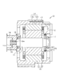
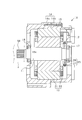
- FIG. 1 is an axial sectional view of a rotating electrical machine according to an embodiment.
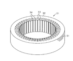
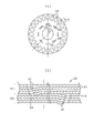
- FIG. 2 is a perspective view of the stator core
- FIG. 3 is a perspective view of the rotor core
- FIG. 4 is a diagram showing the configuration of the rotor core
- FIG. 5 is a diagram for explaining the configuration of each core block of the rotor core
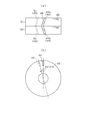
- FIG. 6 is a diagram for explaining the configuration of the boundary portion of each core block.
- FIG. 7 is a diagram for explaining the configuration of the steel plates at both axial ends in each core block
- FIG. 8 is a diagram showing keys provided on the rotor core
- FIG. 8 is a diagram showing keys provided on the rotor core
- FIG. 9 is a diagram illustrating an end-entanglement ring provided in the rotor core
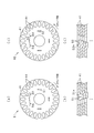
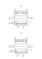
- FIG. 10 is a diagram illustrating a rotor core in which three or more core blocks are combined.
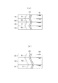
- FIG. 11 is a diagram for explaining the configuration of the steel plates at both axial ends in each core block;
- FIG. 12 is a diagram for explaining the configuration of the steel plates at both axial ends in each core block;
- FIG. 13 is a plan view of the intermediate steel plate,
- FIG. 14 is an axial cross-sectional view of a rotating electrical machine according to another example.
- the rotating electrical machine 10 is a squirrel-cage induction motor used as an AC generator for a vehicle.
- the rotating electrical machine 10 includes a rotor 12 (rotor) fixed to the rotating shaft 11, a stator 13 (stator) provided at a position surrounding the rotor 12, the rotor 12, And a housing 14 for housing the stator 13.
- the stator 13 has an annular shape, and has a stator core 21 that is arranged to face the outer periphery of the rotor 12 in the radial direction, and a stator winding 22 that is wound around the stator core 21.
- the housing 14 includes a pair of bottomed cylindrical housing members 14a and 14b, and is integrated by fastening bolts 15 in a state where the housing members 14a and 14b are joined at the openings.
- the housing 14 is provided with bearings 16 and 17, and the bearings 16 and 17 rotatably support the rotating shaft 11 and the rotor 12.
- a pulley 18 is attached to one end side of the rotating shaft 11. More specifically, a male screw portion 11 a is formed on one end side of the rotating shaft 11, and the male screw portion 11 a is inserted through a hole portion 18 a formed in the center portion of the pulley 18. And the pulley 18 is being fixed with respect to the rotating shaft 11 by fastening the nut 19 to the external thread part 11a.
- the pulley 18 may be fixed to the rotary shaft 11 by providing a female screw portion extending in the axial direction at the tip of the rotary shaft 11 and fastening a bolt to the female screw. That is, any configuration may be used as long as a fastening member that fixes the pulley 18 to the distal end portion of the rotating shaft 11 by an axial tightening force is attached.
- the rotary shaft 11 is provided with a resolver 25 as a rotation detector that detects the rotation of the rotor 12.
- the resolver 25 includes a resolver rotor 26 (detector rotor) fixed to the rotating shaft 11 and a resolver stator 27 (detector stator) that is annular and is disposed to face the outer periphery of the resolver rotor 26 in the radial direction. ing. More specifically, the resolver stator 27 has a resolver core and a resolver coil wound around the resolver core.
- the resolver rotor 26 rotates together with the rotating shaft 11, and the rotation speed of the rotating shaft 11 (rotor 12) is detected by a change in magnetic flux accompanying the rotation.
- a resolver rotor 26 may be fixed to the rotor 12.
- the stator core 21 constituting the stator 13 has the configuration shown in FIG. That is, the stator core 21 is an integral type formed by laminating a plurality of annular steel plates 31 in the axial direction of the stator core 21.
- the steel plate 31 is formed by press punching a strip-shaped electromagnetic steel plate material.
- the stator core 21 includes an annular back core portion 32 and a plurality of teeth 33 that protrude radially inward from the back core portion 32 and are arranged at a predetermined distance in the circumferential direction.
- a slot 34 (status lot) is formed between the two.
- slots 34 are provided at equal intervals in the circumferential direction, and the stator winding 22 is wound around the slots 34 (see FIG. 1).
- the number of slots 34 is 72. However, the number is arbitrary.
- These slots 34 are a U-phase slot, a V-phase slot, and a W-phase slot in the circumferential direction, respectively.
- the rotor core 40 constituting the rotor 12 will be described.
- the rotor core 40 is an integral type formed by laminating a plurality of annular steel plates 41 in the axial direction of the rotor core 40.
- the steel plate 41 is formed by press punching a strip-shaped electromagnetic steel plate material.
- the rotor core 40 is formed with a shaft hole 42 through which the rotating shaft 11 is inserted in the central portion in the radial direction.
- a plurality of slots 44 are formed at equal intervals in the circumferential direction, and a plurality of stacked holding portions 45 are formed at equal intervals in the circumferential direction.
- the slot 44 is provided on the outer edge portion of the core, and the stacked holding portion 45 is provided on the inner side thereof.
- the slot 44 is provided so as to penetrate in the axial direction of the rotor core 40, and the conductor bar 46 is filled in the slot 44 (see FIG. 4A).
- the number of slots 44 is 60. However, the number is arbitrary.
- the lamination holding portion 45 is a portion for holding a plurality of steel plates 41 in a laminated state. Specifically, the steel plates 41 are laminated by engagement (press fitting) of crimping portions provided on the steel plates 41. Held in a state.
- the number of stacked holding portions 45 is four. However, the number is arbitrary. Details will be described later.
- the rotor core 40 of the present embodiment is configured by laminating a plurality of steel plates 41 in a circumferentially skewed state at a predetermined angle, and in particular, includes two core blocks whose skew directions in the circumferential direction are opposite to each other. It is composed by combining. That is, as shown in FIG. 3, the rotor core 40 includes a first core block B1 and a second core block B2, and these are configured by being coupled in the axial direction. Therefore, as shown in FIG. 4A, the slot 44 is bent at a predetermined skew angle when viewed in the axial direction of the rotor core 40, and the conductor bar 46 is formed in the bent shape.
- FIG. 4A shows only one conductor bar 46 for convenience.
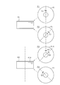
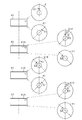
- FIG. 5A and 5B are diagrams showing the configuration of the first core block B1
- FIG. 5A is a plan view of the first core block B1
- FIG. 5B is a cross-sectional view taken along the line 5b-5b in FIG.
- FIGS. 5C and 5D are diagrams showing the configuration of the second core block B2
- FIG. 5C is a plan view of the second core block B2
- FIG. 5D is a sectional view taken along the line 5d-5d in FIG. is there.
- the number of slots 44 is reduced.
- Each of the caulking portions 51 is provided in a straight line so as to extend in a tangential direction of the circle on a circle centered on the core axis.
- the caulking portion 51 is formed in a cantilever shape by punching, and protrudes to one surface side in a state where only one side of the four sides of the rectangle, that is, one end portion of both ends in the circumferential direction is connected.
- the caulking base end portion 51a is inclined with respect to the steel plate surface, and the steel plate 41 is laminated so that a skew of a predetermined angle is given to each steel plate 41 by the caulking base end portion 51a.
- the first core block B1 is configured by laminating a plurality of steel plates 41 in a state where the plurality of steel plates 41 are engaged by the caulking portion 51 and skewed in the clockwise direction (first direction) in the figure in the circumferential direction.
- Each of the caulking portions 52 is provided in a straight line so as to extend in a tangential direction of the circle on a circle centered on the core axis.
- the crimping portion 52 is formed in a cantilever shape by punching, and protrudes to one surface side in a state where only one side of the four sides of the rectangle, that is, one end portion of both ends in the circumferential direction is connected.
- the caulking base end portion 52a is inclined obliquely with respect to the steel plate surface, and the steel plate 41 is laminated so that a predetermined angle skew is applied to each steel plate 41 by the caulking base end portion 52a.
- the second core block B2 is in a state in which the plurality of steel plates 41 are engaged by the crimping portion 52 and skewed in the counterclockwise direction of the drawing (second direction opposite to the first direction) in the circumferential direction. It is configured by stacking.
- the caulking portion 51 of the first core block B1 and the caulking portion 52 of the second core block B2 are formed in opposite directions and the same size, and are provided on circles having the same radius.
- the caulking part 51 corresponds to a “first caulking part”
- the caulking part 52 corresponds to a “second caulking part”.
- the caulking portion of the steel plate 41 at the axial end portion of the first core block B1 (the caulking portion at the end portion on the caulking protrusion side) is the second core block.
- a hole for inserting the caulking portion 51 of the first core block B1 is provided in the intermediate steel plate 41A, which is a steel plate at the block boundary position coupled to the first core block B1 in the second core block B2.
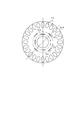
- FIG. 6 (a) shows the intermediate steel plate 41A
- FIG. 6 (b) shows a cross section at the joint portion of each of the core blocks B1 and B2, that is, a cross section of a portion including the intermediate steel plate 41A.
- the intermediate steel plate 41 ⁇ / b> A has four crimping portions 52 in the circumferential direction and four hole portions 53 in the circumferential direction.
- the caulking portions 52 and the holes 53 are alternately arranged in the circumferential direction on the same circle, and the intervals between the adjacent caulking portions 52 and the holes 53 are equal.
- the hole 53 is a punched hole formed by punching, for example, and has the same width and length as the crimped portions 51 and 52. However, the length may be longer than the caulking portions 51 and 52. Since the hole 53 has the same width as the caulking part 51 of the first core block B1, the caulking part 51 can be press-fitted, and it can be said that it is a caulking hole in that sense.
- the position of the hole 53 with respect to the caulking portion 52 is a position rotated by an angle ⁇ 1 in the circumferential direction.
- the caulking portion 51 of the first core block B1 enters the hole 53 of the intermediate steel plate 41A, and interference of the caulking portion 51 is avoided by the hole 53.
- the caulking portion 51 is inserted into the hole portion 53, the two steel plates 41 at the block boundary position can be caulked, and both the core blocks B1 and B2 are preferably used when the rotor core 40 is manufactured. Can be integrated.
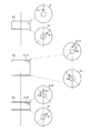
- the steel plates 41 at both axial ends in each of the core blocks B1 and B2 will be described with reference to FIG.
- the end steel plate at the upper end of the first core block B1 (opposite side of the second core block B2) is P1
- the end of the lower end (second core block B2 side) is indicated as P2
- the end steel plate at the upper end (first core block B1 side) of the second core block B2 is indicated as P3
- the end steel plate at the lower end (opposite side of the first core block B1) is indicated as P4.
- the slot 44 is not shown in each steel plate 41, and only one crimping portion 51, 52 is shown.
- the caulking positions of P2 to P4 and the like will be described with reference to the position of the caulking portion 51 indicated by P1.
- each steel plate 41 is skewed 45 ° in the clockwise direction in the figure from the upper steel plate 41 to the lower steel plate 41. Then, the position of the caulking portion 51 of the steel plate 41 at the lower end of the first core block B1 and the position of the hole 53 of the steel plate 41 (intermediate steel plate 41A) at the upper end of the second core block B2 are matched. 1 core block B1 and 2nd core block B2 are couple
- the position in the circumferential direction of the caulking portion 52 in the steel plate 41A is the same.
- the second core block B2 is a position rotated at an angle of 45 ° (that is, 360 ° / n / 2: n is the number of crimps) with respect to the crimped portion 51 in the steel plate 41 at the upper end of the first core block B1.
- the caulking part 51 is coupled to the first core block B1 by being inserted into the hole part 53.
- the first core block B1 is provided with a first rotor slot 44a penetrating in the stacking direction of the steel plates 41 and skewed at the same angle as the caulking portion 51
- the second core block B2 Is provided with a second rotor slot 44b penetrating in the stacking direction of the steel plates 41 and skewed to the opposite side of the first rotor slot 44a at the same angle as the caulking portion 52.
- the rotor slots 44a and 44b are connected to each other, and a conductor bar 46 is provided in the rotor slots 44a and 44b.
- the solid line indicates the slot position at the upper end of the first core block B1
- the broken line indicates the slot position at the lower end of the first core block B1.
- the slot 44 of the rotor core 40 may be skewed according to the number (m) of the slots 34 of the stator core 21.
- the shaft hole 42 formed at the center in the radial direction of the rotor core 40 is provided with a key 55 as a key structure.
- the key 55 is provided on at least one end side of both ends of the core so as to protrude toward the center of the shaft at the inner peripheral portion of the shaft hole 42.
- the key 55 is key-coupled to a key groove provided on the rotary shaft 11. Note that a key groove may be provided as a key structure portion instead of the key 55. Further, the key 55 (key structure portion) may be provided over the entire axial direction of the shaft hole 42.
- the end core ring 56 is provided by casting molten metal at both ends of the rotor core 40 in the axial direction, and each end portion of the stacked holding portion 45 is crimped by the end ring 56. 51 and 52 are covered. Further, the laminated holding part 45 is filled with the casting material from the crimping parts 51 and 52 located at both ends of the rotor core 40 to the crimping parts 51 and 52 of each laminated steel plate 41. . It is also possible to use a conductive non-metallic material as the casting material.
- the end ring 56 is caulked with respect to the height from the end face of the rotor core 40 in the portion covering the end of the conductor bar 46. It is preferable that the height of the portion covering the portions 51 and 52 is low.
- the hole 53 for inserting the caulking portion 51 of the first core block B1 is provided in the intermediate steel plate 41A that is the steel plate at the block boundary position coupled to the first core block B1 in the second core block B2. Therefore, interference with the caulking portion 51 can be avoided by the hole portion 53. Further, the caulking portion 51 of the first core block B1 is inserted into the hole 53 of the second core block B2, thereby facilitating mutual positioning of both the core blocks B1 and B2. As a result, the workability when manufacturing the rotor 12 can be improved.
- the core blocks B1 and B2 are integrally coupled in a press mold for press-working the steel plate 41, and then the cast portion is formed by a mold. In this step, work efficiency can be improved. In addition, the positional accuracy of the core blocks can be increased when the core blocks B1 and B2 are joined. Therefore, it is possible to suppress the inconvenience that the conductor bar 46 is locally thinned at the boundary between the core blocks B1 and B2.
- the positioning accuracy of the straight holes is determined by inserting a plurality of positioning pins throughout the entire axial direction. Considering the above, there is a concern that the hole positions vary, and as a result, the conductor bar is locally thinned. In this respect, the rotating electric machine 10 of the present embodiment can suppress the disadvantages as in the conventional technique.
- a caulking portion 51 is provided skewed from one axial end side of the first core block B1 (opposite side of the second core block B2) to the other axial end side (second core block B2 side), and the rotational angle in the circumferential direction Is “360 ° / n / 2” (n is the number of crimps).
- the circumferential direction position of the crimping part 51 in the steel plate 41 on the opposite side to the intermediate steel plate 41A among the steel plates 41 at both ends of the first core block B1 is the same as the circumferential position of the crimping part 52 in the intermediate steel plate 41A. ing.
- the caulking portions 51 and 52 can be evenly arranged in the entire circumferential direction across the first core block B1 and the second core block B2. Therefore, the thickness deviation in the circumferential direction can be reduced.
- the hole 53 provided in the intermediate steel plate 41A of the second core block B2 is a caulking hole that allows the caulking part 51 of the first core block B1 to be press-fitted. Therefore, the core blocks B1 and B2 can be coupled by caulking. Thereby, the workability
- the phase determination of the rotor core with respect to the rotating shaft 11 can be performed appropriately.
- Slots 44 (first rotor slot and second rotor slot) are provided at skew angles opposite to each other in each of the core blocks B1 and B2 of the rotor core 40, and a conductor bar is provided in the slot 44 in a state where these slots 44 are connected. 46 was provided. In this case, since the skew angle of the slot 44 is opposite in each of the core blocks B1 and B2, it is possible to generate forces in the opposite directions in each of the core blocks B1 and B2 when energizing the conductor bar 46 in the slot 44. The vibration in the axial direction can be suppressed.
- crimping portions 51 and 52 are provided at positions radially inward from the slots 44, respectively.
- crimped parts 51 and 52 can be provided suitably using the part which becomes a radial direction reverse side with respect to the stator 13 (stator).
- k slots 44 are provided at equal intervals in the circumferential direction, and each slot 44 is provided circumferentially between both axial ends of the core blocks B1 and B2.
- the skew was provided in a range of 360 ° / k. In this case, the radial excitation force caused by the slot 44 of the rotor core 40 can be reduced. In addition, magnetic noise can be reduced.
- m slots 34 are provided in the stator core 21 at equal intervals in the circumferential direction, and the slots 44 of the core blocks B1 and B2 are circumferentially arranged between both axial ends of the core blocks B1 and B2. Are skewed in a range of 360 ° / m. In this case, the radial excitation force caused by the slot 34 of the stator core 21 can be reduced. In addition, magnetic noise can be reduced.
- an end ring 56 is provided by casting at both ends of the rotor core 40 in the axial direction, and the end rings 56 cover the caulking portions 51 and 52 at both ends of the rotor core 40. did.
- the gap between the caulking portions 51 and 52 is filled with the casting material (molten metal) that forms the end ring 56, even if vibration or the like occurs during use of the rotating electrical machine 10, for example, the caulking of the laminated steel plate resulting therefrom Detachment can be suppressed.
- the height of the portion covering the crimping portions 51 and 52 is lower than the height from the end surface of the rotor core 40 in the portion covering the end portion of the conductor bar 46.
- casting material is allocated to each part according to the required amount in each part of the rotor 12, and the weight reduction and cost reduction in the rotor 12 can be achieved.
- the rotation detection may be affected by the axial displacement caused by vibration or the like.
- the rotor core 40 is combined with the core blocks B1 and B2 having different skew directions, it is possible to suppress the axial vibration, thereby suppressing the influence on the rotation detection, and thus the detection accuracy. Deterioration can be suppressed.
- the rotor core 40 may have a configuration in which three or more core blocks are coupled in the axial direction, for example, a configuration in which the first core block B1 is coupled to both sides in the axial direction of the second core block B2. To do.
- the configuration for example, the configurations shown in FIGS. 10A and 10B are assumed. In FIG. 10, for convenience, one stack holding part 45 (caulking part 51, 52) and one conductor bar 46 are shown.
- the first core block B1, the second core block B2, the first core block B1, and the second core block B2 are arranged in this order on the top and bottom of the drawing, and four core blocks are coupled. .
- the number of laminated steel plates 41 is the same.
- the first core block B1, the second core block B2, and the first core block B1 are arranged in this order on the top and bottom of the drawing, and the three core blocks are coupled.
- the number of stacked steel plates 41 is twice (the thickness is twice) the number of stacked first core blocks B1.
- FIG. 11 is a diagram for explaining the steel plate 41 of each of the core blocks B1 and B2 in the rotor core 40 of FIG. 10 (a).
- the illustration of the slot 44 in each steel plate 41 is omitted, and only one crimping portion 51, 52 is shown.
- the skew in each of the core blocks B1 and B2 is as described with reference to FIG.
- the upper steel sheet 41 is placed on the intermediate steel sheets 41A and 41B at the block boundary positions in the second, third, and fourth core blocks from the top.
- a hole 53 for inserting the crimped portion is provided.
- the intermediate steel plate 41B of the first core block B1 A hole 53 for inserting the caulking portion 52 of the two-core block B2 is formed.
- FIG. 12 is a view for explaining the steel plate 41 of each of the core blocks B1 and B2 in the rotor core 40 of FIG. 10 (b).
- the basic configuration is as described above. Since the core blocks are provided in three stages, in the second and third core blocks from the top, holes are formed in the intermediate steel plates 41A and 41B at the block boundary positions, respectively. A portion 53 is provided.
- the caulking portion 51 of the first core block B1 and the caulking portion 52 of the second core block B2 are provided on a circle having the same radius, but this is changed so that the caulking portions 51 and 52 are They may be provided on circles having different radii.
- the caulking part 51 of the first core block B1 is provided on the inner diameter side and the caulking part 52 of the second core block B2 is provided on the outer diameter side, as shown in FIG.
- the caulking portion 52 of the two-core block B2 is formed on the outer diameter side, and the hole portion 53 is formed on the inner diameter side.
- the protruding direction of the caulking portion in each of the core blocks B1 and B2 is the same in the axial direction, but this may be changed.
- the caulking portion may protrude toward the second core block B2 in the first core block B1
- the caulking portion may protrude toward the first core block B1 in the second core block B2.
- “holes” are preferably provided in the end steel plates (intermediate steel plates) of the core blocks B1 and B2 at the boundary portions of the core blocks B1 and B2.
- the caulking portions 51 and 52 provided on the steel plate 41 may be arcuate with a radius corresponding to the distance from the core axis instead of being linear.
- the hole 53 of the intermediate steel plate 41A is similarly arc-shaped. The hole 53 may be simply inserted instead of press-fitting the caulking portion.
- the pulley 18 is fixed to the tip of the rotating shaft 11 in the rotating electrical machine 10 (see FIG. 1), but this may be changed.
- the rotating electrical machine 10 shown in FIG. 14 in a configuration in which a rotating member Z (for example, a rotating shaft of a transmission) that rotates coaxially is connected to the tip of the rotating shaft 11, the rotating member is connected to the tip of the rotating shaft 11.
- a spline 58 is formed which is coupled to Z so as to be able to transmit power.
- the axial vibrations can be suppressed by combining the core blocks B1 and B2 having different skew directions in the rotor core 40, the wear of the spline 58 and foreign matter due to the axial vibrations can be suppressed. Generation can be suppressed.
- the rotary electric machine 10 can be put into practical use as a generator, an electric motor mounted on a vehicle, or those capable of exhibiting the functions of both. Moreover, it is also possible to use the rotary electric machine 10 of the said structure for uses other than vehicle mounting.
Abstract
La présente invention concerne un rotor (12) pour une machine dynamoélectrique (10) qui comprend : un premier bloc de noyau (B1) formé par empilement d'une pluralité de plaques d'acier annulaires (41) pendant que les plaques d'acier annulaires (41) sont mises en prise par des premières sections d'agrafage (51) et sont inclinées dans une première direction circonférentielle ; et un second bloc de noyau (B2) formé par empilement de plaques d'acier pendant que les plaques d'acier sont mises en prise par des secondes sections d'agrafage (52) et sont inclinées dans une seconde direction opposée à la première direction. Dans un noyau de rotor, le premier bloc de noyau et le second bloc de noyau sont joints axialement. Dans le second bloc de noyau, des trous (53) permettant d'y insérer les premières sections d'agrafage sont ménagés dans une plaque d'acier intermédiaire (41A) qui est la plaque d'acier se trouvant à la limite entre les blocs et qui est jointe au premier bloc de noyau.
Priority Applications (2)
| Application Number | Priority Date | Filing Date | Title |
|---|---|---|---|
| CN201780078788.XA CN110089005A (zh) | 2016-12-20 | 2017-11-22 | 旋转电机的转子和旋转电机 |
| US16/447,435 US11159066B2 (en) | 2016-12-20 | 2019-06-20 | Rotary electric machine and rotor mounted therein |
Applications Claiming Priority (2)
| Application Number | Priority Date | Filing Date | Title |
|---|---|---|---|
| JP2016-246540 | 2016-12-20 | ||
| JP2016246540A JP6665770B2 (ja) | 2016-12-20 | 2016-12-20 | 回転電機の回転子、及び回転電機 |
Related Child Applications (1)
| Application Number | Title | Priority Date | Filing Date |
|---|---|---|---|
| US16/447,435 Continuation US11159066B2 (en) | 2016-12-20 | 2019-06-20 | Rotary electric machine and rotor mounted therein |
Publications (1)
| Publication Number | Publication Date |
|---|---|
| WO2018116738A1 true WO2018116738A1 (fr) | 2018-06-28 |
Family
ID=62627333
Family Applications (1)
| Application Number | Title | Priority Date | Filing Date |
|---|---|---|---|
| PCT/JP2017/042110 WO2018116738A1 (fr) | 2016-12-20 | 2017-11-22 | Rotor pour machine dynamoélectrique et machine dynamoélectrique |
Country Status (4)
| Country | Link |
|---|---|
| US (1) | US11159066B2 (fr) |
| JP (1) | JP6665770B2 (fr) |
| CN (1) | CN110089005A (fr) |
| WO (1) | WO2018116738A1 (fr) |
Families Citing this family (5)
| Publication number | Priority date | Publication date | Assignee | Title |
|---|---|---|---|---|
| JP6848029B1 (ja) * | 2019-10-08 | 2021-03-24 | 株式会社東芝 | 回転電機の回転子 |
| CN111817462B (zh) * | 2020-06-12 | 2021-11-30 | 卓尔博(宁波)精密机电股份有限公司 | 一种大回转扭斜圆扣自铆转子及转子压铆模具 |
| US11245318B1 (en) * | 2020-07-29 | 2022-02-08 | Schaeffler Technologies AG & Co. KG | Resolver clamping plate for electric motor |
| CN116260260A (zh) * | 2021-12-10 | 2023-06-13 | 安徽威灵汽车部件有限公司 | 电机、电动助力转向系统和车辆 |
| CN113991900B (zh) * | 2021-12-23 | 2022-03-22 | 宁波震裕科技股份有限公司 | 一种周向大扭矩斜槽铁芯的叠铆结构及该铁芯的制造工艺 |
Citations (14)
| Publication number | Priority date | Publication date | Assignee | Title |
|---|---|---|---|---|
| JPS57155980U (fr) * | 1981-03-25 | 1982-09-30 | ||
| JPS58116033A (ja) * | 1981-12-29 | 1983-07-11 | Kuroda Precision Ind Ltd | 積層鉄心およびその金型装置 |
| JPS5937879U (ja) * | 1982-08-31 | 1984-03-09 | 三菱電機株式会社 | 回転電機 |
| JPH0421172U (fr) * | 1990-06-11 | 1992-02-21 | ||
| JPH08294242A (ja) * | 1995-04-20 | 1996-11-05 | Shinko Electric Co Ltd | 回転電機のロータコアまたはステータコアのスキュー |
| JPH10225034A (ja) * | 1997-02-12 | 1998-08-21 | Hitachi Ltd | 回転電機の回転子 |
| JPH1141872A (ja) * | 1997-07-15 | 1999-02-12 | Hitachi Ltd | 電動機の回転子 |
| JP2002136015A (ja) * | 2000-10-24 | 2002-05-10 | Mitsubishi Heavy Ind Ltd | 電動機 |
| JP2004064799A (ja) * | 2002-06-03 | 2004-02-26 | Akira Wakaguwa | 鉄心の成形方法および電動機の製造方法 |
| JP2004153962A (ja) * | 2002-10-31 | 2004-05-27 | Yaskawa Electric Corp | Vカシメ付き電磁鋼板およびその回転子 |
| JP2009278783A (ja) * | 2008-05-15 | 2009-11-26 | Toshiba Industrial Products Manufacturing Corp | かご型回転子 |
| JP2011244594A (ja) * | 2010-05-18 | 2011-12-01 | Sinfonia Technology Co Ltd | かご形回転子、かご形回転子の製造方法 |
| JP2012210075A (ja) * | 2011-03-30 | 2012-10-25 | Panasonic Corp | モータおよびポンプならびにポンプ駆動機器 |
| WO2015125254A1 (fr) * | 2014-02-20 | 2015-08-27 | 三菱電機株式会社 | Rotor, moteur électrique à aimants permanents équipé dudit rotor, machine à fluides équipée d'un moteur électrique à aimants permanents et procédé de fabrication de rotor |
Family Cites Families (13)
| Publication number | Priority date | Publication date | Assignee | Title |
|---|---|---|---|---|
| JP2756899B2 (ja) * | 1993-02-19 | 1998-05-25 | 株式会社三井ハイテック | 積層鉄心の製造方法 |
| US5758709A (en) * | 1995-12-04 | 1998-06-02 | General Electric Company | Method of fabricating a rotor for an electric motor |
| CN100536288C (zh) * | 1999-07-16 | 2009-09-02 | 松下电器产业株式会社 | 永久磁铁同步电动机 |
| JP3687749B2 (ja) * | 2003-04-23 | 2005-08-24 | 株式会社三井ハイテック | スキュー形状可変型積層鉄心及びその製造方法 |
| JP2008178229A (ja) * | 2007-01-19 | 2008-07-31 | Nippon Densan Corp | モータ |
| US8120226B2 (en) * | 2008-10-24 | 2012-02-21 | GM Global Technology Operations LLC | Methods and apparatus for an electric machine with a cast rotor |
| CN102640397A (zh) * | 2009-12-24 | 2012-08-15 | 株式会社安川电机 | 层压铁心、具备该层压铁心的电动机及层压铁心的制造方法 |
| US8424188B2 (en) * | 2011-02-23 | 2013-04-23 | GM Global Technology Operations LLC | Method of manufacturing an end ring over pre-formed conductor bars of a rotor for an electric device |
| JP5893904B2 (ja) * | 2011-11-30 | 2016-03-23 | 東芝産業機器システム株式会社 | 積層鉄心及びその製造方法 |
| US9013086B2 (en) * | 2012-03-23 | 2015-04-21 | Whirlpool Corporation | Stator for an electric motor including separately formed end pieces and associated method |
| JP5873420B2 (ja) * | 2012-11-30 | 2016-03-01 | 三菱電機株式会社 | ロータコアの製造方法 |
| US20140246943A1 (en) * | 2013-03-01 | 2014-09-04 | GM Global Technology Operations LLC | Optimum rotor skew angle for an electric machine |
| KR101878677B1 (ko) * | 2017-06-29 | 2018-07-16 | 엘지전자 주식회사 | 전동기의 로터 |
-
2016
- 2016-12-20 JP JP2016246540A patent/JP6665770B2/ja active Active
-
2017
- 2017-11-22 WO PCT/JP2017/042110 patent/WO2018116738A1/fr active Application Filing
- 2017-11-22 CN CN201780078788.XA patent/CN110089005A/zh not_active Withdrawn
-
2019
- 2019-06-20 US US16/447,435 patent/US11159066B2/en active Active
Patent Citations (14)
| Publication number | Priority date | Publication date | Assignee | Title |
|---|---|---|---|---|
| JPS57155980U (fr) * | 1981-03-25 | 1982-09-30 | ||
| JPS58116033A (ja) * | 1981-12-29 | 1983-07-11 | Kuroda Precision Ind Ltd | 積層鉄心およびその金型装置 |
| JPS5937879U (ja) * | 1982-08-31 | 1984-03-09 | 三菱電機株式会社 | 回転電機 |
| JPH0421172U (fr) * | 1990-06-11 | 1992-02-21 | ||
| JPH08294242A (ja) * | 1995-04-20 | 1996-11-05 | Shinko Electric Co Ltd | 回転電機のロータコアまたはステータコアのスキュー |
| JPH10225034A (ja) * | 1997-02-12 | 1998-08-21 | Hitachi Ltd | 回転電機の回転子 |
| JPH1141872A (ja) * | 1997-07-15 | 1999-02-12 | Hitachi Ltd | 電動機の回転子 |
| JP2002136015A (ja) * | 2000-10-24 | 2002-05-10 | Mitsubishi Heavy Ind Ltd | 電動機 |
| JP2004064799A (ja) * | 2002-06-03 | 2004-02-26 | Akira Wakaguwa | 鉄心の成形方法および電動機の製造方法 |
| JP2004153962A (ja) * | 2002-10-31 | 2004-05-27 | Yaskawa Electric Corp | Vカシメ付き電磁鋼板およびその回転子 |
| JP2009278783A (ja) * | 2008-05-15 | 2009-11-26 | Toshiba Industrial Products Manufacturing Corp | かご型回転子 |
| JP2011244594A (ja) * | 2010-05-18 | 2011-12-01 | Sinfonia Technology Co Ltd | かご形回転子、かご形回転子の製造方法 |
| JP2012210075A (ja) * | 2011-03-30 | 2012-10-25 | Panasonic Corp | モータおよびポンプならびにポンプ駆動機器 |
| WO2015125254A1 (fr) * | 2014-02-20 | 2015-08-27 | 三菱電機株式会社 | Rotor, moteur électrique à aimants permanents équipé dudit rotor, machine à fluides équipée d'un moteur électrique à aimants permanents et procédé de fabrication de rotor |
Also Published As
| Publication number | Publication date |
|---|---|
| JP2018102049A (ja) | 2018-06-28 |
| CN110089005A (zh) | 2019-08-02 |
| US11159066B2 (en) | 2021-10-26 |
| JP6665770B2 (ja) | 2020-03-13 |
| US20190312473A1 (en) | 2019-10-10 |
Similar Documents
| Publication | Publication Date | Title |
|---|---|---|
| WO2018116738A1 (fr) | Rotor pour machine dynamoélectrique et machine dynamoélectrique | |
| JP4863061B2 (ja) | 電動モータ | |
| JP5418837B2 (ja) | 積層巻きコア及びこれを備えた回転子、回転電機 | |
| US20130285500A1 (en) | Rotor for a motor and a motor | |
| JP2010220288A (ja) | コアブロック及び該コアブロックを用いたモータ用の磁極コア | |
| JP6044382B2 (ja) | マルチギャップ型回転電機 | |
| JP6026021B2 (ja) | 磁気誘導子型電動機およびその製造方法 | |
| JP2010068569A (ja) | ステータ | |
| JPWO2017141361A1 (ja) | 回転電機及び回転電機の製造方法 | |
| WO2017195498A1 (fr) | Rotor et machine électrique rotative | |
| CN112119572B (zh) | 旋转电机的转子以及旋转电机的转子芯支承构造 | |
| JP2017093059A (ja) | 回転電機 | |
| WO2017159811A1 (fr) | Machine dynamo-électrique et procédé de fabrication de machine dynamo-électrique | |
| JP5306309B2 (ja) | 外転型の電動機 | |
| JP2014087092A (ja) | 回転子およびそれを用いた回転電機 | |
| JP6136477B2 (ja) | 回転電機およびその製造方法 | |
| JP6297802B2 (ja) | レゾルバの取り付け構造 | |
| WO2019189313A1 (fr) | Rotor, moteur, et dispositif de direction assistée électrique | |
| JP4386909B2 (ja) | モータ | |
| JP2005269831A (ja) | ブラシレスdcモータ | |
| US9106116B2 (en) | Rotor of rotating electrical machine | |
| JP5314115B2 (ja) | レゾルバ | |
| WO2019044206A1 (fr) | Machine dynamo-électrique | |
| CN111630752B (zh) | 旋转电机的定子和旋转电机的定子的制造方法 | |
| JP5256835B2 (ja) | 回転電機の固定子及び回転電機 |
Legal Events
| Date | Code | Title | Description |
|---|---|---|---|
| 121 | Ep: the epo has been informed by wipo that ep was designated in this application |
Ref document number: 17884588 Country of ref document: EP Kind code of ref document: A1 |
|
| NENP | Non-entry into the national phase |
Ref country code: DE |
|
| 122 | Ep: pct application non-entry in european phase |
Ref document number: 17884588 Country of ref document: EP Kind code of ref document: A1 |