WO2018105472A1 - 炭素触媒並びにこれを含む電極及び電池 - Google Patents
炭素触媒並びにこれを含む電極及び電池 Download PDFInfo
- Publication number
- WO2018105472A1 WO2018105472A1 PCT/JP2017/042951 JP2017042951W WO2018105472A1 WO 2018105472 A1 WO2018105472 A1 WO 2018105472A1 JP 2017042951 W JP2017042951 W JP 2017042951W WO 2018105472 A1 WO2018105472 A1 WO 2018105472A1
- Authority
- WO
- WIPO (PCT)
- Prior art keywords
- peak
- catalyst
- carbon
- electrode
- range
- Prior art date
- Legal status (The legal status is an assumption and is not a legal conclusion. Google has not performed a legal analysis and makes no representation as to the accuracy of the status listed.)
- Ceased
Links
Images


Classifications
-
- H—ELECTRICITY
- H01—ELECTRIC ELEMENTS
- H01M—PROCESSES OR MEANS, e.g. BATTERIES, FOR THE DIRECT CONVERSION OF CHEMICAL ENERGY INTO ELECTRICAL ENERGY
- H01M4/00—Electrodes
- H01M4/86—Inert electrodes with catalytic activity, e.g. for fuel cells
- H01M4/96—Carbon-based electrodes
-
- H—ELECTRICITY
- H01—ELECTRIC ELEMENTS
- H01M—PROCESSES OR MEANS, e.g. BATTERIES, FOR THE DIRECT CONVERSION OF CHEMICAL ENERGY INTO ELECTRICAL ENERGY
- H01M4/00—Electrodes
- H01M4/86—Inert electrodes with catalytic activity, e.g. for fuel cells
- H01M4/90—Selection of catalytic material
-
- B—PERFORMING OPERATIONS; TRANSPORTING
- B01—PHYSICAL OR CHEMICAL PROCESSES OR APPARATUS IN GENERAL
- B01J—CHEMICAL OR PHYSICAL PROCESSES, e.g. CATALYSIS OR COLLOID CHEMISTRY; THEIR RELEVANT APPARATUS
- B01J21/00—Catalysts comprising the elements, oxides, or hydroxides of magnesium, boron, aluminium, carbon, silicon, titanium, zirconium, or hafnium
- B01J21/18—Carbon
-
- B—PERFORMING OPERATIONS; TRANSPORTING
- B01—PHYSICAL OR CHEMICAL PROCESSES OR APPARATUS IN GENERAL
- B01J—CHEMICAL OR PHYSICAL PROCESSES, e.g. CATALYSIS OR COLLOID CHEMISTRY; THEIR RELEVANT APPARATUS
- B01J27/00—Catalysts comprising the elements or compounds of halogens, sulfur, selenium, tellurium, phosphorus or nitrogen; Catalysts comprising carbon compounds
- B01J27/14—Phosphorus; Compounds thereof
- B01J27/185—Phosphorus; Compounds thereof with iron group metals or platinum group metals
- B01J27/1853—Phosphorus; Compounds thereof with iron group metals or platinum group metals with iron, cobalt or nickel
-
- H—ELECTRICITY
- H01—ELECTRIC ELEMENTS
- H01M—PROCESSES OR MEANS, e.g. BATTERIES, FOR THE DIRECT CONVERSION OF CHEMICAL ENERGY INTO ELECTRICAL ENERGY
- H01M4/00—Electrodes
- H01M4/86—Inert electrodes with catalytic activity, e.g. for fuel cells
- H01M4/8647—Inert electrodes with catalytic activity, e.g. for fuel cells consisting of more than one material, e.g. consisting of composites
- H01M4/8652—Inert electrodes with catalytic activity, e.g. for fuel cells consisting of more than one material, e.g. consisting of composites as mixture
-
- H—ELECTRICITY
- H01—ELECTRIC ELEMENTS
- H01M—PROCESSES OR MEANS, e.g. BATTERIES, FOR THE DIRECT CONVERSION OF CHEMICAL ENERGY INTO ELECTRICAL ENERGY
- H01M4/00—Electrodes
- H01M4/86—Inert electrodes with catalytic activity, e.g. for fuel cells
- H01M4/90—Selection of catalytic material
- H01M4/9008—Organic or organo-metallic compounds
-
- H—ELECTRICITY
- H01—ELECTRIC ELEMENTS
- H01M—PROCESSES OR MEANS, e.g. BATTERIES, FOR THE DIRECT CONVERSION OF CHEMICAL ENERGY INTO ELECTRICAL ENERGY
- H01M4/00—Electrodes
- H01M4/86—Inert electrodes with catalytic activity, e.g. for fuel cells
- H01M4/90—Selection of catalytic material
- H01M4/9041—Metals or alloys
-
- B—PERFORMING OPERATIONS; TRANSPORTING
- B01—PHYSICAL OR CHEMICAL PROCESSES OR APPARATUS IN GENERAL
- B01J—CHEMICAL OR PHYSICAL PROCESSES, e.g. CATALYSIS OR COLLOID CHEMISTRY; THEIR RELEVANT APPARATUS
- B01J31/00—Catalysts comprising hydrides, coordination complexes or organic compounds
- B01J31/02—Catalysts comprising hydrides, coordination complexes or organic compounds containing organic compounds or metal hydrides
- B01J31/0234—Nitrogen-, phosphorus-, arsenic- or antimony-containing compounds
- B01J31/0255—Phosphorus containing compounds
- B01J31/0257—Phosphorus acids or phosphorus acid esters
-
- H—ELECTRICITY
- H01—ELECTRIC ELEMENTS
- H01M—PROCESSES OR MEANS, e.g. BATTERIES, FOR THE DIRECT CONVERSION OF CHEMICAL ENERGY INTO ELECTRICAL ENERGY
- H01M12/00—Hybrid cells; Manufacture thereof
- H01M12/04—Hybrid cells; Manufacture thereof composed of a half-cell of the fuel-cell type and of a half-cell of the primary-cell type
- H01M12/06—Hybrid cells; Manufacture thereof composed of a half-cell of the fuel-cell type and of a half-cell of the primary-cell type with one metallic and one gaseous electrode
-
- H—ELECTRICITY
- H01—ELECTRIC ELEMENTS
- H01M—PROCESSES OR MEANS, e.g. BATTERIES, FOR THE DIRECT CONVERSION OF CHEMICAL ENERGY INTO ELECTRICAL ENERGY
- H01M12/00—Hybrid cells; Manufacture thereof
- H01M12/08—Hybrid cells; Manufacture thereof composed of a half-cell of a fuel-cell type and a half-cell of the secondary-cell type
Definitions
- the present invention relates to a carbon catalyst, and an electrode and a battery including the carbon catalyst.
- Patent Document 1 discloses an oxygen reduction catalyst comprising a graphene skeleton containing a laminate of single-layer graphene and a phosphorus compound, wherein a part of carbon atoms of the graphene is substituted with a nitrogen atom, and an X-ray photoelectron
- the peak of the phosphorus 2p orbital is 133.0 to 134.5 eV, or in the X-ray photoelectron spectrum, the peak of the phosphorus 2p orbital is 1. on the higher energy side than the peak of the phosphorus 2p orbital of tetra n-butylphosphonium bromide.
- An oxygen reduction catalyst that is shifted by 0 to 2.5 eV is described, and it is also described that the oxygen reduction catalyst further contains iron or cobalt and further contains platinum.
- the present invention has been made in view of the above problems, and an object thereof is to provide a carbon catalyst having improved catalytic activity, and an electrode and a battery including the carbon catalyst.
- a carbon catalyst according to an embodiment of the present invention for solving the above-described problem is a carbon catalyst containing a metal and a phosphorus atom, and in an X-ray photoelectron spectroscopy measurement, phosphorous with respect to the concentration (atomic%) of carbon atoms.
- the ratio of the concentration (atomic%) of phosphorus atoms showing a peak having a peak top in the range of 132.5 ⁇ 0.3 eV and a full width at half maximum of 2.0 ⁇ 0.5 eV obtained by peak separation of the atomic P2p peak is , 0.0005 or more.
- a carbon catalyst having improved catalytic activity is provided.
- the carbon catalyst has an area of the following peak (2) with respect to the total area of the following five peaks (1) to (5) obtained by peak separation of the phosphorus atom P2p peak in the X-ray photoelectron spectroscopy measurement.
- (1) A peak having a peak top in the range of 130.0 ⁇ 0.3 eV and a full width at half maximum of 2.0 ⁇ 0.5 eV;
- (2) A peak having a peak top in the range of 132.5 ⁇ 0.3 eV and a full width at half maximum of 2.0 ⁇ 0.5 eV; (3) a full width at half maximum having a peak top in the range of 133.2 ⁇ 0.3 eV (4) a peak having a peak top in the range of 133.9 ⁇ 0.3 eV and a full width at half maximum of 2.0 ⁇ 0.5 eV; and (5) 135.
- Has a peak top in the range of 6 ⁇ 0.4eV Peak full width at half maximum is 2.0 ⁇ 0.5eV.
- the carbon catalyst has an area ratio of the following two peaks f broad and f narrow obtained by separating peaks having a diffraction angle (2 ⁇ ) in the X-ray diffraction pattern of around 26 ° ( %) May have a carbon structure satisfying the following conditions (a) and (b):
- the diffraction angle (2 ⁇ ) has a peak top in the range of 23.5 ° ⁇ 3.5 ° and a half value Peak f broad whose total width is 10.0 ° ⁇ 5.0 °: 73.0% or more and less than 100.0%;
- the diffraction angle (2 ⁇ ) is in the range of 26.5 ° ⁇ 1.0 °.
- peak f narrow full width at half maximum has a peak top is 3.5 ° ⁇ 3.0 °: 0.0% greater than 27.0% or less.
- An electrode according to an embodiment of the present invention for solving the above-described problems includes any one of the carbon catalysts described above. According to the present invention, an electrode with improved performance is provided.
- a battery according to an embodiment of the present invention for solving the above-described problems includes the electrode. According to the present invention, a battery with improved performance is provided.
- a carbon catalyst with improved catalytic activity and an electrode and a battery including the same are provided.
- the carbon catalyst according to the present embodiment is a carbon catalyst containing a metal and a phosphorus atom, and the concentration (atomic%) of carbon atoms in X-ray photoelectron spectroscopy (XPS) measurement.
- XPS X-ray photoelectron spectroscopy
- the present catalyst is a carbon catalyst containing metal and phosphorus atoms. More specifically, as will be described later, the present catalyst is a carbonized material containing a metal and a phosphorus atom obtained by carbonizing a raw material containing an organic substance, a metal, and a phosphorus compound.
- the metal contained in the catalyst is preferably a transition metal.
- the transition metal is a metal belonging to Group 3 to Group 12 of the periodic table, and one or more transition metals belonging to Group 4 to Group 12 of the periodic table are preferably used.
- the transition metal is, for example, scandium (Sc), titanium (Ti), vanadium (V), chromium (Cr), manganese (Mn), iron (Fe), cobalt (Co), nickel (Ni), Copper (Cu), zinc (Zn), yttrium (Y), zirconium (Zr), niobium (Nb), molybdenum (Mo), ruthenium (Ru), rhodium (Rh), palladium (Pd), lanthanoid (cerium (Ce) ) Etc.) and actinoids, and may be at least one selected from the group consisting of actinoids, preferably selected from the group consisting of Sc, Ti, V, Cr, Mn, Fe, Co, Ni, Cu and Zn. It is 1 or more types, and 1 or more types selected from the group which consists of Fe, Cu, and Zn may be sufficient.
- actinoids preferably selected from the group consisting of Sc, Ti, V, Cr, Mn, Fe, Co, Ni
- This catalyst has a peak top in the range of 132.5 ⁇ 0.3 eV with respect to the carbon atom concentration (atomic%) obtained by XPS measurement, and has a full width at half maximum.
- a specific phosphorus atom concentration (atomic%) ratio (P 132.5 / C ratio) showing a peak (peak P 132.5 ) of 2.0 ⁇ 0.5 eV is a predetermined threshold value or more. .
- the inventors of the present invention have made extensive studies on technical means for improving the catalytic activity of a carbon catalyst containing a metal and a phosphorus atom, and as a result, the peak obtained by peak separation of the phosphorus atom P2p peak in the XPS spectrum.
- the inventors have found that the specific phosphorus atom representing P 132.5 contributes to the improvement of the catalytic activity of the carbon catalyst, and have completed the present invention.
- a P2p peak appears in the range of 133 ⁇ 3.3 eV.
- the P2p peak includes peaks of five types of phosphorus atoms having different oxidation states due to different bonding methods with other atoms.
- the P2p peak can be separated into the following five peaks (1) to (5) by the peak separation described in detail in the examples below: (1) Range of 130.0 ⁇ 0.3 eV (Peak P 130.0 ); (2) full width at half maximum with a peak top in the range of 132.5 ⁇ 0.3 eV.
- the inventors of the present invention indicate that, among these five peaks, the phosphorus atom showing a specific peak called the peak P 132.5 contributes to the catalytic activity of the carbon catalyst containing the metal and the phosphorus atom. I found.
- this peak P 132.5 is specified as one of the five peaks obtained by peak separation of the phosphorus atom P2p peak in the XPS spectrum of the catalyst.
- the phosphorus atom showing the peak P 132.5 includes, for example, a phosphorus atom bonded to one or two oxygen atoms and also bonded to one or two carbon atoms. More specifically, the phosphorus atom having the peak P 132.5 is bonded to, for example, a phosphorus atom bonded to two oxygen atoms and bonded to two carbon atoms and / or two oxygen atoms. And a phosphorus atom bonded to one carbon atom.
- the peak P 130.0 is a peak derived from a single phosphorus atom.
- the peak P 133.2 is a peak derived from a phosphoric acid type phosphorus atom.
- the peak P 133.9 is a peak derived from the phosphorus atom of the —O—PO 3 atomic group.
- the peak P135.6 is a peak derived from a phosphorus atom of a phosphorus pentoxide type.
- the results of the P2p peak was a peak separation for separating the five peaks, sometimes at least one of the four peaks other than the peak P 132.5 is not substantially detected.
- the P 132.5 / C ratio of the present catalyst is not particularly limited as long as it is 0.0005 or more. However, for example, it is preferably 0.0010 or more, and more preferably 0.0020 or more. Further, when the P 132.5 / C ratio of the present catalyst is 0.0020 or more, the P 132.5 / C ratio is preferably 0.0040 or more, and more preferably 0.0045 or more. Preferably, it is more preferably 0.0050 or more, and particularly preferably 0.0055 or more.
- the upper limit value of the P 132.5 / C ratio of the present catalyst is not particularly limited, the P 132.5 / C ratio may be 0.45 or less, for example.
- This catalyst has an excellent catalytic activity when the P 132.5 / C ratio is in any of the above ranges.
- the present catalyst is obtained by the above-described five peaks (1) to (5) (peak P 130.0 , peak P 132.5 , peak P 133. 2 , the ratio of the area of the peak (2) (peak P 132.5 ) to the sum of the areas of the peak P 133.9 and the peak P 135.6 ) may be 0.3000 or more.
- the area of peak P 130.0 , the area of peak P 132.5 , the area of peak P 133.2 , the area of peak P 133.9 , and the peak obtained by XPS of the present catalyst To the sum of P 135.6 and the area (area P total ).
- the ratio (P 132.5 / P total ratio) of the area (area P 132.5 ) of the peak P 132.5 is 0.3000 or more.
- the area of the peak that has not been detected Is calculated as P 132.5 / P total .
- the ratio of the concentration of phosphorus atoms (atomic%) to the concentration of carbon atoms (atomic%) obtained by XPS of the present catalyst (hereinafter sometimes referred to as “P / C ratio”) is not particularly limited.
- P / C ratio The ratio of the concentration of phosphorus atoms (atomic%) to the concentration of carbon atoms (atomic%) obtained by XPS of the present catalyst (hereinafter sometimes referred to as “P / C ratio”) is not particularly limited.
- it may be 0.0020 or more, preferably 0.0040 or more, more preferably 0.0085 or more, still more preferably 0.0090 or more, 0.0095 The above is particularly preferable.
- the upper limit value of the P / C ratio of the present catalyst is not particularly limited, but the P / C ratio may be 0.45 or less, for example.
- the concentration (atomic%) of phosphorus atoms obtained by XPS of the present catalyst is not particularly limited, but may be, for example, 0.20 atomic% or more, and preferably 0.40 atomic% or more. And more preferably 0.70 atomic% or more, and particularly preferably 0.75 atomic% or more.
- the upper limit of the phosphorus atom concentration (atomic%) of the catalyst is not particularly limited, but the phosphorus atom concentration (atomic%) may be, for example, 30 (atomic%) or less.
- the present catalyst has the following two peaks f broad and f narrow area ratio (%) obtained by separating peaks having a diffraction angle (2 ⁇ ) in the X-ray diffraction pattern of around 26 °.
- the carbon catalyst has a laminated structure composed of curved network surfaces that contribute to its catalytic activity, in its X-ray diffraction diagram, the diffraction angle (2 ⁇ ) is around 26 ° (23 ° or more, 27 °
- a diffraction peak of the carbon (002) plane appears in the following range).
- the peak, the graphite structure peak derived from the (002) plane of the graphite structure is a high-crystalline component (f narrow), it is mixed in two peaks with a peak derived from the low crystalline component (f broad) .
- the peak near 26 ° can be separated into two peaks f broad and f narrow by peak separation in the X-ray diffraction diagram. Specifically, this peak separation is performed by the following procedure. First, the X-ray diffraction pattern obtained by powder X-ray diffraction measurement is corrected for the intensity of the polarization factor, Lorentz factor, and carbon atom scattering factor, and has a diffraction angle of about 10 ° to 20 ° and a diffraction angle of 30 °. Background correction is performed by subtracting this straight line from each diffraction intensity after intensity correction, using a straight line connecting about ⁇ 40 ° as a background.
- the residual square means the square of the residual at each measured diffraction angle, and the residual sum of squares is the sum of these residual squares.
- the peak f broad has a peak top in a diffraction angle range of 23.5 ° ⁇ 3.5 °, and its full width at half maximum is 10.0 ° ⁇ 5.0 °.
- the peak fnarrow has a peak top in a diffraction angle range of 26.5 ° ⁇ 1.0 °, and its full width at half maximum is 3.5 ° ⁇ 3.0 °. Then, the diffraction angle of the peak f narrow is greater than the diffraction angle of the peak f broad.
- the above two peaks of the catalyst are represented by the following conditions (a) and (b): (a) fbroad : 90.0% or more and 99.9% or less; and (b) fnarrow : 0.1% It is good also as satisfy
- each range of the condition (b) is not limited to 0.1%.
- each range of the condition (b) is 0.2% or more, and each range of the condition (a) is 99%. It may be 8% or less.
- the carbon structure of the catalyst has a low crystalline component that satisfies the condition (a) and a high that satisfies the condition (b). Having a crystal component effectively contributes to the catalytic activity and / or durability of the present catalyst.
- This catalyst has catalytic activity. Specifically, this catalyst has, for example, oxygen reduction activity. In this case, the present catalyst effectively catalyzes an oxygen reduction reaction in, for example, a fuel cell electrode or an air cell electrode.
- the oxygen reduction activity of this catalyst is, for example, data showing the relationship between voltage and current density obtained by sweeping and applying a potential using a rotating ring disk electrode device having a working electrode coated with this catalyst (oxygen reduction voltammogram) , The current density i 0.5 (mA / cm 2 ) when a voltage of 0.5 V (vs. RHE) is applied.
- the current density i 0.5 exhibited by the present catalyst is, for example, ⁇ 1.0 (mA / cm 2 ) or less (for example, ⁇ 1.0 (mA / cm 2 ) to ⁇ 5.0 (mA / cm). 2 )) or less than ⁇ 1.5 (mA / cm 2 ) (for example, ⁇ 1.5 (mA / cm 2 ) to ⁇ 5.0 (mA / cm 2 )).
- -2.1 (mA / cm 2) or less e.g., -2.1 (mA / cm 2) ⁇ -5.0 (mA / cm 2)
- particularly preferably particularly preferably.
- This catalyst can be obtained by carbonizing a raw material containing an organic substance, a metal, and a phosphorus compound. That is, this catalyst is a carbonized material of a raw material containing an organic substance, a metal, and a phosphorus compound.
- the organic substance contained in the raw material is not particularly limited as long as it can be carbonized. That is, as the organic substance, for example, a high molecular weight organic compound (for example, a resin such as a thermosetting resin and / or a thermoplastic resin) and / or a low molecular weight organic compound is used. Moreover, it is good also as using biomass as organic substance.
- a nitrogen-containing organic substance is preferably used as the organic substance.
- the nitrogen-containing organic substance is not particularly limited as long as it is an organic substance containing an organic compound containing a nitrogen atom in its molecule, and any one or more kinds are used.
- the present catalyst obtained by using a raw material containing a nitrogen-containing organic substance contains a nitrogen atom.
- the content of the organic substance in the raw material is not particularly limited as long as the present catalyst is obtained.
- it may be 5% by mass or more and 90% by mass or less, and may be 10% by mass or more and 80% by mass or less. It is preferable that
- the metal contained in the raw material (that is, the metal contained in the catalyst) is preferably a transition metal.
- the transition metal is a metal belonging to Group 3 to Group 12 of the periodic table, and one or more transition metals belonging to Group 4 to Group 12 of the periodic table are preferably used.
- the transition metal is, for example, scandium (Sc), titanium (Ti), vanadium (V), chromium (Cr), manganese (Mn), iron (Fe), cobalt (Co), nickel (Ni), Copper (Cu), zinc (Zn), yttrium (Y), zirconium (Zr), niobium (Nb), molybdenum (Mo), ruthenium (Ru), rhodium (Rh), palladium (Pd), lanthanoid (cerium (Ce) ) Etc.) and actinoids, and may be at least one selected from the group consisting of actinoids, preferably selected from the group consisting of Sc, Ti, V, Cr, Mn, Fe, Co, Ni, Cu and Zn. It is 1 or more types, and 1 or more types selected from the group which consists of Fe, Cu, and Zn may be sufficient.
- actinoids preferably selected from the group consisting of Sc, Ti, V, Cr, Mn, Fe, Co, Ni
- metal contained in the raw material a simple substance of the metal and / or a compound of the metal is used.
- the metal compound for example, one or more selected from the group consisting of metal salts, metal oxides, metal hydroxides, metal nitrides, metal sulfides, metal carbides, and metal complexes may be used.
- the content of the metal in the raw material is not particularly limited as long as the present catalyst is obtained.
- it may be 1% by mass or more and 90% by mass or less, and may be 2% by mass or more and 80% by mass or less. It is preferable that
- Carbonization is performed by heating a raw material and holding it at a temperature at which the raw material is carbonized (hereinafter referred to as “carbonization temperature”).
- the carbonization temperature is not particularly limited as long as the raw material is carbonized, and may be, for example, 300 ° C or higher, 700 ° C or higher, or 900 ° C or higher. More specifically, the carbonization temperature may be, for example, 300 ° C. or higher and 3000 ° C. or lower, 700 ° C. or higher and 2000 ° C. or lower, or 900 ° C. or higher and 2000 ° C. or lower. .
- the heating rate up to the carbonization temperature is, for example, 0.5 ° C./min or more and 300 ° C./min or less.
- the time for holding the raw material at the carbonization temperature is, for example, 5 minutes or more and 24 hours or less.
- the carbonization is preferably performed under a flow of an inert gas such as nitrogen.
- This catalyst is a carbonized material obtained by carbonization of the raw material as described above. That is, the carbonized material obtained by the above carbonization may be used as it is as the present catalyst.
- the present catalyst may be obtained by further processing the carbonized material obtained by the above-mentioned carbonization. That is, the present catalyst may be obtained, for example, by performing a metal removal process (for example, an acid cleaning process or an electrolytic process).
- the electrode according to the present embodiment includes the present catalyst. That is, this electrode is, for example, an electrode on which the present catalyst is supported. Specifically, the present electrode is, for example, an electrode having an electrode base material and the present catalyst supported on the electrode base material.
- This electrode is, for example, a battery electrode. That is, this electrode is, for example, a fuel cell electrode or an air cell electrode. Moreover, this electrode is a cathode electrode or an anode electrode, for example, Preferably it is a cathode electrode.
- the battery according to the present embodiment includes the present electrode. That is, the battery is, for example, a fuel cell or an air battery including the electrode.
- the present battery may have, for example, a membrane / electrode assembly including the present electrode.
- This battery is a battery having this electrode as one or both of a cathode electrode and an anode electrode, and preferably a battery having this electrode as a cathode electrode.
- Example 1 1.0 g of folic acid, 0.29 g of iron (III) chloride hexahydrate (FeCl 3 .6H 2 O), and 1.0 g of phosphoric acid were mixed to prepare a raw material for carbonization. Next, the raw material was put into a quartz tube, heated in a nitrogen atmosphere at a heating rate of 50 ° C./min in an image furnace, and kept at 1000 ° C. for 1 hour to perform carbonization.
- the carbonized material obtained by carbonization was pulverized by a planetary ball mill (P-7, manufactured by Fritsch Japan Co., Ltd.) in which silicon nitride balls having a diameter of 10 mm were set, and then passed through a 106 ⁇ m sieve. Furthermore, after adding 1M HCl aqueous solution and stirring for 1 hour, the carbonization material was collect
- Example 2 Carbonization raw materials were mixed in the same manner as in Example 1 except that 1.0 g of polyacrylonitrile was used instead of folic acid and 0.5 g of phosphoric acid was used. Next, the obtained mixture was heated in the atmosphere to effect infusibilization. Specifically, the temperature was raised from room temperature to 150 ° C. in 30 minutes, and then the temperature was raised from 150 ° C. to 220 ° C. over 2 hours. Thereafter, the mixture was kept at 220 ° C. for 3 hours to infusibilize the mixture. Thus, a carbonization raw material was prepared. Subsequently, carbonization, pulverization, acid treatment, and drying were performed in the same manner as in Example 1 to obtain a carbon catalyst.
- Example 3 A carbon catalyst was obtained in the same manner as in Example 1 except that 1.0 g of riboflavin was used instead of folic acid and 0.5 g of phosphoric acid was used.
- Example 4 A carbon catalyst was obtained in the same manner as in Example 1 except that 0.2 g of copper (I) chloride (CuCl) was further used as a raw material for carbonization.
- Example 5 A carbon catalyst was obtained in the same manner as in Example 1 except that 0.3 g of zinc chloride (ZnCl 2 ) was used as a raw material for carbonization.
- Example 6 1.0 g of riboflavin, 0.03 g of iron (III) chloride hexahydrate (FeCl 3 .6H 2 O), and 1.0 g of phosphoric acid were mixed to prepare a raw material for carbonization. Next, the raw material was put in a quartz tube, heated in a nitrogen atmosphere at a temperature rising rate of 50 ° C./min in an image furnace, and kept at 700 ° C. for 1 hour for carbonization.
- the carbonized material obtained by carbonization at 700 ° C. was heated in a nitrogen atmosphere at a heating rate of 50 ° C./min, and 1000 ° C. For one hour to perform additional carbonization.
- the carbonized material obtained by carbonization at 1000 ° C. was pulverized in the same manner as in Example 1 to obtain a powdery carbon catalyst.
- Example 7 A carbon catalyst was obtained in the same manner as in Example 1 except that 0.5 g of phosphoric acid was used.
- Example 8 A carbon catalyst was obtained in the same manner as in Example 6 except that 1.0 g of folic acid was used instead of riboflavin.
- Example 9 Further, a carbon catalyst was obtained in the same manner as in Example 2 except that 0.3 g of zinc chloride (ZnCl 2 ) was used.
- the carbon catalyst obtained as described above was analyzed by X-ray photoelectron spectroscopy (XPS). That is, the surface element of the carbon catalyst was analyzed with an X-ray photoelectron spectrometer (KratosAXISNOVA, manufactured by Shimadzu Corporation) (X-ray: AlK ⁇ ray, output: 10 mA ⁇ 15 kV). Specifically, the surface element concentrations (atomic%) of carbon atoms, nitrogen atoms, oxygen atoms, phosphorus atoms and metal atoms are determined from the area of each peak of the spectrum obtained by XPS measurement and the detection sensitivity coefficient.
- XPS X-ray photoelectron spectroscopy
- the ratio (N / C) of the nitrogen atom concentration (atomic%) to the carbon atom concentration (atomic%) at the surface (N / C), and the phosphorus atom concentration (atomic%) ( (Atom%) ratio (P / C) was calculated.
- the background for quantitative calculation was determined by the Shirley method.
- a peak P 130. having a peak top in the range of 130.0 ⁇ 0.3 eV and a full width at half maximum of 2.0 ⁇ 0.5 eV .
- peak P 132.5 having a peak top in the range of 132.5 ⁇ 0.3 eV and a full width at half maximum of 2.0 ⁇ 0.5 eV, and a peak top in the range of 133.2 ⁇ 0.3 eV
- peak P 133.2 having a full width at half maximum of 2.0 ⁇ 0.5 eV and a peak having a peak top in the range of 133.9 ⁇ 0.3 eV and a full width at half maximum of 2.0 ⁇ 0.5 eV P 133.9 was separated from peak P 135.6 having a peak top in the range of 135.6 ⁇ 0.4 eV and a full width at half maximum of 2.0 ⁇ 0.5 eV.
- the separation of the peaks was performed by approximating the overlapping peaks by superimposing Gaussian Lenz type basic waveforms.
- the peak intensity, peak full width at half maximum, and peak position of each component are optimized as parameters, and the five peaks included in the peak are overlapped.
- Peak separation was performed by curve fitting each. The curve fitting was performed so that the residual sum of squares was the smallest.
- the residual square means the square of the residual in each measured energy value, and the residual sum of squares is the sum of these residual squares.
- the residual is a difference between the intensity of the P2p peak in the corrected spectrum and the sum of the intensity of the five separated peaks.
- the energy value was corrected for the XPS spectrum obtained by the XPS measurement.
- the measurement result of carbon atoms derived from C1s was used.
- the normal value of the peak top of the C1s peak here 284.5 eV
- the peak top of the measured C1s peak deviate
- the value of the measured C1s peak is subtracted from the normal value, and this value is calculated.
- intensity correction was performed. The intensity was corrected by subtracting the background intensity from the intensity of the spectrum obtained by correcting the energy value, and then subtracting a straight line connecting the intensity of 140 eV and 125.9 eV from each intensity. Using the spectrum thus obtained, peak separation was performed.
- the ratio of the area of the peak P 132.5 (the peak having the peak top in the range of 132.5 ⁇ 0.3 eV) to the sum of the areas of the five peaks obtained by the above-described peak separation is expressed as P 132. Calculated as a 5 / P total ratio.
- X-ray diffraction measurement was performed using an X-ray diffractometer (XRD-6100, manufactured by Shimadzu Corporation).
- the applied voltage and current to the X-ray tube were 40 kV and 30 mA, respectively.
- the sampling interval was 0.1 °
- the scanning speed was 1 ° / min
- the measurement angle range (2 ⁇ ) was 5 ° to 90 °.
- CuK ⁇ was used as the incident X-ray.
- the sample thickness was 0.2 mm, and the diverging slit width ⁇ was 2/3 °.
- a peak having a diffraction angle (2 ⁇ ) of around 26 ° (range 23 ° to 27 °) was separated into two peaks f broad and f narrow . .
- the peak separation was performed by approximating the overlapping peaks by superimposing Gaussian basic waveforms.
- the peak intensity of the Gaussian function, the full width at half maximum of the peak, and the peak position are optimized as parameters, and the two overlapping peaks included in the peak are optimized. Peak separation was performed by curve fitting each. The curve fitting was performed so that the residual sum of squares was the smallest.
- Intensity correction was performed by dividing the diffraction intensity at each diffraction angle by the intensity correction coefficient.
- ⁇ is the angle of the goniometer.
- ⁇ ′ varies depending on the monochromatic method.
- ⁇ ′ 0 °.
- a graphite monochromator was used.
- s sin ⁇ / ⁇ .
- ⁇ is the characteristic X-ray wavelength used in obtaining the X-ray diffraction data.
- the unit of ⁇ in the above formula was calculated in radians.
- the background correction was performed by subtracting the straight line connecting the vicinity of 10 ° to 20 ° and the vicinity of 30 ° to 40 ° from the diffraction intensity after the intensity correction.
- the ratio of each component was calculated from the area of each peak obtained by the above peak separation.
- a catalyst slurry containing a carbon catalyst was prepared. Specifically, to 5 mg of a carbon catalyst, 50 ⁇ L of a commercially available 5% by weight Nafion (registered trademark) solution (manufactured by Aldrich), 150 ⁇ L of ethanol, and 150 ⁇ L of distilled water are added, glass beads are added, and ultrasonic treatment is performed for 10 minutes. A slurry was obtained.
- the catalyst slurry is sucked up with a pipette, applied to a disk electrode (diameter 4 mm) of a rotating ring disk electrode device (RRDE-3A Ver. 1.2, manufactured by BAS Co., Ltd.) 1.78 ⁇ L, and dried.
- a working electrode was produced.
- a platinum electrode was used as the counter electrode, and a reversible hydrogen electrode was used as the reference electrode.
- As the electrolyte solution an oxygen saturated 0.5 M sulfuric acid aqueous solution was used.
- the electrode was rotated at a rotational speed of 1500 rpm, and the current density when the potential was swept at a sweep speed of 0.1 mV / sec was recorded as a function of the potential. From the oxygen reduction voltammogram thus obtained, the current density i 0.5 (mA / cm 2 ) when a voltage of 0.5 V (vs. RHE) was applied was recorded.
- the maintenance rate (performance maintenance rate) of the oxygen reduction activity of the carbon catalyst obtained as described above was evaluated. That is, for each of the carbon catalysts obtained in Examples 1 to 9 and Comparative Examples 1 and 2, a start / stop test in which voltage was repeatedly applied was performed. First, a catalyst slurry containing a carbon catalyst was prepared. Specifically, to 5 mg of a carbon catalyst, 50 ⁇ L of a 5 wt% Nafion (registered trademark) solution (manufactured by Aldrich), 150 ⁇ L of ethanol and 150 ⁇ L of distilled water are added, glass beads are added, and ultrasonic treatment is performed for 10 minutes to obtain a uniform catalyst slurry Obtained.
- a 5 wt% Nafion (registered trademark) solution manufactured by Aldrich
- the electrolyte solution is changed to a 0.5 M sulfuric acid aqueous solution saturated with nitrogen at room temperature, and a start-stop test is performed 500 cycles using a triangular wave of 1.0 to 1.5 V and a sweep rate of 0.5 mV / sec. went.
- the current density was measured under the same conditions as before the start / stop test, and the ratio of the potential measured after the start / stop test to the potential measured before the start / stop test was determined as the performance maintenance ratio (%).
- the higher the performance maintenance ratio the better the durability of the carbon catalyst.
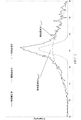
- FIG. 1 shows the results of peak separation of the P2p peak in the XPS spectrum of the carbon catalyst obtained in Example 1.
- P1 indicates the peak P 130.0
- P2 indicates the peak P 132.5
- P3 indicates the peak P 133.2
- P4 indicates the peak P 133.3
- 9 and “P5” indicates the peak P135.6 .
- FIG. 1 also shows an enlarged view of “P3”.
- the peak intensity of “P5” was so small that it was not visible in FIG.
- FIG. 2A shows the result of peak separation in the XRD diffractogram of the carbon catalyst obtained in Example 1.
- FIG. 2B shows the results of peak separation in the XRD diffractogram of the carbon catalyst obtained in Comparative Example 1.
- FIG. 3 shows the XPS measurement results, XRD measurement results, and oxygen reduction activity measurement results for Examples 1 to 9 and Comparative Examples 1 and 2, respectively.
- the current density i 0.5 (mA / cm 2 ) of the carbon catalysts obtained in Examples 1 to 9 is more remarkable than that of the carbon catalysts obtained in Comparative Examples 1 and 2. It was big. That is, the oxygen reduction activity of the carbon catalysts obtained in Examples 1 to 9 was significantly higher than that of the carbon catalysts obtained in Comparative Examples 1 and 2.
- the performance retention rate (%) of the carbon catalysts obtained in Examples 1 to 9 was significantly larger than that of the carbon catalysts obtained in Comparative Examples 1 and 2. That is, the carbon catalysts obtained in Examples 1 to 9 were superior to the carbon catalysts obtained in Comparative Examples 1 and 2 in terms of durability.
- the P 132.5 / C ratio of the carbon catalysts obtained in Examples 1 to 9 was significantly larger than that of the carbon catalysts obtained in Comparative Examples 1 and 2. . Therefore, the carbon catalysts obtained in Examples 1 to 9 contain a relatively large amount of a specific phosphorus atom showing a peak P 132.5 having a peak top in the range of 132.5 ⁇ 0.3 eV in the XPS measurement. (That is, due to the relatively large P 2 / C ratio), it was considered that excellent oxygen reduction activity and durability were exhibited.
- the carbon catalysts obtained in Examples 1 to 9 had a P 132.5 / P total ratio of 0.3025 or more, which was larger than that of the carbon catalysts obtained in Comparative Examples 1 and 2. .
- the carbon catalyst obtained in Examples 1 to 9 in XRD measurement, the ratio of the peak f broad derived from a low crystalline component is 72.83% greater (more specifically is more than 94.44%), the peak f ratio of narrow less than 27.17% (more specifically derived from the highly crystalline component was 5.56% or less).
- the carbon catalysts obtained in Examples 1, 4, 5, 6, and 8 have a current density i 0.5 and performance compared to the carbon catalysts obtained in Examples 2, 3, 7, and 9.
- the maintenance rate was particularly excellent.
- P 132.5 / C ratio of the carbon catalyst obtained in Example 1,4,5,6,8 (more specifically, 0.0057 or more) 0.0038 greater is, implemented It was larger than that of the carbon catalyst obtained in Examples 2, 3, 7, and 9.
- the P / C ratio of the carbon catalysts obtained in Examples 1, 4, 5, 6, and 8 is more than 0.0080 (more specifically, 0.0100 or more). , 7, 9 and larger than that of the carbon catalyst obtained. Further, the amount (atomic%) of phosphorus atoms in the carbon catalysts obtained in Examples 1, 4, 5, 6, and 8 is more than 0.65 (more specifically, 0.79 or more). It was larger than that of the carbon catalyst obtained in Examples 2, 3, 7, and 9.
Landscapes
- Chemical & Material Sciences (AREA)
- Chemical Kinetics & Catalysis (AREA)
- Engineering & Computer Science (AREA)
- Materials Engineering (AREA)
- Electrochemistry (AREA)
- General Chemical & Material Sciences (AREA)
- Organic Chemistry (AREA)
- Composite Materials (AREA)
- Catalysts (AREA)
- Manufacturing & Machinery (AREA)
- Inert Electrodes (AREA)
Priority Applications (5)
| Application Number | Priority Date | Filing Date | Title |
|---|---|---|---|
| CA3045977A CA3045977C (en) | 2016-12-06 | 2017-11-30 | COAL CATALYST, AND ELECTRODE AND BATTERY CONTAINING THEM |
| US16/464,996 US11276865B2 (en) | 2016-12-06 | 2017-11-30 | Carbon catalyst, and electrode and battery containing same |
| CN201780075751.1A CN110049814B (zh) | 2016-12-06 | 2017-11-30 | 碳催化剂以及含有所述碳催化剂的电极和电池 |
| KR1020197017678A KR102433923B1 (ko) | 2016-12-06 | 2017-11-30 | 탄소촉매, 그리고 이것을 포함하는 전극 및 전지 |
| EP17878288.4A EP3552698B1 (en) | 2016-12-06 | 2017-11-30 | Carbon catalyst, and electrode and battery containing same |
Applications Claiming Priority (2)
| Application Number | Priority Date | Filing Date | Title |
|---|---|---|---|
| JP2016-236828 | 2016-12-06 | ||
| JP2016236828A JP6857878B2 (ja) | 2016-12-06 | 2016-12-06 | 炭素触媒並びにこれを含む電極及び電池 |
Publications (1)
| Publication Number | Publication Date |
|---|---|
| WO2018105472A1 true WO2018105472A1 (ja) | 2018-06-14 |
Family
ID=62491020
Family Applications (1)
| Application Number | Title | Priority Date | Filing Date |
|---|---|---|---|
| PCT/JP2017/042951 Ceased WO2018105472A1 (ja) | 2016-12-06 | 2017-11-30 | 炭素触媒並びにこれを含む電極及び電池 |
Country Status (7)
| Country | Link |
|---|---|
| US (1) | US11276865B2 (enExample) |
| EP (1) | EP3552698B1 (enExample) |
| JP (1) | JP6857878B2 (enExample) |
| KR (1) | KR102433923B1 (enExample) |
| CN (1) | CN110049814B (enExample) |
| CA (1) | CA3045977C (enExample) |
| WO (1) | WO2018105472A1 (enExample) |
Families Citing this family (2)
| Publication number | Priority date | Publication date | Assignee | Title |
|---|---|---|---|---|
| JP7175857B2 (ja) * | 2019-08-02 | 2022-11-21 | 日清紡ホールディングス株式会社 | 金属担持触媒、電池電極及び電池 |
| CN113363508B (zh) * | 2021-02-02 | 2022-10-28 | 井冈山大学 | 一种燃料电池用电催化剂及其制备方法 |
Citations (5)
| Publication number | Priority date | Publication date | Assignee | Title |
|---|---|---|---|---|
| JPH0574457A (ja) * | 1991-03-02 | 1993-03-26 | Sony Corp | 負極材料及びその製造方法並びにこれを用いた非水電解液電池 |
| JPH1040913A (ja) * | 1996-07-24 | 1998-02-13 | Osaka Gas Co Ltd | リチウム二次電池負極用炭素材及びその製造方法並びにリチウム二次電池 |
| JP2013209261A (ja) * | 2012-03-30 | 2013-10-10 | Toshiba Corp | 炭素電極とその製造方法およびそれを用いた光電変換素子 |
| JP2013208597A (ja) | 2012-03-30 | 2013-10-10 | Toshiba Corp | 酸素還元触媒と酸素還元触媒を用いた電気化学セル |
| WO2016088716A1 (ja) * | 2014-12-05 | 2016-06-09 | 日清紡ホールディングス株式会社 | 炭素触媒、電極及び電池 |
Family Cites Families (4)
| Publication number | Priority date | Publication date | Assignee | Title |
|---|---|---|---|---|
| WO1992016026A1 (fr) | 1991-03-02 | 1992-09-17 | Sony Corporation | Materiau d'electrode negative, procede de fabrication de ce materiau, et batterie electrolytique non aqueuse composee de ce materiau |
| JP5149364B2 (ja) * | 2010-11-08 | 2013-02-20 | 国立大学法人群馬大学 | 炭素触媒及びその製造方法並びにこれを用いた電極及び電池 |
| CN103974900B (zh) * | 2011-12-12 | 2017-03-08 | 松下电器产业株式会社 | 碳系材料、电极催化剂、氧还原电极催化剂、气体扩散电极、水溶液电解装置和制备碳系材料的方法 |
| KR101427343B1 (ko) * | 2012-08-14 | 2014-08-07 | 한국과학기술원 | 질소 이외에 붕소, 인 중에서 선택된 어느 하나 이상의 추가적 도핑에 의해 산소 환원 반응성이 증가된 탄소 촉매의 제조방법 |
-
2016
- 2016-12-06 JP JP2016236828A patent/JP6857878B2/ja active Active
-
2017
- 2017-11-30 CN CN201780075751.1A patent/CN110049814B/zh active Active
- 2017-11-30 WO PCT/JP2017/042951 patent/WO2018105472A1/ja not_active Ceased
- 2017-11-30 CA CA3045977A patent/CA3045977C/en active Active
- 2017-11-30 EP EP17878288.4A patent/EP3552698B1/en active Active
- 2017-11-30 KR KR1020197017678A patent/KR102433923B1/ko active Active
- 2017-11-30 US US16/464,996 patent/US11276865B2/en active Active
Patent Citations (5)
| Publication number | Priority date | Publication date | Assignee | Title |
|---|---|---|---|---|
| JPH0574457A (ja) * | 1991-03-02 | 1993-03-26 | Sony Corp | 負極材料及びその製造方法並びにこれを用いた非水電解液電池 |
| JPH1040913A (ja) * | 1996-07-24 | 1998-02-13 | Osaka Gas Co Ltd | リチウム二次電池負極用炭素材及びその製造方法並びにリチウム二次電池 |
| JP2013209261A (ja) * | 2012-03-30 | 2013-10-10 | Toshiba Corp | 炭素電極とその製造方法およびそれを用いた光電変換素子 |
| JP2013208597A (ja) | 2012-03-30 | 2013-10-10 | Toshiba Corp | 酸素還元触媒と酸素還元触媒を用いた電気化学セル |
| WO2016088716A1 (ja) * | 2014-12-05 | 2016-06-09 | 日清紡ホールディングス株式会社 | 炭素触媒、電極及び電池 |
Non-Patent Citations (2)
| Title |
|---|
| QIAO, XIAOCHANG ET AL.: "Nitrogen, phosphorus and iron doped carbon nanospheres with high surface area and hierarchical porous structure for oxygen reduction", JOURNAL OF POWER SOURCES, vol. 288, 15 August 2015 (2015-08-15), pages 253 - 260, XP029230467, ISSN: 0378-7753, Retrieved from the Internet <URL:https://doi.org/10.1016/j.jpowsour.2015.04.118> * |
| See also references of EP3552698A4 |
Also Published As
| Publication number | Publication date |
|---|---|
| EP3552698A1 (en) | 2019-10-16 |
| EP3552698B1 (en) | 2025-06-04 |
| KR102433923B1 (ko) | 2022-08-18 |
| CN110049814A (zh) | 2019-07-23 |
| CA3045977A1 (en) | 2018-06-14 |
| JP2018089591A (ja) | 2018-06-14 |
| EP3552698A4 (en) | 2020-07-22 |
| KR20190087507A (ko) | 2019-07-24 |
| CA3045977C (en) | 2025-05-27 |
| US11276865B2 (en) | 2022-03-15 |
| CN110049814B (zh) | 2022-06-07 |
| JP6857878B2 (ja) | 2021-04-14 |
| US20190296365A1 (en) | 2019-09-26 |
Similar Documents
| Publication | Publication Date | Title |
|---|---|---|
| Davidson et al. | Spectroscopic studies of nickel (II) and nickel (III) species generated upon thermal treatments of nickel/ceria-supported materials | |
| JP4964292B2 (ja) | 電極及び電池 | |
| Zhang et al. | Iron phthalocyanine and nitrogen-doped graphene composite as a novel non-precious catalyst for the oxygen reduction reaction | |
| JP6097456B2 (ja) | 炭素触媒、電極及び電池 | |
| Sharma et al. | Effects of structural disorder and nitrogen content on the oxygen reduction activity of polyvinylpyrrolidone-derived multi-doped carbon | |
| Chao et al. | Cobalt selenide electrocatalyst supported by nitrogen-doped carbon and its stable activity toward oxygen reduction reaction | |
| Zhan et al. | Platinum nanoparticles decorated robust binary transition metal nitride–carbon nanotubes hybrid as an efficient electrocatalyst for the methanol oxidation reaction | |
| Zhou et al. | Highly dispersed ultrafine Pt nanoparticles on hydrophilic N-doped carbon tubes for improved methanol oxidation | |
| CN109153011B (zh) | 碳催化剂、电池电极、及电池 | |
| JP6800608B2 (ja) | 電池電極、電池電極触媒層用組成物及び電池 | |
| Cha et al. | Facile synthesis of carbon supported metal nanoparticles via sputtering onto a liquid substrate and their electrochemical application | |
| Brotons-Alcázar et al. | Molecular stabilization of chemically exfoliated bare MnPS 3 layers | |
| CN110869121A (zh) | 碳催化剂、电池电极和电池 | |
| Ahmed et al. | Bifunctional electrochemical OER and HER activity of Ta 2 O 5 nanoparticles over Fe 2 O 3 nanoparticles | |
| WO2018105472A1 (ja) | 炭素触媒並びにこれを含む電極及び電池 | |
| Wang et al. | Co/Co 9 S 8 nanoparticles coupled with N, S-doped graphene-based mixed-dimensional heterostructures as bifunctional electrocatalysts for the overall oxygen electrode | |
| Lee et al. | Epitaxial growth of Pd nanoparticles on molybdenum disulfide by sonochemistry and its effects on electrocatalysis | |
| JP5689379B2 (ja) | 触媒担持用担体、触媒担持体、電極及び電池 | |
| Cao et al. | MOF-Derived Multi-Metal Sulfides with Optimized d-Band Center Enable Long-Term Stable Li–O2 Batteries | |
| JP6189197B2 (ja) | 炭素触媒及びその製造方法並びにこれを用いた電極及び電池 | |
| JP7812252B2 (ja) | 金属担持触媒及びその製造方法並びに電極及び電池 | |
| JP7720272B2 (ja) | 金属担持触媒、電極及び電池 | |
| Zhou | Ultrathin Two-Dimensional Nanomaterials as Electrocatalysts for Water Splitting | |
| Wang | Hydrogen and nitrogen plasma treated materials with disordered surface layer used for energy storage and conversion devices | |
| Choi | Nanostructured Materials Supported Oxygen Reduction Catalysts in Polymer Electrolyte Membrane Fuel Cells |
Legal Events
| Date | Code | Title | Description |
|---|---|---|---|
| 121 | Ep: the epo has been informed by wipo that ep was designated in this application |
Ref document number: 17878288 Country of ref document: EP Kind code of ref document: A1 |
|
| ENP | Entry into the national phase |
Ref document number: 3045977 Country of ref document: CA |
|
| NENP | Non-entry into the national phase |
Ref country code: DE |
|
| ENP | Entry into the national phase |
Ref document number: 20197017678 Country of ref document: KR Kind code of ref document: A |
|
| ENP | Entry into the national phase |
Ref document number: 2017878288 Country of ref document: EP Effective date: 20190708 |
|
| WWG | Wipo information: grant in national office |
Ref document number: 2017878288 Country of ref document: EP |