WO2018105361A1 - スパークプラグ - Google Patents
スパークプラグ Download PDFInfo
- Publication number
- WO2018105361A1 WO2018105361A1 PCT/JP2017/041482 JP2017041482W WO2018105361A1 WO 2018105361 A1 WO2018105361 A1 WO 2018105361A1 JP 2017041482 W JP2017041482 W JP 2017041482W WO 2018105361 A1 WO2018105361 A1 WO 2018105361A1
- Authority
- WO
- WIPO (PCT)
- Prior art keywords
- particles
- layer
- spark plug
- ferrite
- magnetic particles
- Prior art date
- Legal status (The legal status is an assumption and is not a legal conclusion. Google has not performed a legal analysis and makes no representation as to the accuracy of the status listed.)
- Ceased
Links
Images
Classifications
-
- H—ELECTRICITY
- H01—ELECTRIC ELEMENTS
- H01T—SPARK GAPS; OVERVOLTAGE ARRESTERS USING SPARK GAPS; SPARKING PLUGS; CORONA DEVICES; GENERATING IONS TO BE INTRODUCED INTO NON-ENCLOSED GASES
- H01T13/00—Sparking plugs
- H01T13/20—Sparking plugs characterised by features of the electrodes or insulation
- H01T13/39—Selection of materials for electrodes
Definitions
- the present invention relates to a spark plug, and more particularly to a spark plug incorporating a magnetic material.
- the present invention has been made to solve the above-described problems, and an object thereof is to provide a spark plug that can suppress radio noise.
- the insulator has an axial hole extending in the direction of the axis from the front end side to the rear end side. At least a part of the center electrode is inserted on the front end side of the shaft hole, and at least a part of the terminal fitting is inserted on the rear end side of the shaft hole.
- the connecting portion connects the terminal fitting and the center electrode within the shaft hole.
- the connecting portion includes a first layer including a plurality of first magnetic particles each including a first particle that is a ferrite particle and a first conductive material that covers the first particle; a second particle that is a ferrite particle; And a second layer including a plurality of second magnetic particles each including a second conductive material covering the second particles.
- the second layer including the second particles having a Curie temperature lower than the Curie temperature of the first particles is disposed on the rear end side of the first layer.
- the second layer containing the second particles having a Curie temperature lower than the Curie temperature of the first particles is disposed on the rear end side of the first layer.
- the first magnetic particles and the second magnetic particles have an effect of effectively suppressing radio noise.
- ferrite exhibits a noise attenuation effect by blocking or absorbing a frequency band that causes radio noise in the discharge current.
- ferrite generally has a higher noise attenuation effect as the ferrite has a lower Curie temperature.
- the magnetization gradually decreases and loses magnetism at the Curie temperature. Since the temperature of the connection part during the operation of the spark plug is lower on the rear end side than on the front end side of the connection part, the second layer containing the second particles having a Curie temperature lower than the Curie temperature of the first particles By arranging the at the rear end side of the first layer, the noise attenuation effect by the second magnetic particles can be effectively obtained.
- the first particles have a Curie temperature of 300 ° C. or higher, and the second particles have a Curie temperature of 200 ° C. or higher and lower than 300 ° C. Therefore, in addition to the effect of claim 1, there is an effect that the reliability of the noise attenuation effect obtained when the spark plug is operated can be improved.
- the first layer and the second layer have at least one of silicon, boron, and phosphorus around the plurality of first magnetic particles and the plurality of second magnetic particles,
- a ceramic phase including at least one of an alkali metal and an alkaline earth metal is provided.
- the voids in the ceramic phase can be reduced, so that the discharge generated in the voids in the ceramic phase can be suppressed. Therefore, in addition to the effect of Claim 1 or 2, there exists an effect which can suppress the durable fall by the discharge which arises in a ceramic phase.
- the ceramic phase contains ferrite different from the first particles and the second particles, in addition to the noise attenuation effect by the first particles and the second particles, Noise attenuation effect by ferrite can be obtained. Therefore, in addition to the effect of the third aspect, the noise attenuation effect can be improved.
- the first seal portion of the connection portion connects the first layer and the center electrode
- the second seal portion of the connection portion connects the second layer and the terminal fitting.
- the shortest length in the axial direction from the position at which the first magnetic particles included in the first layer are in contact with the first seal portion to the position at which the second magnetic particles included in the second layer are in contact with the second seal portion is It is 15 mm or more.
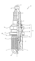
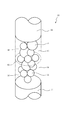
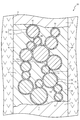
- connection part It is a half sectional view of the spark plug in one embodiment of the present invention. It is a schematic diagram of a connection part. It is typical sectional drawing of a connection part.
- FIG. 1 is a half sectional view of a spark plug 10 according to an embodiment of the present invention.
- the lower side of the drawing is referred to as the front end side of the spark plug 10
- the upper side of the drawing is referred to as the rear end side of the spark plug 10.
- the spark plug 10 includes an insulator 11, a center electrode 14, and a terminal fitting 15. *
- the insulator 11 is a member formed of alumina or the like that is excellent in mechanical properties and insulation at high temperatures, and has a shaft hole 12 penetrating along the axis O.
- the shaft hole 12 is provided with a stepped portion 13 on the distal end side whose inner diameter gradually decreases toward the distal end.
- the center electrode 14 is a rod-shaped member extending along the axis O, and copper or a core material mainly composed of copper is covered with nickel or a nickel-based alloy. The center electrode 14 is locked to the step portion 13 of the shaft hole 12, and the tip is exposed from the shaft hole 12.
- the terminal fitting 15 is a rod-like member to which a high voltage cable (not shown) is connected, and is formed of a conductive metal material (for example, low carbon steel).
- the terminal fitting 15 is fixed to the rear end of the insulator 11 with the front end side being press-fitted into the shaft hole 12.
- the insulator 11 has a metal shell 16 swaged and fixed to the distal end side of the outer periphery with a gap in the direction of the axis O from the terminal metal 15.
- the metal shell 16 is a substantially cylindrical member formed of a conductive metal material (for example, low carbon steel).
- the metal shell 16 includes a seat portion 17 that projects like a flange outward in the radial direction, and a screw portion 18 that is formed on the outer peripheral surface on the tip side of the seat portion 17.
- the metal shell 16 is fixed by fastening a screw portion 18 into a screw hole of an internal combustion engine (cylinder head) 60. *
- the ground electrode 19 is a metal (for example, nickel-base alloy) member joined to the tip of the metal shell 16.
- the ground electrode 19 is formed in a rod shape, the tip side is bent and faces the center electrode 14.
- the ground electrode 19 forms a spark gap with the center electrode 14.
- connection portion 20 is a portion that electrically connects the center electrode 14 and the terminal fitting 15, and is disposed in the shaft hole 12.
- the connection portion 20 includes a first layer 30 and a second layer 40 including a magnetic body and a conductor, a first seal portion 21 that contacts the center electrode 14 and the first layer 30, a second layer 40, and a terminal fitting. And a second seal portion 22 in contact with 15.
- the first seal portion 21 and the second seal portion 22 are made of, for example, glass particles such as B 2 O 3 —SiO 2 , BaO—B 2 O 3 , SiO 2 —B 2 O 3 —CaO—BaO, and metal particles It is formed of a composition containing (Cu, Fe, etc.) and has conductivity.
- the first layer 30 and the second layer 40 are parts for suppressing radio noise generated during discharge.
- FIG. 2 is a schematic diagram of the connecting portion 20.
- the connection part 20 the 1st seal part 21, the 1st layer 30, the 2nd layer 40, and the 2nd seal part 22 are connected in series from the front end side to the back end side.
- the first layer 30 includes a plurality of first magnetic particles 31 having conductivity, and a ceramic phase 35 that fixes the first magnetic particles 31.
- the second layer 40 includes a plurality of second magnetic particles 41 having conductivity and a ceramic phase 45 that fixes the second magnetic particles 41. In the vicinity of the boundary 50 between the first layer 30 and the second layer 40, the first magnetic particles 31 and the second magnetic particles 41 are mixed. *
- the first magnetic particles 31 are in contact with each other, and in the second layer 40, the second magnetic particles 41 are in contact with each other. Some of the first magnetic particles 31 are in contact with the first seal portion 21, and some of the second magnetic particles 41 are in contact with the second seal portion 22. In the vicinity of the boundary 50 between the first layer 30 and the second layer 40, the first magnetic particles 31 and the second magnetic particles 41 are in contact with each other to electrically connect the first seal portion 21 and the second seal portion 22. A three-dimensional conductive path is formed. The conductive paths formed by the first magnetic particles 31 and the second magnetic particles 41 are fixed by the ceramic phases 35 and 45. *
- FIG. 3 is a schematic cross-sectional view of the connecting portion 20.
- the first magnetic particles 31 included in the first layer 30 include first particles 32 that are ferrite (soft magnetic material) particles and a first conductive material 33 that covers the first particles 32.
- the second magnetic particles 41 included in the second layer 40 include second particles 42 that are ferrite (soft magnetic material) particles and a second conductive material 43 that covers the second particles 42. *
- the first particles 32 and the second particles 42 are made of, for example, a spinel type or garnet type ferrite.
- As the first particles 32 and the second particles 42 secondary particles obtained by agglomerating a plurality of primary particles of ferrite, primary particles obtained by surface diffusion of ferrite and grain growth, and the like are used. Ferrite blocks or absorbs a frequency band that causes radio noise in the discharge current flowing between the first seal portion 21 and the second seal portion 22 during discharge. *
- Ferrite for example, Mn X Fe 2-X O 4 , Ni X Fe 2-X O 4, Cu X Fe 2-X O 4, Zn X Fe 2-X O 4, Co X Fe 2-X O 4, Fe X Fe 2-X O 4, Ca X Fe 2-X O 4, Mg X Fe 2-X O 4, Y 3 Fe 5 O 12, Dy 3 Fe 5 O 12, Lu 3 Fe 5 O 12, Yb 3 Fe 5 O 12, Tm 3 Fe 5 O 12, Er 3 Fe 5 O 12, Ho 3 Fe 5 O 12, Tb 3 Fe 5 O 12, Gd 3 Fe 5 O 12, Sm 3 Fe 5 O 12 , etc.
- fractional ferrite examples thereof include composite ferrites such as (Mn 1-X Zn X ) Fe 2 O 4 and (Ni 1-X Zn X ) Fe 2 O 4 in which these unitary ferrites are solid-solved with each other at an arbitrary ratio.
- composite ferrites such as (Mn 1-X Zn X ) Fe 2 O 4 and (Ni 1-X Zn X ) Fe 2 O 4 in which these unitary ferrites are solid-solved with each other at an arbitrary ratio.
- One or more of these ferrites can be appropriately selected and used.
- the average particle diameter of the first particle 32 and the second particle 42 is an average diameter of a sphere calculated using a projected area obtained by binarizing an SEM image (acceleration voltage 15 kV) by image processing.
- the first conductive material 33 is a conductor that covers the surfaces of the first particles 32
- the second conductive material 43 is a conductor that covers the surfaces of the second particles 42.
- the first conductive material 33 and the second conductive material 43 are made of, for example, a metal such as Ni, Cu, Sn, Fe, Inconel (INCONEL is a registered trademark), or a conductive or semiconductive material such as LaMnO 3 , SrTiO 3 , SrCrO 3. Composite oxides, carbon, carbon compounds such as Cr 3 C 2 , and TiC are used. One or more of these conductive materials can be appropriately selected and used.
- the conductors of the first conductive material 33 and the second conductive material 43 may be the same type or different types.
- the particles of the first conductive material 33 and the second conductive material 43 are mixed and stirred together with the first particles 32 and the second particles 42 to mechanically adhere to the surfaces of the first particles 32 and the second particles 42.
- the particles of the first conductive material 33 and the second conductive material 43 are attached to the surfaces of the first particles 32 and the second particles 42 using a binder or the like, or by electroless plating.
- a means for causing the second conductive material 43 to precipitate on the surfaces of the first particles 32 and the second particles 42 can be mentioned.
- the first magnetic particle 31 and the second magnetic particle 41 are electrically conductive layer portions where the first conductive material 33 and the second conductive material 43 are in contact with each other between the adjacent first magnetic particle 31 and the second magnetic particle 41. 34 and 44 are formed.
- the conductive layer portions 34 and 44 are configured such that the first conductive material 33 and the second conductive material 43 are simply in contact, the first conductive material 33 and the second conductive material 43 are fused, and the like. Any form of forming a conductive path is included.
- the first magnetic particles 31 and the second magnetic particles 41 are connected by the conductive layer portions 34 and 44, and a three-dimensional conductive path that electrically connects the first seal portion 21 and the second seal portion 22 is the first layer 30. And formed in the second layer 40. *
- the discharge current flowing through the first layer 30 and the second layer 40 during the discharge causes the first conductive material 33, the second conductive material 43, and the conductive layer portions 34 and 44 of the first magnetic particles 31 and the second magnetic particles 41 to flow. Pass through.
- the current in the frequency band that causes radio noise is the ferrite constituting the first particles 32 and the second particles 42. It is blocked or absorbed by the impedance and magnetic loss. As a result, radio noise can be suppressed.
- the ferrite of the second particles 42 one having a Curie temperature lower than the Curie temperature of the ferrite of the first particles 32 is selected.
- the ferrite gradually decreases in magnetization as the temperature rises, and loses magnetism at the Curie temperature.
- ferrite having a lower Curie temperature has a higher noise attenuation effect.
- the temperature of the connecting portion 20 during operation of the spark plug 10 attached to the internal combustion engine 60 is lower at the rear end side than at the front end side of the connecting portion 20 away from the internal combustion engine 60.
- the second particle 42 is arranged in the second layer 40, so that the noise attenuation effect can be obtained as compared with the case where the first particle 32 having a higher Curie temperature than the second particle 42 is arranged in the second layer 40. Can be improved. Furthermore, since the first particles 32 having a Curie temperature higher than the Curie temperature of the second particles 42 are arranged in the first layer 30 whose temperature rises higher than that of the second layer 40 when the spark plug 10 is operated, the first magnetism is increased. A noise attenuation effect by the particles 31 is also obtained. Therefore, radio noise can be suppressed by the first magnetic particles 31 and the second magnetic particles 41. Specifically, it is preferable that ferrite having a Curie temperature of 300 ° C.
- the first particles 32 and the second particles 42 are spinel-type ferrites, and the first particles 32 and the second particles 42 are controlled by controlling the atoms entering the A position (8a point), B position (16d point), and 32c point of the lattice points.
- the characteristics of the second particles 42 can be controlled.
- Spinel type ferrite represented by the molecular formula of M 2+ Fe 2 3+ O 4 2 ⁇ (M 2+ is a divalent metal ion) has two types of positions A and B in the position where M 2+ and Fe 3+ enter, O 2- enters the 32c point.
- the M of the ferrite of the first particle 32 and the second particle 42 is one or more of Zn, Cd and one or more of Ni, Mn, Cu, Fe, Mg, Co (hereinafter referred to as “other metal”). ).
- the ferrite of the first particle 32 and the second particle 42 makes other metals the same. In this state, the ratio (mol%) of the total amount of Zn and Cd in the first particles 32 is less than the ratio (mol%) of the total amount of Zn and Cd in the second particles 42, which is suitable for noise attenuation.
- the first particles 32 and the second particles 42 can be controlled.
- the Curie temperature of the first particles 32 is made higher than the Curie temperature of the second particles 42.
- the noise attenuation effect of the second particles 42 can be improved. That is, the characteristics of the first particles 32 and the second particles 42 can be controlled.
- the first magnetic particles 31 and the first seal portion 21 included in the first layer 30 are in contact with each other at a plurality of positions 51 and 52.
- the second magnetic particles 41 and the first magnetic particles 31 included in the second layer 40 are in contact with each other at a plurality of positions 53 and 54.
- the second magnetic particles 41 and the second seal portion 22 are in contact with each other at a plurality of positions 55 and 56.
- the shortest length in the axis O direction from the position 51, 52 to the position 55, 56 is the length in the axis O direction from the position 52 to the position 56.
- This length is the total axial length of the first layer 30 and the second layer 40. This total length is preferably 15 mm or more. This is because the noise attenuation effect by the first magnetic particles 31 and the second magnetic particles 41 can be obtained stably.
- the length in the axis O direction from the position 52 to the positions 53 and 54 is The axial length of the first layer 30 is assumed. This length is preferably 7 mm or more. This is because the noise attenuation effect by the first magnetic particles 31 can be obtained stably.
- the length in the axis O direction from the position 56 to the positions 53 and 54 is the second layer.
- the length in the axial direction is 40. This length is preferably 7 mm or more. This is because the noise attenuation effect by the second magnetic particles 41 can be obtained stably.
- the positions 51 to 56 are obtained from a cross section parallel to the axis O. Since the first magnetic particle 31 and the second magnetic particle 41 form a conductive path that is three-dimensionally connected, a plurality of cross sections with different positions (depths) are formed in the depth direction orthogonal to the axis O, and exist in each cross section. By observing the first magnetic particles 31 and the second magnetic particles 41, the positions 51 to 56 can be specified. *
- the first layer 30 exists on the rear end side with respect to the rear end of the screw portion 18.
- the rear end of the screw portion 18 is an end portion (neck lower portion) on the seat portion 17 side of the screw portion 18 and is an end of the complete screw portion. Since the metal shell 16 is connected to the internal combustion engine 60 by the screw portion 18, the metal shell 16 dissipates the heat of the insulator 11 during the operation of the spark plug 10 from the screw portion 18 to the internal combustion engine 60. Since the first layer 30 exists on the rear end side with respect to the rear end of the screw portion 18, the temperature of the first layer 30 is higher than that in the case where the first layer 30 exists on the front end side with respect to the rear end of the screw portion 18. Can be lowered. Since a decrease in magnetization of the first particles 32 due to an increase in the temperature of the first particles 32 included in the first layer 30 can be suppressed, the noise attenuation effect by the first magnetic particles 31 can be improved. *
- the ceramic phases 35 and 45 are portions for fixing the first magnetic particles 31 and the second magnetic particles 41 to the first layer 30 and the second layer 40.
- the ceramic phases 35 and 45 can employ any material as long as strength and insulation at high temperatures can be secured to some extent.
- SiO 2 , Al 2 O 3 or the like is used for the ceramic phases 35 and 45.
- crystallized glass such as Li 2 O—Al 2 O 3 —SiO 2 glass can be used for the ceramic phases 35 and 45.
- the ceramic phases 35 and 45 preferably include at least one of silicon (Si), boron (B), and phosphorus (P) and at least one of alkali metals and alkaline earth metals. . Since the ceramic phases 35 and 45 can be vitrified by lowering the softening point of the ceramic phases 35 and 45, the first magnetic particles 31 and the second magnetic particles 41 can be firmly fixed, and impact resistance can be secured. is there. *
- the ceramic phases 35 and 45 preferably contain ferrite. This is because, in addition to the noise attenuation effect by the first magnetic particles 31 and the second magnetic particles 41, the noise attenuation effect by the ferrite contained in the ceramic phases 35 and 45 can be obtained.
- the ferrite contained in the ceramic phases 35 and 45 is, for example, Mn X Fe 2 -X O 4 , Ni X Fe 2 -X O 4 , Cu X Fe as in the ferrite constituting the first particles 32 and the second particles 42.
- ferrite having a Curie temperature of 300 ° C. or higher is disposed in the ceramic phase 35 of the first layer 30, and ferrite having a Curie temperature of 200 ° C. or higher and lower than 300 ° C. is disposed in the ceramic phase 45 of the second layer 40.
- ferrite having a Curie temperature of 300 ° C. or higher is disposed in the ceramic phase 35 of the first layer 30, and ferrite having a Curie temperature of 200 ° C. or higher and lower than 300 ° C. is disposed in the ceramic phase 45 of the second layer 40.
- the spark plug 10 is manufactured by the following method, for example. First, the center electrode 14 is inserted into the shaft hole 12 of the insulator 11, and the center electrode 14 is locked by the step portion 13. Next, the raw material powder of the first seal portion 21 is put through the shaft hole 12 and filled around the center electrode 14. The raw material powder of the first seal portion 21 filled in the shaft hole 12 is pre-compressed using a compression rod (not shown). *
- the raw material powder of the first layer 30 obtained by mixing the raw material powder of the ceramic phase 35 and the first magnetic particles 31 is filled on the formed raw material powder of the first seal portion 21.
- the first magnetic particles 31 are formed by attaching particles of the first conductive material 33 to secondary particles (first particles 32) in which primary particles of ferrite are aggregated using a binder, or by electroless plating. It is obtained by precipitating the substance 33.
- the raw material powder of the first layer 30 filled in the shaft hole 12 is pre-compressed using a compression rod (not shown). *
- the raw material powder of the second layer 40 obtained by mixing the raw material powder of the ceramic phase 45 and the second magnetic particles 41 is filled on the raw material powder of the first layer 30.
- the second magnetic particles 41 are formed by adhering particles of the second conductive material 43 to secondary particles (second particles 42) in which primary particles of ferrite are aggregated using a binder, or by electroless plating. It is obtained by precipitating the substance 43.
- the raw material powder of the second layer 40 filled in the shaft hole 12 is pre-compressed using a compression rod (not shown). *
- the raw material powder of the second seal portion 22 is filled on the raw material powder of the second layer 40.
- the raw material powder of the second seal portion 22 filled in the shaft hole 12 is pre-compressed using a compression rod (not shown). *
- the insulator 11 filled with the raw material powder of the first seal part 21, the first layer 30, the second layer 40, and the second seal part 22 in this order is transferred into the furnace, for example, the first seal part 21 and the second seal.
- the terminal fitting 15 is press-fitted into the shaft hole 12 of the insulator 11, and the raw material powder of the first seal portion 21, the first layer 30, the second layer 40, and the second seal portion 22 is pivoted by the tip of the terminal fitting 15. Compress in the direction.
- each raw material powder is compressed and sintered, and the first seal portion 21, the first layer 30, the second layer 40, and the second seal portion 22 are formed inside the insulator 11.
- the insulator 11 is transferred to the outside of the furnace, and the metal shell 16 is assembled to the outer periphery of the insulator 11. After joining the ground electrode 19 to the metal shell 16, the ground electrode 19 is bent so that the tip of the ground electrode 19 faces the center electrode 14 to obtain the spark plug 10.
- the porosity of the ceramic phases 35 and 45 can be adjusted by the load when the raw material powders of the first layer 30 and the second layer 40 are compressed in the axial direction.
- the porosity can also be adjusted by changing the temperature at which the first seal part 21 and the second seal part 22 are softened or changing the type of glass component contained in the raw material powder of the ceramic phases 35 and 45.
- Table 1 shows the first particles 32, the first conductive material 33 (referred to as “first material” in the table), the second particles 42, the second conductive material 43 (shown in the table) of the prepared samples 1 to 28. Is expressed as “second material”), Curie temperature (Tc), axial length and length of each layer, difference in composition of ferrite, inclusions (elements) other than Al 2 O 3 in ceramic phases 35 and 45, and The composition of the ferrite contained in the ceramic phases 35 and 45 is shown.
- the composition of the first particles 32 and the second particles 42 was calculated and specified by SEM-EDS (energy dispersive X-ray spectroscopy).
- the composition of the first conductive material 33 and the second conductive material 43 was specified by EPMA (Electron Probe Micro Analyzer).
- the first particles 32, the second particles 42, the first conductive material 33, and the second conductive material 43 may contain trace amounts (for example, about 1 ppm) of various impurities mixed in the manufacturing process.
- the Curie temperatures of the first particles 32 and the second particles 42 were obtained by preparing test pieces having the same composition as the ferrite calculated and identified using SEM-EDS, and measuring them with a VSM (Vibrating Sample Magnetometer). *
- the axial length and total length of the first layer 30 and the second layer 40 are determined by observing a plurality of polished cross sections of the first layer 30 and the second layer 40 parallel to the axis using an SEM.
- the positions where the first magnetic particles 31 and the second magnetic particles 41 are in contact with the first seal portion 21 and the second seal portion 22 are three-dimensionally specified, and the axial distances thereof are calculated and obtained.
- the difference in composition is a value obtained by subtracting the ratio (mol%) of the total amount of Zn and Cd in the first particles 32 from the ratio (mol%) of the total amount of Zn and Cd in the second particles 42.
- the first particle 32 and the second particle 42 are spinel type ferrite represented by a molecular formula of M 2+ Fe 2 3+ O 4 2 ⁇ (M 2+ is a divalent metal ion), and M is either Zn or Cd or Sample 5 in which any one and one or more of Ni, Mn, Cu, Fe, Mg, Co (other metals) and the other metals of the first particles 32 and the second particles 42 are the same.
- the compositional difference was calculated for ⁇ 22,28.
- the inclusions (elements) other than Al 2 O 3 in the ceramic phases 35 and 45 were specified from the raw material powder of the ceramic phases 35 and 45.
- the inclusion (element) may be specified by analyzing the cross sections of the ceramic phases 35 and 45 using ICP, EPMA, or the like.
- the ceramic phases 35 and 45 of the samples whose inclusions (elements) are not shown in Table 1 were Al 2 O 3 . In Table 1, only elements corresponding to silicon, boron, phosphorus, alkali metal and alkaline earth metal are shown.
- the content of alkali metal or alkaline earth metal in the ceramic phases 35 and 45 was in the range of 0.1 to 9 wt%. This content rate is a content rate obtained by converting the amount of alkali metal or alkaline earth metal into an oxide of alkali metal or alkaline earth metal.
- the ceramic phases 35 and 45 may contain various impurities (for example, about 1 ppm) mixed in the manufacturing process. *
- the composition of the ferrite contained in the ceramic phases 35 and 45 was specified by SEM-EDS.
- the content of ferrite in the ceramic phases 35 and 45 was in the range of 5 to 50 wt%.
- the distance of the spark gap between the center electrode 14 and the ground electrode 19 of each sample was adjusted to 0.9 mm ⁇ 0.01 mm, and a voltage of 25 kV was applied with each sample stored in a 400 ° C. chamber.
- the test was performed by applying a discharge between the terminal fitting 15 and the metal shell 16. After conducting the test for discharging at a rate of 60 times per second for 100 hours, the level of the discharge current after the test and the level of the discharge current before the test were measured. *
- the level of the discharge current was measured according to JASO D002-2 (2004) “Automobile-Radio noise characteristics—Part 2: Measuring method of preventer: Current method”. Specifically, the distance of the spark gap between the center electrode 14 and the ground electrode 19 of each sample is adjusted to 0.9 mm ⁇ 0.01 mm, and the voltage within the range of 13 kV to 16 kV is adjusted to the terminal fitting 15 and the metal shell 17. It was applied during the discharge. A current probe is used to measure the current flowing through the terminal fitting 15 during discharge, and the level of the discharge current at 30 MHz, 100 MHz, 250 MHz, and 500 MHz (converted value (unit: dB) with respect to a predetermined reference) is calculated, and the average of the four The value was determined. Moreover, the change rate (%) of the average value after the test with respect to the average value before the test was calculated. Table 2 shows the results. *
- Sample 1 includes the first layer 30 and the second layer 40, and the Curie temperature of the first particles 32 is higher than the Curie temperature of the second particles 42. -22 are lower in the level of the discharge current than the samples 23-26 that do not have the second layer 40 and the samples 27, 28 in which the Curie temperature of the first particles 32 is lower than the Curie temperature of the second particles 42. I was able to. Since Samples 1 to 22 can reduce the level of the current in the high frequency band that causes radio noise, it is clear that radio noise can be suppressed. *
- the axial lengths of the first layer 30 and the second layer 40 were each 7 mm or more. In order to reduce the level of the discharge current, it has been confirmed that the axial length of the first layer 30 and the axial length of the second layer 40 are preferably 7 mm or more.
- Samples 5 to 22 are samples in which spinel ferrite represented by the molecular formula of M 2+ Fe 2 3+ O 4 2 ⁇ (M 2+ is a divalent metal ion) is used for the first particles 32 and the second particles 42. , Zn, and Cd, and one or more of the same metal ions of Ni, Mn, Cu, Fe, Mg, and Co in the first particle 32 and the second particle 42.
- the ratio of the total amount of Zn and Cd in the second particles 42 (mol%) is subtracted from the ratio of the total amount of Zn and Cd in the first particles 32 (mol%).
- the Curie temperature of the first particles 32 can be made higher than the Curie temperature of the second particles 42 while the noise attenuation effect of the second particles 42 can be improved.
- Samples 5 to 22 were able to reduce the level of the discharge current compared to Samples 1 to 4.
- Samples 15 to 22 containing ferrite in ceramic phases 35 and 45 were able to reduce the level of discharge current compared to samples 1 to 14 not containing ferrite in ceramic phases 35 and 45.
- the effect of suppressing radio noise can be further improved because the ferrite of the ceramic phases 35 and 45 can further reduce the current level in the high frequency band causing radio noise.
- samples 19 to 22 in which the total length (shortest length) in the axial direction of the first layer 30 and the second layer 40 was 15 mm or more the level of the discharge current could be further reduced. Therefore, it is clear that samples 19 to 22 can further improve the noise attenuation effect.
- the length of the first layer 30 in the axial direction and the length of the second layer 40 in the axial direction are each 7 mm or more, so it is presumed that the noise attenuation effect could be secured.
- samples 12 to 22 containing at least one of Si, B, and P and at least one of alkali metal and alkaline earth metal in ceramic phases 35 and 45 are: It was confirmed that the rate of change was small and the durability was excellent. *
- the insulator 11 in which the raw material powder of the first seal portion 21, the first layer 30, the second layer 40, and the second seal portion 22 is filled in the shaft hole 12 is used as the furnace.
- the case where it heats inside was illustrated, it is not necessarily restricted to this.
- the raw material powder of the first seal portion 21, the fired first layer 30 and second layer 40, and the raw material powder of the second seal portion 22 are sequentially filled into the shaft hole 12 of the insulator 11, and the insulator In a state where 11 is heated in the furnace, the terminal fitting 15 is pressed into the shaft hole 12 to form the connection portion 20.
- the spark plug 10 in which the ground electrode 19 is opposed to the tip of the center electrode 14 has been described.
- the structure of the spark plug is not necessarily limited thereto. Examples of other structures of the spark plug include a spark plug in which the ground electrode 19 faces the side surface of the center electrode 14 and a multipolar spark plug in which a plurality of ground electrodes 19 are joined to the metal shell 17.
Landscapes
- Spark Plugs (AREA)
Abstract
電波ノイズを抑制できるスパークプラグを提供すること。絶縁体の軸孔の先端側に中心電極の少なくとも一部が挿入され、絶縁体の軸孔の後端側に端子金具の少なくとも一部が挿入される。端子金具と中心電極とを軸孔内で接続する接続部は、フェライトの粒子である第1粒子と第1粒子を被覆する第1導電性物質とをそれぞれ備える複数の第1磁性粒子を含む第1層と、フェライトの粒子である第2粒子と第2粒子を被覆する第2導電性物質とをそれぞれ備える複数の第2磁性粒子を含む第2層と、を備えている。第1粒子のキュリー温度よりも低いキュリー温度をもつ第2粒子が含まれる第2層を、第1層よりも後端側に配置する。
Description
本発明はスパークプラグに関し、特に磁性体を内蔵したスパークプラグに関するものである。
放電時に発生する電波ノイズを抑えるために、絶縁体に抵抗体を内蔵したスパークプラグがある。また、絶縁体に磁性体を内蔵したスパークプラグも提案されている。
しかしながら、上記従来の技術では、磁性体を用いて電波ノイズを抑制する点について十分な工夫がなされていない。
本発明は上述した問題点を解決するためになされたものであり、電波ノイズを抑制できるスパークプラグを提供することを目的としている。
この目的を達成するために本発明のスパークプラグは、絶縁体は先端側から後端側へと軸線の方向に延びる軸孔を有する。中心電極は軸孔の先端側に少なくとも一部が挿入され、端子金具は軸孔の後端側に少なくとも一部が挿入される。接続部は、端子金具と中心電極とを軸孔内で接続する。接続部は、フェライトの粒子である第1粒子と第1粒子を被覆する第1導電性物質とをそれぞれ備える複数の第1磁性粒子を含む第1層と、フェライトの粒子である第2粒子と第2粒子を被覆する第2導電性物質とをそれぞれ備える複数の第2磁性粒子を含む第2層と、を備えている。第1粒子のキュリー温度よりも低いキュリー温度をもつ第2粒子が含まれる第2層が、第1層よりも後端側に配置される。
請求項1記載のスパークプラグによれば、第1粒子のキュリー温度よりも低いキュリー温度をもつ第2粒子が含まれる第2層が、第1層よりも後端側に配置されるので、キュリー温度が同じフェライトで全てが構成される場合と比較して、第1磁性粒子および第2磁性粒子により電波ノイズを効果的に抑制できる効果がある。
即ち、フェライトは、放電電流のうち電波ノイズの原因となる周波数帯を遮断または吸収してノイズ減衰効果を発揮する。また、フェライトは、一般にキュリー温度が低いフェライトほどノイズ減衰効果が高い。しかし、フェライトの温度が上がると次第に磁化が減少し、キュリー温度で磁性を失う。スパークプラグの作動時の接続部の温度は、接続部の先端側よりも後端側の方が低いので、第1粒子のキュリー温度よりも低いキュリー温度をもつ第2粒子が含まれる第2層を第1層よりも後端側に配置することにより、第2磁性粒子によるノイズ減衰効果を効果的に得ることができる。
請求項2記載のスパークプラグによれば、第1粒子はキュリー温度が300℃以上であり、第2粒子はキュリー温度が200℃以上300℃未満である。よって、請求項1の効果に加え、スパークプラグの作動時に得られるノイズ減衰効果の確実性を向上できる効果がある。
請求項3記載のスパークプラグによれば、第1層および第2層は、複数の第1磁性粒子および複数の第2磁性粒子の周囲に、ケイ素、ホウ素およびリンのうちの少なくとも1種と、アルカリ金属およびアルカリ土類金属のうちの少なくとも1種とを含むセラミック相を備えている。第1磁性粒子および第2磁性粒子を固定するセラミック相にこれらの元素が含まれていない場合に比べて、セラミック相の空隙を少なくできるので、セラミック相の空隙で生じる放電を抑制できる。よって、請求項1又は2の効果に加え、セラミック相で生じる放電による耐久性の低下を抑制できる効果がある。
請求項4記載のスパークプラグによれば、セラミック相は、第1粒子および第2粒子とは異なるフェライトを含有しているので、第1粒子および第2粒子によるノイズ減衰効果に加え、セラミック相のフェライトによるノイズ減衰効果が得られる。よって、請求項3の効果に加え、ノイズ減衰効果を向上できる効果がある。
請求項5記載のスパークプラグによれば、接続部の第1シール部は第1層と中心電極とを接続し、接続部の第2シール部は第2層と端子金具とを接続する。第1層に含まれる第1磁性粒子と第1シール部とが接する位置から、第2層に含まれる第2磁性粒子と第2シール部とが接する位置までの軸線方向の最短の長さは15mm以上である。その結果、請求項1から4のいずれかの効果に加え、第1層と第2層とを加えた軸線方向の長さを確保してノイズ減衰効果を向上できる効果がある。
以下、本発明の好ましい実施形態について添付図面を参照して説明する。図1は本発明の一実施の形態におけるスパークプラグ10の片側断面図である。図1では、紙面下側をスパークプラグ10の先端側、紙面上側をスパークプラグ10の後端側という。スパークプラグ10は、絶縁体11、中心電極14及び端子金具15を備えている。
絶縁体11は、機械的特性や高温下の絶縁性に優れるアルミナ等により形成された部材であり、軸線Oに沿って貫通する軸孔12が形成されている。軸孔12は、先端に向かって内径が次第に小さくなる段部13が先端側に設けられている。
中心電極14は、軸線Oに沿って延びる棒状の部材であり、銅または銅を主成分とする芯材がニッケル又はニッケル基合金で覆われている。中心電極14は、軸孔12の段部13に係止され、先端が軸孔12から露出する。
端子金具15は、高圧ケーブル(図示せず)が接続される棒状の部材であり、導電性を有する金属材料(例えば低炭素鋼等)によって形成されている。端子金具15は、先端側が軸孔12に圧入された状態で、絶縁体11の後端に固定されている。
絶縁体11は、端子金具15と軸線O方向に間隔をあけて、外周の先端側に主体金具16が加締め固定されている。主体金具16は、導電性を有する金属材料(例えば低炭素鋼等)によって形成された略円筒状の部材である。主体金具16は、径方向の外側へ鍔状に張り出す座部17と、座部17より先端側の外周面に形成されたねじ部18とを備えている。主体金具16は、内燃機関(シリンダヘッド)60のねじ穴にねじ部18を締結して固定される。
接地電極19は、主体金具16の先端に接合される金属製(例えばニッケル基合金製)の部材である。本実施の形態では、接地電極19は棒状に形成されており、先端側が屈曲し中心電極14と対向する。接地電極19は、中心電極14との間に火花ギャップを形成する。
接続部20は、中心電極14と端子金具15とを電気的に接続する部位であり、軸孔12に配置されている。接続部20は、磁性体と導電体とを含む第1層30及び第2層40と、中心電極14と第1層30とに接触する第1シール部21と、第2層40と端子金具15とに接触する第2シール部22とを備えている。
第1シール部21及び第2シール部22は、例えばB2O3-SiO2系、BaO-B2O3系、SiO2-B2O3-CaO-BaO系などのガラス粒子と金属粒子(Cu,Fe等)とを含む組成物で形成されており、導電性を有している。第1層30及び第2層40は放電時に生じる電波ノイズを抑制するための部位である。
図2は接続部20の模式図である。接続部20は、第1シール部21、第1層30、第2層40及び第2シール部22が、先端側から後端側へ直列に接続されている。第1層30は、導電性を有する複数の第1磁性粒子31と、第1磁性粒子31を固定するセラミック相35とを備えている。第2層40は、導電性を有する複数の第2磁性粒子41と、第2磁性粒子41を固定するセラミック相45とを備えている。第1層30と第2層40との境界50付近は、第1磁性粒子31と第2磁性粒子41とが混在する。
第1層30では第1磁性粒子31が互いに接触し、第2層40では第2磁性粒子41が互いに接触する。いくつかの第1磁性粒子31は第1シール部21に接触し、いくつかの第2磁性粒子41は第2シール部22に接触する。第1層30と第2層40との境界50付近では、第1磁性粒子31と第2磁性粒子41とが接触して、第1シール部21と第2シール部22とを電気的に接続する3次元的な導電経路を形成する。第1磁性粒子31及び第2磁性粒子41が形成した導電経路は、セラミック相35,45によって固定される。
図3は接続部20の模式的な断面図である。第1層30に含まれる第1磁性粒子31は、フェライト(軟磁性体)の粒子である第1粒子32と、第1粒子32を被覆する第1導電性物質33とを備えている。第2層40に含まれる第2磁性粒子41は、フェライト(軟磁性体)の粒子である第2粒子42と、第2粒子42を被覆する第2導電性物質43とを備えている。
第1粒子32及び第2粒子42は、例えばスピネル型、ガーネット型等のフェライトで形成されている。第1粒子32及び第2粒子42は、フェライトの複数の一次粒子が凝集した二次粒子、フェライトが表面拡散し粒成長した一次粒子等が用いられる。フェライトは、放電時に第1シール部21と第2シール部22との間を流れる放電電流のうち電波ノイズの原因となる周波数帯を遮断または吸収する。
フェライトは、例えばMnXFe2-XO4,NiXFe2-XO4,CuXFe2-XO4,ZnXFe2-XO4,CoXFe2-XO4,FeXFe2-XO4,CaXFe2-XO4,MgXFe2-XO4,Y3Fe5O12,Dy3Fe5O12,Lu3Fe5O12,Yb3Fe5O12,Tm3Fe5O12,Er3Fe5O12,Ho3Fe5O12,Tb3Fe5O12,Gd3Fe5O12,Sm3Fe5O12等の単元フェライト、これらの単元フェライトが任意の割合で互いに固溶した(Mn1-XZnX)Fe2O4,(Ni1-XZnX)Fe2O4等の複合フェライトが挙げられる。これらのフェライトのうち1種ないしは複数種を適宜選択して用いることができる。
第1粒子32及び第2粒子42は、平均粒径が0.5mm~2mm程度のものが好適に用いられる。第1粒子32及び第2粒子42の平均粒径は、SEM画像(加速電圧15kV)を画像処理により2値化して得られる投影面積を用いて算出される球の平均径である。
第1導電性物質33は第1粒子32の表面を被覆する導電体であり、第2導電性物質43は第2粒子42の表面を被覆する導電体である。第1導電性物質33及び第2導電性物質43は、例えばNi,Cu,Sn,Fe,インコネル(INCONELは登録商標)等の金属、LaMnO3,SrTiO3,SrCrO3等の導電性または半導性の複合酸化物、炭素、Cr3C2,TiC等の炭素化合物等が用いられる。これらの導電性物質のうち1種ないしは複数種を適宜選択して用いることができる。第1導電性物質33及び第2導電性物質43の導電体は同じ種類でも良いし、異なる種類でも良い。
第1粒子32及び第2粒子42の表面をそれぞれ第1導電性物質33及び第2導電性物質43で覆う手段としては、公知の手段を適宜採用できる。例えば、第1導電性物質33や第2導電性物質43の粒子を第1粒子32や第2粒子42と共に混合・撹拌して機械的に第1粒子32や第2粒子42の表面に付着させたり、バインダ等を用いて第1導電性物質33や第2導電性物質43の粒子を第1粒子32や第2粒子42の表面に付着させたり、無電解メッキによって第1導電性物質33や第2導電性物質43を第1粒子32や第2粒子42の表面に析出させたりする手段が挙げられる。
第1磁性粒子31や第2磁性粒子41は、隣り合う第1磁性粒子31や第2磁性粒子41との間で、第1導電性物質33や第2導電性物質43同士が接する導電層部34,44を形成する。導電層部34,44は、第1導電性物質33や第2導電性物質43が単に接触している形態、第1導電性物質33や第2導電性物質43が融着している形態など、導電経路を形成する任意の形態が含まれる。第1磁性粒子31や第2磁性粒子41が導電層部34,44で接続され、第1シール部21と第2シール部22とを電気的に接続する3次元の導電経路が第1層30及び第2層40に形成される。
放電時に第1層30及び第2層40に流れる放電電流は、第1磁性粒子31及び第2磁性粒子41の第1導電性物質33、第2導電性物質43及び導電層部34,44を通る。第1導電性物質33、第2導電性物質43及び導電層部34,44を流れる電流のうち電波ノイズの原因となる周波数帯の電流は、第1粒子32及び第2粒子42を構成するフェライトのインピーダンスや磁気損失等によって遮断または吸収される。その結果、電波ノイズを抑制できる。
ここで、第2粒子42のフェライトは、第1粒子32のフェライトのキュリー温度よりもキュリー温度の低いものが選択される。ところで、フェライトは温度が上がると次第に磁化が減少し、キュリー温度で磁性を失う。一方で、一般にキュリー温度が低いフェライトの方が、ノイズ減衰効果が高い。内燃機関60(図1参照)に装着されたスパークプラグ10の作動時の接続部20の温度は、内燃機関60から離れた接続部20の先端側よりも後端側の方が低いので、第1粒子32のキュリー温度よりも低いキュリー温度をもつ第2粒子42が含まれる第2層40を第1層30よりも後端側に配置することにより、第2磁性粒子41によるノイズ減衰効果を効果的に得ることができる。
つまり、本発明では、第2粒子42を第2層40に配置することで、第2粒子42よりキュリー温度の高い第1粒子32を第2層40に配置する場合に比べて、ノイズ減衰効果を向上できる。さらに、スパークプラグ10の作動時に第2層40よりも温度が上がる第1層30に、第2粒子42のキュリー温度よりも高いキュリー温度をもつ第1粒子32が配置されるので、第1磁性粒子31によるノイズ減衰効果も得られる。よって、第1磁性粒子31及び第2磁性粒子41により電波ノイズを抑制できる。具体的には、キュリー温度が300℃以上のフェライトを第1粒子32とし、キュリー温度が200℃以上300℃未満のフェライトを第2粒子42とするのが好ましい。スパークプラグ10の作動時の接続部20の温度による第1粒子32及び第2粒子42の磁化の減少を抑制して、ノイズ減衰効果の確実性を向上するためである。
なお、第1粒子32及び第2粒子42をスピネル型フェライトとし、格子点のA位置(8a点)、B位置(16d点)及び32c点に入る原子を制御することにより、第1粒子32及び第2粒子42の特性をコントロールできる。M2+Fe2
3+O4
2-(M2+は2価の金属イオン)の分子式で表されるスピネル型フェライトは、M2+及びFe3+の入る位置にA位置およびB位置の2種類があり、O2-は32c点に入る。
第1粒子32及び第2粒子42のフェライトのMは、Zn,Cdの両方またはいずれか一方と、Ni,Mn,Cu,Fe,Mg,Coの1種以上(以下「他の金属」と称す)とを含むことが好ましい。第1粒子32及び第2粒子42のフェライトは、他の金属を同じにする。この状態で、第1粒子32におけるZn及びCdの総量の割合(mol%)を、第2粒子42におけるZn及びCdの総量の割合(mol%)よりも少なくすることにより、ノイズ減衰に適した第1粒子32及び第2粒子42にコン
トロールできる。
トロールできる。
この理由は以下のとおりである。上述したスピネル型フェライトにおいて、Zn2+,Cd2+はA位置に入り、Ni2+,Mn2+,Cu2+,Fe2+,Mg2+,Co2+の1種以上からなる他の金属イオンはB位置に入る。Zn2+,Cd2+がA位置に入り他の金属イオンがB位置に入ると、フェライトの飽和磁化が増加してノイズ減衰効果が向上する。一方、Zn2+,Cd2+のいずれかがA位置に入ると、キュリー温度は低下する。従って、第1粒子32のZn及びCd(mol%)を第2粒子42のZn及びCd(mol%)よりも少なくすることによって、第1粒子32のキュリー温度を第2粒子42のキュリー温度よりも高くできる一方で、第2粒子42のノイズ減衰効果を向上できる。即ち、第1粒子32及び第2粒子42の特性をコントロールできる。
図3に示すように、第1層30に含まれる第1磁性粒子31と第1シール部21とは、複数の位置51,52で接する。第2層40に含まれる第2磁性粒子41と第1磁性粒子31とは、複数の位置53,54で接する。第2磁性粒子41と第2シール部22とは、複数の位置55,56で接する。
位置51,52から位置55,56までの軸線O方向の最短の長さ(軸線Oに平行な線分の長さ)は、位置52から位置56までの軸線O方向の長さである。この長さを第1層30及び第2層40の軸方向の全長とする。この全長は15mm以上とするのが好ましい。第1磁性粒子31及び第2磁性粒子41によるノイズ減衰効果を安定して得るためである。
位置52から位置53,54までの軸線O(図1参照)方向の長さ(軸線Oに平行な線分の長さ)のうち、位置52から位置53までの軸線O方向の長さを、第1層30の軸方向の長さとする。この長さは7mm以上とするのが好ましい。第1磁性粒子31によるノイズ減衰効果を安定して得るためである。
位置56から位置53,54までの軸線O方向の最長の長さ(軸線Oに平行な線分の長さ)のうち、位置56から位置54までの軸線O方向の長さを、第2層40の軸方向の長さとする。この長さは7mm以上とするのが好ましい。第2磁性粒子41によるノイズ減衰効果を安定して得るためである。
なお、位置51~56は軸線Oと平行な断面から求められる。第1磁性粒子31及び第2磁性粒子41は3次元的に繋がる導電経路を形成するので、軸線Oと直交する深さ方向に位置(深さ)の異なる複数の断面を作り、各断面に存在する第1磁性粒子31及び第2磁性粒子41を観察して位置51~56を特定できる。
図1に戻って説明する。本実施の形態においては、第1層30はねじ部18の後端よりも後端側に存在する。ねじ部18の後端は、ねじ部18の座部17側の端部(首下部)であって、完全ねじ部の端をいう。主体金具16はねじ部18によって内燃機関60に接続されるので、主体金具16は、スパークプラグ10の作動時の絶縁体11の熱をねじ部18から内燃機関60に放散する。ねじ部18の後端よりも後端側に第1層30が存在するので、ねじ部18の後端よりも先端側に第1層30が存在する場合に比べて、第1層30の温度を低くできる。第1層30に含まれる第1粒子32の温度が上昇することによる第1粒子32の磁化の減少を抑制できるので、第1磁性粒子31によるノイズ減衰効果を向上できる。
セラミック相35,45は第1磁性粒子31及び第2磁性粒子41を第1層30及び第2層40に固定するための部分である。セラミック相35,45は、高温下の強度や絶縁性をある程度確保できれば、任意の材質を採用できる。セラミック相35,45は、例えばSiO2,Al2O3等が用いられる。また、Li2O-Al2O3-SiO2系ガラス等の結晶化ガラスをセラミック相35,45に用いることも可能である。
なお、セラミック相35,45は、ケイ素(Si)、ホウ素(B)及びリン(P)のうちの少なくとも1種と、アルカリ金属およびアルカリ土類金属のうちの少なくとも1種と、を含むと好ましい。セラミック相35,45の軟化点を低下させセラミック相35,45をガラス化できるので、第1磁性粒子31及び第2磁性粒子41を強固に固定することができ、耐衝撃性を確保できるからである。
セラミック相35,45は空隙が多く存在すると、スパーク時にセラミック相35,45の空隙の部分で放電が生じる可能性がある。空隙の部分で生じる放電は、セラミック相35,45を劣化させる可能性があり、また電波ノイズの原因となる可能性がある。セラミック相35,45をガラス化させることにより、スパーク時にセラミック相35,45で生じる可能性のある放電を抑制することができる。その結果、放電によるセラミック相35,45の劣化を抑制できると共に、セラミック相35,45の放電が原因の電波ノイズを抑制できる。また、空隙が少ないとセラミック相35,45による第1磁性粒子31及び第2磁性粒子41の固定を強固にできるので、耐衝撃性を向上できる。
セラミック相35,45は、フェライトを含有するのが好ましい。第1磁性粒子31及び第2磁性粒子41によるノイズ減衰効果に加え、セラミック相35,45が含有するフェライトによるノイズ減衰効果が得られるからである。
セラミック相35,45が含有するフェライトは、第1粒子32及び第2粒子42を構成するフェライトと同様に、例えばMnXFe2-XO4,NiXFe2-XO4,CuXFe2-XO4,ZnXFe2-XO4,CoXFe2-XO4,FeXFe2-XO4,CaXFe2-XO4,MgXFe2-XO4,Y3Fe5O12,Dy3Fe5O12,Lu3Fe5O12,Yb3Fe5O12,Tm3Fe5O12,Er3Fe5O12,Ho3Fe5O12,Tb3Fe5O12,Gd3Fe5O12,Sm3Fe5O12等の単元フェライト、これらの単元フェライトが任意の割合で互いに固溶した(Mn1-XZnX)Fe2O4,(Ni1-XZnX)Fe2O4等の複合フェライトが挙げられる。これらのフェライトのうち1種ないしは複数種を適宜選択して用いることができる。セラミック相35,45が含有するフェライトは、第1粒子32及び第2粒子42を構成するフェライトと同じ種類のものや違う種類のものを適宜選択できる。
第2層40のセラミック相45に含まれるフェライトのキュリー温度を、第1層30のセラミック相35に含まれるフェライトのキュリー温度よりも低くすることにより、セラミック相35,45に含まれるフェライトによるノイズ減衰効果を向上できる。この理由は、第2粒子42のキュリー温度を第1粒子32のキュリー温度よりも低くする理由と同じである。
特に、キュリー温度が300℃以上のフェライトを第1層30のセラミック相35に配置し、キュリー温度が200℃以上300℃未満のフェライトを第2層40のセラミック相45に配置するのが好ましい。スパークプラグ10の作動時の接続部20の温度によるフェライトの磁化の減少を抑制して、ノイズ減衰効果の確実性を向上するためである。
スパークプラグ10は、例えば、以下のような方法によって製造される。まず、絶縁体11の軸孔12に中心電極14を挿入し、中心電極14を段部13で係止する。次に、第1シール部21の原料粉末を軸孔12から入れて、中心電極14の周りに充填する。圧縮用棒材(図示せず)を用いて、軸孔12に充填した第1シール部21の原料粉末を予備圧縮する。
成形された第1シール部21の原料粉末の成形体の上に、セラミック相35の原料粉末と第1磁性粒子31とを混合した第1層30の原料粉末を充填する。第1磁性粒子31は、フェライトの一次粒子が凝集した二次粒子(第1粒子32)に、バインダを用いて第1導電性物質33の粒子を付着させたり、無電解メッキによって第1導電性物質33を析出させたりして得られる。軸孔12に充填した第1層30の原料粉末を、圧縮用棒材(図示せず)を用いて予備圧縮する。
次に、第1層30の原料粉末の上に、セラミック相45の原料粉末と第2磁性粒子41とを混合した第2層40の原料粉末を充填する。第2磁性粒子41は、フェライトの一次粒子が凝集した二次粒子(第2粒子42)に、バインダを用いて第2導電性物質43の粒子を付着させたり、無電解メッキによって第2導電性物質43を析出させたりして得られる。軸孔12に充填した第2層40の原料粉末を、圧縮用棒材(図示せず)を用いて予備圧縮する。
次に、第2層40の原料粉末の上に、第2シール部22の原料粉末を充填する。圧縮用棒材(図示せず)を用いて、軸孔12に充填した第2シール部22の原料粉末を予備圧縮する。
次いで、第1シール部21、第1層30、第2層40及び第2シール部22の原料粉末を順に充填した絶縁体11を炉内に移送し、例えば第1シール部21及び第2シール部22の各原料粉末に含まれるガラス成分の軟化点より高い温度まで加熱する。加熱後、絶縁体11の軸孔12に端子金具15を圧入し、端子金具15の先端によって第1シール部21、第1層30、第2層40及び第2シール部22の原料粉末を軸方向へ圧縮する。この結果、各原料粉末が圧縮・焼結され、絶縁体11の内部に第1シール部21、第1層30、第2層40及び第2シール部22が形成される。
次に絶縁体11を炉外へ移送し、絶縁体11の外周に主体金具16を組み付ける。接地電極19を主体金具16に接合した後、接地電極19の先端が中心電極14と対向するように接地電極19を屈曲して、スパークプラグ10を得る。
セラミック相35,45の気孔率は、第1層30及び第2層40の原料粉末を軸方向へ圧縮するときの荷重によって調整できる。また、第1シール部21及び第2シール部22を軟化させるときの温度を変えたり、セラミック相35,45の原料粉末に含まれるガラス成分の種類を変えたりしても気孔率を調整できる。
本発明を実施例によりさらに詳しく説明するが、本発明はこの実施例に限定されるものではない。
実施の形態で説明したスパークプラグのサンプルを作成し、放電試験前後の放電電流のレベルを評価した。表1に、作成したサンプル1~28の第1粒子32、第1導電性物質33(表には「第1物質」と表記した)、第2粒子42、第2導電性物質43(表には「第2物質」と表記した)、キュリー温度(Tc)、各層の軸方向の長さ及び全長、フェライトの組成差、セラミック相35,45のAl2O3以外の含有物(元素)及びセラミック相35,45に含まれるフェライトの組成を示す。

物質43の組成は、EPMA(Electron Probe Micro Analyzer)によって特定した。第1粒子32、第2粒子42、第1導電性物質33及び第2導電性物質43には、製造工程で混入する微量(例えば1ppm程度)の種々の不純物が含まれ得る。
第1粒子32及び第2粒子42のキュリー温度は、SEM-EDSを用いて算出し特定したフェライトと同じ組成のテストピースを作成し、VSM(Vibrating Sample Magnetometer)により測定して求めた。
第1層30及び第2層40の軸方向の長さ及び全長は、SEMを用いて軸線と平行な第1層30及び第2層40の研磨断面を複数観察し、その複数の断面から第1磁性粒子31及び第2磁性粒子41と第1シール部21及び第2シール部22とが接する位置を3次元的に特定し、それらの軸方向の距離を算出して求めた。
組成差は、第2粒子42におけるZn及びCdの総量の割合(mol%)から第1粒子32におけるZn及びCdの総量の割合(mol%)を減じた値である。第1粒子32及び第2粒子42はM2+Fe2
3+O4
2-(M2+は2価の金属イオン)の分子式で表されるスピネル型フェライトであり、Mは、Zn,Cdの両方またはいずれか一方と、Ni,Mn,Cu,Fe,Mg,Coの1種以上(他の金属)とを含むものにおいて、第1粒子32及び第2粒子42の他の金属を同じにしたサンプル5~22,28について組成差を算出した。
セラミック相35,45のAl2O3以外の含有物(元素)は、セラミック相35,45の原料粉末から特定した。ICP,EPMA等を用いてセラミック相35,45の断面を分析して含有物(元素)を特定しても良い。表1に含有物(元素)が示されていないサンプルのセラミック相35,45はAl2O3であった。なお、表1には、ケイ素、ホウ素、リン、アルカリ金属およびアルカリ土類金属に該当する元素のみを示した。
アルカリ金属やアルカリ土類金属のセラミック相35,45における含有率(ICPによる分析結果)は0.1~9wt%の範囲であった。この含有率は、アルカリ金属やアルカリ土類金属の量をアルカリ金属やアルカリ土類金属の酸化物に換算して得られる含有率である。セラミック相35,45には、製造工程で混入する微量(例えば1ppm程度)の種々の不純物が含まれ得る。
セラミック相35,45に含まれるフェライトの組成はSEM-EDSにより特定した。フェライトのセラミック相35,45における含有率は5~50wt%の範囲であった。
放電試験は、各サンプルの中心電極14と接地電極19との火花ギャップの距離を0.9mm±0.01mmに調整し、400℃のチャンバー内に各サンプルを保管した状態で、25kVの電圧を端子金具15と主体金具16との間に印加して放電させる試験であった。毎秒60回の割合で放電させる試験を100時間行った後、試験後の放電電流のレベルと、試験前の放電電流のレベルと、を測定した。
放電電流のレベルは、JASO D002-2(2004年)「自動車-電波雑音特性-第2部:防止器の測定方法 電流法」に従って測定した。具体的には、各サンプルの中心電極14と接地電極19との火花ギャップの距離を0.9mm±0.01mmに調整し、13kVから16kVの範囲内の電圧を端子金具15と主体金具17との間に印加して放電させた。電流プローブを用いて放電時に端子金具15を流れる電流を測定し、30MHz,100MHz,250MHz,500MHzにおける放電電流のレベル(所定の基準に対する換算値(単位:dB))を算出し、その4つの平均値を求めた。また、試験前の平均値に対する試験後の平均値の変化率(%)を算出した。表2に結果を示す。
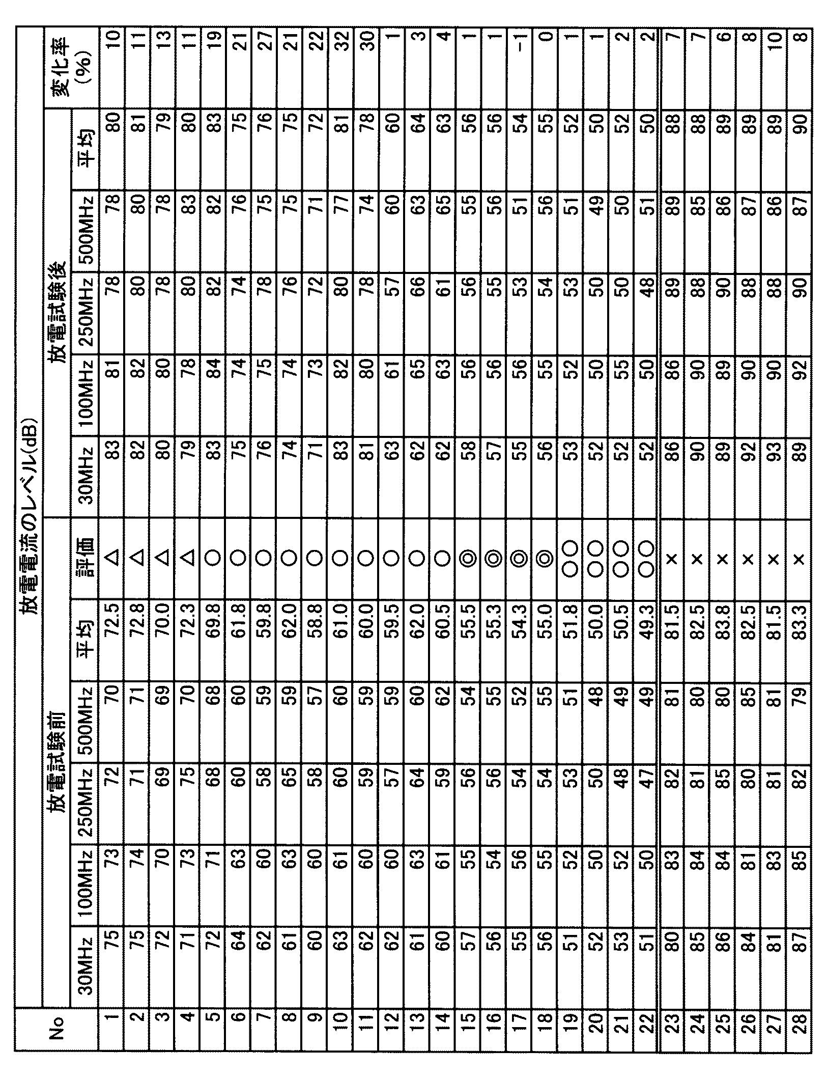
表1及び表2に示す放電試験前の結果をみると、第1層30及び第2層40を備え、且つ、第1粒子32のキュリー温度が第2粒子42のキュリー温度よりも高いサンプル1~22は、第2層40をもたないサンプル23~26、第1粒子32のキュリー温度が第2粒子42のキュリー温度よりも低いサンプル27,28に比べて、放電電流のレベルを小さくすることができた。サンプル1~22は電波ノイズの原因となる高周波数帯の電流のレベルを小さくできるので、電波ノイズを抑制できることが明らかである。
サンプル1~22は、第1層30及び第2層40の軸方向の長さがそれぞれ7mm以上であった。放電電流のレベルを小さくするには、第1層30の軸方向の長さ及び第2層40の軸方向の長さを7mm以上とするのが望ましいことが確認された。
サンプル5~22は、M2+Fe2
3+O4
2-(M2+は2価の金属イオン)の分子式で表されるスピネル型フェライトを第1粒子32及び第2粒子42に用いたサンプルであり、Zn,Cdの両方またはいずれか一方と、Ni,Mn,Cu,Fe,Mg,Coの1種以上の同じ金属イオンと、を第1粒子32及び第2粒子42に含むサンプルである。サンプル5~22は、第2粒子42におけるZn及びCdの総量の割合(mol%)から第1粒子32におけるZn及びCdの総量の割合(mol%)を減じた組成差>0の条件を満たすので、第1粒子32のキュリー温度を第2粒子42のキュリー温度よりも高くできる一方で、第2粒子42のノイズ減衰効果を向上できたと考えられる。その結果、サンプル5~22は、サンプル1~4に比べて、放電電流のレベルを小さくすることができたと推察される。
セラミック相35,45にフェライトを含有するサンプル15~22は、セラミック相35,45にフェライトを含有しないサンプル1~14に比べ、放電電流のレベルを小さくすることができた。サンプル15~22は、セラミック相35,45のフェライトによって、電波ノイズの原因となる高周波数帯の電流のレベルをさらに小さくできるので、電波ノイズの抑制効果をさらに向上できることが明らかである。
また、第1層30及び第2層40の軸方向の全長(最短の長さ)が15mm以上あるサンプル19~22は、放電電流のレベルをさらに小さくできた。従って、サンプル19~22はノイズ減衰効果をさらに向上できることが明らかである。サンプル19~22は、第1層30の軸方向の長さ及び第2層40の軸方向の長さもそれぞれ7mm以上あるので、ノイズ減衰効果を確保できたと推察される。
放電試験前後の変化率によれば、Si,B,Pのうちの少なくとも1種と、アルカリ金属およびアルカリ土類金属のうちの少なくとも1種とをセラミック相35,45に含むサンプル12~22は、変化率が小さく、耐久性に優れることが確認された。
この理由は、サンプル12~22は、Si,B,P等を含むセラミック相35,45がガラス化したからであると推察される。ガラス化して空隙が減少したセラミック相35,45は、スパーク時に空隙で生じる可能性のある放電を抑制できる。その結果、放電によるセラミック相35,45の劣化を抑制できると共に、セラミック相35,45の放電が原因の電波ノイズを抑制できると推察される。
以上、実施の形態に基づき本発明を説明したが、本発明は上記実施の形態に何ら限定されるものではなく、本発明の趣旨を逸脱しない範囲内で種々の改良変形が可能であることは容易に推察できるものである。
上記実施の形態では、第1層30及び第2層40において、セラミック相35,45によって第1磁性粒子31及び第2磁性粒子41が固定化される場合について説明したが、必ずしもこれに限られるものではない。セラミック相35,45を省略して、軸孔12に第1磁性粒子31及び第2磁性粒子41を充填しても、フェライトによる電波ノイズの抑制効果は得られる。従って、セラミック相35,45は当然に省略できる。
上記実施の形態では、スパークプラグ10の製造方法として、第1シール部21、第1層30、第2層40及び第2シール部22の原料粉末を軸孔12に充填した絶縁体11を炉内で加熱する場合を例示したが、必ずしもこれに限られるものではない。例えば、成形型を用いて第1層30及び第2層40の原料粉末を円柱状に成形し、その成形体を焼成して予め第1層30及び第2層40を形成することが可能である。その場合には、第1シール部21の原料粉末、焼成された第1層30及び第2層40、第2シール部22の原料粉末を順に絶縁体11の軸孔12に充填し、絶縁体11を炉内で加熱した状態で端子金具15を軸孔12に圧入して、接続部20を形成する。
上記実施の形態では、中心電極14の先端に接地電極19が対向するスパークプラグ10について説明したが、スパークプラグの構造は必ずしもこれに限られるものではない。スパークプラグの他の構造としては、例えば、中心電極14の側面に接地電極19が対向するスパークプラグ、主体金具17に複数の接地電極19を接合した多極のスパークプラグが挙げられる。
10 スパークプラグ
11 絶縁体 12 軸孔
14 中心電極
15 端子金具
20 接続部
21 第1シール部
22 第2シール部
30 第1層
31 第1磁性粒子
32 第1粒子
33 第1導電性物質
35 セラミック相
40 第2層
41 第2磁性粒子
42 第2粒子
43 第2導電性物質
45 セラミック相
11 絶縁体 12 軸孔
14 中心電極
15 端子金具
20 接続部
21 第1シール部
22 第2シール部
30 第1層
31 第1磁性粒子
32 第1粒子
33 第1導電性物質
35 セラミック相
40 第2層
41 第2磁性粒子
42 第2粒子
43 第2導電性物質
45 セラミック相
Claims (5)
-
先端側から後端側へと軸線の方向に延びる軸孔を有する絶縁体と、
前記軸孔の先端側に少なくとも一部が挿入された中心電極と、
前記軸孔の後端側に少なくとも一部が挿入された端子金具と、
前記端子金具と前記中心電極とを前記軸孔内で接続する接続部と、を備えるスパークプラグであって、
前記接続部は、フェライトの粒子である第1粒子と、前記第1粒子を被覆する第1導電性物質と、をそれぞれ備える複数の第1磁性粒子を含む第1層と、
前記第1層よりも後端側に配置され、前記第1粒子のフェライトよりもキュリー温度が低いフェライトの粒子である第2粒子と、前記第2粒子を被覆する第2導電性物質と、をそれぞれ備える複数の第2磁性粒子を含む第2層と、を備えていることを特徴とするスパークプラグ。 - 前記第1粒子はキュリー温度が300℃以上であり、前記第2粒子はキュリー温度が200℃以上300℃未満であることを特徴とする請求項1記載のスパークプラグ。
- 前記第1層および前記第2層は、前記複数の第1磁性粒子および前記複数の第2磁性粒子の周囲に、ケイ素、ホウ素およびリンのうちの少なくとも1種と、アルカリ金属およびアルカリ土類金属のうちの少なくとも1種とを含むセラミック相を備えていることを特徴とする請求項1又は2に記載のスパークプラグ。
- 前記セラミック相は、前記第1粒子および前記第2粒子とは異なるフェライトを含有していることを特徴とする請求項3記載のスパークプラグ。
- 前記接続部は、前記第1層と前記中心電極とを接続する第1シール部と、
前記第2層と前記端子金具とを接続する第2シール部とを備え、
前記第1層に含まれる前記第1磁性粒子と前記第1シール部とが接する位置から、前記第2層に含まれる前記第2磁性粒子と前記第2シール部とが接する位置までの軸線方向の最短の長さは15mm以上であることを特徴とする請求項1から4のいずれかに記載のスパークプラグ。
Applications Claiming Priority (2)
| Application Number | Priority Date | Filing Date | Title |
|---|---|---|---|
| JP2016-235725 | 2016-12-05 | ||
| JP2016235725A JP6267779B1 (ja) | 2016-12-05 | 2016-12-05 | スパークプラグ |
Publications (1)
| Publication Number | Publication Date |
|---|---|
| WO2018105361A1 true WO2018105361A1 (ja) | 2018-06-14 |
Family
ID=61020827
Family Applications (1)
| Application Number | Title | Priority Date | Filing Date |
|---|---|---|---|
| PCT/JP2017/041482 Ceased WO2018105361A1 (ja) | 2016-12-05 | 2017-11-17 | スパークプラグ |
Country Status (2)
| Country | Link |
|---|---|
| JP (1) | JP6267779B1 (ja) |
| WO (1) | WO2018105361A1 (ja) |
Citations (2)
| Publication number | Priority date | Publication date | Assignee | Title |
|---|---|---|---|---|
| JPS54158541A (en) * | 1978-06-02 | 1979-12-14 | Nippon Denso Co Ltd | Ignition plug with resistive substance |
| JPS5686475A (en) * | 1979-12-18 | 1981-07-14 | Ngk Spark Plug Co | Ignition plug with ceramic electrode |
-
2016
- 2016-12-05 JP JP2016235725A patent/JP6267779B1/ja not_active Expired - Fee Related
-
2017
- 2017-11-17 WO PCT/JP2017/041482 patent/WO2018105361A1/ja not_active Ceased
Patent Citations (2)
| Publication number | Priority date | Publication date | Assignee | Title |
|---|---|---|---|---|
| JPS54158541A (en) * | 1978-06-02 | 1979-12-14 | Nippon Denso Co Ltd | Ignition plug with resistive substance |
| JPS5686475A (en) * | 1979-12-18 | 1981-07-14 | Ngk Spark Plug Co | Ignition plug with ceramic electrode |
Also Published As
| Publication number | Publication date |
|---|---|
| JP2018092807A (ja) | 2018-06-14 |
| JP6267779B1 (ja) | 2018-01-24 |
Similar Documents
| Publication | Publication Date | Title |
|---|---|---|
| JP6026022B2 (ja) | スパークプラグ | |
| JP5902757B2 (ja) | スパークプラグ | |
| JP5996044B1 (ja) | スパークプラグ | |
| JP6246063B2 (ja) | スパークプラグ | |
| JP5931955B2 (ja) | スパークプラグ | |
| JP5925839B2 (ja) | スパークプラグ | |
| JP6267779B1 (ja) | スパークプラグ | |
| WO2018105292A1 (ja) | スパークプラグ | |
| JP6606136B2 (ja) | スパークプラグ | |
| JP6548701B2 (ja) | スパークプラグ | |
| JP2017062879A (ja) | スパークプラグ | |
| JP6997679B2 (ja) | スパークプラグ | |
| JP2019091646A (ja) | スパークプラグ | |
| JP7028720B2 (ja) | スパークプラグ | |
| JP6855330B2 (ja) | スパークプラグ | |
| WO2018079089A1 (ja) | 点火プラグ | |
| JP6294982B2 (ja) | スパークプラグ | |
| JP2017201576A (ja) | スパークプラグ | |
| JP2016009568A (ja) | スパークプラグ |
Legal Events
| Date | Code | Title | Description |
|---|---|---|---|
| 121 | Ep: the epo has been informed by wipo that ep was designated in this application |
Ref document number: 17879388 Country of ref document: EP Kind code of ref document: A1 |
|
| NENP | Non-entry into the national phase |
Ref country code: DE |
|
| 122 | Ep: pct application non-entry in european phase |
Ref document number: 17879388 Country of ref document: EP Kind code of ref document: A1 |