WO2018105232A1 - 風車制御装置 - Google Patents
風車制御装置 Download PDFInfo
- Publication number
- WO2018105232A1 WO2018105232A1 PCT/JP2017/036957 JP2017036957W WO2018105232A1 WO 2018105232 A1 WO2018105232 A1 WO 2018105232A1 JP 2017036957 W JP2017036957 W JP 2017036957W WO 2018105232 A1 WO2018105232 A1 WO 2018105232A1
- Authority
- WO
- WIPO (PCT)
- Prior art keywords
- wind speed
- control
- rotation
- wind
- level
- Prior art date
- Legal status (The legal status is an assumption and is not a legal conclusion. Google has not performed a legal analysis and makes no representation as to the accuracy of the status listed.)
- Ceased
Links
Images




Classifications
-
- F—MECHANICAL ENGINEERING; LIGHTING; HEATING; WEAPONS; BLASTING
- F03—MACHINES OR ENGINES FOR LIQUIDS; WIND, SPRING, OR WEIGHT MOTORS; PRODUCING MECHANICAL POWER OR A REACTIVE PROPULSIVE THRUST, NOT OTHERWISE PROVIDED FOR
- F03D—WIND MOTORS
- F03D7/00—Controlling wind motors
- F03D7/02—Controlling wind motors the wind motors having rotation axis substantially parallel to the air flow entering the rotor
- F03D7/04—Automatic control; Regulation
-
- Y—GENERAL TAGGING OF NEW TECHNOLOGICAL DEVELOPMENTS; GENERAL TAGGING OF CROSS-SECTIONAL TECHNOLOGIES SPANNING OVER SEVERAL SECTIONS OF THE IPC; TECHNICAL SUBJECTS COVERED BY FORMER USPC CROSS-REFERENCE ART COLLECTIONS [XRACs] AND DIGESTS
- Y02—TECHNOLOGIES OR APPLICATIONS FOR MITIGATION OR ADAPTATION AGAINST CLIMATE CHANGE
- Y02E—REDUCTION OF GREENHOUSE GAS [GHG] EMISSIONS, RELATED TO ENERGY GENERATION, TRANSMISSION OR DISTRIBUTION
- Y02E10/00—Energy generation through renewable energy sources
- Y02E10/70—Wind energy
- Y02E10/72—Wind turbines with rotation axis in wind direction
Definitions
- Patent Document 1 discloses a technique aimed at preventing over-rotation of a wind turbine for wind power generation.
- the torque command circuit disclosed in Patent Document 1 includes means for integrating the deviation between the actual rotational speed of the wind power generator and the rated rotational speed to output an overspeed integrated amount, and an overwind speed from the overspeed integrated amount.
- This torque command circuit controls the torque of the generator by the torque command value at the time of rotational speed control when the overwind speed state signal is ON to prevent overspeed of the windmill.
- control is performed so that a deceleration command is output when the integrated deviation value of the generator rotational speed and the rated rotational speed exceeds a certain value.
- the rotational speed reduction amount at this time is determined based on a value obtained by dividing the deviation integrated value of the generator rotational speed and the rated rotational speed by the integrated time. That is, in this control, when the wind speed is high, the deviation integrated value exceeds a certain value in a short integrated time, and therefore the amount of deceleration becomes larger. Conversely, when the wind speed continues at a level slightly exceeding the rated wind speed, the amount of deceleration is small.
- the control unit When the wind speed measured by the wind speed sensor is maintained at a wind speed level lower than the current level before the change for a certain period of time or longer during execution of the rotation suppression mode control, the control unit is more predetermined than the rotation speed level being controlled.
- the descent countermeasure control for controlling the rotational speed of the wind turbine so as to target a large rotational speed level within the limit number of the above may be executed.
- This windmill control device increases the rotational speed level within a predetermined limit number of steps on condition that the state in which the wind speed has decreased by one or more steps is stably maintained for a certain period of time or more. It is possible to increase the rotation level step by step with emphasis on prudentity while confirming a low state.
- the rotation suppression mode control when executed, the rotation speed is reduced to the maximum rotation speed level, and the wind speed is less than a predetermined value and is not maintained for a predetermined time or more, so the control does not switch to the normal mode control. It is possible to switch to the normal mode only when the wind speed is stably low.
- the windmill 100 shown in FIGS. 1 and 2 is configured as a vertical axis type windmill, for example, and a straight blade vertical axis windmill in which a plurality of straight blades are connected so as to be integrally rotatable around a rotating shaft extending in the vertical direction. It is constituted by.
- the wind turbine 100 includes a plurality of wing portions 104 extending in a predetermined direction (vertical direction that is the axial direction of the rotation shaft portion 102), and a rotation shaft portion 102 configured in a rod shape and extending in a predetermined direction.
- the wind turbine control device 2 includes a control unit 10, a rectification / boost unit 50, a rotation suppression unit 20, a second electric brake unit 30, a step-down unit 40, detection units 91 and 92, a rotation speed sensor 7, a wind speed. It is comprised by the sensor 9, each wiring part, etc., and functions as an apparatus which controls the rotation of the windmill 100 while controlling the output electric power from the generator 3.
- FIG. 10 the control unit 10
- a rectification / boost unit 50 the wind turbine control device 2
- a rotation suppression unit 20 As shown in FIG. 1, the wind turbine control device 2 includes a control unit 10, a rectification / boost unit 50, a rotation suppression unit 20, a second electric brake unit 30, a step-down unit 40, detection units 91 and 92, a rotation speed sensor 7, a wind speed. It is comprised by the sensor 9, each wiring part, etc., and functions as an apparatus which controls the rotation of the windmill 100 while controlling the output electric power from the generator 3.
- FIG. 10 the control unit 10
- Rotation suppression unit 20 is a part that performs a suppression operation (deceleration operation that decelerates the rotation speed) that suppresses rotation of windmill 100 and cancels the suppression operation.
- the rotation suppression unit 20 includes a first electric brake unit 21 and a mechanical brake unit 22.
- the mechanical brake unit 22 corresponds to an example of a second brake unit, and is a device that can perform a braking operation on the windmill 100.
- the mechanical brake unit 22 includes a brake operation unit 24 and a drive circuit 26.
- the brake operation unit 24 is configured as, for example, a reverse-acting pneumatic brake, and a pair of contact members 24B that act on the operated portion 106 that is configured as a part of the windmill 100, and an actuator that drives the contact members 24B. (Actuator) 24A.
- the actuated portion 106 is configured, for example, as a disk-shaped disk integrally assembled with the rotating shaft portion 102 of the windmill 100, and rotates integrally with the plurality of wing portions 104 provided in the windmill 100.
- the first electric brake unit 21 corresponds to an example of the first brake unit, and is configured as a circuit that can perform electrical control on the generator 3.
- the first electric brake unit 21 is a circuit that can perform a first brake operation that generates a force against the rotational force of the windmill 100 in the generator 3 and a release of the first brake operation.
- 4 is configured as a circuit as shown in FIG.
- the branch path 21 ⁇ / b> A is branched from the path that continues to the rectifier / boost unit 50 side.
- 21B, 21C are provided.
- resistance portions R1, R2, and R3 are interposed in the branch paths 21A, 21B, and 21C, respectively.
- the branch paths 21A, 21B, and 21C are connected to each other by a connection path 21D.
- branch paths 21A, 21B, and 21C when a current flows from one of the branch paths to the other branch path, a current flows through the resistor, and a voltage drop occurs in the resistor.
- the branch paths 21B and 21C are provided with switches SW1 and SW2 for switching between an energizable state and an energized cut-off state, respectively, and the on / off state of the switches SW1 and SW2 is controlled by the control unit 10.
- the control unit 10 performs control to turn on the switches SW1 and SW2 when performing a first brake operation described later, and performs control to turn off the switches SW1 and SW2 when not performing the first brake operation.
- a resistor 34 and a switch element 32 are connected in series between the conductive path 71 and the conductive path 72, and a current flows through the resistor 34 in response to an ON operation of the switch element 32, thereby rectifying and boosting the unit. It functions to consume part of the power output from 50.
- a PWM (Pulse Width Modulation) signal output from the drive unit 15 is input to the gate of the switch element 32, and the power consumption in the second electric brake unit 30 is controlled by the duty of the PWM signal.
- the capacitor 55 is connected between the conductive path 71 and the conductive path 72.
- the capacitor 55 has a function of smoothing the input current input to the step-down unit 40.
- the step-down unit 40 is configured as a known step-down converter (converter), and includes a switch element 42 that turns on and off the conduction path 71, a diode 44, a coil 48, and a capacitor 46.
- the switch element 42 is configured by a MOSFET or the like, for example, and is configured to be turned on / off according to the PWM signal from the drive unit 16.
- the battery 60 is configured as, for example, a known secondary battery, and functions as a power source for driving various loads constituting the wind power generation system 1.
- the wind power generation system 1 is provided with a power supply circuit that generates a plurality of power supply voltages based on the power from the battery 60.
- the control unit 10 is generated by the power supply circuit.
- a power supply voltage is applied.
- a switch 61 is provided between the positive terminal of the battery 60 and the output-side conductive path 81, and on / off of the switch 61 is controlled by the control unit 10.
- Rotational speed sensor 7 corresponds to an example of a detection unit that detects the rotational speed of windmill 100.
- the rotational speed sensor 7 may be any sensor that can detect the rotational speed of the rotating shaft portion 102 of the windmill 100, and various known rotational speed sensors can be used.
- the control unit 10 acquires the output value from the rotation speed sensor 7 and grasps the rotation speed of the windmill 100.
- the wind speed sensor 9 is configured by a known wind speed sensor and functions to measure the wind speed in the vicinity of the wind turbine 100.
- the wind speed sensor 9 is attached to a predetermined position (for example, a part other than the rotor blades) of the windmill 100, and outputs a value indicating the wind speed at the position where the wind speed sensor 9 is attached.
- the control unit 10 acquires an output value (detected value) from the wind speed sensor 9 and grasps the wind speed near the windmill.
- the control unit 10 includes, for example, a control circuit 12 composed of a microcomputer, a storage unit 18 composed of ROM, RAM, etc., and a plurality of drive units 14, 15, 16 that output control signals. .
- various detection values are input to the control unit 10.
- the detection unit 91 illustrated in FIG. 1 includes a current sensor and a voltage sensor, and an output current and an output voltage output from the rectification / boost unit 50 are detected by the detection unit 91 and input to the control unit 10.
- the detection unit 92 includes a current sensor and a voltage sensor, and the output current and output voltage output from the step-down unit 40 are detected by the detection unit 92 and input to the control unit 10.
- the output terminal 62 of the wind power generation system 1 can be connected to the input terminal 122 of the storage battery system 120, for example. That is, the electric power generated in the wind power generation system 1 can be supplied to the external storage battery system 120 via the output terminal 62.
- FIGS. 1 and 2 an example in which the electric power generated in the wind power generation system 1 is supplied to the storage battery system 120 is shown. However, a configuration for grid connection is added and connected to a commercial power supply system. Also good.
- the wind power generation system 1 configured as described above converts the electric power obtained by the power generation of the generator 3 and outputs it when the windmill 100 is rotated by receiving wind power and the control unit 10 is performing power generation control. To do. However, when the wind speed detected by the wind speed sensor 9 exceeds a predetermined threshold value, the rotation suppression mode control or the rotation stop control described later is performed, and the rotation of the windmill 100 is decelerated or stopped.
- the control unit 10 controls the normal mode in which the rotation suppression unit 20 is in a predetermined operation release state with the flow illustrated in FIG. 5 and the rotation that rotates the windmill 100 while operating the rotation suppression unit 20.
- the control of the suppression mode and the control of the stop mode for stopping the windmill 100 are performed.
- the control unit 10 determines that the wind speed measured by the wind speed sensor 9 is The rotation suppression mode control is performed so that the associating control is performed to decrease the rotational speed of the windmill 100 as the wind speed increases when the wind speed increases.
- the control unit 10 when the predetermined operation start condition is satisfied (for example, the rotational speed of the windmill 100 detected by the rotational speed sensor 7 is equal to or higher than the predetermined power generation start rotational speed, the control unit 10 performs a rotation suppression mode and a rotation stop described later.
- the mode is not set, the wind turbine control shown in FIG. 5 is started.
- the control unit 10 first starts the normal mode control at step S1. After starting the control in the normal mode, the control unit 10 detects in step S2 the condition that the wind speed measured by the wind speed sensor 9 is equal to or higher than the first wind speed threshold value (predetermined value) Vw1, or the rotational speed sensor 7.
- step S2 it is determined whether or not a condition that the rotation speed is equal to or higher than the first rotation speed threshold value Vr1 is satisfied.
- the wind speed measured by the wind speed sensor 9 is less than the first wind speed threshold value (predetermined value) Vw1, and the rotation speed detected by the rotation speed sensor 7 is less than the first rotation speed threshold value Vr1.
- the determination of No in step S2 is repeated, and during this period, the power generation control in the normal mode is continued.
- control unit 10 When performing power generation control in the normal mode, the control unit 10 outputs a control signal to each of the switch elements Sa1, Sb1, Sa2, Sb2, Sa3, Sb3, and operates the rectification / boost unit 50 as a three-phase boost chopper circuit. .
- the rotation speed (number of rotations) and the output target value (generator regeneration output) are associated in advance, and the correspondence data in which the rotation speed and the output target value are associated in this way is stored in the storage unit 18. Is remembered. Since such correspondence data exists, if the rotational speed is determined by the rotational speed sensor 7, the output target value (generator regenerative output) associated with the rotational speed (number of revolutions) is determined with reference to the correspondence data. be able to.
- Each output target value corresponding to each rotation speed is the maximum power value at each rotation speed, and is set to be proportional to the cube of the rotation speed (the number of rotations).
- the control unit 10 determines the rotational speed (number of rotations) of the windmill 100 detected by the rotational speed sensor 7 and the rotational speed stored in the storage unit 18.
- Output target value maximum power value corresponding to each rotation speed
- the output power from the rectifying / boosting unit 50 is an output target value (maximum power value) corresponding to the rotation speed (rotation speed) of the windmill 100.
- MPPT Maximum Power Point Tracking
- the control of FIG. 5 is temporarily performed.
- the operation may be stopped until the operation start condition is satisfied.
- the control shown in FIG. 5 may be executed again when the operation start condition is satisfied.
- the control unit 10 repeats the determination in step S2 during the execution of the normal mode, and when the wind speed measured by the wind speed sensor 9 becomes equal to or higher than the first wind speed threshold value (predetermined value) Vw1, or detected by the rotational speed sensor 7.
- the control is switched to the rotation suppression mode control in step S3.
- the control unit 10 performs control according to the table data (table data) as shown in FIG. 6 when the control is switched to the rotation suppression mode control from step S2 to step S3.
- the table data of FIG. 6 defines a plurality of stages of wind speed levels and a plurality of stages of rotation speed levels in a wind speed range that is greater than or equal to the first wind speed threshold Vw1 (predetermined value) and less than the second wind speed threshold Vw2, and rotates as the wind speed level increases. This is correspondence data in which the wind speed level and the rotation speed level are associated with each other so that the speed level becomes small.
- This table data (corresponding data) is stored in the storage unit 18. In the table data of FIG. 6, the larger the table number, the smaller the associated wind speed level (wind speed range) and the greater the associated rotational speed level.
- the first wind speed threshold value Vw1 is 11 (m / s), and the second wind speed threshold value Vw2 is 22 (m / s).
- table number 6 is associated with a wind speed level of 11 (m / s) or more and less than 12 (m / s) and a rotational speed level of 180 (min ⁇ 1)
- table number 5 is 12 (m / s).
- / S) is associated with a wind speed level of 13 (m / s) or more and a rotational speed level of 170 (min-1)
- the table number 4 is 13 (m / s) or more and less than 14 (m / s). Is associated with a rotational speed level of 160 (min-1), and Table No.
- Table number 3 has a wind speed level of 14 (m / s) to less than 16 (m / s) and 150 (min-1). Rotational speed levels are associated with each other.
- Table number 2 is associated with a wind speed level of 16 (m / s) or more and less than 18 (m / s) and a rotational speed level of 140 (min ⁇ 1). 18 (m / s) or more A wind speed level of less than 0 (m / s) and a rotational speed level of 120 (min-1) are associated with each other.
- Table number 0 includes a wind speed level of 20 (m / s) or more and less than 22 (m / s) and A rotational speed level of 100 (min-1) is associated.
- step S5 when the wind speed becomes equal to or higher than the second wind speed threshold value Vw2 when the rotation suppression mode control is being performed (Yes in step S4), the process proceeds to step S6 to switch to the stop mode control. Further, when a predetermined return condition is satisfied when the rotation suppression mode control is performed (Yes in step S5), the process proceeds to step S1 to switch to the normal mode control.
- the control unit 10 uses the table data shown in FIG. 6 to set the wind speed level measured by the wind speed sensor 9 in the corresponding data when the wind speed measured by the wind speed sensor 9 rises.
- the wind speed measured by the wind speed sensor 9 is executed by performing ascending correspondence control for controlling the rotational speed of the windmill 100 so as to target the associated rotational speed level or a level shifted from the associated rotational speed level by a predetermined step.
- the descent response control is executed so that the rotation speed of the wind turbine 100 is increased by the number of steps within a predetermined limit number based on the plurality of rotation speed levels in the response data.
- the predetermined limit number is “2”
- step S2 to step S3 that is, immediately after the wind speed is equal to or higher than the first wind speed threshold (predetermined value) Vw1 or the rotational speed of the windmill 100 is equal to or higher than the first rotational speed threshold Vr1).
- the highest table number with the highest number is selected.
- the control unit 10 monitors the wind speed measured by the wind speed sensor 9 and the rotational speed detected by the rotational speed sensor 7, and a new wind speed in which the wind speed measured by the wind speed sensor 9 is higher than the current level before the change.
- the rotational speed of the windmill is controlled so as to target a level shifted from the rotational speed level associated with the new wind speed level by the corresponding data by a predetermined step.
- step S2 to step S3 For example, if the wind speed immediately after the transition from step S2 to step S3 is 11 (m / s), that is, the current speed before the change corresponds to the table number 6 (current table number) (11 (m / S) to 12 (m / s)), the wind speed then becomes 14 (m / s), so that a new wind speed level higher than the current level before the change (corresponding to table number 3).
- Table number 3 (corresponding to the new wind speed level (14 (m / s) to 16 (m / s)) when the wind speed level (14 (m / s) to 16 (m / s)) is changed.
- the rotational speed of the wind turbine is set so as to target the rotational speed level (140 min-1) shifted by one step from the rotational speed level (150 min-1) associated with the correspondence data shown in FIG. Control That.
- the example shown here is merely an example, and when the wind speed level to be measured is switched to be increased by one level or more during execution of the rotation suppression mode, it is associated with the wind speed level after switching.
- the rotational speed is controlled by one step lower than the rotational speed.
- the control unit 10 maintains the wind speed measured by the wind speed sensor 9 below a wind speed level lower than the current level before the change for a certain time (for example, 5 seconds) or more.
- the descent response control for controlling the rotational speed of the windmill so as to target a rotational speed level that is larger than the rotational speed level being controlled within a predetermined limit number of steps is executed.
- the predetermined number of limit steps is “2”, and even if the state in which the wind speed is greatly reduced is maintained, the level of the rotation speed is not switched more than two steps at a time.
- the wind speed at a certain time is 16 m / s
- the current level before the change is the wind speed level (16 (m / s) to 18 (m / s)) corresponding to table number 2 (current table number).
- the wind speed is 12 (m / s) thereafter.
- the wind speed level changes to a new wind speed level (wind speed level (12 (m / s) to 13 (m / s)) corresponding to the table number 5) that is smaller than the current level before the change.
- the rotational speed of the wind turbine is controlled so as to target (150 min-1), that is, the target rotational speed is changed from the rotational speed level before the change (120 min-1) to only “2 stages” which is the limit number of stages.
- the wind turbine 100 is controlled at this new rotational speed by switching to the increased (150 min-1).
- control unit 10 performs the most in a plurality of wind speed levels (FIG. 6) in a wind speed range of a predetermined value (11 (m / s) which is the first wind speed threshold Vw1) or more during execution of the rotation suppression mode control.
- the maximum rotational speed level (that is, the figure) corresponding to the small wind speed level (that is, the wind speed level 11 to 12 (m / s) corresponding to the highest table number 6) in the corresponding data (FIG. 6).
- the wind speed measured by the wind speed sensor 9 is 11 (m / s) which is the predetermined value (the first wind speed threshold Vw1).
- step S5 in FIG. 5 is Yes, and control in the normal mode is executed in step S1.
- step S6 stop mode control is executed.
- the control in the stop mode for example, the rotation of the windmill 100 is stopped by operating the first electric brake unit 21 and the mechanical brake unit 22 described above until the rotational speed of the windmill 100 becomes zero. And the windmill 100 is maintained in a rotation stop state until a predetermined release condition is satisfied.
- the release condition can be set in various ways, for example, “the wind speed measured by the wind speed sensor 9 is maintained below a predetermined release determination threshold value for a predetermined time or more”.
- the predetermined release determination threshold may be the second wind speed threshold Vw2, or may be a value smaller than the second wind speed threshold Vw2.
- the control unit 10 increases the wind speed measured by at least the wind speed sensor 9 when the wind speed measured by the wind speed sensor 9 is equal to or higher than the predetermined value Vw1 during the normal mode control.
- the rotation suppression mode is controlled so as to execute the ascending response control in which the rotation speed of the windmill 100 is decreased as the wind speed increases.
- the rotation suppression mode is controlled when the wind speed measured by the wind speed sensor 9 is equal to or higher than the predetermined value Vw1
- the rotational speed is greatly increased. It becomes easy to perform rotation suppression operation quickly before.
- the associative control is executed so as to decrease the rotation speed of the windmill 100 as the wind speed increases, so that the more the wind speed situation where the possibility of over-rotation increases, the more the situation is reflected.
- the degree of rotation suppression can be strengthened.
- the wind turbine control device 2 determines a plurality of stages of wind speed levels and a plurality of stages of rotation speed levels in a wind speed range of at least a predetermined value Vw1 or more, and increases the wind speed level and rotation speed level so that the rotation speed level decreases as the wind speed level increases.
- a storage unit 18 that stores correspondence data that associates.
- Ascending response control for controlling the rotational speed of the wind turbine 100 so as to target a level shifted by a step is executed, and when the wind speed measured by the wind speed sensor 9 decreases, a plurality of stages in the corresponding data
- the descent response control is executed so that the rotational speed of the wind turbine 100 is increased by the number of steps within a predetermined limit number based on the rotational speed level.
- the windmill control device 2 changes a level shifted by a predetermined step from the rotation speed level associated with the wind speed level measured by the wind speed sensor 9 in the corresponding data when the wind speed increases. Since the associative control for controlling the rotational speed of the windmill 100 so as to be a target is executed, it is possible to immediately switch to the rotational speed corresponding to the wind speed when the wind speed increases. Therefore, it becomes easy to prevent the occurrence of over-rotation due to a sudden rise in the wind speed.
- the descent response control is executed so that the rotation speed of the windmill 100 is increased by the number of stages within a predetermined limit number based on the rotation speed levels in a plurality of stages in the correspondence data.
- the rotation speed can be returned little by little under the circumstances. For example, even if a situation occurs in which the wind speed suddenly drops and then rises rapidly, the rotational speed does not increase so much when the wind speed suddenly drops. Become.
- the control unit 10 uses the corresponding data for the new wind speed level.
- the rotational speed of the wind turbine is controlled so as to target a level shifted from the associated rotational speed level by a predetermined step.
- the wind turbine control device 2 When the wind speed level measured by the wind speed sensor 9 is increased by one or more levels during execution of the rotation suppression mode control, the wind turbine control device 2 reduces the rotational speed of the wind turbine 100 according to the increased wind speed level. It is possible to quickly switch to the rotational speed level.
- the control unit 10 determines from the rotation speed level being controlled. Also, the descent response control is executed to control the rotational speed of the windmill so as to target a large rotational speed level within a predetermined limit number of steps.
- the wind turbine control device 2 increases the rotational speed level within a predetermined number of limit steps on the condition that the state in which the wind speed has decreased by one or more steps is stably maintained for a certain time or more, the wind speed can increase rapidly. It is possible to increase the rotation level step by step with emphasis on prudence while reliably confirming a low-priced state.
- the control unit 10 targets the highest rotational speed level associated with the lowest wind speed level in the plurality of stages in the wind speed range equal to or greater than a predetermined value in the correspondence data.
- the rotational speed of the windmill 100 When the rotational speed of the windmill 100 is controlled as described above, it functions to switch to normal mode control on condition that the wind speed measured by the wind speed sensor 9 is less than a predetermined value and maintained for a predetermined time or more.
- the windmill control device 2 When the rotation suppression mode control is executed, the windmill control device 2 is not switched to the normal mode control unless the rotation speed is lowered to the maximum rotation speed level and the wind speed is maintained below a predetermined value for a predetermined time or more. Therefore, it is possible to switch to the normal mode only when the wind speed is stably low.
- a mechanical brake as disclosed in JP 2011-256723 A may be used.
- cooperating with this is not limited to the position of the to-be-acted part 106 of Example 1.
- a contact member (a member driven by an actuator) of the mechanical brake unit 22 is an interlocking member that interlocks with the windmill 100 (for example, a member that interlocks with the windmill 100 by gear transmission or the like).
- the second brake operation may be performed so as to generate a braking force while bringing the contact member into contact with the (acting portion).
- an example of the first electric brake unit 21 (first brake unit) is shown in FIG.
- the first brake unit generates a braking force in the rotation of the generator by electrical control.
- Various known electric brakes can be used as long as they can be configured.
- resistance part R1, R2, R3 was used, you may make it short-circuit by omitting these.
- the lower level (rotation speed) shifted by one step from the rotation speed associated with the increased wind speed is targeted.
- the target rotational speed is switched, the present invention is not limited to this example.
- the target rotational speed is shifted to a lower level (rotational speed) shifted by two stages from the rotational speed associated with the increased wind speed.
- the “predetermined limit number” and the “limit stage number” are set to 2, and when the wind speed is lowered and stabilized, the rotational speed level is decreased stepwise within two stages. You may make it fall one step at a time.
- table data as conceptually illustrated in FIG. 6 is illustrated as an example of the correspondence data, but FIG. 6 is merely an example of the correspondence data.
- the table configuration is not limited to the table configuration as shown in FIG. 6, and may be a table configuration in which the wind speed range is divided more finely and the rotation speed is associated with each wind speed range. May be roughly divided.
- the rotational speed corresponding to the wind speed level is determined by an arithmetic expression that associates the wind speed level and the rotational speed level so that the rotational speed level decreases as the wind speed level increases. You may make it do.
Landscapes
- Engineering & Computer Science (AREA)
- Life Sciences & Earth Sciences (AREA)
- Sustainable Development (AREA)
- Sustainable Energy (AREA)
- Chemical & Material Sciences (AREA)
- Combustion & Propulsion (AREA)
- Mechanical Engineering (AREA)
- General Engineering & Computer Science (AREA)
- Wind Motors (AREA)
Abstract
風速が急に上昇する場合でも風速上昇に迅速に反応して風速に応じた回転抑制制御を行い得る風力発電用の風車制御装置を提供する。 風車制御装置(2)は、風車(100)の回転を抑制する回転抑制部(20)と、風車(100)の回転速度を検出する回転速度センサ(7)(検出部)と、回転抑制部(20)を所定の動作解除状態とする通常モードの制御と、回転抑制部(20)を動作させつつ風車(100)を回転させる回転抑制モードの制御とを少なくとも行う制御部(10)とを有する。制御部(10)は、通常モードの制御を行っているときに風速センサ(9)で計測される風速が所定値以上になった場合、少なくとも風速センサ(9)で計測される風速が上昇する風速上昇時に風速が大きいほど風車(100)の回転速度を小さくする上昇対応制御を実行するように回転抑制モードの制御を行う。
Description
本発明は、風力発電用の風車制御装置に関するものである。
特許文献1には、風力発電用の風車の過回転を防止することを目的とした技術が開示されている。特許文献1で開示されるトルク(torque)指令回路は、風力発電機の実回転数と定格回転数との偏差を積分して過速度積算量を出力する手段と、過速度積算量より過風速状態信号を出力する手段と、過風速状態信号と過速度積算量より風車回転数指令を出力する手段と、風車回転数指令と実回転数より回転数制御時トルク指令値を出力する手段とを備える。このトルク指令回路は、過風速状態信号がONの時に回転数制御時トルク指令値により発電機のトルクを制御して風車の過速度を防止する。
特許文献1のトルク指令回路では、発電機の回転数と定格回転数との偏差積算値が一定値を超えると減速指令を出力するように制御を行う。このときの回転数減速量は、発電機回転数と定格回転数の偏差積算値を積算時間で割った値に基づいて定められる。つまり、この制御では、風速が大きい場合には短い積算時間で偏差積算値が一定値を超えるため、より大きな減速量となる。逆に、風速が定格風速を少し超える程度で継続する場合、小さな減速量となる。
しかし、特許文献1の制御では、風速の上昇が回転速度の上昇に反映された後で減速制御に移行するため、風速の変化から減速制御に移行するまでにタイムラグ(time lag)が生じやすい。このため、風速が急激に変化するような突風傾向にある場合、減速制御が間に合わずに過回転を招く虞がある。
本発明は、上述した実情に鑑みてなされたものであり、風速が急に上昇する場合でも風速上昇に迅速に反応して風速に応じた回転抑制制御を行い得る風車制御装置を提供することを解決すべき課題としている。
本発明は、
風車の回転力を変換して電力を生じさせる発電機と、風速を計測する風速センサと、を備えた風力発電システムにおいて前記風車を制御する風車制御装置であって、
前記風車の回転を抑制する回転抑制部と、
前記風車の回転速度を検出する検出部と、
前記回転抑制部を所定の動作解除状態とする通常モードの制御と、前記回転抑制部を動作させつつ前記風車を回転させる回転抑制モードの制御とを少なくとも行う制御部と、
を有し、
前記制御部は、前記通常モードの制御を行っているときに前記風速センサで計測される風速が所定値以上になった場合、少なくとも前記風速センサで計測される風速が上昇する風速上昇時に風速が大きいほど前記風車の回転速度を小さくする上昇対応制御を実行するように前記回転抑制モードの制御を行う。
風車の回転力を変換して電力を生じさせる発電機と、風速を計測する風速センサと、を備えた風力発電システムにおいて前記風車を制御する風車制御装置であって、
前記風車の回転を抑制する回転抑制部と、
前記風車の回転速度を検出する検出部と、
前記回転抑制部を所定の動作解除状態とする通常モードの制御と、前記回転抑制部を動作させつつ前記風車を回転させる回転抑制モードの制御とを少なくとも行う制御部と、
を有し、
前記制御部は、前記通常モードの制御を行っているときに前記風速センサで計測される風速が所定値以上になった場合、少なくとも前記風速センサで計測される風速が上昇する風速上昇時に風速が大きいほど前記風車の回転速度を小さくする上昇対応制御を実行するように前記回転抑制モードの制御を行う。
本発明に係る風車制御装置において、制御部は、通常モード(mode)の制御を行っているときに風速センサ(sensor)で計測される風速が所定値以上になった場合、少なくとも風速センサで計測される風速が上昇する風速上昇時に風速が大きいほど風車の回転速度を小さくする上昇対応制御を実行するように回転抑制モードの制御を行う。このように風速センサで計測される風速が所定値以上になった場合に回転抑制モードの制御を行うため、風速が急上昇して所定値以上となった場合、回転速度が大きく上昇する前に迅速に回転抑制動作が行われやすくなる。更に、回転抑制モードでは、風速上昇時に風速が大きいほど風車の回転速度を小さくするように上昇対応制御を実行するため、過回転が生じる可能性が大きくなる風速状況であるほどその状況を反映して回転抑制度合いを強めることができる。
本発明における好ましい実施の形態を説明する。
本発明は、少なくとも所定値以上の風速範囲における複数段階の風速レベル(level)と複数段階の回転速度レベルとを定めるとともに風速レベルが大きいほど回転速度レベルが小さくなるように風速レベルと回転速度レベルとを対応付けた対応データを記憶する記憶部を有していてもよい。制御部は、回転抑制モードの制御を行う場合、風速センサで計測される風速が上昇する風速上昇時には対応データにおいて風速センサで計測される風速レベルに対応付けられた回転速度レベル又は対応付けられた回転速度レベルから所定段階シフト(shift)したレベルを目標とするように風車の回転速度を制御する上昇対応制御を実行し、風速センサで計測される風速が下降する風速下降時には対応データにおける複数段階の回転速度レベルに基づいて風車の回転速度を所定制限数以内の段階数ずつ大きくするように下降対応制御を実行してもよい。
本発明は、少なくとも所定値以上の風速範囲における複数段階の風速レベル(level)と複数段階の回転速度レベルとを定めるとともに風速レベルが大きいほど回転速度レベルが小さくなるように風速レベルと回転速度レベルとを対応付けた対応データを記憶する記憶部を有していてもよい。制御部は、回転抑制モードの制御を行う場合、風速センサで計測される風速が上昇する風速上昇時には対応データにおいて風速センサで計測される風速レベルに対応付けられた回転速度レベル又は対応付けられた回転速度レベルから所定段階シフト(shift)したレベルを目標とするように風車の回転速度を制御する上昇対応制御を実行し、風速センサで計測される風速が下降する風速下降時には対応データにおける複数段階の回転速度レベルに基づいて風車の回転速度を所定制限数以内の段階数ずつ大きくするように下降対応制御を実行してもよい。
この風車制御装置は、制御部が回転抑制モードの制御を行う場合、風速センサで計測される風速が上昇する風速上昇時には対応データにおいて風速センサで計測される風速レベルに対応付けられた回転速度レベル又は対応付けられた回転速度レベルから所定段階シフトしたレベルを目標とするように風車の回転速度を制御する上昇対応制御を実行する。つまり、風速上昇時には風速に応じた回転速度に即座に切り替えることができるため、風速の急上昇に起因する過回転の発生を防ぎやすくなる。一方、回転抑制モードの制御を行う場合において風速センサで計測される風速が下降する風速下降時には、対応データにおける複数段階の回転速度レベルに基づいて風車の回転速度を所定制限数以内の段階数ずつ大きくするように下降対応制御を実行する。つまり、風速が低く安定している状況下で少しずつ回転速度を戻すことができる。例えば風速が一時的に急低下した後に急上昇するような事態が生じたとしても、風速の急低下時に回転数がそれほど増大しないため、その後に風速が急上昇しても風車の過回転は生じにくくなる。
制御部は、回転抑制モードの制御の実行中に風速センサで計測される風速が変化前の現在レベルよりも大きい新たな風速レベルに変化した場合、当該新たな風速レベルに対して対応データで対応付けられた回転速度レベル又は対応データで対応付けられた回転速度レベルから所定段階シフトしたレベルを目標とするように風車の回転速度を制御する上昇対応制御を実行してもよい。
この風車制御装置は、回転抑制モードの制御の実行中に風速センサで計測される風速のレベルが1段階以上上昇した場合、風車の回転速度を、その上昇した風速レベルに応じて低い回転速度レベルに迅速に切り替えることができる。
制御部は、回転抑制モードの制御の実行中に風速センサで計測される風速が変化前の現在レベルよりも小さい風速レベル以下で一定時間以上維持された場合、制御中の回転速度レベルよりも所定の制限段階数以内で大きい回転速度レベルを目標とするように風車の回転速度を制御する下降対応制御を実行してもよい。
この風車制御装置は、風速が1段階以上下降した状態が一定時間以上安定的に維持されていることを条件として回転速度のレベルを所定の制限段階数以内で上げるため、風速が急上昇する可能性が低い状態を確実に確認しながら慎重性を重視して回転レベルを段階的に上げることができる。
制御部は、回転抑制モードの制御の実行中に、所定値以上の風速範囲における複数段階の風速レベルにおいて最も小さい風速レベルに対して対応データで対応付けられた最高回転速度レベルを目標とするように風車の回転速度を制御していた場合、風速センサで計測される風速が所定値未満で所定時間以上維持されたことを条件として通常モードの制御に切り替えるように機能してもよい。
この風車制御装置は、回転抑制モードの制御が実行された場合、最高回転速度レベルまで回転速度が下げられた上で風速が所定値未満で所定時間以上維持されないと通常モードの制御に切り替わらないため、風速が安定的に低い状況に限定して通常モードに切り替えることができる。
<実施例1>
本発明を具体化した実施例1について、図面を参照しつつ説明する。
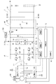
図1、図2には、実施例1に係る風車制御装置2を用いた風力発電システム1を示している。図1の風力発電システム1は、主として、風車100、発電機3、風車制御装置2、バッテリ(battery)60、回転速度センサ7、風速センサ9などを備えている。この風力発電システム1は、風車100の回転時に発電機3で電力を発生させ、所望の出力に変換した上でバッテリ60の充電や、外部出力端子62からの出力を行う装置として構成されている。
本発明を具体化した実施例1について、図面を参照しつつ説明する。
図1、図2には、実施例1に係る風車制御装置2を用いた風力発電システム1を示している。図1の風力発電システム1は、主として、風車100、発電機3、風車制御装置2、バッテリ(battery)60、回転速度センサ7、風速センサ9などを備えている。この風力発電システム1は、風車100の回転時に発電機3で電力を発生させ、所望の出力に変換した上でバッテリ60の充電や、外部出力端子62からの出力を行う装置として構成されている。
図1、図2で示す風車100は、例えば、垂直軸型風車として構成されており、鉛直方向に延びる回転軸の周囲に複数の直線翼を一体回転可能に連結させた直線翼垂直軸風車などによって構成されている。図3のように、風車100は、所定方向(回転軸部102の軸方向である上下方向)に延びる複数の翼部104と棒状に構成されるとともに所定方向に延びる回転軸部102とを備え、複数の翼部104が回転軸部102の上端部付近に連結された形で複数の翼部104と回転軸部102とが一体的に構成されている。回転軸部102は、例えば鉛直上下方向に延びるように図示しない軸受によって回転可能に保持されている。図3の例では、回転軸部102の下端部側の部分が発電機3における図示しない回転子と一体化され、回転軸部102と回転子とが一体的に回転する構成をなす。また、回転軸部102の下端寄りの所定位置には円板状の被作用部106が回転軸部102の周囲に張り出す形で回転軸部102と一体的に構成されている。被作用部106は、回転軸部102の軸方向を厚さ方向とし、外縁部が回転軸部102の回転軸線を中心とした円形形状をなしている。なお、ここで示す例はあくまで一例であり、公知の様々な風車を用いることができる。
図1、図2で示す発電機3は、風車100の回転力を変換して電力を生じさせる装置であり、例えば、三相交流発電機として構成され、風車100の回転と連動して回転する回転子と、固定子巻線3A,3B,3C(図4)が巻かれるとともに回転子に近接して配置される固定子とを備える。例えば、発電機3は、回転子が風車100の回転軸に連結されて回転軸部102(図3)と一体的に回転する構成をなし、回転子の回転時には各相の導電路74,75,76に三相交流が発生する構成をなす。
図1のように、風車制御装置2は、制御部10、整流・昇圧部50、回転抑制部20、第2電気ブレーキ部30、降圧部40、検出部91,92、回転速度センサ7、風速センサ9、各配線部などによって構成され、発電機3からの出力電力を制御するとともに風車100の回転を制御する装置として機能する。
整流・昇圧部50は、発電機3に発電動作を行わせる場合には昇圧チョッパ(chopper)回路として作動し、発電機3を電動機として動作させる場合にはインバータ(inverter)として作動する回路である。
図2のように、整流・昇圧部50は、発電機3の各相の導電路74,75,76にそれぞれ設けられたコイル(coil)L1,L2,L3、コイルL1に接続される一対のスイッチ(switch)素子Sa1,Sb1、コイルL2に接続される一対のスイッチ素子Sa2,Sb2、コイルL3に接続される一対の半導体スイッチ素子Sa3,Sb3をそれぞれ備える。スイッチ素子Sa1,Sb1,Sa2,Sb2,Sa3,Sb3は、例えばIGBTなどの半導体スイッチ素子によって構成され、それぞれのゲート(gate)には、駆動部14からの駆動信号が個別に入力される。
このように構成される整流・昇圧部50は、発電制御時には、発電機3で発生する交流電圧を直流電圧に変換し且つ入力電力を昇圧して出力するように機能する。また、整流・昇圧部50は、アシスト(assist)制御時には、供給される直流電力(例えば外部電源130から供給される直流電力)を三相交流に変換し、発電機3に三相交流電力を供給することで発電機3を電動機として回転駆動するように機能する。なお、アシスト制御時の供給電力は、バッテリ60からの電力であってもよい。
回転抑制部20は、風車100の回転を抑制する抑制動作(回転速度を減速する減速動作)と、抑制動作の解除とを行う部分である。回転抑制部20は、第1電気ブレーキ部21と機械ブレーキ部22とによって構成されている。
機械ブレーキ部22は、第2ブレーキ部の一例に相当し、風車100に対してブレーキ動作を行い得る装置である。図3にて概念的に示すように、機械ブレーキ部22は、ブレーキ動作部24と駆動回路26とを備える。ブレーキ動作部24は、例えば、逆作動型の空圧ブレーキとして構成され、風車100の一部として構成された被作用部106に作用する一対の接触部材24Bと、これら接触部材24Bを駆動するアクチュエータ(actuator)24Aとを備える。被作用部106は、例えば、風車100の回転軸部102に一体的に組み付けられた円板状のディスク(disk)として構成され、風車100に設けられた複数の翼部104と一体的に回転する構成をなしている。機械ブレーキ部22は、アクチュエータ24Aによって接触部材24Bを被作用部106に接近させて接触させることでブレーキ力を生じさせる第2ブレーキ動作と、アクチュエータ24Aによって接触部材24Bを被作用部106から離間させてブレーキ力を解除する動作(第2ブレーキ動作の解除)とを行う装置である。
駆動回路26は、制御部10から駆動指令が与えられた場合にアクチュエータ24Aを駆動し、一対の接触部材24Bを互いに接近させて被作用部106を挟み込ませるようにアクチュエータ24Aを動作させる。このように接触部材24Bが被作用部106に接触することで、これらの間で生じる摩擦力が風車100の回転を減速させる力(ブレーキ力)となる。また、駆動回路26は、制御部10から停止指令が与えられた場合、アクチュエータ24Aに対し、一対の接触部材24Bを退避位置(被作用部106に接触しない位置)で保持させる。上述した第2ブレーキ動作中に駆動回路26に停止指令が与えられた場合、駆動回路26は、被作用部106を挟み込んでいる一対の接触部材24Bを互いに離間させて被作用部106から離すようにアクチュエータ24Aを動作させる。このようにアクチュエータ24Aによって一対の接触部材24Bを被作用部106から離間させることで、接触部材24Bが被作用部106に接触して生じていた摩擦力が発生しなくなり、風車100に対するブレーキ力が解除される。
第1電気ブレーキ部21は、第1ブレーキ部の一例に相当し、発電機3に対する電気的な制御を行い得る回路として構成されている。第1電気ブレーキ部21は、発電機3において風車100の回転力に逆らう力を生じさせる第1ブレーキ動作と、この第1ブレーキ動作の解除とを行い得る回路であり、具体的には例えば図4のような回路として構成される。
図4の回路構成では、各巻線3A,3B,3Cにそれぞれ接続された各相の導電路74,75,76のそれぞれにおいて、整流・昇圧部50側に続く経路から分岐する形で分岐路21A,21B,21Cがそれぞれ設けられている。そして、各分岐路21A,21B,21Cには、抵抗部R1,R2,R3がそれぞれ介在している。また、各分岐路21A,21B,21Cは、接続路21Dによって互いに接続されている。分岐路21A,21B,21Cでは、いずれかの分岐路から他の分岐路へと電流が流れる場合に抵抗にて電流が流れ、抵抗で電圧降下が発生するようになっている。また、分岐路21B,21Cには、それぞれを通電可能状態と通電遮断状態に切替えるスイッチSW1,SW2が設けられ、このスイッチSW1,SW2のオンオフが制御部10によって制御されるようになっている。制御部10は、後述する第1ブレーキ動作を行う場合、スイッチSW1,SW2をオン状態にする制御を行い、第1ブレーキ動作を行わない場合、スイッチSW1,SW2をオフ状態にする制御を行う。スイッチSW1,SW2がオン状態である場合、分岐路21A,21B,21Cの相互で電流が流れ、スイッチSW1,SW2がオフ状態である場合、分岐路21A,21B,21Cにおいて分岐路間では電流が流れない。制御部10がスイッチSW1,SW2をオン状態にした場合、導電路74,75,76を流れる電流が上昇するため、発電機3の回転子が回転する際の回転負荷を増大させることができ、その結果、発電機3の回転子と連動する風車100の回転にブレーキをかけることができる。本構成では、完全に短絡するのではなく、抵抗部を介して導電路間を電気的に接続するため、短絡状態でブレーキを継続しすぎることに起因する過熱等を防ぐことができ、絶縁性能の維持等の面で有利である。また、回転速度によっては、短絡の場合よりも大きなトルクを発生させることができる。
第2電気ブレーキ部30は、整流・昇圧部50から出力される出力電力の一部を消費するための部分である。この第2電気ブレーキ部30は、抵抗34、ダイオード(diode)36、スイッチ素子32などを備える。スイッチ素子32は、例えばIGBTなどの半導体スイッチ素子によって構成され、駆動部15からの制御信号によってオンオフが制御される。
第2電気ブレーキ部30は、導電路71と導電路72の間に抵抗34及びスイッチ素子32が直列に接続され、スイッチ素子32のオン動作に応じて抵抗34に電流を流し、整流・昇圧部50から出力される電力の一部を消費させるように機能する。スイッチ素子32のゲートには駆動部15から出力されるPWM(Pulse Width Modulation)信号が入力され、第2電気ブレーキ部30での消費電力量はPWM信号のデューティ(duty)によって制御される。
コンデンサ(condenser)55は、導電路71と導電路72との間に接続されている。このコンデンサ55は、降圧部40に入力される入力電流を平滑化する機能を有する。
降圧部40は、公知の降圧コンバータ(converter)として構成され、導電路71の通電をオンオフするスイッチ素子42と、ダイオード44と、コイル48と、コンデンサ46とを備える。スイッチ素子42は、例えばMOSFETなどによって構成され、駆動部16からのPWM信号に応じてオンオフする構成をなす。
バッテリ60は、例えば、公知の二次電池として構成されており、風力発電システム1を構成する様々な負荷を駆動するための電源として機能する。図示はしていないが、風力発電システム1には、バッテリ60からの電力に基づいて複数の電源電圧を生成する電源回路が設けられており、例えば制御部10には、電源回路で生成された電源電圧が印加される。バッテリ60の正側の端子と出力側導電路81との間には、スイッチ61が設けられ、制御部10によってスイッチ61のオンオフが制御される。
回転速度センサ7は、風車100の回転速度を検出する検出部の一例に相当する。この回転速度センサ7は、風車100の回転軸部102の回転速度を検出し得るセンサであればよく、公知の様々な回転速度センサを用いることができる。制御部10は、回転速度センサ7からの出力値を取得して風車100の回転速度を把握する。
風速センサ9は、公知の風速センサによって構成され、風車100の近傍の風速を計測するように機能する。この風速センサ9は、風車100の所定位置(例えば回転翼以外の部位)に取り付けられ、風速センサ9が取り付けられた位置の風速を示す値を出力する。制御部10は、風速センサ9からの出力値(検出値)を取得して、風車付近の風速を把握する。
制御部10は、例えば、マイクロコンピュータ(microcomputer)などからなる制御回路12と、ROM、RAMなどからなる記憶部18と、制御信号を出力する複数の駆動部14,15,16などを備えている。制御部10には、回転速度センサ7や風速センサ9からの出力値以外にも、様々な検出値が入力される。例えば、図1で示す検出部91は、電流センサ及び電圧センサを備え、整流・昇圧部50から出力される出力電流及び出力電圧が検出部91によって検出され、制御部10に入力される。検出部92は、電流センサ及び電圧センサを備え、降圧部40から出力される出力電流及び出力電圧が検出部92によって検出され、制御部10に入力される。
風力発電システム1の出力端子62は、例えば、蓄電池システム120の入力端子122に接続可能とされている。即ち、風力発電システム1で発生した電力が、出力端子62を介して外部の蓄電池システム120に供給し得るように構成されている。なお、図1、図2の例では、風力発電システム1で生じた電力を蓄電池システム120に供給する例を示したが、系統連系のための構成を付加し、商用電源系統に接続してもよい。
このように構成される風力発電システム1は、風車100が風力を受けて回転し且つ制御部10が発電制御を実行しているときには、発電機3の発電によって得られた電力を変換して出力する。但し、風速センサ9によって検出される風速が所定閾値を超える場合には、後述する回転抑制モードの制御又は回転停止制御を行い、風車100の回転を減速又は停止させる。
ここで、風車制御装置2の動作について説明する。
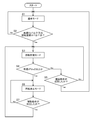
風車制御装置2では、制御部10が、図5のような流れで回転抑制部20を所定の動作解除状態とする通常モードの制御と、回転抑制部20を動作させつつ風車100を回転させる回転抑制モードの制御と、風車100を停止させる停止モードの制御とを行う。そして、制御部10は、通常モードの制御を行っているときに風速センサ9で計測される風速が所定値(第1風速閾値Vw1)以上になった場合、風速センサ9で計測される風速が上昇する風速上昇時に風速が大きいほど風車100の回転速度を小さくする上昇対応制御を実行するように回転抑制モードの制御を行うようになっている。
風車制御装置2では、制御部10が、図5のような流れで回転抑制部20を所定の動作解除状態とする通常モードの制御と、回転抑制部20を動作させつつ風車100を回転させる回転抑制モードの制御と、風車100を停止させる停止モードの制御とを行う。そして、制御部10は、通常モードの制御を行っているときに風速センサ9で計測される風速が所定値(第1風速閾値Vw1)以上になった場合、風速センサ9で計測される風速が上昇する風速上昇時に風速が大きいほど風車100の回転速度を小さくする上昇対応制御を実行するように回転抑制モードの制御を行うようになっている。
制御部10は、例えば、所定の運転開始条件を満たす場合(例えば、回転速度センサ7によって検出される風車100の回転速度が所定の発電開始回転速度以上であり、後述する回転抑制モード及び回転停止モードでない場合)に図5で示す風車制御を開始する。制御部10は、図5の制御を開始した場合、まず、ステップ(step)S1にて通常モードの制御を開始する。制御部10は、通常モードの制御を開始した後、ステップS2において、風速センサ9で計測される風速が第1風速閾値(所定値)Vw1以上である条件、又は回転速度センサ7で検出される回転速度が第1回転速度閾値Vr1以上である条件を満たすか否かを判断する。制御部10は、風速センサ9で計測される風速が第1風速閾値(所定値)Vw1未満となっており且つ回転速度センサ7で検出される回転速度が第1回転速度閾値Vr1未満となっている間は、ステップS2でNoとする判断を繰り返し、この期間は、通常モードでの発電制御を継続する。
制御部10は、通常モードの発電制御を行う場合、各スイッチ素子Sa1,Sb1,Sa2,Sb2,Sa3,Sb3に対し制御信号を出力し、整流・昇圧部50を三相昇圧チョッパ回路として動作させる。
本構成では、例えば回転速度(回転数)と出力目標値(発電機回生出力)とが予め対応付けられており、このように回転速度と出力目標値とを対応付けた対応データが記憶部18に記憶されている。このような対応データが存在するため、回転速度センサ7によって回転速度が定まれば対応データを参照してその回転速度(回転数)に対応付けられた出力目標値(発電機回生出力)を決めることができる。また、各回転速度に対応する各出力目標値は、各回転速度のときの最大電力値であり、回転速度(回転数)の三乗に比例するように設定されている。
制御部10は、整流・昇圧部50を三相昇圧チョッパ回路として動作させる場合、回転速度センサ7で検出された風車100の回転速度(回転数)と、記憶部18に記憶された回転速度毎の出力目標値(各回転速度に対応する最大電力値)とに基づき、整流・昇圧部50からの出力電力が、風車100の回転速度(回転数)に対応する出力目標値(最大電力値)となるようにMPPT(Maximum Power Point Tracking)制御を行う。具体的には、制御部10は、検出部91で検出される出力電流及び出力電圧によって決定する出力電力が目標値(最大電力値)となるように整流・昇圧部50に与えるPWM信号のデューティを調整しながらフィードバック(feedback)制御を繰り返す。
なお、このように通常モードの制御を実行しているときに所定の運転終了条件が成立した場合(例えば、風車の回転速度が所定の運転停止閾値未満となった場合)図5の制御を一旦終了し、その後に運転開始条件が成立するまで動作を停止してもよい。この場合、運転開始条件が成立した時に、再び図5の制御を実行すればよい。
制御部10は、通常モードの実行中にステップS2の判断を繰り返し、風速センサ9で計測される風速が第1風速閾値(所定値)Vw1以上となった場合、又は、回転速度センサ7で検出される回転速度が第1回転速度閾値Vr1以上となった場合(図5のステップS2でYesの場合)、ステップS3において回転抑制モードの制御に切り替える。
制御部10は、ステップS2からステップS3への以降によって回転抑制モードの制御に切り替えた場合、図6のようなテーブルデータ(table data)に従って制御を行う。図6のテーブルデータは、第1風速閾値Vw1(所定値)以上且つ第2風速閾値Vw2未満の風速範囲における複数段階の風速レベルと複数段階の回転速度レベルとを定めるとともに風速レベルが大きいほど回転速度レベルが小さくなるように風速レベルと回転速度レベルとを対応付けた対応データである。このテーブルデータ(対応データ)は、記憶部18に記憶されている。なお、図6のテーブルデータは、大きいテーブル番号ほど、対応付けられた風速レベル(風速範囲)が小さく且つ対応付けられた回転速度レベルが大きくなっている。
なお、図6の例では、第1風速閾値Vw1が11(m/s)であり、第2風速閾値Vw2が22(m/s)である。例えば、テーブル番号6には、11(m/s)以上12(m/s)未満の風速レベル及び180(min-1)の回転速度レベルが対応付けられ、テーブル番号5には、12(m/s)以上13(m/s)未満の風速レベル及び170(min-1)の回転速度レベルが対応付けられ、テーブル番号4には、13(m/s)以上14(m/s)未満の風速レベル及び160(min-1)の回転速度レベルが対応付けられ、テーブル番号3には、14(m/s)以上16(m/s)未満の風速レベル及び150(min-1)の回転速度レベルが対応付けられ、テーブル番号2には、16(m/s)以上18(m/s)未満の風速レベル及び140(min-1)の回転速度レベルが対応付けられ、テーブル番号1には、18(m/s)以上20(m/s)未満の風速レベル及び120(min-1)の回転速度レベルが対応付けられ、テーブル番号0には、20(m/s)以上22(m/s)未満の風速レベル及び100(min-1)の回転速度レベルが対応付けられている。
図5のように、制御部10は、回転抑制モードの制御を開始した後、風速が第2風速閾値Vw2以上となるか又は所定の復帰条件が成立するまで回転抑制モードの制御を継続する。一方、回転抑制モードの制御を行っているときに風速が第2風速閾値Vw2以上となった場合(ステップS4でYesの場合)にはステップS6に移行して停止モードの制御に切り替える。また、回転抑制モードの制御を行っているときに所定の復帰条件が成立した場合(ステップS5でYesの場合)にはステップS1に移行して通常モードの制御に切り替える。
制御部10は、回転抑制モードの制御を行う場合、図6で示すテーブルデータに基づき、風速センサ9で計測される風速が上昇する風速上昇時には対応データにおいて風速センサ9で計測される風速レベルに対応付けられた回転速度レベル又は対応付けられた回転速度レベルから所定段階シフトしたレベルを目標とするように風車100の回転速度を制御する上昇対応制御を実行し、風速センサ9で計測される風速が下降する風速下降時には対応データにおける複数段階の回転速度レベルに基づいて風車100の回転速度を所定制限数以内の段階数ずつ大きくするように下降対応制御を実行する。なお、以下では、所定制限数が「2」である例について説明する。
具体的には、ステップS2からステップS3に移行した直後(即ち、風速が第1風速閾値(所定値)Vw1以上又は風車100の回転速度が第1回転速度閾値Vr1以上となった直後)には、番号が最も大きい最上位のテーブル番号が選択される。その後、制御部10は、風速センサ9で計測される風速及び回転速度センサ7で検出される回転速度を監視し、風速センサ9で計測される風速が変化前の現在レベルよりも大きい新たな風速レベルに変化した場合、当該新たな風速レベルに対して対応データで対応付けられた回転速度レベルから所定段階シフトしたレベルを目標とするように風車の回転速度を制御する。
例えば、ステップS2からステップS3に移行した直後の風速が、11(m/s)である場合、即ち、変化前の現在レベルがテーブル番号6(現テーブル番号)に対応する風速レベル(11(m/s)~12(m/s))である場合において、その後に、風速が14(m/s)となることで、変化前の現在レベルよりも大きい新たな風速レベル(テーブル番号3に対応する風速レベル(14(m/s)~16(m/s))に変化した場合、この新たな風速レベル(14(m/s)~16(m/s))に対応するテーブル番号3(新テーブル番号)に対して図6で示す対応データで対応付けられた回転速度レベル(150min-1)から1段階低くシフトした回転速度レベル(140min-1)を目標とするように風車の回転速度を制御する。
なお、ここで示す例はあくまで一例であり、回転抑制モードの実行中に、計測される風速のレベルが1段階以上大きくなるように切り替わった場合には、切り替わり後の風速レベルに対応付けられた回転速度よりも1段階低い回転速度に制御することになる。
一方で、制御部10は、回転抑制モードの制御の実行中に風速センサ9で計測される風速が変化前の現在レベルよりも小さい風速レベル以下で一定時間(例えば、5秒)以上維持された場合、制御中の回転速度レベルよりも所定の制限段階数以内で大きい回転速度レベルを目標とするように風車の回転速度を制御する下降対応制御を実行する。本構成では、所定の制限段階数が「2」であり、風速が大きく低下した状態が維持されても、回転速度のレベルが一度に2段階以上切り替わらないようになっている。
例えば、ある時期の風速が16m/sであり、変化前の現在レベルがテーブル番号2(現テーブル番号)に対応する風速レベル(16(m/s)~18(m/s))であり、対応データにおいてこの風速レベルに対応する回転速度レベル(140min-1)から1段階シフトさせた回転速度レベル(120min-1)で制御されている場合において、その後に、風速が12(m/s)となることで、変化前の現在レベルよりも小さい新たな風速レベル(テーブル番号5に対応する風速レベル(12(m/s)~13(m/s))に変化し、このような1段階以上のレベル低下が一定時間(例えば、5秒)以上維持された場合、この新たな風速レベル(12(m/s)~13(m/s))に対応するテーブル番号5に応じた回転速度に切り替えるのではなく、変化前の現在レベルのテーブル番号2(現テーブル番号)に対して1加算したテーブル番号3(新テーブル番号)に対して図6で示す対応データで対応付けられた回転速度レベル(150min-1)を目標とするように風車の回転速度を制御する。つまり、目標回転速度を、変化前の回転速度レベルである(120min-1)から制限段階数である「2段階」だけ増加させた(150min-1)に切り替え、この新たな回転速度で風車100を制御する。
また、制御部10は、回転抑制モードの制御の実行中に、所定値(第1風速閾値Vw1である11(m/s))以上の風速範囲における複数段階の風速レベル(図6)において最も小さい風速レベル(即ち、最上位のテーブル番号6に対応する風速レベルである11~12(m/s))に対して対応データ(図6)で対応付けられた最高回転速度レベル(即ち、図6で示す180min-1)を目標とするように風車100の回転速度を制御していた場合、風速センサ9で計測される風速が上記所定値(第1風速閾値Vw1である11(m/s))未満で所定時間(例えば、5秒)以上維持されたことを条件として通常モードの制御に切り替える。つまり、「回転抑制モードの制御の実行中に、最上位のテーブル番号6に対応する風速レベル(11~12(m/s))に対応する回転速度レベル(180min-1)を目標とするように風車100の回転速度を制御していた場合に、風速センサ9で計測される風速が上記所定値(第1風速閾値Vw1である11(m/s))未満で所定時間(例えば、5秒)以上維持されたこと」が復帰条件であり、このような復帰条件が成立した場合、図5のステップS5においてYesとなり、ステップS1にて通常モードの制御を実行することになる。
また、制御部10は、回転抑制モードの制御の実行中に、風速センサ9で計測される風速が第2風速閾値Vw2以上となった場合(即ち、図5のステップS4でYesの場合)、ステップS6において停止モードの制御を実行する。停止モードの制御中は、例えば、風車100の回転速度が0となるまで上述した第1電気ブレーキ部21及び機械ブレーキ部22を動作させて風車100の回転を停止させる。そして、所定の解除条件が成立するまで風車100を回転停止状態で維持する。解除条件は様々に設定することができ、例えば、「風速センサ9で計測される風速が、所定の解除判定閾値未満で一定時間以上維持されること」とすることができる。所定の解除判定閾値は、第2風速閾値Vw2であってもよく、第2風速閾値Vw2よりも小さい値であってもよい。図5の例では、停止モードを解除する場合、ステップS3以降の処理を実行することになる。
次に、風車制御装置2の効果を例示する。
風車制御装置2において、制御部10は、通常モードの制御を行っているときに風速センサ9で計測される風速が所定値Vw1以上になった場合、少なくとも風速センサ9で計測される風速が上昇する風速上昇時に風速が大きいほど風車100の回転速度を小さくする上昇対応制御を実行するように回転抑制モードの制御を行う。このように風速センサ9で計測される風速が所定値Vw1以上になった場合に回転抑制モードの制御を行うため、風速が急上昇して所定値Vw1以上となった場合、回転速度が大きく上昇する前に迅速に回転抑制動作が行われやすくなる。更に、回転抑制モードでは、風速上昇時に風速が大きいほど風車100の回転速度を小さくするように上昇対応制御を実行するため、過回転が生じる可能性が大きくなる風速状況であるほどその状況を反映して回転抑制度合いを強めることができる。
風車制御装置2において、制御部10は、通常モードの制御を行っているときに風速センサ9で計測される風速が所定値Vw1以上になった場合、少なくとも風速センサ9で計測される風速が上昇する風速上昇時に風速が大きいほど風車100の回転速度を小さくする上昇対応制御を実行するように回転抑制モードの制御を行う。このように風速センサ9で計測される風速が所定値Vw1以上になった場合に回転抑制モードの制御を行うため、風速が急上昇して所定値Vw1以上となった場合、回転速度が大きく上昇する前に迅速に回転抑制動作が行われやすくなる。更に、回転抑制モードでは、風速上昇時に風速が大きいほど風車100の回転速度を小さくするように上昇対応制御を実行するため、過回転が生じる可能性が大きくなる風速状況であるほどその状況を反映して回転抑制度合いを強めることができる。
風車制御装置2は、少なくとも所定値Vw1以上の風速範囲における複数段階の風速レベルと複数段階の回転速度レベルとを定めるとともに風速レベルが大きいほど回転速度レベルが小さくなるように風速レベルと回転速度レベルとを対応付けた対応データを記憶する記憶部18を有する。制御部10は、回転抑制モードの制御を行う場合、風速センサ9で計測される風速が上昇する風速上昇時には対応データにおいて風速センサ9で計測される風速レベルに対応付けられた回転速度レベルから所定段階(例えば、1段階)シフトしたレベルを目標とするように風車100の回転速度を制御する上昇対応制御を実行し、風速センサ9で計測される風速が下降する風速下降時には対応データにおける複数段階の回転速度レベルに基づいて風車100の回転速度を所定制限数以内の段階数ずつ大きくするように下降対応制御を実行する。
この風車制御装置2は、制御部10が回転抑制モードの制御を行う場合、風速上昇時には対応データにおいて風速センサ9で計測される風速レベルに対応付けられた回転速度レベルから所定段階シフトしたレベルを目標とするように風車100の回転速度を制御する上昇対応制御を実行するため、風速上昇時には風速に応じた回転速度に即座に切り替えることができる。よって、風速の急上昇に起因する過回転の発生を防ぎやすくなる。一方、風速下降時には、対応データにおける複数段階の回転速度レベルに基づいて風車100の回転速度を所定制限数以内の段階数ずつ大きくするように下降対応制御を実行するため、風速が低く安定している状況下で少しずつ回転速度を戻すことができる。例えば風速が一時的に急低下した後に急上昇するような事態が生じたとしても、風速の急低下時に回転数がそれほど増大しないため、その後に風速が急上昇しても風車100の過回転は生じにくくなる。
制御部10は、回転抑制モードの制御の実行中に風速センサ9で計測される風速が変化前の現在レベルよりも新たな風速レベルに変化した場合、当該新たな風速レベルに対して対応データで対応付けられた回転速度レベルから所定段階シフトしたレベルを目標とするように風車の回転速度を制御する。
この風車制御装置2は、回転抑制モードの制御の実行中に風速センサ9で計測される風速のレベルが1段階以上上昇した場合、風車100の回転速度を、その上昇した風速レベルに応じて低い回転速度レベルに迅速に切り替えることができる。
制御部10は、回転抑制モードの制御の実行中に風速センサ9で計測される風速が変化前の現在レベルよりも小さい風速レベル以下で一定時間以上維持された場合、制御中の回転速度レベルよりも所定の制限段階数以内で大きい回転速度レベルを目標とするように風車の回転速度を制御する下降対応制御を実行する。
この風車制御装置2は、風速が1段階以上下降した状態が一定時間以上安定的に維持されていることを条件として回転速度のレベルを所定の制限段階数以内で上げるため、風速が急上昇する可能性が低い状態を確実に確認しながら慎重性を重視して回転レベルを段階的に上げることができる。
制御部10は、回転抑制モードの制御の実行中に、所定値以上の風速範囲における複数段階の風速レベルにおいて最も小さい風速レベルに対して対応データで対応付けられた最高回転速度レベルを目標とするように風車100の回転速度を制御していた場合、風速センサ9で計測される風速が所定値未満で所定時間以上維持されたことを条件として通常モードの制御に切り替えるように機能する。
この風車制御装置2は、回転抑制モードの制御が実行された場合、最高回転速度レベルまで回転速度が下げられた上で風速が所定値未満で所定時間以上維持されないと通常モードの制御に切り替わらないため、風速が安定的に低い状況に限定して通常モードに切り替えることができる。
<他の実施例>
本発明は上記記述及び図面によって説明した実施例に限定されるものではなく、例えば次のような実施例も本発明の技術的範囲に含まれる。
(1)実施例1は、風車100として垂直軸型風車を例示したが、水平軸型風車であってもよい。発電機3の回転子に対して直接又は間接的に駆動力を与え得る風車であれば、公知のあらゆる種類の風車に適用することができる。
(2)実施例1では、図3において機械ブレーキ部22(第2ブレーキ部)の一例を示したが、第2ブレーキ部は、風車100に対して機械的な接触によってブレーキ力を与え得る構成であればよく、回転体に対してブレーキ力を与える機能を備えた公知の様々な機械ブレーキを用いることができる。例えば、特開2011-256723号公報で開示されるような機械式ブレーキを用いてもよい。また、風車100及びこれに連動する部材に対する機械ブレーキ部22の接触部位は、実施例1の被作用部106の位置に限定されない。例えば、機械ブレーキ部22の接触部材(アクチュエータによって駆動される部材)は、風車100と連動する連動部材(例えば、歯車伝動などによって風車100と連動する部材)を被作用部とし、この連動部材(被作用部)に接触部材を接触させつつブレーキ力を生じさせるように第2ブレーキ動作を行う構成であってもよい。
(3)実施例1では、図4において第1電気ブレーキ部21(第1ブレーキ部)の一例を示したが、第1ブレーキ部は、電気的な制御によって発電機の回転にブレーキ力を生じさせ得る構成であれば、公知の様々な電気ブレーキを用いることができる。また、図4の例では、抵抗部R1,R2,R3を用いたが、これらを省略して短絡させるようにしてもよい。
(4)実施例1では、回転抑制モード時において風速が1段階以上上昇した時に、上昇した風速に対応付けられた回転速度よりも1段階シフトした低いレベル(回転速度)を目標とするように目標回転速度を切り替えたが、この例に限定されず、回転抑制モード時において風速が1段階以上上昇した時に、上昇した風速に対応付けられた回転速度よりも2段階シフトした低いレベル(回転速度)を目標とするように目標回転速度を切り替えてもよく、上昇した風速に対応付けられた回転速度を目標とするように目標回転速度を切り替えてもよい。
(5)実施例1では、「所定制限数」「制限段階数」を2とし、風速が下降して安定しているときに回転速度レベルを2段階以内で段階的に下げる例を示した。必ず1段階ずつ下げるようにしてもよい。
(6)実施例1では、対応データの一例として、図6で概念的に示すようなテーブルデータを例示したが、図6は、対応データのあくまで一例である。テーブルデータを対応データとして採用する場合、図6のようなテーブル構成に限定されず、風速範囲をより細かく区分けして各風速範囲に回転速度を対応付けたテーブル構成であってもよく、風速範囲をより大まかに区分けしてもよい。或いは、図6のような対応データを用いず、風速レベルが大きいほど回転速度レベルが小さくなるように風速レベルと回転速度レベルとを対応付けた演算式などによって風速レベルに応じた回転速度を決定するようにしてもよい。
本発明は上記記述及び図面によって説明した実施例に限定されるものではなく、例えば次のような実施例も本発明の技術的範囲に含まれる。
(1)実施例1は、風車100として垂直軸型風車を例示したが、水平軸型風車であってもよい。発電機3の回転子に対して直接又は間接的に駆動力を与え得る風車であれば、公知のあらゆる種類の風車に適用することができる。
(2)実施例1では、図3において機械ブレーキ部22(第2ブレーキ部)の一例を示したが、第2ブレーキ部は、風車100に対して機械的な接触によってブレーキ力を与え得る構成であればよく、回転体に対してブレーキ力を与える機能を備えた公知の様々な機械ブレーキを用いることができる。例えば、特開2011-256723号公報で開示されるような機械式ブレーキを用いてもよい。また、風車100及びこれに連動する部材に対する機械ブレーキ部22の接触部位は、実施例1の被作用部106の位置に限定されない。例えば、機械ブレーキ部22の接触部材(アクチュエータによって駆動される部材)は、風車100と連動する連動部材(例えば、歯車伝動などによって風車100と連動する部材)を被作用部とし、この連動部材(被作用部)に接触部材を接触させつつブレーキ力を生じさせるように第2ブレーキ動作を行う構成であってもよい。
(3)実施例1では、図4において第1電気ブレーキ部21(第1ブレーキ部)の一例を示したが、第1ブレーキ部は、電気的な制御によって発電機の回転にブレーキ力を生じさせ得る構成であれば、公知の様々な電気ブレーキを用いることができる。また、図4の例では、抵抗部R1,R2,R3を用いたが、これらを省略して短絡させるようにしてもよい。
(4)実施例1では、回転抑制モード時において風速が1段階以上上昇した時に、上昇した風速に対応付けられた回転速度よりも1段階シフトした低いレベル(回転速度)を目標とするように目標回転速度を切り替えたが、この例に限定されず、回転抑制モード時において風速が1段階以上上昇した時に、上昇した風速に対応付けられた回転速度よりも2段階シフトした低いレベル(回転速度)を目標とするように目標回転速度を切り替えてもよく、上昇した風速に対応付けられた回転速度を目標とするように目標回転速度を切り替えてもよい。
(5)実施例1では、「所定制限数」「制限段階数」を2とし、風速が下降して安定しているときに回転速度レベルを2段階以内で段階的に下げる例を示した。必ず1段階ずつ下げるようにしてもよい。
(6)実施例1では、対応データの一例として、図6で概念的に示すようなテーブルデータを例示したが、図6は、対応データのあくまで一例である。テーブルデータを対応データとして採用する場合、図6のようなテーブル構成に限定されず、風速範囲をより細かく区分けして各風速範囲に回転速度を対応付けたテーブル構成であってもよく、風速範囲をより大まかに区分けしてもよい。或いは、図6のような対応データを用いず、風速レベルが大きいほど回転速度レベルが小さくなるように風速レベルと回転速度レベルとを対応付けた演算式などによって風速レベルに応じた回転速度を決定するようにしてもよい。
1…風力発電システム
2…風車制御装置
3…発電機
7…回転速度センサ(検出部)
9…風速センサ
10…制御部
18…記憶部
20…回転抑制部
100…風車
2…風車制御装置
3…発電機
7…回転速度センサ(検出部)
9…風速センサ
10…制御部
18…記憶部
20…回転抑制部
100…風車
Claims (5)
- 風車の回転力を変換して電力を生じさせる発電機と、風速を計測する風速センサと、を備えた風力発電システムにおいて前記風車を制御する風車制御装置であって、
前記風車の回転を抑制する回転抑制部と、
前記風車の回転速度を検出する検出部と、
前記回転抑制部を所定の動作解除状態とする通常モードの制御と、前記回転抑制部を動作させつつ前記風車を回転させる回転抑制モードの制御とを少なくとも行う制御部と、
を有し、
前記制御部は、前記通常モードの制御を行っているときに前記風速センサで計測される風速が所定値以上になった場合、少なくとも前記風速センサで計測される風速が上昇する風速上昇時に風速が大きいほど前記風車の回転速度を小さくする上昇対応制御を実行するように前記回転抑制モードの制御を行う風車制御装置。 - 少なくとも前記所定値以上の風速範囲における複数段階の風速レベルと複数段階の回転速度レベルとを定めるとともに風速レベルが大きいほど回転速度レベルが小さくなるように風速レベルと回転速度レベルとを対応付けた対応データを記憶する記憶部を有し、
前記制御部は、前記回転抑制モードの制御を行う場合、前記風速センサで計測される風速が上昇する風速上昇時には前記対応データにおいて前記風速センサで計測される風速レベルに対応付けられた回転速度レベル又は対応付けられた回転速度レベルから所定段階シフトしたレベルを目標とするように前記風車の回転速度を制御する前記上昇対応制御を実行し、前記風速センサで計測される風速が下降する風速下降時には前記対応データにおける複数段階の回転速度レベルに基づいて前記風車の回転速度を所定制限数以内の段階数ずつ大きくするように下降対応制御を実行する請求項1に記載の風車制御装置。 - 前記制御部は、前記回転抑制モードの制御の実行中に前記風速センサで計測される風速が変化前の現在レベルよりも大きい新たな風速レベルに変化した場合、当該新たな風速レベルに対して前記対応データで対応付けられた回転速度レベル又は前記対応データで対応付けられた回転速度レベルから所定段階シフトしたレベルを目標とするように前記風車の回転速度を制御する前記上昇対応制御を実行する請求項2に記載の風車制御装置。
- 前記制御部は、前記回転抑制モードの制御の実行中に前記風速センサで計測される風速が変化前の現在レベルよりも小さい風速レベル以下で一定時間以上維持された場合、制御中の回転速度レベルよりも所定の制限段階数以内で大きい回転速度レベルを目標とするように前記風車の回転速度を制御する前記下降対応制御を実行する請求項2又は請求項3に記載の風車制御装置。
- 前記制御部は、前記回転抑制モードの制御の実行中に、前記所定値以上の風速範囲における前記複数段階の風速レベルにおいて最も小さい風速レベルに対して前記対応データで対応付けられた最高回転速度レベルを目標とするように前記風車の回転速度を制御していた場合、前記風速センサで計測される風速が前記所定値未満で所定時間以上維持されたことを条件として前記通常モードの制御に切り替える請求項4に記載の風車制御装置。
Applications Claiming Priority (2)
| Application Number | Priority Date | Filing Date | Title |
|---|---|---|---|
| JP2016-239581 | 2016-12-09 | ||
| JP2016239581A JP6990022B2 (ja) | 2016-12-09 | 2016-12-09 | 風車制御装置 |
Publications (1)
| Publication Number | Publication Date |
|---|---|
| WO2018105232A1 true WO2018105232A1 (ja) | 2018-06-14 |
Family
ID=62490856
Family Applications (1)
| Application Number | Title | Priority Date | Filing Date |
|---|---|---|---|
| PCT/JP2017/036957 Ceased WO2018105232A1 (ja) | 2016-12-09 | 2017-10-12 | 風車制御装置 |
Country Status (2)
| Country | Link |
|---|---|
| JP (1) | JP6990022B2 (ja) |
| WO (1) | WO2018105232A1 (ja) |
Cited By (2)
| Publication number | Priority date | Publication date | Assignee | Title |
|---|---|---|---|---|
| CN114382644A (zh) * | 2021-12-01 | 2022-04-22 | 重庆海装风电工程技术有限公司 | 一种风力发电机组刹车自检方法、系统和存储介质 |
| CN116517789A (zh) * | 2023-05-26 | 2023-08-01 | 中国华能集团清洁能源技术研究院有限公司 | 一种识别风力发电机组变桨控制需求失效的方法及系统 |
Citations (2)
| Publication number | Priority date | Publication date | Assignee | Title |
|---|---|---|---|---|
| JP2004301116A (ja) * | 2003-03-19 | 2004-10-28 | Mitsubishi Electric Corp | 風力発電システム |
| JP2014202190A (ja) * | 2013-04-09 | 2014-10-27 | 株式会社リアムコンパクト | 制御装置、制御方法及びプログラム |
Family Cites Families (1)
| Publication number | Priority date | Publication date | Assignee | Title |
|---|---|---|---|---|
| JP5079092B2 (ja) | 2010-01-15 | 2012-11-21 | 三菱重工業株式会社 | 風力発電装置及びその起動方法 |
-
2016
- 2016-12-09 JP JP2016239581A patent/JP6990022B2/ja active Active
-
2017
- 2017-10-12 WO PCT/JP2017/036957 patent/WO2018105232A1/ja not_active Ceased
Patent Citations (2)
| Publication number | Priority date | Publication date | Assignee | Title |
|---|---|---|---|---|
| JP2004301116A (ja) * | 2003-03-19 | 2004-10-28 | Mitsubishi Electric Corp | 風力発電システム |
| JP2014202190A (ja) * | 2013-04-09 | 2014-10-27 | 株式会社リアムコンパクト | 制御装置、制御方法及びプログラム |
Cited By (2)
| Publication number | Priority date | Publication date | Assignee | Title |
|---|---|---|---|---|
| CN114382644A (zh) * | 2021-12-01 | 2022-04-22 | 重庆海装风电工程技术有限公司 | 一种风力发电机组刹车自检方法、系统和存储介质 |
| CN116517789A (zh) * | 2023-05-26 | 2023-08-01 | 中国华能集团清洁能源技术研究院有限公司 | 一种识别风力发电机组变桨控制需求失效的方法及系统 |
Also Published As
| Publication number | Publication date |
|---|---|
| JP2018096237A (ja) | 2018-06-21 |
| JP6990022B2 (ja) | 2022-01-12 |
Similar Documents
| Publication | Publication Date | Title |
|---|---|---|
| EP2884097B1 (en) | System and method for controlling a wind turbine system | |
| CN104718102B (zh) | 降额车辆电气驱动马达和发电机部件 | |
| KR101445023B1 (ko) | 전력 변환 장치 | |
| US8981584B2 (en) | Generator torque control methods | |
| JP2015533999A (ja) | 風力タービンヨー制御システム | |
| US9359996B2 (en) | Variable wind turbine having a power dissipating unit; a method of operating a power dissipating unit in a wind turbine | |
| JP6226566B2 (ja) | モータ制御装置及びそれを備えた建設機械 | |
| JP5483901B2 (ja) | 風力発電システム、及び風力発電システムの失速制御方法 | |
| JP6765760B2 (ja) | 風力発電用の風車制御装置 | |
| JP6990021B2 (ja) | 風力発電用の風車制御装置 | |
| US20130271093A1 (en) | Control apparatus of an ac generator for a vehicle | |
| JP2017204934A (ja) | 発電装置 | |
| WO2018105232A1 (ja) | 風車制御装置 | |
| JP2009225500A (ja) | モータ駆動装置およびその制御方法 | |
| JP6854662B2 (ja) | 風車発電装置 | |
| US20120181993A1 (en) | Wind turbine | |
| EP2706229A1 (en) | Turbine and control system of the over-power of said turbine | |
| JP6559563B2 (ja) | 風力発電用の出力制御装置 | |
| JP6578746B2 (ja) | 水力発電システム | |
| JP4774843B2 (ja) | 風力発電設備 | |
| JP6628595B2 (ja) | 風力発電用のアシスト制御装置 | |
| JP4398440B2 (ja) | 風力発電装置 | |
| JP2018135800A (ja) | 風力発電機の電気式ブレーキ装置 | |
| JP5272333B2 (ja) | モータ駆動装置およびモータ装置 | |
| WO2020009065A1 (ja) | 風力発電装置の出力制御装置 |
Legal Events
| Date | Code | Title | Description |
|---|---|---|---|
| 121 | Ep: the epo has been informed by wipo that ep was designated in this application |
Ref document number: 17879220 Country of ref document: EP Kind code of ref document: A1 |
|
| NENP | Non-entry into the national phase |
Ref country code: DE |
|
| 122 | Ep: pct application non-entry in european phase |
Ref document number: 17879220 Country of ref document: EP Kind code of ref document: A1 |