WO2018105196A1 - 気体濃縮装置 - Google Patents
気体濃縮装置 Download PDFInfo
- Publication number
- WO2018105196A1 WO2018105196A1 PCT/JP2017/033484 JP2017033484W WO2018105196A1 WO 2018105196 A1 WO2018105196 A1 WO 2018105196A1 JP 2017033484 W JP2017033484 W JP 2017033484W WO 2018105196 A1 WO2018105196 A1 WO 2018105196A1
- Authority
- WO
- WIPO (PCT)
- Prior art keywords
- adsorption
- adsorbent
- gas
- adsorption tank
- partition plate
- Prior art date
- Legal status (The legal status is an assumption and is not a legal conclusion. Google has not performed a legal analysis and makes no representation as to the accuracy of the status listed.)
- Ceased
Links
Images


Classifications
-
- B—PERFORMING OPERATIONS; TRANSPORTING
- B01—PHYSICAL OR CHEMICAL PROCESSES OR APPARATUS IN GENERAL
- B01D—SEPARATION
- B01D53/00—Separation of gases or vapours; Recovering vapours of volatile solvents from gases; Chemical or biological purification of waste gases, e.g. engine exhaust gases, smoke, fumes, flue gases, aerosols
- B01D53/02—Separation of gases or vapours; Recovering vapours of volatile solvents from gases; Chemical or biological purification of waste gases, e.g. engine exhaust gases, smoke, fumes, flue gases, aerosols by adsorption, e.g. preparative gas chromatography
- B01D53/04—Separation of gases or vapours; Recovering vapours of volatile solvents from gases; Chemical or biological purification of waste gases, e.g. engine exhaust gases, smoke, fumes, flue gases, aerosols by adsorption, e.g. preparative gas chromatography with stationary adsorbents
- B01D53/047—Pressure swing adsorption
-
- B—PERFORMING OPERATIONS; TRANSPORTING
- B01—PHYSICAL OR CHEMICAL PROCESSES OR APPARATUS IN GENERAL
- B01D—SEPARATION
- B01D53/00—Separation of gases or vapours; Recovering vapours of volatile solvents from gases; Chemical or biological purification of waste gases, e.g. engine exhaust gases, smoke, fumes, flue gases, aerosols
- B01D53/02—Separation of gases or vapours; Recovering vapours of volatile solvents from gases; Chemical or biological purification of waste gases, e.g. engine exhaust gases, smoke, fumes, flue gases, aerosols by adsorption, e.g. preparative gas chromatography
- B01D53/04—Separation of gases or vapours; Recovering vapours of volatile solvents from gases; Chemical or biological purification of waste gases, e.g. engine exhaust gases, smoke, fumes, flue gases, aerosols by adsorption, e.g. preparative gas chromatography with stationary adsorbents
- B01D53/0407—Constructional details of adsorbing systems
-
- B—PERFORMING OPERATIONS; TRANSPORTING
- B01—PHYSICAL OR CHEMICAL PROCESSES OR APPARATUS IN GENERAL
- B01D—SEPARATION
- B01D53/00—Separation of gases or vapours; Recovering vapours of volatile solvents from gases; Chemical or biological purification of waste gases, e.g. engine exhaust gases, smoke, fumes, flue gases, aerosols
- B01D53/34—Chemical or biological purification of waste gases
- B01D53/46—Removing components of defined structure
- B01D53/62—Carbon oxides
-
- B—PERFORMING OPERATIONS; TRANSPORTING
- B01—PHYSICAL OR CHEMICAL PROCESSES OR APPARATUS IN GENERAL
- B01D—SEPARATION
- B01D53/00—Separation of gases or vapours; Recovering vapours of volatile solvents from gases; Chemical or biological purification of waste gases, e.g. engine exhaust gases, smoke, fumes, flue gases, aerosols
- B01D53/34—Chemical or biological purification of waste gases
- B01D53/74—General processes for purification of waste gases; Apparatus or devices specially adapted therefor
- B01D53/81—Solid phase processes
- B01D53/82—Solid phase processes with stationary reactants
-
- B—PERFORMING OPERATIONS; TRANSPORTING
- B01—PHYSICAL OR CHEMICAL PROCESSES OR APPARATUS IN GENERAL
- B01D—SEPARATION
- B01D2253/00—Adsorbents used in seperation treatment of gases and vapours
- B01D2253/10—Inorganic adsorbents
- B01D2253/106—Silica or silicates
- B01D2253/108—Zeolites
-
- B—PERFORMING OPERATIONS; TRANSPORTING
- B01—PHYSICAL OR CHEMICAL PROCESSES OR APPARATUS IN GENERAL
- B01D—SEPARATION
- B01D2253/00—Adsorbents used in seperation treatment of gases and vapours
- B01D2253/10—Inorganic adsorbents
- B01D2253/116—Molecular sieves other than zeolites
-
- B—PERFORMING OPERATIONS; TRANSPORTING
- B01—PHYSICAL OR CHEMICAL PROCESSES OR APPARATUS IN GENERAL
- B01D—SEPARATION
- B01D2253/00—Adsorbents used in seperation treatment of gases and vapours
- B01D2253/20—Organic adsorbents
- B01D2253/204—Metal organic frameworks (MOF's)
-
- B—PERFORMING OPERATIONS; TRANSPORTING
- B01—PHYSICAL OR CHEMICAL PROCESSES OR APPARATUS IN GENERAL
- B01D—SEPARATION
- B01D2257/00—Components to be removed
- B01D2257/50—Carbon oxides
- B01D2257/504—Carbon dioxide
-
- B—PERFORMING OPERATIONS; TRANSPORTING
- B01—PHYSICAL OR CHEMICAL PROCESSES OR APPARATUS IN GENERAL
- B01D—SEPARATION
- B01D2258/00—Sources of waste gases
- B01D2258/02—Other waste gases
- B01D2258/0283—Flue gases
-
- Y—GENERAL TAGGING OF NEW TECHNOLOGICAL DEVELOPMENTS; GENERAL TAGGING OF CROSS-SECTIONAL TECHNOLOGIES SPANNING OVER SEVERAL SECTIONS OF THE IPC; TECHNICAL SUBJECTS COVERED BY FORMER USPC CROSS-REFERENCE ART COLLECTIONS [XRACs] AND DIGESTS
- Y02—TECHNOLOGIES OR APPLICATIONS FOR MITIGATION OR ADAPTATION AGAINST CLIMATE CHANGE
- Y02C—CAPTURE, STORAGE, SEQUESTRATION OR DISPOSAL OF GREENHOUSE GASES [GHG]
- Y02C20/00—Capture or disposal of greenhouse gases
- Y02C20/40—Capture or disposal of greenhouse gases of CO2
Definitions
- This disclosure relates to a pressure fluctuation adsorption type gas concentrator that takes out a specific gas as an adsorbing component from a mixed gas in which a plurality of types of gases are mixed, using a difference in the degree of adsorption to an adsorbent.
- PSA method pressure fluctuation adsorption method
- a gas concentrator using this type of pressure fluctuation adsorption method has a plurality of adsorption tanks filled with an adsorbent such as zeolite, and pressurizes mixed gas such as exhaust gas from a boiler into the adsorption tank. Circulate. Then, among a plurality of types of gases constituting the mixed gas, a specific gas that is easily adsorbed by the adsorbent is adsorbed by the adsorbent as an adsorbing component. The gas that has not been adsorbed is discharged from the adsorption tank as a non-adsorbed component.
- an adsorbent such as zeolite
- the adsorbed component is desorbed from the adsorbent.
- a specific gas can be separated from the mixed gas as an adsorbed component and concentrated. Then, by performing an adsorption process for adsorbing the adsorbed component on the adsorbent and a desorption process for desorbing the adsorbed adsorbed component from the adsorbent while switching between a plurality of adsorption tanks, the gas is continuously concentrated and separated. To be able to.
- the simplest solution is to increase the capacity of the adsorption tank and increase the amount of adsorbent enclosed.
- the capacity of the adsorption tank is increased, it is inevitable that the weight of the entire apparatus increases in proportion to this, and there is a problem that the cost for construction of the gas concentrator increases.
- the present disclosure intends to provide a gas concentrator capable of reducing the cost of construction while preventing the high temperature in the adsorption tank in the adsorption process while securing the capacity of the adsorption tank. It is.
- a mixed gas in which a plurality of types of gas is mixed is introduced into the interior, and the adsorbing tank is circulated along a horizontal direction.
- the present invention relates to a pressure fluctuation adsorption type gas concentrator equipped with a layer.
- a plurality of the adsorption tanks are arranged close to each other, and the adsorbent layers in the plurality of adsorption tanks are connected to each other by a heat transfer body that transfers heat. .
- the adsorption tanks are arranged to be stacked one above the other, and the adsorbent layers in the adsorption tanks arranged above and below are in contact with each other via a partition plate.
- the adsorbent layer is divided into a plurality of adsorbent units including an adsorbent, and the partition plate is divided into a plurality of small partition plates, which are arranged above and below each other.
- the upper surface of the upper adsorption tank is preferably configured to be accessible from the outside to the internal space.
- the division position of the adsorbent layer in the adsorption tank arranged above and below to the adsorbent unit and the division position of the partition plate to the small partition plate are in plan view. It is preferable that they match.
- the gas concentrating device of the present disclosure it is possible to achieve an excellent effect of reducing the cost for construction while preventing the temperature in the adsorption tank in the adsorption process while securing the capacity of the adsorption tank.
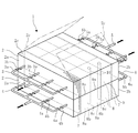
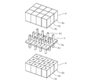
- FIG. 1 to 3 show an example of the form of a gas concentrating device according to an embodiment of the present invention
- FIG. 4 shows a gas concentrating system by a pressure fluctuation adsorption method to which the gas concentrating device according to the embodiment of the present invention is applied. An example is shown.
- the gas concentrator 1 of this embodiment is characterized in that a plurality of adsorption tanks 2 configured in a rectangular parallelepiped shape are stacked one above the other.
- adsorption tank 2 configured in a rectangular parallelepiped shape
- positions so that adsorption tank 2 may be stacked in two steps is illustrated.
- an inlet pipe 3 or an inlet pipe 4 as an introduction channel for introducing gas into the inside along the horizontal direction from one side surface 2 a of the adsorption tank 2, and the gas inside the adsorption tank 2 are supplied.
- An outlet pipe 5 or an outlet pipe 6 serving as a lead-out flow path led out from the other side surface 2b along the horizontal direction is connected to each other.
- the gas introduced into the adsorption tank 2 is circulated along the horizontal direction in the adsorption tank 2.
- the direction along the horizontal direction indicates not only the exact horizontal direction but also the substantially horizontal direction including the direction slightly inclined from the horizontal direction.
- the inlet pipes 3 and 4 extend from the outside of the respective adsorption tanks 2 toward the respective adsorption tanks 2 and are connected to the one side surface 2a so as to be branched in front of the one side surface 2a. In this way, gas is introduced into the upper and lower adsorption tanks 2 from the plurality of branch pipes 3a or 4a. Further, the outlet pipes 5 and 6 lead out gas from a plurality of branch pipes 5a or branch pipes 6a projecting to the other side surface 2b of each adsorption tank 2, merge on the downstream side, and further extend downstream. Yes.
- the branch pipes 3a and 4a of the inlet pipes 3 and 4 and the branch pipes 5a and 6a of the outlet pipes 5 and 6 are respectively provided with valves 3b, 4b, 5b, and 6b capable of adjusting the flow rate of the gas flowing inside. Is provided. Although the case where the inlet pipes 3 and 4 and the outlet pipes 5 and 6 are branched into four branch pipes 3a, 4a, 5a, and 6a is illustrated here, the number and arrangement of the branches can be changed as appropriate. .
- a dispersion plate 7 is installed at a position facing the side surface 2a on one side and a position facing the side surface 2b on the other side.
- An adsorbent 8 a is accommodated between the two dispersion plates 7 to constitute an adsorbent layer 8.
- Each dispersion plate 7 is a punching metal in which a large number of holes are opened, and is arranged separately from the side surface 2a on one side and the side surface 2b on the other side.
- the gas introduced from the side surface 2a on the one side through the branch pipes 3a and 4a of the inlet pipes 3 and 4 is dispersed from the space between the side surface 2a on the one side and the dispersion plate 7 on the inlet side.
- adsorbent 8a various materials such as synthetic zeolite and molecular sieve can be used.
- an adsorbent 8a composed of a metal-organic structure (MOF) particularly suitable for carbon dioxide adsorption is employed.
- the adsorbent 8a adsorbs carbon dioxide in the gas under an adsorption pressure higher than atmospheric pressure, and desorbs the adsorbed carbon dioxide under a desorption pressure near atmospheric pressure lower than the adsorption pressure.
- adsorption pressure refers to a pressure at which the adsorbent 8a can adsorb a specific adsorbing component.
- the “desorption pressure” is a pressure lower than the adsorption pressure and refers to a pressure at which the adsorption component adsorbed by the adsorbent 8a can be desorbed.
- the adsorbent layer 8 is configured as an aggregate of a plurality of adsorbent units 8b.
- Each adsorbent unit 8b is formed by filling an adsorbent 8a in a rectangular parallelepiped casing 8c made of a material such as a mesh through which gas passes.
- a plurality of adsorbent units 8b are arranged in the horizontal direction to form an adsorbent layer 8.
- the adsorbent layer 8 is divided into a plurality of adsorbent units 8b by the housing 8c. And the division
- segmentation position of the adsorption agent layer 8 in the upper and lower adsorption tank 2 corresponds in planar view as shown in FIG. 2, FIG.
- the upper and lower adsorption tanks 2 are separated by a partition plate 9 that forms a surface along the horizontal direction.
- the adsorbent layers 8 in the upper and lower adsorption tanks 2 are in contact with each other through a partition plate 9.
- a heat transfer body 10 extending along the vertical direction is provided so as to penetrate the partition plate 9 up and down. In FIG. 1, only a part of the heat transfer body 10 is shown for convenience of illustration.
- the heat transfer body 10 is an object in which, for example, a metal is formed into a hollow rod shape, and a heat medium such as water or an organic solvent is enclosed therein.
- the heat transfer body 10 is installed in such a manner that the upper part is buried in the adsorbent layer 8 of the upper adsorption tank 2 and the lower part is buried in the adsorbent layer 8 of the lower adsorption tank 2.
- the heat transfer body 10 connects the upper and lower adsorbent layers 8 to each other so as to quickly transfer the heat generated in the adsorbent layer 8 of one adsorption tank 2 to the adsorbent layer 8 of the other adsorption tank 2. It has become.
- the heat transfer body 10 is not limited to the above-described configuration, and can take various shapes or structures.
- it can be made of a solid metal that does not enclose a heating medium or the like, and the shape can also be, for example, a plate-like object other than a rod shape.
- the partition plate 9 is made of a material such as a metal having high thermal conductivity, and is divided into a plurality of small partition plates 9a. As shown in FIG. 3, the division position of the partition plate 9 into the small partition plates 9a coincides with the division position of the adsorbent layer 8 positioned above and below the partition plate 9 in plan view. That is, one adsorbent unit 8b is arranged above and below each small partition plate 9a. Further, the partition plate 9 includes one heat transfer body 10 for each small partition plate 9a. The small partition plates 9a are sealed with a sealing material (not shown) so as to maintain airtightness.
- each heat transfer body 10 can be increased or decreased depending on the thermal conductivity of the heat transfer bodies 10, the amount of heat expected to be generated in the adsorption process described later, and other conditions.
- each heat transfer body 10 is arranged in the center of each adsorbent unit 8b in plan view, but this arrangement can be changed as appropriate.
- each heat transfer body 10 may be positioned between the adsorbent units 8b.
- each adsorbent layer 8 and the partition plate 9 are divided into 12 adsorbent units 8b and small partition plates 9a, respectively, is illustrated, but the number of divisions and the adsorbent units 8b or small partitions are also illustrated.
- the shape of the plate 9a can be changed as appropriate.
- the upper surface of the upper adsorption tank 2 is configured as a lid 2c that can be opened and closed in the vertical direction. Then, the lid 2c is opened as necessary, and the adsorbent layer 8, the dispersion plate 7, the partition plate 9 and the like accommodated in the internal space can be accessed.
- the lid 2c is not limited to the method of opening and closing as shown in the drawing, and may be configured to open and close by sliding in the horizontal direction, for example.
- the opening / closing structure of the adsorption tank 2 may be any configuration.
- FIG. 4 shows an example of a gas concentration system to which the gas concentrator 1 as described above is applied.
- the mixed gas G ⁇ b> 1 that is exhaust gas discharged from a combustion boiler (not shown) and includes a plurality of types of gases is cooled by the cooler 11.
- the mixed gas G1 which is an exhaust gas, is generally at a high temperature of about several hundred degrees C.
- the temperature suitable for adsorption of a specific gas for the adsorbent 8a is about room temperature to several tens of degrees C. For this reason, the temperature of the mixed gas G1 is previously reduced here.
- the volume of the mixed gas G1 also decreases with cooling, there is also an advantage that the processing efficiency in the gas concentrator 1 and other facilities is improved.
- the mixed gas G1 is pressurized by the compressor 12 and further sent to the dehydration tower 13 to remove moisture.
- the dehydrating tower 13 is filled with a dehydrating agent such as silica gel, and moisture is adsorbed and removed by passing the mixed gas G1 through the dehydrating agent.
- the mixed gas G1 is exhaust gas from a coal fired boiler or the like, illustration is omitted, but before and after the cooler 11, the compressor 12, the dehydration tower 13, and the like, a gas-liquid separator, a desulfurization device, and a denitration device.
- Various equipment such as mercury removal equipment is installed as appropriate. This is to prevent corrosion and performance deterioration of the equipment including the gas concentrator 1 and to increase the purity of carbon dioxide finally separated.
- the mixed gas G1 from which moisture has been removed is then sent to the adsorption tank 2 of the gas concentrator 1.
- the flow path 14 of the mixed gas G1 branches into an inlet pipe 3 of the upper adsorption tank 2 and an inlet pipe 4 of the lower adsorption tank 2.
- a three-way valve 15 as a flow path switch is provided at a branch point to the upper and lower inlet pipes 3 and 4. The three-way valve 15 can be switched between an inlet pipe 3 leading to the upper adsorption tank 2 where the mixed gas G1 is introduced and an inlet pipe 4 leading to the lower adsorption tank 2.
- outlet pipe 5 of the upper adsorption tank 2 and the outlet pipe 6 of the lower adsorption tank 2 are branched into the flow paths 16 and 17 and the flow paths 18 and 19, respectively, downstream of both adsorption tanks 2.
- the flow path 16 branched from the outlet pipe 5 merges with the flow path 18 branched from the outlet pipe 6 and continues to the flow path 20.
- a three-way valve 21 as a flow path switching device is provided at a junction point from the flow paths 16 and 18 to the flow path 20.
- the flow path 17 branched from the outlet pipe 5 joins with the flow path 19 branched from the outlet pipe 6 and continues to the flow path 22.
- a three-way valve 23 as a flow path switching device is provided at a junction point from the flow paths 17 and 19 to the flow path 22.
- carbon dioxide as an adsorbed component G2 selectively extracted from the mixed gas G1 is discharged from the flow path 20 and sent to a compression facility, a storage facility, or the like (not shown).
- the non-adsorbed component G3 after the adsorbed component G2 is extracted from the mixed gas G1 is discharged from the flow path 22 as will be described later.
- the non-adsorbed portion G3 is heated by the heater 24 and then sent to the dehydrating tower 13.
- the non-adsorbed component G3 is used for regeneration of the dehydrating agent in the dehydrating tower 13 and is diffused into the atmosphere together with water vapor. That is, the dehydrating agent filled in the dehydrating tower 13 is silica gel or the like, and the adsorbed moisture is released by heating, and the function as the dehydrating agent can be recovered.
- the heater 24 may be, for example, an apparatus that electrically heats the non-adsorption component G3.
- the heater 24 is provided as a heat exchanger that is provided in any part that requires cooling of the mixed gas G1 in the processing path of the mixed gas G1, and that heats the non-adsorbed component G3 while cooling the mixed gas G1. May be.
- the flow path 22 is provided with a concentration sensor 25 for detecting the concentration of the component corresponding to the adsorbed component G2 out of the non-adsorbed component G3 discharged from the flow path 22.
- a specific component in this case, carbon dioxide
- the adsorption tank 2 a specific component (in this case, carbon dioxide) is adsorbed as the adsorption component G2 as described above.
- the adsorbed component G2 contained in the mixed gas G1 can be removed, and a part of the adsorbed component G2 is discharged as a part of the non-adsorbed part G3 without being adsorbed.
- the amount of adsorption of the adsorbing component G2 in the adsorbent layer 8 is also limited.
- the concentration sensor 25 detects and monitors the concentration of the adsorption component G2 equivalent component.
- the mixed gas G1 which is exhaust gas, is cooled by the cooler 11, pressurized by the compressor 12, and after moisture is removed by the dehydration tower 13, it is sent to the gas concentrator 1 (see FIG. 4). At this time, the pressurized mixed gas G1 is introduced into one of the adsorption tanks 2 installed in two upper and lower stages. By operating the three-way valve 15, the inlet pipe 3 that is an introduction flow path leading to the upper adsorption tank 2 is opened, and the inlet pipe 4 leading to the lower adsorption tank 2 is closed. The mixed gas G1 flows from the flow path 14 into the upper adsorption tank 2 through the inlet pipe 3.
- the pressure of the pressurized mixed gas G1 is set to an adsorption pressure at which the adsorbent 8a (see FIG. 1) filled in the adsorption tank 2 can adsorb carbon dioxide as the adsorption component G2. Therefore, in the upper adsorption tank 2, an adsorbing step is performed in which the carbon dioxide in the mixed gas G1 is adsorbed on the adsorbent layer 8 as the adsorbing component G2 when the mixed gas G1 flows in. Then, the remaining non-adsorbed portion G3 that adsorbs carbon dioxide from the mixed gas G1 is discharged from the outlet pipe 5 connected to the upper adsorption tank 2.
- the three-way valve 21 closes the space between the flow path 16 leading to the upper adsorption tank 2 and the downstream flow path 20.
- the three-way valve 23 opens between the flow path 17 leading to the upper adsorption tank 2 and the downstream flow path 22, and between the flow path 19 leading to the lower adsorption tank 2 and the downstream flow path 22. Occlude. In this way, the non-adsorption portion G3 flowing out from the outlet pipe 5 of the upper adsorption tank 2 is discharged from the flow path 17 to the flow path 22.
- the concentration sensor 25 provided in the flow path 22 monitors the concentration of carbon dioxide in the non-adsorbed component G3.
- the amount of carbon dioxide adsorbed in the adsorbent layer 8 in the upper adsorbing tank 2 increases and approaches the maximum amount that can be adsorbed by the adsorbent layer 8, the amount of carbon dioxide in the non-adsorbed portion G 3 is accordingly increased. Pressure rises. Therefore, the three-way valves 15, 21, 23 are switched when the partial pressure of carbon dioxide detected by the concentration sensor 25 increases to some extent.
- the adsorption process is performed in the upper adsorption tank 2, but next, the adsorption process is performed in the lower adsorption tank 2, and the desorption process is performed in the upper adsorption tank 2. .
- the three-way valve 15 switches between closing the flow path 14 and the inlet pipe 3 and opening between the flow path 14 and the inlet pipe 4. Further, the three-way valve 21 switches between the flow path 16 and the flow path 20 and closes between the flow path 18 and the flow path 20. The three-way valve 23 switches between the flow path 17 and the flow path 22 and opens between the flow path 19 and the flow path 22.
- the mixed gas G1 supplied at the adsorption pressure from the flow path 14 flows into the lower adsorption tank 2 from the lower inlet pipe 4, and here, carbon dioxide as the adsorbed component G2 is introduced into the adsorbent layer 8.
- An adsorption process for adsorption is performed.
- the remaining non-adsorbed portion G3 is discharged from the lower outlet pipe 6 to the flow path 22 via the flow path 19.
- the path from the outlet pipe 5 to the flow path 20 via the flow path 16 is opened, so that the internal pressure drops to a desorption pressure near atmospheric pressure.
- the desorption process in which the carbon dioxide as the adsorption component G2 adsorbed on the adsorbent layer 8 is desorbed is executed.
- the desorbed carbon dioxide is discharged from the outlet pipe 5 to the flow path 20 via the flow path 16 and sent to a compression facility or storage facility (not shown) in the subsequent stage.
- the concentration sensor 25 monitors the carbon dioxide concentration in the non-adsorption component G3. If the concentration rises to some extent, it is determined that the amount of carbon dioxide adsorbed in the adsorbent layer 8 of the lower adsorption tank 2 has approached the maximum value, and the three-way valves 15, 21, 23 are switched again. In the upper adsorption tank 2, carbon dioxide is desorbed from the adsorbent layer 8 by the preceding desorption process. Therefore, if the pressurized mixed gas G1 is introduced from the flow path 14 through the inlet pipe 3, the adsorption step can be executed again.
- the non-adsorbed component G3 is discharged from the outlet pipe 5 to the flow path 22 via the flow path 17.
- the path from the outlet pipe 6 to the flow path 20 via the flow path 18 is opened, and the pressure drops to the desorption pressure.
- the carbon dioxide as the adsorbing component G2 adsorbed in the preceding adsorption step is desorbed and discharged to the flow path 20.
- the adsorption / desorption process and the adsorption process are alternately repeated between the adsorption tanks 2 stacked in the upper and lower stages, so that the adsorption component G2 is continuously obtained from the mixed gas G1.
- Of carbon dioxide can be separated.
- the gas concentration process itself by the pressure fluctuation adsorption method is the same as that of the conventional gas concentration apparatus.
- the gas flow in the adsorption tank 2 is not horizontal but horizontal.
- the orientation is set along the direction. Thereby, the increase in the cost concerning construction is suppressed, securing a large capacity about adsorption tank 2.
- the distance for adsorption may be ensured along the horizontal direction. Therefore, it is possible to suppress the height of the adsorption tank 2, reduce the weight per unit area, and greatly reduce the cost for installing the foundation.
- the problem of the heat accompanying the enlargement of the adsorption tank 2 is dealt with by equalizing the gas flow in the adsorption tank 2 or installing the heat transfer body 10. I have to.
- heat is generated when gas is adsorbed to the adsorbent layer 8. This heat is not always generated uniformly throughout the adsorbent layer 8.
- the generation of heat is biased, and a specific part in the adsorbent layer 8 is localized. In some cases, a large amount of heat is generated.
- Such a bias in heat generation is more likely to occur as the volume of the adsorbent layer 8 increases. Further, if the volume of the adsorbent layer 8 and the amount of gas flowing into the adsorbent layer 8 are large, the total amount of heat generated is also large, and the influence of heat generation bias can be large.
- the flow of the mixed gas G1 flowing through the adsorption tank 2 is made uniform to some extent by the configuration of the dispersion plate 7 and the branch pipes 3a, 4a, 5a, 6a branched into a plurality of branches. (See FIGS. 1 and 2).
- Each branch pipe 3a, 4a, 5a, 6a is provided with valves 3b, 4b, 5b, 6b, respectively. Therefore, by finely adjusting the opening degree of each valve 3b, 4b, 5b, 6b, the flow rate of the gas flowing through the branch pipes 3a, 4a, 5a, 6a is manipulated, and the gas flow in the adsorption tank 2 is controlled. It is also possible to correct it.
- the adsorbent layers 8 filled in the upper and lower adsorption tanks 2 are connected by the heat transfer body 10 as described above (see FIGS. 1 to 3).
- the heat transfer body 10 can quickly transfer the heat generated in the adsorbent layer 8 of one adsorption tank 2 to the adsorbent layer 8 of the other adsorption tank 2. Therefore, even if heat of adsorption is generated in one of the adsorption tanks 2 in the adsorption process, and the temperature starts to rise locally in the adsorbent layer 8, the heat is transferred to the heat transfer body. 10 can be quickly released to the other adsorption tank 2 side in the desorption process.
- the heat transfer is also performed through the partition plate 9 that separates the upper and lower adsorbent layers 8 from each other.
- a large contact area through the partition plate 9 is ensured by a configuration in which the adsorption tanks 2 are stacked. It is also possible to arrange the two adsorption tanks so as to contact each other via a partition plate, for example, by arranging the two adsorption tanks on the left and right. However, if an attempt is made to increase the contact area between the adsorption tanks in such an arrangement, the height of the adsorption tanks must be increased. If it is going to enlarge an adsorption tank in such a shape, the construction cost concerning a foundation will be unavoidable. In that respect, if it is arrangement
- an adsorbent used in a pressure fluctuation adsorption type gas concentrator is gradually reduced in adsorption capacity during repeated adsorption and desorption, and therefore needs to be replaced every several years.
- an adsorbent replacement operation has been performed manually by a person entering a cylindrical adsorption tank.
- the capacity of the adsorption tank is large and a large amount of adsorbent is filled, such manual replacement is difficult, and it takes time and money.
- the lid 2c is provided on the upper surface of the upper adsorption tank 2 as described above (see FIG. 1). By opening the lid 2c, the internal adsorbent layer 8 and the like can be accessed from above.
- the adsorbent layer 8 is configured as a set of adsorbent units 8b in which the adsorbent 8a is accommodated in the housing 8c. Therefore, for example, by suspending the adsorbent unit 8b from above using a crane, the exchanging operation of the adsorbent unit 8b can be performed without depending on human power.
- the arrangement in which the adsorption tanks 2 are stacked one above the other is advantageous in this replacement operation.
- the partition plate is arranged so as to form a surface along the vertical direction.
- the heat transfer body which connects adsorbent layers in an adsorption tank is provided along a horizontal direction so that this partition plate may be penetrated. For this reason, when trying to move the adsorbent unit in the vertical direction, the heat transfer body becomes an obstacle.
- the heat transfer body 10 is arranged along the vertical direction as shown in FIGS.
- the heat transfer body 10 does not interfere with the operation of the adsorbent unit 8b. Therefore, for example, the following procedure can be executed smoothly. 1) The upper adsorbent unit 8b is lifted in the vertical direction and moved out of the adsorption tank 2. 2) The small partition plate 9a located therebelow is lifted and removed together with the heat transfer body 10 in the vertical direction. 3) The adsorbent unit 8b located below is moved.
- the division position of the upper and lower adsorbent layers 8 and the division position of the partition plate 9 coincide in plan view. Therefore, for example, after the upper adsorbent unit 8b is taken out, another adsorbent unit 8b may become a hindrance when trying to take out the small partition plate 9a or the adsorbent unit 8b located therebelow. Absent. Alternatively, the upper and lower two adsorbent units 8b and the small partition plate 9a disposed therebetween can be lifted together.
- the mixed gas G1 is introduced into the interior, and the adsorbing tank 2 is circulated along the horizontal direction, and the adsorbing tank 2 accommodates the mixed gas G1 in the adsorbing tank 2.
- a part of the gas in the mixed gas G1 is adsorbed as an adsorbed component G2, and adsorbed when the inside of the adsorption tank 2 is depressurized to a desorption pressure lower than the adsorption pressure.
- the pressure fluctuation adsorption type gas concentrating device 1 when the pressure fluctuation adsorption type gas concentrating device 1 is installed, the gas flowing distance in the adsorbent layer 8 can be secured along the horizontal direction. Moreover, the construction cost concerning a foundation can be reduced by suppressing the height of the adsorption tank 2.
- a plurality of the adsorption tanks 2 are arranged close to each other, and the adsorbent layers 8 in the plurality of adsorption tanks 2 are connected to each other by a heat transfer body 10 that transfers heat. .
- the heat of adsorption generated in one adsorption tank 2 in the adsorption process can be released to the other adsorption tank 2 in the desorption process via the heat transfer body 10, and the adsorbent layer 8 in the adsorption process. High temperature can be avoided. Further, the heat of adsorption generated in one adsorption tank 2 can be used for the progress of desorption in the other adsorption tank 2.
- the adsorption tank 2 is arranged so as to be stacked up and down, and the adsorbent layers 8 in the adsorption tank 2 arranged up and down are in contact with each other through a partition plate 9.
- the heat of adsorption generated in one adsorption tank 2 in the adsorption process can be released to the other adsorption tank 2 in the desorption process via the partition plate 9 and the production of the adsorption tank 2 is involved. Material costs can be saved.
- the adsorbent layer 8 is divided into a plurality of adsorbent units 8b each having an adsorbent 8a, and the partition plate 9 is divided into a plurality of small partition plates 9a.
- the upper surface of the adsorption tank 2 of the adsorption tank 2 disposed in the upper part of the adsorption tank 2 is configured to be accessible from the outside to the internal space. By doing so, the replacement work of the adsorbent 8a and the like can be executed using a crane or the like.
- the division position of the adsorbent layer 8 in the adsorption tank 2 arranged above and below into the adsorbent unit 8b and the division position of the partition plate 9 into the small partition plate 9a. are consistent in plan view. By doing so, the replacement work of the adsorbent 8a using a crane or the like can be executed more easily.
- the gas concentrator of this indication is not limited only to the above-mentioned Example.
- the present invention can be applied to separation of gas from exhaust gas of various boilers in addition to coal fired boilers including oxyfuel boilers. Further, the present invention can be applied not only to separation of carbon dioxide from exhaust gas but also to extraction of gas from various mixed gases.
- various changes can be made without departing from the scope of the present disclosure.
Landscapes
- Chemical & Material Sciences (AREA)
- Engineering & Computer Science (AREA)
- Analytical Chemistry (AREA)
- General Chemical & Material Sciences (AREA)
- Oil, Petroleum & Natural Gas (AREA)
- Chemical Kinetics & Catalysis (AREA)
- Environmental & Geological Engineering (AREA)
- Health & Medical Sciences (AREA)
- Biomedical Technology (AREA)
- Separation Of Gases By Adsorption (AREA)
- Treating Waste Gases (AREA)
Abstract
Description
2 吸着槽
8 吸着剤層
8a 吸着剤
8b 吸着剤ユニット
9 仕切板
9a 小仕切板
10 伝熱体
G1 混合ガス
G2 吸着成分
Claims (8)
- 複数の種類の気体が混合した混合ガスを内部に導入し、水平方向に沿って流通させる吸着槽と、
該吸着槽に収容され、該吸着槽に混合ガスが吸着圧にて導入された場合に前記混合ガス中の一部の気体を吸着成分として吸着し、且つ前記吸着槽内が前記吸着圧より低い脱着圧に減圧された場合に、吸着した前記吸着成分を脱着する吸着剤層と
を備えた圧力変動吸着式の気体濃縮装置。 - 複数の前記吸着槽が近接して配置され、前記複数の吸着槽内の前記吸着剤層同士は熱を伝達する伝熱体により互いに連結されている、請求項1に記載の気体濃縮装置。
- 前記吸着槽は上下に積み重ねるように配置され、上下に配置された前記吸着槽内の前記吸着剤層同士は、仕切板を介して接している、請求項2に記載の気体濃縮装置。
- 前記吸着剤層は、吸着剤を備えた複数の吸着剤ユニットに分割され、
前記仕切板は、複数の小仕切板に分割されており、
互いに上下に配置された前記吸着槽のうち、上側の吸着槽の上面は、該吸着槽の外部から内部の空間へアクセス可能に構成されている、請求項3に記載の気体濃縮装置。 - 上下に配置された前記吸着槽内の前記吸着剤層における前記吸着剤ユニットへの分割位置、及び、前記仕切板における前記小仕切板への分割位置は平面視で一致している、請求項4に記載の気体濃縮装置。
- 前記吸着槽は上下に積み重ねるように配置され、上下に配置された前記吸着槽内の前記吸着剤層同士は、仕切板を介して接している、請求項1に記載の気体濃縮装置。
- 前記吸着剤層は、吸着剤を備えた複数の吸着剤ユニットに分割され、
前記仕切板は、複数の小仕切板に分割されており、
互いに上下に配置された前記吸着槽のうち、上側の吸着槽の上面は、該吸着槽の外部から内部の空間へアクセス可能に構成されている、請求項6に記載の気体濃縮装置。 - 上下に配置された前記吸着槽内の前記吸着剤層における前記吸着剤ユニットへの分割位置、及び、前記仕切板における前記小仕切板への分割位置は平面視で一致している、請求項7に記載の気体濃縮装置。
Priority Applications (3)
| Application Number | Priority Date | Filing Date | Title |
|---|---|---|---|
| AU2017373170A AU2017373170B2 (en) | 2016-12-05 | 2017-09-15 | Gas concentrator |
| CA3033468A CA3033468A1 (en) | 2016-12-05 | 2017-09-15 | Gas concentrator |
| US16/429,821 US11148093B2 (en) | 2016-12-05 | 2019-06-03 | Gas concentrator |
Applications Claiming Priority (2)
| Application Number | Priority Date | Filing Date | Title |
|---|---|---|---|
| JP2016235501A JP6805770B2 (ja) | 2016-12-05 | 2016-12-05 | 気体濃縮装置 |
| JP2016-235501 | 2016-12-05 |
Related Child Applications (1)
| Application Number | Title | Priority Date | Filing Date |
|---|---|---|---|
| US16/429,821 Continuation US11148093B2 (en) | 2016-12-05 | 2019-06-03 | Gas concentrator |
Publications (1)
| Publication Number | Publication Date |
|---|---|
| WO2018105196A1 true WO2018105196A1 (ja) | 2018-06-14 |
Family
ID=62491846
Family Applications (1)
| Application Number | Title | Priority Date | Filing Date |
|---|---|---|---|
| PCT/JP2017/033484 Ceased WO2018105196A1 (ja) | 2016-12-05 | 2017-09-15 | 気体濃縮装置 |
Country Status (5)
| Country | Link |
|---|---|
| US (1) | US11148093B2 (ja) |
| JP (1) | JP6805770B2 (ja) |
| AU (1) | AU2017373170B2 (ja) |
| CA (1) | CA3033468A1 (ja) |
| WO (1) | WO2018105196A1 (ja) |
Cited By (2)
| Publication number | Priority date | Publication date | Assignee | Title |
|---|---|---|---|---|
| RU217089U1 (ru) * | 2022-10-27 | 2023-03-16 | Акционерное общество "Научно- исследовательский институт "Полюс" им. М.Ф. Стельмаха" | Концентратор кислорода |
| WO2023210797A1 (ja) * | 2022-04-28 | 2023-11-02 | 株式会社Atomis | ガスの回収装置及び回収方法 |
Families Citing this family (9)
| Publication number | Priority date | Publication date | Assignee | Title |
|---|---|---|---|---|
| FR3078635B1 (fr) * | 2018-03-09 | 2022-05-06 | Air Liquide | Adsorbeur avec au moins une grappe de plusieurs modules d'adsorbant |
| FR3093009B1 (fr) * | 2019-02-21 | 2021-07-23 | Air Liquide | Procédé et installation de purification d’un flux gazeux de débit élevé |
| JP6885983B2 (ja) * | 2019-04-08 | 2021-06-16 | メタウォーター株式会社 | 配管ユニット |
| JP7716237B2 (ja) * | 2021-06-09 | 2025-07-31 | 株式会社豊田中央研究所 | 二酸化炭素回収装置 |
| CN119730940A (zh) * | 2022-09-01 | 2025-03-28 | 日本碍子株式会社 | 酸性气体吸附装置 |
| WO2024048578A1 (ja) * | 2022-09-01 | 2024-03-07 | 日本碍子株式会社 | 酸性ガス吸着装置 |
| JP7571097B2 (ja) * | 2022-09-29 | 2024-10-22 | 本田技研工業株式会社 | 二酸化炭素除去装置 |
| IT202300003402A1 (it) * | 2023-02-27 | 2024-08-27 | Synecom S R L | Dispositivo di ricircolo e deumidificazione di gas fluorati |
| WO2026062923A1 (ja) * | 2024-09-18 | 2026-03-26 | 三菱電機株式会社 | ガス回収装置 |
Citations (6)
| Publication number | Priority date | Publication date | Assignee | Title |
|---|---|---|---|---|
| JPS5011864B1 (ja) * | 1970-10-30 | 1975-05-07 | ||
| JPS52138060A (en) * | 1976-04-19 | 1977-11-17 | Mitsui Toatsu Chem Inc | Adsorption apparatus |
| JPS5592122A (en) * | 1978-12-28 | 1980-07-12 | Daido Steel Co Ltd | Method and apparatus for adsorption |
| JPS62210031A (ja) * | 1986-02-26 | 1987-09-16 | Mitsubishi Electric Corp | ガス処理装置 |
| JPH01297118A (ja) * | 1988-05-25 | 1989-11-30 | Hitachi Ltd | Psa方式の吸着塔構造 |
| WO2000059610A1 (en) * | 1999-03-30 | 2000-10-12 | Kuraray Chemical Co., Ltd. | Mixed gas separating method and separating apparatus |
Family Cites Families (14)
| Publication number | Priority date | Publication date | Assignee | Title |
|---|---|---|---|---|
| US2586670A (en) * | 1945-01-31 | 1952-02-19 | Christian J Lambertsen | Selective gas adsorber |
| US3948775A (en) * | 1972-06-07 | 1976-04-06 | Toray Industries, Inc. | Horizontal packed column consisting of multiple chambers with fluid distributors |
| JPS5011864A (ja) | 1973-05-29 | 1975-02-06 | ||
| US4026680A (en) * | 1974-10-30 | 1977-05-31 | Union Carbide Corporation | Air separation by adsorption |
| JPS5953201B2 (ja) * | 1979-12-18 | 1984-12-24 | 松下電器産業株式会社 | 水素ガスの精製方法 |
| US4826510A (en) * | 1988-01-13 | 1989-05-02 | The John Bunn Company | Portable low profile DC oxygen concentrator |
| JPH0429712A (ja) | 1990-05-25 | 1992-01-31 | Matsushita Electric Works Ltd | ガス濃縮装置 |
| JP3070298B2 (ja) | 1992-09-16 | 2000-07-31 | 日本軽金属株式会社 | アルミニウム材料の塗装方法 |
| JPH0852317A (ja) | 1994-08-11 | 1996-02-27 | Showa Eng Kk | 安定した圧力変動吸着法 |
| US5672196A (en) * | 1995-08-01 | 1997-09-30 | The Boc Group, Inc. | Process and apparatus for the separation of gases |
| US6878186B2 (en) * | 2003-09-09 | 2005-04-12 | David Lloyd Neary | Pure vacuum swing adsorption system and apparatus |
| GB2511357A (en) * | 2013-03-01 | 2014-09-03 | Walker Filtration Ltd | Banked purification system |
| JP5875548B2 (ja) | 2013-03-28 | 2016-03-02 | Jfeスチール株式会社 | ガス分離方法 |
| US9358496B2 (en) * | 2013-07-03 | 2016-06-07 | Praxair Technology, Inc. | Adsorption bed structure and process |
-
2016
- 2016-12-05 JP JP2016235501A patent/JP6805770B2/ja active Active
-
2017
- 2017-09-15 AU AU2017373170A patent/AU2017373170B2/en active Active
- 2017-09-15 CA CA3033468A patent/CA3033468A1/en not_active Abandoned
- 2017-09-15 WO PCT/JP2017/033484 patent/WO2018105196A1/ja not_active Ceased
-
2019
- 2019-06-03 US US16/429,821 patent/US11148093B2/en active Active
Patent Citations (6)
| Publication number | Priority date | Publication date | Assignee | Title |
|---|---|---|---|---|
| JPS5011864B1 (ja) * | 1970-10-30 | 1975-05-07 | ||
| JPS52138060A (en) * | 1976-04-19 | 1977-11-17 | Mitsui Toatsu Chem Inc | Adsorption apparatus |
| JPS5592122A (en) * | 1978-12-28 | 1980-07-12 | Daido Steel Co Ltd | Method and apparatus for adsorption |
| JPS62210031A (ja) * | 1986-02-26 | 1987-09-16 | Mitsubishi Electric Corp | ガス処理装置 |
| JPH01297118A (ja) * | 1988-05-25 | 1989-11-30 | Hitachi Ltd | Psa方式の吸着塔構造 |
| WO2000059610A1 (en) * | 1999-03-30 | 2000-10-12 | Kuraray Chemical Co., Ltd. | Mixed gas separating method and separating apparatus |
Cited By (2)
| Publication number | Priority date | Publication date | Assignee | Title |
|---|---|---|---|---|
| WO2023210797A1 (ja) * | 2022-04-28 | 2023-11-02 | 株式会社Atomis | ガスの回収装置及び回収方法 |
| RU217089U1 (ru) * | 2022-10-27 | 2023-03-16 | Акционерное общество "Научно- исследовательский институт "Полюс" им. М.Ф. Стельмаха" | Концентратор кислорода |
Also Published As
| Publication number | Publication date |
|---|---|
| AU2017373170A1 (en) | 2019-03-07 |
| JP2018089581A (ja) | 2018-06-14 |
| CA3033468A1 (en) | 2018-06-14 |
| JP6805770B2 (ja) | 2020-12-23 |
| US11148093B2 (en) | 2021-10-19 |
| US20190282950A1 (en) | 2019-09-19 |
| AU2017373170B2 (en) | 2019-12-19 |
Similar Documents
| Publication | Publication Date | Title |
|---|---|---|
| WO2018105196A1 (ja) | 気体濃縮装置 | |
| JP7491944B2 (ja) | 空気からco2を回収する高スループット直接空気回収デバイス及びその動作方法 | |
| KR102137788B1 (ko) | 이산화탄소 포획/재생 구조체 및 기술 | |
| US11285438B2 (en) | Carbon dioxide separation recovery system and method | |
| US9144766B2 (en) | Method and apparatus for rapid adsorption-desorption CO2 capture | |
| US8894753B2 (en) | Carbon dioxide capture systems | |
| BR112016015436B1 (pt) | Sistema de movimento rotativo de leitos multimonolíticos para a remoção de co2 da atmosfera | |
| JP5269426B2 (ja) | 水素生成システム | |
| JPWO2009069772A1 (ja) | オゾン濃縮装置 | |
| CN110124443B (zh) | 一种有机废气回收再利用装置及方法 | |
| CN117225141A (zh) | 二氧化碳捕集装置及其工作方法 | |
| US20250161870A1 (en) | Mechanical vapor re-compressor heat pump for separating co2 from water vapor in temperature-vacuum swing adsorption cycles | |
| KR20220085903A (ko) | 판형 열교환기를 이용한 건식 이산화탄소 포집장치 및 이를 이용한 건식 이산화탄소 포집공정 | |
| JPH0885892A (ja) | 酸素・水素発生装置 | |
| CN118594242A (zh) | 一种n+m级固体床固体吸附co2捕集系统及运行方法 | |
| JP2005103335A (ja) | 熱脱着式酸素濃縮装置 | |
| CN119451737A (zh) | 二氧化碳回收系统 | |
| CN211706343U (zh) | 一种新型VOCs气体回收处理装置 | |
| JP2005032697A (ja) | 燃料電池システムの残留物除去装置及び方法 | |
| CN215352848U (zh) | 一种储罐油气VOCs回收处理系统 | |
| JP2014188507A (ja) | 吸着塔およびガス分離装置 | |
| KR101071865B1 (ko) | 높은 에너지 효율과 무탄소방식의 흡착식 제습시스템 | |
| JP3265219B2 (ja) | 排気処理装置 | |
| WO2026055664A1 (en) | Carbon dioxide capture and separation system utilizing heat pumps for thermal recuperation and steam generation |
Legal Events
| Date | Code | Title | Description |
|---|---|---|---|
| 121 | Ep: the epo has been informed by wipo that ep was designated in this application |
Ref document number: 17878395 Country of ref document: EP Kind code of ref document: A1 |
|
| ENP | Entry into the national phase |
Ref document number: 3033468 Country of ref document: CA |
|
| ENP | Entry into the national phase |
Ref document number: 2017373170 Country of ref document: AU Date of ref document: 20170915 Kind code of ref document: A |
|
| NENP | Non-entry into the national phase |
Ref country code: DE |
|
| 122 | Ep: pct application non-entry in european phase |
Ref document number: 17878395 Country of ref document: EP Kind code of ref document: A1 |