WO2018105155A1 - 双極板、セルスタック、及びレドックスフロー電池 - Google Patents
双極板、セルスタック、及びレドックスフロー電池 Download PDFInfo
- Publication number
- WO2018105155A1 WO2018105155A1 PCT/JP2017/022929 JP2017022929W WO2018105155A1 WO 2018105155 A1 WO2018105155 A1 WO 2018105155A1 JP 2017022929 W JP2017022929 W JP 2017022929W WO 2018105155 A1 WO2018105155 A1 WO 2018105155A1
- Authority
- WO
- WIPO (PCT)
- Prior art keywords
- bipolar plate
- groove
- grooves
- discharge
- inclined groove
- Prior art date
Links
Images


Classifications
-
- H—ELECTRICITY
- H01—ELECTRIC ELEMENTS
- H01M—PROCESSES OR MEANS, e.g. BATTERIES, FOR THE DIRECT CONVERSION OF CHEMICAL ENERGY INTO ELECTRICAL ENERGY
- H01M8/00—Fuel cells; Manufacture thereof
- H01M8/02—Details
- H01M8/0202—Collectors; Separators, e.g. bipolar separators; Interconnectors
- H01M8/0258—Collectors; Separators, e.g. bipolar separators; Interconnectors characterised by the configuration of channels, e.g. by the flow field of the reactant or coolant
- H01M8/026—Collectors; Separators, e.g. bipolar separators; Interconnectors characterised by the configuration of channels, e.g. by the flow field of the reactant or coolant characterised by grooves, e.g. their pitch or depth
-
- H—ELECTRICITY
- H01—ELECTRIC ELEMENTS
- H01M—PROCESSES OR MEANS, e.g. BATTERIES, FOR THE DIRECT CONVERSION OF CHEMICAL ENERGY INTO ELECTRICAL ENERGY
- H01M8/00—Fuel cells; Manufacture thereof
- H01M8/04—Auxiliary arrangements, e.g. for control of pressure or for circulation of fluids
- H01M8/04082—Arrangements for control of reactant parameters, e.g. pressure or concentration
- H01M8/04186—Arrangements for control of reactant parameters, e.g. pressure or concentration of liquid-charged or electrolyte-charged reactants
-
- H—ELECTRICITY
- H01—ELECTRIC ELEMENTS
- H01M—PROCESSES OR MEANS, e.g. BATTERIES, FOR THE DIRECT CONVERSION OF CHEMICAL ENERGY INTO ELECTRICAL ENERGY
- H01M8/00—Fuel cells; Manufacture thereof
- H01M8/18—Regenerative fuel cells, e.g. redox flow batteries or secondary fuel cells
- H01M8/184—Regeneration by electrochemical means
- H01M8/188—Regeneration by electrochemical means by recharging of redox couples containing fluids; Redox flow type batteries
-
- H—ELECTRICITY
- H01—ELECTRIC ELEMENTS
- H01M—PROCESSES OR MEANS, e.g. BATTERIES, FOR THE DIRECT CONVERSION OF CHEMICAL ENERGY INTO ELECTRICAL ENERGY
- H01M8/00—Fuel cells; Manufacture thereof
- H01M8/24—Grouping of fuel cells, e.g. stacking of fuel cells
- H01M8/2455—Grouping of fuel cells, e.g. stacking of fuel cells with liquid, solid or electrolyte-charged reactants
-
- H—ELECTRICITY
- H01—ELECTRIC ELEMENTS
- H01M—PROCESSES OR MEANS, e.g. BATTERIES, FOR THE DIRECT CONVERSION OF CHEMICAL ENERGY INTO ELECTRICAL ENERGY
- H01M8/00—Fuel cells; Manufacture thereof
- H01M8/24—Grouping of fuel cells, e.g. stacking of fuel cells
- H01M8/2459—Comprising electrode layers with interposed electrolyte compartment with possible electrolyte supply or circulation
-
- H—ELECTRICITY
- H01—ELECTRIC ELEMENTS
- H01M—PROCESSES OR MEANS, e.g. BATTERIES, FOR THE DIRECT CONVERSION OF CHEMICAL ENERGY INTO ELECTRICAL ENERGY
- H01M8/00—Fuel cells; Manufacture thereof
- H01M8/24—Grouping of fuel cells, e.g. stacking of fuel cells
- H01M8/2465—Details of groupings of fuel cells
- H01M8/2483—Details of groupings of fuel cells characterised by internal manifolds
-
- Y—GENERAL TAGGING OF NEW TECHNOLOGICAL DEVELOPMENTS; GENERAL TAGGING OF CROSS-SECTIONAL TECHNOLOGIES SPANNING OVER SEVERAL SECTIONS OF THE IPC; TECHNICAL SUBJECTS COVERED BY FORMER USPC CROSS-REFERENCE ART COLLECTIONS [XRACs] AND DIGESTS
- Y02—TECHNOLOGIES OR APPLICATIONS FOR MITIGATION OR ADAPTATION AGAINST CLIMATE CHANGE
- Y02E—REDUCTION OF GREENHOUSE GAS [GHG] EMISSIONS, RELATED TO ENERGY GENERATION, TRANSMISSION OR DISTRIBUTION
- Y02E60/00—Enabling technologies; Technologies with a potential or indirect contribution to GHG emissions mitigation
- Y02E60/30—Hydrogen technology
- Y02E60/50—Fuel cells
Definitions
- the present invention relates to a bipolar plate, a cell stack, and a redox flow battery.
- This application claims priority based on the Japanese application “Japanese Patent Application No. 2016-238041” dated Dec. 07, 2016, and uses all the contents described in the above Japanese application.
- An RF battery mainly includes a battery cell including a positive electrode to which a positive electrode electrolyte is supplied, a negative electrode to which a negative electrode electrolyte is supplied, and a diaphragm interposed between both electrodes. Charging / discharging is performed by supplying an electrolytic solution of each electrode to the electrode (FIG. 18 of Patent Document 1).
- One battery cell is configured by arranging a pair of bipolar plates so as to further sandwich a laminate of a positive electrode and a negative electrode sandwiching the front and back of the diaphragm (FIG. 19 of Patent Document 1).
- a structure called a cell stack is used (FIG. 19 of Patent Document 1), and a positive electrode and a negative electrode are respectively arranged on the front and back of one bipolar plate.
- Patent Document 1 discloses providing a flow path for an electrolytic solution composed of a plurality of grooves on the front and back surfaces of a square bipolar plate.
- the bipolar plate has a lower edge among the four sides constituting the periphery thereof as a supply edge disposed on the electrolyte solution supply side, and an opposite upper side as a discharge edge disposed on the electrolyte solution discharge side.
- Patent Document 1 discloses, as a flow path for an electrolytic solution provided on each surface of a bipolar plate, a horizontal groove parallel to a supply edge, a plurality of vertical grooves extending in an orthogonal direction from the horizontal groove and arranged in parallel, and a bipolar electrode extending from the horizontal groove. What is provided with the short vertical groove opened to the supply edge or discharge edge of a board is disclosed (FIG. 1 of patent document 1).
- the bipolar plate according to the present disclosure is: A bipolar plate disposed opposite to the electrode through which the electrolyte flows; A flow path for circulating the electrolyte solution on at least one of the front and back surfaces of the bipolar plate; The flow path provided on at least one surface of the front and back surfaces of the bipolar plate,
- the introduction path for introducing the electrolyte solution and the introduction path are independent without communicating with each other, and include a discharge path for discharging the electrolyte solution, At least one of the introduction path and the discharge path includes inclined grooves that intersect non-orthogonally with respect to the long side and the short side of the rectangle when a rectangle including the outer edge of the bipolar plate is assumed.
- Another bipolar plate is: A bipolar plate disposed opposite to the electrode through which the electrolyte flows; A flow path for circulating the electrolyte solution on each of the front and back surfaces of the bipolar plate; The flow path provided on at least one surface of the front and back surfaces of the bipolar plate, The introduction path for introducing the electrolyte solution and the introduction path are independent without communicating with each other, and include a discharge path for discharging the electrolyte solution, At least one of the introduction path and the discharge path includes an inclined groove that intersects non-orthogonally with respect to the long side and the short side of the rectangle when assuming a rectangle including the outer edge of the bipolar plate, When the front and back surfaces of the bipolar plate are viewed in plan, a set of grooves arranged so that the inclined groove provided on one surface of the bipolar plate and the groove forming the flow path provided on the other surface intersect each other. Including.
- the cell stack according to the present disclosure is: A bipolar plate according to the present disclosure is provided.
- the redox flow battery according to the present disclosure is:
- the cell stack according to the present disclosure is provided.
- FIG. 3 is a plan view schematically showing the bipolar plate of the first embodiment.
- 6 is a plan view schematically showing a bipolar plate of Embodiment 2.
- FIG. It is explanatory drawing which shows the basic composition of the redox flow battery of embodiment, and a basic operating principle. It is a schematic block diagram which shows an example of the cell stack of embodiment. It is explanatory drawing which shows schematic structure of the redox flow battery of embodiment provided with a cell stack. In the redox flow battery of each sample measured in Test Example 1, it is a graph showing the relationship between the inclination angle of the inclined groove of the bipolar plate and the cell resistivity, and the relationship between the inclination angle and the battery efficiency.
- the above-mentioned horizontal grooves and vertical grooves are set to a predetermined length shorter than the length of one side of the bipolar plate, and further, by providing a short vertical groove, these vertical grooves and horizontal grooves are provided apart from the peripheral edge of the bipolar plate.
- This bipolar plate does not have a groove at the corner and in the vicinity thereof.
- a square electrode is arranged on such a bipolar plate, it is difficult to supply the electrolyte solution to the corner of the electrode and its vicinity via the flow path of the bipolar plate, and the corner of the electrode and its vicinity are used for the battery reaction. It may not be possible, or it may be difficult to discharge the electrolyte from the corners of the electrode and the vicinity thereof through the flow path. That is, there may be a region that is not effectively used for the electrode (in the above case, the corner and its vicinity).
- Another object is to provide a bipolar plate that can increase the utilization rate of the electrode. Another object is to provide a cell stack and a redox flow battery with high electrode utilization.
- the bipolar plate of the present disclosure described above can increase the utilization factor of the electrodes.
- the cell stack according to the present disclosure and the redox flow battery according to the present disclosure have high electrode utilization rates.
- a bipolar plate is: A bipolar plate disposed opposite to the electrode through which the electrolyte flows; A flow path for circulating the electrolyte solution on at least one of the front and back surfaces of the bipolar plate; The flow path provided on at least one surface of the front and back surfaces of the bipolar plate, The introduction path for introducing the electrolyte solution and the introduction path are independent without communicating with each other, and include a discharge path for discharging the electrolyte solution, At least one of the introduction path and the discharge path includes inclined grooves that intersect non-orthogonally with respect to the long side and the short side of the rectangle when a rectangle including the outer edge of the bipolar plate is assumed.
- the “introduction channel” here refers to a groove that constitutes the flow path and that satisfies any of the following conditions ( ⁇ ) to ( ⁇ ).
- ⁇ One end of the groove opens to a portion (supply edge) disposed on the electrolyte solution supply side at the periphery of the bipolar plate.
- ⁇ One end of the groove portion is continuous with a distribution groove described later.
- ⁇ A groove portion that does not open to the supply edge and does not continue to the distribution groove, and a distance from one end of the groove portion to the supply edge, or a distance from the other end of the groove portion to a discharge edge described later Or shorter than the distance to the aggregation groove described later.
- discharge path refers to a groove that constitutes the flow path that satisfies any of the following conditions ( ⁇ ) to ( ⁇ ).
- One end of the ( ⁇ ) groove portion opens in a portion (discharge edge) arranged on the discharge side of the electrolyte solution at the periphery of the bipolar plate.
- One end of the groove portion is continuous with a later-described aggregation groove.
- the “rectangle that encloses the outer edge of the bipolar plate” is the same rectangle as the outer shape if the planar shape (outer shape) of the bipolar plate is rectangular (including square), and the smallest that contains the outer edge if it is non-rectangular. It is a rectangle.
- the above bipolar plate is provided with an inclined groove in the electrolyte flow path provided on at least one of the front and back surfaces thereof, when an electrode for a redox flow battery (RF battery) is disposed on the bipolar plate, Compared to a bipolar plate (hereinafter, sometimes referred to as a conventional longitudinal groove configuration) in which the front and back surfaces are provided with flow paths mainly composed of a plurality of longitudinal grooves, the utilization factor of the electrodes can be increased. The reason for this will be described below with specific examples.
- the position of the groove end portion away from the introduction port of the inclined groove depends on the inclination angle of the inclined groove, and is one short side in the above-mentioned assumed rectangle rather than the introduction port. Move closer to the side. That is, the groove end portion is disposed so as to approach the vicinity of the corner portion formed by the long side and one short side of the above-described assumed rectangle. Or, for example, when the discharge path includes an inclined groove, the position of the groove end away from the discharge port of the inclined groove is closer to the short side than the discharge port according to the inclination angle of the inclined groove. Shift. That is, this groove end portion is also arranged so as to approach the corner portion formed by the above-described long side and short side.
- the vicinity of the corners of the bipolar plate can be used as the electrolyte flow region.
- the electrolyte can be supplied to the vicinity of the corner of the electrode via the flow path, or the electrolyte can be discharged from the vicinity of the corner of the electrode via the flow path. Because.
- the electrolytic solution can be efficiently used for the battery reaction for the following reasons.
- the electrode disposed on the bipolar plate receives an unreacted electrolyte flowing in the introduction path, the area corresponding to the groove part constituting the introduction path in the electrode (hereinafter, the area corresponding to the groove part in the electrode is opposed to the groove).
- the battery reaction can be performed using the region in the vicinity of (sometimes referred to as a region) as a reaction region.
- this electrode can discharge
- the region corresponding to the region between the grooves constituting the introduction path and the discharge channel (hereinafter, the region corresponding to the region between the grooves in the electrode may be referred to as the opposite region) is used as the reaction region of the battery. This is because the unreacted electrolyte solution can be supplied to the reaction region and the reacted electrolyte solution can be efficiently discharged from the reaction region.
- the bipolar plate described above can increase the utilization rate of the electrodes as described above and can efficiently use the electrolytic solution for the battery reaction, it contributes to the reduction of the internal resistance of the RF battery and the improvement of the battery efficiency.
- the bipolar plate since the bipolar plate includes a flow path, it has excellent electrolyte flowability, and contributes to reduction of loss such as pump loss.
- the bipolar plate can be used for both a single cell battery having only one battery cell and a multi-cell battery having a plurality of stacked battery cells.
- a bipolar plate is: A bipolar plate disposed opposite to the electrode through which the electrolyte flows; A flow path for circulating the electrolyte solution on each of the front and back surfaces of the bipolar plate; The flow path provided on at least one surface of the front and back surfaces of the bipolar plate, The introduction path for introducing the electrolyte solution and the introduction path are independent without communicating with each other, and include a discharge path for discharging the electrolyte solution, At least one of the introduction path and the discharge path includes an inclined groove that intersects non-orthogonally with respect to the long side and the short side of the rectangle when assuming a rectangle including the outer edge of the bipolar plate, When the front and back surfaces of the bipolar plate are viewed in plan, a set of grooves arranged so that the inclined groove provided on one surface of the bipolar plate and the groove forming the flow path provided on the other surface intersect each other. Including.
- the bipolar plate includes an inclined groove in the electrolyte flow path provided on at least one of the front and back surfaces, similarly to the bipolar plate of (1) described above.
- the electrolyte can be efficiently used for battery reaction, contributing to a decrease in internal resistance of the RF battery and an improvement in battery efficiency.
- the bipolar plate since the bipolar plate has flow paths on the front and back surfaces thereof, it is excellent in the flowability of the electrolytic solution and contributes to the reduction of losses such as pump loss.
- Such a bipolar plate can be suitably used for a multi-cell battery.
- the bipolar plate has a flow path on the front and back surfaces, but a groove that forms a flow path on one surface and a flow path on the other surface (may be an inclined groove or not an inclined groove).
- a groove that forms a flow path on one surface and a flow path on the other surface may be an inclined groove or not an inclined groove.
- the overlapping area in a state seen through the plane can be reduced.
- the overlapping region can be only the intersection of the grooves. Therefore, the one-pole electrolyte flowing along the inclined groove provided on one surface of the bipolar plate and the other-electrode electrolyte flowing along the groove provided on the other surface are excluded except for the intersection described above. Can flow at different positions.
- the above bipolar plate is superior in the flowability of the electrolyte solution of both electrodes and reduces the loss such as pump loss more than when the electrolyte solution of both electrodes flows at the same position on the front and back surfaces of the bipolar plate. easy.
- the above-described bipolar plate tends to perform a battery reaction because the reaction region of the positive electrode and the reaction region of the negative electrode, which are respectively disposed on the front and back surfaces of the bipolar plate, can be shifted. Therefore, the bipolar plate is expected to further increase the utilization rate of the electrolytic solution.
- the bipolar plate is expected to increase the utilization factor of the electrode from the viewpoint of easily increasing the number of inclined grooves and allowing the electrolyte to flow uniformly over a wide range of the bipolar plate.
- the flow path provided on the at least one surface is: The form which contains at least 1 set of the inclined groove
- the above-mentioned form can increase the utilization factor of the electrode as compared with the conventional longitudinal groove form, and can efficiently use the electrolytic solution by the battery reaction for the following reasons.
- the groove facing region corresponding to the inclined groove on the introduction side that forms the set of inclined grooves is defined as an unreacted electrolyte receiving region, and the inclined groove on the discharge side
- the corresponding groove facing area can be used as the discharged area of the reacted electrolyte solution, and the soot facing area corresponding to the area sandwiched between the inlet-side inclined groove and the discharging-side inclined groove can be used as the battery reaction area.
- the electrode can include a region where the unreacted electrolyte solution receiving region, the battery reaction region, and the reacted electrolyte discharge region are arranged side by side.
- Both the introduction path and the discharge path include a plurality of the inclined grooves,
- engage is mentioned.
- the above-mentioned form can increase the utilization factor of the electrode as compared with the conventional longitudinal groove form, and the electrode disposed on the bipolar plate has the above-described unreacted electrolyte receiving area, battery reaction area, Since the discharged region of the reacted electrolyte solution includes more regions that are arranged next to each other, the electrolyte solution can be used more efficiently for the battery reaction.
- the above-mentioned form can improve the utilization factor of the electrode as compared with the conventional longitudinal groove form, and is excellent in the productivity of the bipolar plate because of the simple shape in which the inclined groove is continuous from the periphery of the bipolar plate.
- the introduction path is A distribution groove that opens along the periphery of the bipolar plate and that is continuous with one end of the plurality of inclined grooves included in the introduction path, and that supplies the electrolyte solution to each inclined groove;
- the discharge path is Opening on the side of the peripheral edge of the bipolar plate opposite to the distribution groove side, and continuously discharging one end of the plurality of inclined grooves included in the discharge path, and discharging the electrolytic solution from these inclined grooves collectively.
- a form including an aggregation groove is mentioned.
- both the introduction path and the discharge path include a plurality of inclined grooves.
- the electrolytic solution can be supplied to each inclined groove, and the electrolytic solution can be discharged from each inclined groove on the discharge side through the aggregation groove. Therefore, for example, even when the inclination angle is large, it is easy to ensure a larger meshing area. Therefore, the above-mentioned form can increase the utilization factor of the electrode as compared with the conventional vertical groove form, and can more efficiently utilize the electrolytic solution for the battery reaction.
- channel is the form arrange
- the above form depends on the groove width, the inclination angle is large to some extent, and the utilization factor of the electrode can be increased as compared with the conventional vertical groove form.
- the “inclination angle of the inclined groove” is an angle with respect to a side arranged along the flow direction of the electrolyte in the above-described assumed rectangle when the bipolar plate is assembled to the RF battery.
- the above configuration has a large inclination angle and can increase the utilization factor of the electrode as compared with the conventional vertical groove configuration, and is effective in reducing the internal resistance of the RF battery and improving the battery efficiency (see test examples described later). ).
- the inclination angle is in the above range, so that the utilization factor of the electrode can be increased as compared with the conventional longitudinal groove form, and the inclination groove is not too large and excellent in the flowability of the electrolytic solution. It is effective for lowering the internal resistance of the RF battery and improving the battery efficiency (see the test example described later).
- a cell stack according to one aspect of the present disclosure is provided.
- the bipolar plate according to any one of (1) to (9) is provided.
- the cell stack includes the bipolar plate with the inclined grooves provided on at least one of the front and back surfaces as described above, the utilization rate of the electrodes arranged on the bipolar plate can be increased, and the electrolyte solution can be used as a battery. It can be used efficiently for the reaction. Therefore, the above cell stack contributes to a reduction in the internal resistance of the RF battery and an improvement in battery efficiency.
- a battery cell including a pair of bipolar plates provided with the inclined grooves on at least one surface of the front and back surfaces,
- the pair of bipolar plates includes the inclined groove provided on the surface facing the positive electrode in one of the bipolar plates and the inclined groove provided on the surface facing the negative electrode in the other bipolar plate.
- intersect is mentioned.
- At least one of the inclination direction and the inclination angle of the inclined grooves provided on the faces arranged opposite to each other in a pair of bipolar plates is arranged so that the opposed inclined grooves intersect each other.
- the Such a form can reduce the region where the inclined grooves overlap when a pair of bipolar plates sandwiching the positive electrode and the negative electrode is viewed through.
- the region where the inclined grooves overlap can be only the intersection of the grooves. Therefore, the positive electrode electrolyte flowing along the inclined groove of one bipolar plate and the negative electrode electrolyte flowing along the inclined groove of the other bipolar plate flow at different positions facing each other except for the above-mentioned intersection. be able to.
- the said form is easy to raise the utilization factor of the above-mentioned electrode. Moreover, the said form is excellent in the distribution
- a redox flow battery (RF battery) according to an aspect of the present disclosure is provided.
- the cell stack of (10) or (11) is provided.
- the above-described RF battery includes the above-described bipolar plate in which an inclined groove is provided on at least one of the front and back surfaces as described above, and the utilization rate of the electrodes disposed on the bipolar plate is increased as described above.
- the internal resistance is low, or the battery efficiency is high (see the test examples described later). Further, the RF battery can reduce loss such as pump loss.
- the bipolar plate 2A of Embodiment 1 will be described with reference to FIG. (Overview)
- the bipolar plate 2A according to the first embodiment is a conductive flat plate that is used as a component of an RF battery and that allows current to flow but does not allow electrolyte to pass through.
- the bipolar plate 2A includes a flow path through which the electrolytic solution is circulated on at least one of the front and back surfaces arranged opposite to the electrode (the positive electrode 14 or the negative electrode 15, FIG. 4 described later) through which the electrolytic solution is circulated.
- the flow path 20 provided on at least one of the front and back surfaces of the bipolar plate 2A is independent of the introduction path 21 for introducing the electrolyte solution and is not communicated with the introduction path 21, and the discharge path 22 for discharging the electrolyte solution.
- the introduction path 21 and the discharge path 22 are non-orthogonal with respect to the long side and the short side of the rectangle. Inclined grooves (here, engaging grooves 210, 220, etc.) are included.
- the planar shape of the bipolar plate 2A in this example is a rectangle.
- the long side and the short side of the rectangle enclosing the outer edge correspond to the long side and the short side constituting the periphery of the bipolar plate 2A.
- one side arranged near the supply path provided in the frame body 120 of the cell frame 12 described later is provided near the supply edge 200 and the discharge path provided in the frame body 120.
- the other side that is disposed on the side may be referred to as a discharge edge 202.
- the lower edge is the supply edge 200 and the upper edge is the discharge edge 202.
- the bipolar plates 2A and 2B are vertically long rectangles, and the short sides arranged vertically are the supply edge 200 and the discharge edge 202. As shown in FIG. A long side that is a horizontally long rectangle and is arranged vertically can be used as the supply edge 200 and the discharge edge 202.
- both the introduction path 21 and the discharge path 22 include a plurality of inclined grooves, and one end of each inclined groove opens to the periphery (supply edge 200, discharge edge 202) of the bipolar plate 2 ⁇ / b> A. That is, the inclined groove (the engagement groove 210 and the single groove 212 described later) included in the introduction path 21 includes an introduction port 215 that opens to the supply edge 200 of the bipolar plate 2A.
- An inclined groove (a meshing groove 220 and a single groove 222 described later) included in the discharge path 22 is a discharge port 225 that opens to a discharge edge 202 located on the side (upper side in FIG.
- the bipolar plate 2A has a meshing region 24 (two in FIG. 1) in which an inclined groove (meshing groove 210) included in the introduction path 21 and an inclined groove (meshing groove 220) included in the discharge path 22 are engaged with each other.
- the inclination angle ⁇ of the inclined grooves (210, 212, 220, 222) is not less than 1 ° and not more than 40 °.
- the side edges 204 in the above-described assumed rectangle are arranged along the flow direction of the electrolyte when assembled in an RF battery. Let the edge be 1 and 2, the long side is the side edge 204, and the short side is the side edge 204 in FIG.
- a straight line parallel to the side edge 204 is indicated by a one-dot chain line so that the inclination angle ⁇ can be easily understood, and is shown as an angle with respect to this straight line.
- a region outside the meshing region 24 includes inclined grooves (single grooves 212 and 222).
- the single grooves 212 and 222 are not arranged so as to mesh with each other.
- the planar shape (the shape seen in the direction orthogonal to the front and back surfaces of the bipolar plate 2A) is a parallelogram shape, the inclination angles ⁇ are equal, and these inclined grooves are the width of the bipolar plate 2A.
- the case where it arranges in parallel at equal intervals in the direction (left-right direction in FIG. 1) is illustrated.
- a case where a part of the inclined groove on the introduction side (meshing groove 210) and a part of the inclined groove on the discharge side (meshing groove 220) are alternately arranged is illustrated.
- channel is rising left is illustrated, it can also be set as an inclination groove
- One end (introduction port 215) of the inclined groove on the introduction side is located at the supply edge 200, and the other end is displaced in the width direction of the bipolar plate 2A according to the inclination angle ⁇ (in the upper left in FIG. 1). ). That is, the other end of the inclined groove on the introduction side is provided close to a corner formed by the discharge edge 202 facing the supply edge 200 and the one side edge 204 (left side in FIG. 1).
- One end of the inclined groove on the discharge side (discharge port 225) is located at the discharge edge 202, and the other end is shifted in the width direction of the bipolar plate 2A according to the inclination angle ⁇ (shifted to the lower right in FIG. 1). Located).
- the other end of the discharge-side inclined groove is provided close to a corner formed by the supply edge 200 and the other side edge 204 (right side in FIG. 1).
- the vicinity of the corner can be used as an electrolyte flow region.
- one end of the introduction-side engagement groove 210 is open to the supply edge 200 and the other end is closed at a point of length Le in the orthogonal direction from the discharge edge 202.
- One end of the discharge-side engagement groove 220 is open to the discharge edge 202, and the other end is closed at a point of length Le in the orthogonal direction from the supply edge 200.
- both sides of the groove facing area corresponding to the engagement grooves 210 and 220 among the areas corresponding to the engagement area 24 can be set as reaction areas. It can be said that the reaction region of the electrode is provided so as to be sandwiched between the engagement grooves 210 and 220. Further, a groove facing region facing the introduction-side meshing groove 210 of the electrode is an unreacted electrolyte receiving region, and a groove facing region facing the discharge-side meshing groove 220 is a reacted electrolyte discharging region. be able to. Therefore, it can be said that the reaction region of the electrode is sandwiched between the unreacted electrolyte solution receiving region and the reacted electrolyte solution discharge region.
- the area ratio is 60% or more, 70% or more, or 80% or more.
- the length Le as the area ratio satisfies the above range is 20% or less than 5% of the length L 2 of Gawahen'en 204 perpendicular to the feed edge 200 or the discharge edge 202 at the periphery of the bipolar plate 2A Can be mentioned.
- the length L 2 of the side edges 204 here, among the periphery of the bipolar plate 2A, the length of the portion arranged mainly along the flow direction of the electrolyte.
- the engagement grooves 210 and 220 (engagement region 24) cannot be sufficiently secured, and it is considered that the wide range of the bipolar plate 2A cannot be used for the electrolyte circulation region. . Therefore, as the inclined groove on the introduction side, it is not adjacent to the inclined groove on the discharge side and does not reach the predetermined point (here, the point of the upper length Le close to the discharge edge 202) from the supply edge 200 described above.
- a groove 212 may be provided.
- a relatively narrow region in which the engagement grooves 210 and 220 cannot be provided that is, the vicinity of the lower left corner and the upper right corner in FIG. it can.
- the electrode on the bipolar plate 2A receives the electrolytic solution from the groove facing region corresponding to the single groove 212, and performs a battery reaction using the vicinity of the groove facing region as a reaction region. The reacted electrolytic solution is discharged to the discharge path 22 of the bipolar plate 2A through the electrode.
- the number of the single grooves 212 and 222 can be appropriately selected, and at least one of the single groove 212 on the introduction side and the single groove 222 on the discharge side can be omitted.
- FIG. 1 shows the case where the groove lengths are different, the shape of the single grooves 212 and 222, the inclination angle ⁇ , the groove width W, the groove depth, and the like are equal, but these can be made different.
- FIG. 1 shows a case where the groove lengths are different, the shape of the single grooves 212 and 222 and the size of the inclination angle ⁇ are the same as those of the meshing grooves 210 and 220. However, these can be made different.
- the greater the number of inclined grooves the easier it is for the electrolyte to flow uniformly over a wider area of the bipolar plate 2A.
- the planar shape of the inclined groove is typically the parallelogram shape shown in FIG.
- the inclined groove has the same groove width W (here, the length along the supply edge 200 and the discharge edge 202) over the entire area in the longitudinal direction.
- W the groove width W
- fluctuations in the flow pressure of the electrolytic solution hardly occur and the flowability of the electrolytic solution is excellent.
- all the inclined grooves have the same shape as in this example, the number of inclined grooves in the bipolar plate 2A can be easily increased, depending on the groove width W and the distance C between adjacent inclined grooves. It is easy to flow the electrolyte uniformly over a wide range of 2A.
- the cross-sectional shape of the inclined groove (here, the shape cut by a plane parallel to the supply edge 200 or the discharge edge 202) is a rectangular shape (not shown, this example) having a bottom surface parallel to the front and back surfaces of the bipolar plate 2A. Representative. In this case, it is easy to ensure a large volume of the inclined groove, and the flowability of the electrolyte is excellent. In this example, the groove depth is uniform over the entire length of all the inclined grooves, and the arbitrary cross-sectional shape of the inclined grooves and the end face shape of the opening are equal.
- the inclination angle ⁇ in the inclined groove, the groove width W in the inclined groove, the groove depth, the groove length (here, the length along the inclination direction), the distance C between the adjacent inclined grooves, and the engagement region in the engagement grooves 210 and 220 The size of the region on the introduction port 215 side, the region on the discharge port 225 side (for example, the length Le along the side edge 204) and the like arranged outside 24 can be appropriately selected.
- the groove width W and the groove depth are equal, and the groove lengths of the meshing grooves 210 and 220 are equal. Therefore, the bipolar plate 2A tends to be a simple shape and is excellent in manufacturability. 1, 2, and 4 schematically show the inclined grooves, and parameters such as the inclination angle ⁇ may not satisfy the range described later.
- the inclination angle ⁇ is in the range of more than 0 ° and less than 90 °.
- the electrolyte solution can be applied over a wide range including the vicinity of the corner of the rectangular bipolar plate 2A by appropriately adjusting the number of inclined grooves, the groove width W, the groove length, and the like. It is easy to be a distribution area. As a result, the utilization factor of the electrode can be increased.
- the larger the inclination angle ⁇ the greater the deviation in the width direction between the one end and the other end of the inclination groove, and it is easier to have the inclination groove over the corners of the bipolar plate 2A.
- the tilt angle ⁇ can be set to 1.5 ° or more, further 2 ° or more, or 2.5 ° or more.
- the tilt angle ⁇ is 40 ° or less
- the wide range of the bipolar plate 2A can be used as the electrolyte circulation region as described above, and the tilt groove is excellent in the electrolyte circulation property because the tilt angle is not too large. It can be. Since it is easy to include a large number of inclined grooves that open to the supply edge and the discharge edge, it is expected to be excellent in the flowability of the electrolytic solution. From these facts, the inclination angle ⁇ can be less than 40 °, 38 ° or less, 35 ° or less, 30 ° or less, 25 ° or less, or 20 ° or less.
- the inclination angle ⁇ satisfies the condition that, for example, the other end portion of the inclined groove is shifted from the groove width W of the inclined groove when viewed from one end portion (inlet 215 or outlet 225) of the inclined groove.
- the inclination angle ⁇ is relatively large, and it is easy to ensure a large flow area for the electrolyte solution in the bipolar plate 2A.
- the utilization rate of can be increased.
- the deviation in the width direction can be 1.2 times or more, further 1.5 times or more and 2 times or more of the groove width W.
- the groove width W is, for example, the length W 2 of 0.5% 5% or more degrees below the supply end 200 or the discharge edge 202 of the bipolar plate 2A, include that is 2% lower than about an additional 0.5% or more .
- the groove width W may be 0.1 mm to 10 mm, further 0.1 mm to 8 mm, 0.1 mm to 5 mm, 0.5 mm to 3 mm.
- the groove width W is larger, the flow resistance when flowing through the inclined groove is reduced, and a decrease in pressure loss can be expected.
- the groove depth may satisfy about 10% to 45% of the thickness of the bipolar plate 2A.
- the mechanical strength of the bipolar plate 2A can be improved even when the flow path is provided on the front and back surfaces of the bipolar plate 2A (in this case, the flow path of at least one surface includes the inclined groove 20). It is easy to suppress a drop and is excellent in strength.
- the groove depth satisfies 10% or more and 35% or less of the thickness of the bipolar plate 2A, the strength is more excellent.
- the groove length may be appropriately selected according to the inclination angle ⁇ , the size of the bipolar plate 2A, and the like. It is expected that the longer the groove length, the longer the reaction region of the electrode can be secured, and the better the battery reactivity. For example, assuming a right triangle having an inclined groove as an oblique side and an inclination angle ⁇ as one interior angle, the length of the side that forms the inclined angle ⁇ with the inclined groove is the length L 2 of the side edge 204. Including inclined grooves satisfying 80% or more and 95% or less, and 85% or more and 90% or less.
- the distance C between the inclined grooves is, for example, about 1 mm to 10 mm, and more preferably about 1.5 mm to 5 mm.
- the larger the distance C the easier it is to secure a larger electrode reaction area.
- FIG. 1 illustrates a case where the distance between the inclined grooves on the introduction side and the distance between the inclined grooves on the discharge side in the meshing region 24 are both (2 ⁇ C + groove width W).
- the peripheral area of the bipolar plate is within the frame body piece. It is covered with a region near the periphery.
- a flow path at least one flow path includes a flow path 20 including an inclined groove
- the portion covered with the frame body 120 may not have a flow path.
- the bipolar plate 2A includes a flow path 20 including an inclined groove on one surface of the front and back surfaces, a form in which the other surface is formed as a flat surface and does not include a flow path ( ⁇ ), and includes a flow path for electrolyte on both surfaces.
- the flow channel 20 including the inclined grooves is provided on the other surface ( ⁇ 1), and the flow channel 20 including the inclined grooves on both surfaces ( ⁇ 2).
- the flow path on the other surface includes, for example, the above-described vertical groove and horizontal groove.
- the bipolar plate 2A is arranged such that when the front and back surfaces thereof are seen through, the inclined groove provided on one surface intersects with grooves such as vertical grooves and horizontal grooves provided on the other surface and forming a flow path. .
- the inclined grooves provided on one surface and the other surface are provided when the front and back surfaces of the bipolar plate 2A are viewed in plan
- the inclined grooves are arranged so as to intersect with each other (hereinafter, this form may be referred to as ⁇ 2-1).
- the inclined grooves on each surface have the same inclination angle and different inclination directions, the inclination directions of the inclined grooves on each surface are the same, the inclination angles are different, and the inclination angles of the inclined grooves on each surface Further, both the tilt direction and the tilt direction can be different.
- the inclination angle and the inclination direction are the same, and a form ( ⁇ 2-2) that does not substantially intersect may be used.
- the front and back flow paths 20 can have the same specifications so that the inclined groove on one surface of the bipolar plate 2A and the inclined groove on the other surface completely overlap when viewed through the plane. .
- the form ( ⁇ 2-2) if the inclined groove is formed so that at least a part of the inclined groove on one surface of the bipolar plate 2A and the inclined groove on the other surface do not overlap when viewed in plan, The area where the grooves on the front and back surfaces overlap can be reduced, and the strength of the bipolar plate 2A can be easily increased.
- the number of inclined grooves tends to decrease, and the utilization factor of the electrodes tends to decrease. Therefore, the form ( ⁇ 1) and the form ( ⁇ 2-1) in which the grooves on the front and back surfaces are arranged in an intersecting state are preferred.
- the flow path 20 on at least one surface of the front and back surfaces includes a meshing region 24 as in this example. Matters relating to the flow paths on the front and back surfaces can be similarly applied to Embodiment 2 described later.
- a conductive material having a small electric resistance, which does not react with the electrolytic solution and has resistance to the electrolytic solution can be suitably used.
- the material has an appropriate rigidity, the shape and dimensions of the grooves constituting the flow channel 20 are unlikely to change over a long period of time, and the effects of the provision of the flow channel 20 (improvement of electrode utilization rate, flow resistance) And reduction of loss such as pump loss) are preferable.
- the constituent material include a composite material containing a carbon material and an organic material. More specifically, a conductive plastic containing a conductive inorganic material such as graphite and an organic material such as a polyolefin-based organic compound or a chlorinated organic compound can be used.
- the bipolar plate 2A including the flow path 20 can be manufactured by forming the above-described constituent material into a plate shape by a known method such as injection molding, press molding, or vacuum forming, and also forming the flow path 20. If the flow path 20 is formed at the same time, the productivity of the bipolar plate 2A is excellent.
- the flow path 20 can also be formed by cutting a flat plate material that does not have the flow path 20.
- the bipolar plate 2A of the first embodiment includes specific inclined grooves (210, 220, 212, 222), the vicinity of the corners or the like can be used as a flow region of the electrolyte, and the flow region can be increased. Therefore, the bipolar plate 2A of the first embodiment can be used in an RF battery to increase the utilization rate of the electrodes. Since the bipolar plate 2A of this example is provided with inclined grooves in both the introduction path 21 and the discharge path 22, it is easy to increase the flow area and increase the utilization factor of the electrodes. In addition, since the bipolar plate 2A of this example includes a larger number of inclined grooves (including the single grooves 212 and 222), it is easy to increase the utilization factor of the electrodes.
- the introduction path 21 and the discharge path 22 are not in communication. Therefore, when an electrode is disposed on the bipolar plate 2A, the electrode receives the electrolytic solution from the introduction path 21 in the groove facing area corresponding to the introduction path 21, and uses the vicinity (both sides here) of the groove facing area as a reaction area. After the battery reaction, the reacted electrolyte can be discharged from the reaction region to the discharge path 22 of the bipolar plate 2A through the groove facing area corresponding to the discharge path 22. Therefore, the bipolar plate 2A of Embodiment 1 can be efficiently used for the battery reaction by being assembled in the RF battery.
- the bipolar plate 2A of this example includes the inclined grooves (engagement grooves 210 and 220) arranged so that the introduction path 21 and the discharge path 22 mesh with each other, so that the electrolyte can be used more efficiently for the battery reaction.
- the bipolar plate 2A of this example is excellent in manufacturability because the inclined grooves open to the supply edge 200 and the discharge edge 202 of the bipolar plate 2A.
- the basic configuration of the bipolar plate 2B of the second embodiment is the same as that of the bipolar plate 2A of the first embodiment.
- the flow path 20 including the introduction path 21 and the discharge path 22 is provided on the surface facing the electrode.
- At least one of the discharge passages 22 includes inclined grooves (210, 212, 220, 222).
- the main difference of the bipolar plate 2B of the second embodiment from the first embodiment is that the introduction path 21 is provided along the periphery of the bipolar plate 2B including the supply edge 200, and includes a distribution groove 214 that opens to the periphery.
- the discharge path 22 is provided along the periphery of the bipolar plate 2B including the discharge edge 202, and includes the collecting groove 224 that opens to the periphery, and the inclination angle ⁇ is relatively large.
- the bipolar plate 2B of the second embodiment supplies the electrolyte solution to the inclined grooves disposed on the side closer to the side edges 204 and 204 away from the supply edge 200 and the discharge edge 202 among the inclined grooves.
- the distribution groove 214 constituting a part of the introduction path 21 is provided along the supply edge 200 in the bipolar plate 2B, is provided along the supply side portion that opens to the supply edge 200, and the side edge 204, It is an L-shaped groove having a side portion that opens to the side edge 204.
- One end of the inclined groove disposed on the side close to the side edge 204 described above among the plurality of inclined grooves (here, the engaging groove 210) included in the introduction path 21 is continuous with the side portion of the distribution groove 214. Therefore, the electrolytic solution can be supplied to each inclined groove disposed near the side edge 204 via the distribution groove 214.
- the supply side portion of the distribution groove 214 can be configured to be shorter than the length of the supply edge 200.
- a part of the inclined grooves arranged on the supply edge 200 side opens in the supply edge 200
- the other inclined groove opens in the supply side part.
- all the inclined grooves arranged on the supply edge 200 side may be open to the supply edge 200 and may not have an inclined groove continuous with the supply side portion of the distribution groove 214.
- the supply side portion when the supply side portion has a length extending over the entire length of the supply edge 200, the supply side portion can also be used as a rectifying groove. In this case, the rectifying groove of the frame 120 may be omitted.
- the collecting groove 224 constituting a part of the discharge path 22 is provided along the discharge edge 202 in the bipolar plate 2B, and is provided along the discharge side portion that opens to the discharge edge 202 and the side edge 204, It is an L-shaped groove having a side portion that opens to the side edge 204. That is, the aggregation groove 224 opens on the side (the discharge edge 202, the right side edge 204) opposite to the distribution groove side (the supply edge 200, the left side edge 204) at the periphery of the bipolar plate 2B. .
- One end of the inclined groove disposed on the side closer to the side edge 204 among the plurality of inclined grooves (here, the engaging groove 220) included in the discharge passage 22 is continuous with the side portion of the collecting groove 224.
- the discharge path 22 shown in FIG. 2 includes both an inclined groove that continues to the side portion and an inclined groove that continues to the discharge side portion, and all these inclined grooves open to the aggregation groove 224.
- the discharge side portion of the aggregation groove 224 can be configured to be shorter than the length of the discharge edge 202.
- a part of the inclined grooves arranged on the discharge edge 202 side opens to the discharge edge 202, and the other inclined grooves open to the discharge side part
- all the inclined grooves arranged on the discharge edge 202 side may be open to the discharge edge 202 and may not have the inclined groove continuous with the discharge side portion of the aggregation groove 224.
- the discharge side portion when the discharge side portion has a length extending over the entire length of the discharge edge 202, the discharge side portion can also be used as a rectifying groove. In this case, the rectifying groove of the frame 120 may be omitted.
- Groove width W 214 , W 224 , groove depth, groove length in the distribution groove 214 and the aggregation groove 224 (the length along the supply edge 200 and the discharge edge 202 in the supply side part and the discharge side part, the side in the side part)
- the length L 4 ) along the edge 204 can be selected as appropriate.
- the length of the supply-side portion or exhaust-side portion is fed edge 200 can be selected by the length W 2 the range of the discharge edge 202, 5 may be W 2 as in this example, for example, the length W 2 % To 10%, and further 5% to 8%.
- the length L 4 can be selected in a range less than the length L 2 of the side edge 204, and for example, it can be 80% or more and 95% or less, and further 85% or more and 90% or less of the length L 2 .
- the term of the inclined groove can be referred to.
- the groove widths W 214 and W 224 and the groove depth at least one of the groove widths W 214 and W 224 , the groove depth, and the groove length may be different. However, as in this example, the grooves in the distribution groove 214 and the aggregation groove 224 are different.
- the bipolar plate 2B tends to have a simple shape and is excellent in manufacturability.
- the bipolar plate 2B of the second embodiment includes the specific inclined grooves (210, 220, 212, 222), the utilization factor of the electrodes can be increased when assembled to the RF battery as in the first embodiment.
- the bipolar plate 2B of the second embodiment includes the independent introduction path 21 and the discharge path 22, the electrolyte solution can be efficiently used for the battery reaction when assembled to the RF battery as in the first embodiment. .
- the bipolar plate 2B of the second embodiment includes the distribution groove 214 and the aggregation groove 224, although the inclination angle ⁇ of the inclined groove is relatively larger than that of the bipolar plate 2A of the first embodiment.
- An inclined groove that is continuous and an inclined groove that is continuous with the aggregation groove 224 are included.
- the electrolyte can be supplied to each of the inclined grooves (here, the engaging grooves 210) on the introduction side, and the electrolytic solution is supplied from each of the inclined grooves (here, the engaging grooves 220) via the aggregation grooves 224.
- the liquid can be discharged.
- the bipolar plate 2B according to the second embodiment can efficiently use the electrolytic solution for the battery reaction when assembled in the RF battery.
- the inclination angle ⁇ of the inclined grooves is relatively large, for example, when it is 1 ° or more, the distribution grooves 214 and the aggregation grooves 224 are provided so that the number of the inclined grooves can be easily increased, and these inclined grooves are meshed.
- the engagement region 24 can be made larger as the grooves 210 and 220, and the electrolytic solution can be efficiently used for the battery reaction.
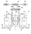
- FIGS. 3 and 5 The outline of the RF battery 10 of the embodiment and the cell stack 30 of the embodiment will be described with reference to FIGS. 3 to 5.
- the ions shown in the positive electrode tank 16 and the negative electrode tank 17 in FIGS. 3 and 5 are examples of ion species included in the electrolyte solution of each electrode.
- a solid line arrow means charging, and a broken line arrow means discharging.
- the RF battery 10 of the embodiment includes a single cell battery (FIG. 3) provided with the flow path 20 (FIG. 4) including the specific inclined groove described in the first and second embodiments as the bipolar plate 2. It is a multi-cell battery (FIGS. 4 and 5).
- the cell stack 30 of the embodiment includes the bipolar plate 2 provided with the flow path 20 (FIG. 4) including the specific inclined groove described in the first and second embodiments, and is used for a multi-cell battery. A specific configuration will be described below.
- the RF battery 10 includes a battery cell 10 ⁇ / b> C and a circulation mechanism that circulates and supplies an electrolytic solution to the battery cell 10 ⁇ / b> C.
- the RF battery 10 is connected to a power generation unit 420 and a load 440 such as a power system or a consumer via an AC / DC converter 400, a substation facility 410, and the like, and supplies power to the power generation unit 420. Charging is performed as a source, and discharging is performed using the load 440 as a power supply target.
- the power generation unit 420 include a solar power generator, a wind power generator, and other general power plants.
- the battery cell 10C is interposed between the positive electrode 14 to which the positive electrode electrolyte is supplied, the negative electrode 15 to which the negative electrode electrolyte is supplied, and the positive electrode 14 and the negative electrode 15 as shown in FIG. And a pair of bipolar plates 2 and 2 that further sandwich a positive electrode 14 and a negative electrode 15 that sandwich the diaphragm 11.
- the positive electrode 14 and the negative electrode 15 are reaction fields where an electrolyte containing an active material is supplied and the active material (ions) undergoes a battery reaction, and a porous material such as a fiber aggregate of carbon materials is used.
- the diaphragm 11 is a member that separates the positive electrode 14 and the negative electrode 15 and transmits predetermined ions, and an ion exchange membrane or the like is used.
- the battery cell 10C is typically configured using the cell frame 12 shown in FIG.
- the cell frame 12 includes a bipolar plate 2 and a frame body 120 formed on the outer periphery of the bipolar plate 2.
- a single cell battery having only one battery cell 10 ⁇ / b> C includes a set of cell frames 12 and 12.
- a multi-cell battery including a plurality of battery cells 10 ⁇ / b> C includes a plurality of sets of cell frames 12.
- one surface is a surface on which the positive electrode 14 is opposed and the other surface is a surface on which the negative electrode 15 is opposed.
- one surface is a positive electrode flow path and the other surface is a negative electrode electrolysis.
- FIG. 4 illustrates the bipolar plate 2 having a rectangular planar shape (outer shape), the planar shape of the bipolar plate 2 can be selected as appropriate.
- 4 illustrates the bipolar plate 2A of the first embodiment having the meshing grooves 210 and 220 that are inclined grooves and not including the distribution groove 214 and the aggregation groove 224 as the flow path 20.
- the frame body 120 is a member that supports the bipolar plate 2 and is used for supplying an electrolytic solution to the electrode disposed on the bipolar plate 2 and discharging the electrolytic solution from the electrode.
- FIG. 4 illustrates a rectangular frame having a rectangular window portion (penetrating portion) at the center.
- the frame 120 is made of a resin having excellent resistance to an electrolytic solution and excellent electrical insulation.
- the frame 120 is provided with an electrolyte supply path and a discharge path.
- the supply path includes a liquid supply hole (124i for the positive electrode and 125i for the negative electrode), a slit extending from the liquid supply hole to the window, and the like.
- the discharge path includes a drain hole (124o for the positive electrode and 125o for the negative electrode), a slit that extends from the window portion to the drain hole, and the like.
- the supply edge 200 (FIGS. 1 and 2) of the bipolar plate 2 is disposed so as to contact the inner peripheral edge connected to the supply path in the frame 120, and the discharge edge 202 is the inner peripheral edge connected to the discharge path in the frame 120. It arrange
- a rectifying groove (not shown) can be provided in the inner peripheral region between the above-described slit and the peripheral edge of the window portion and along the inner peripheral edge of the frame body 120.
- the supply-side rectifying groove can be provided along the lower end edge of the window portion
- the discharge-side rectifying groove can be provided along the upper end edge of the window portion.
- a rectifying groove (not shown) may be provided in the bipolar plate 2 along the periphery of the bipolar plate 2.
- the cell stack 30 is a laminate in which a cell frame 12 (bipolar plate 2), a positive electrode 14, a diaphragm 11, and a negative electrode 15 are stacked in order.
- a pair of end plates 32, 32 sandwiching the laminate, a connecting member 34 such as a long bolt connecting the end plates 32, 32, and a fastening member such as a nut are provided.
- the end plates 32 and 32 are tightened by the fastening member, the stacked body is maintained in the stacked state by the tightening force in the stacking direction.
- the cell stack 30 may be used in a form in which a predetermined number of battery cells 10C are used as sub cell stacks 30S and a plurality of sub cell stacks 30S are stacked.
- a seal member is disposed between the adjacent frame bodies 120 and 120 to hold the laminate in a liquid-tight manner.
- the circulation mechanism includes a positive electrode tank 16 that stores a positive electrode electrolyte that circulates and supplies the positive electrode 14, and a negative electrode tank 17 that stores a negative electrode electrolyte that circulates and supplies the negative electrode 15.
- pipes 162 and 164 connecting the positive electrode tank 16 and the battery cell 10C (cell stack 30), pipes 172 and 174 connecting the negative electrode tank 17 and the battery cell 10C (cell stack 30), and the battery cell 10C.
- Pumps 160 and 170 provided in the supply-side piping 162 and 172.
- the pipes 162, 164, 172, and 174 are respectively connected to the electrolyte distribution channels formed by the liquid supply holes 124i and 125i and the drain holes 124o and 125o of the plurality of stacked cell frames 12, Establish a circulation path for the electrolyte of the pole.
- At least one of the bipolar plates 2 and 2 constituting the battery cell 10C has a flow path 20 including the above-described inclined groove on the surface facing the electrode. It shall be provided.
- the pair of bipolar plates 2 and 2 only one of the bipolar plates 2 may be provided with a flow path 20 including an inclined groove, but both bipolar plates 2 and 2 include a flow path including an inclined groove. 20 is preferable because the utilization factor of the electrodes 14 and 15 of both electrodes can be increased.
- the bipolar plate 2 provided with the flow paths 20 on both the front and back sides can also be used.
- the multi-cell battery of the embodiment includes a plurality of bipolar plates 2 having flow paths on the front and back surfaces.
- a bipolar plate 2 examples include a form ( ⁇ 1) provided with inclined grooves only on one surface and a form ( ⁇ 2) provided with inclined grooves on both surfaces.
- the forms ( ⁇ 1) and ( ⁇ 2-1) can reduce a region where grooves overlap when the front and back surfaces of the bipolar plate 2 are seen through. Although depending on the inclination angle ⁇ , the groove width W, the distance C (FIGS. 1 and 2), etc., the overlapping region can be made only at the intersection of the grooves. Therefore, the positive electrode electrolyte flowing along the inclined groove on one surface of the bipolar plate 2 and the negative electrode electrolyte flowing along the inclined groove on the other surface can flow at different positions except for the above-mentioned intersections. Excellent flowability of electrolyte solution at each electrode.
- the reaction region of the positive electrode 14 and the reaction region of the negative electrode 15 sandwiching the bipolar plate 2 can be shifted. From this point, battery reactions tend to be easily performed, and it is expected that the utilization rate of the electrolytic solution can be increased. Furthermore, the bipolar plate 2 is easy to have high strength even when the thickness is thin and the groove depth is deep to some extent, and the number of inclined grooves can be increased. Therefore, this bipolar plate 2 is expected to easily flow the electrolytic solution uniformly over a wider range and easily increase the utilization factor of the electrodes.
- at least one of the channels provided on the surface includes an inclined groove, and the inclined groove included in one channel and the groove forming the other channel intersect with each other. This form can reduce the area
- the overlapping region can be made only at the intersection of the grooves.
- one electrolytic solution flowing along the inclined groove of one bipolar plate 2 and the other electrolytic solution flowing along the groove forming the flow path of the other bipolar plate 2 are excluded except for the above-mentioned intersection. It can flow at different positions facing each other, and is excellent in the flowability of the electrolyte solution at each electrode. From this point, further reduction of losses such as pump loss can be expected. Moreover, this form can shift the reaction region of the positive electrode 14 and the reaction region of the negative electrode 15. From this point, battery reactions tend to be easily performed, and it is expected that the utilization rate of the electrolytic solution can be increased.
- one bipolar plate 2 may include an inclined groove
- the other bipolar plate 2 may include the vertical groove or the lateral groove described above.
- both bipolar plates 2 include an inclined groove, and one bipolar plate 2 If the inclined groove of the other bipolar plate 2 and the inclined groove of the other bipolar plate 2 are arranged so as to intersect with each other, in addition to the improvement in the flowability of the electrolytic solution and the utilization rate of the electrolytic solution, the utilization rate of the electrode is further increased. It is preferable.
- the shape of the grooves forming the flow paths of each bipolar plate 2, the inclination direction and the inclination angle of the inclined grooves, etc. so that the grooves forming the flow paths intersect when arranged opposite to each other It is good to select.
- the grooves that form the flow paths on each surface are arranged in an intersecting state ( ⁇ 1), when the pair of ( ⁇ 2-1) bipolar plates 2 are disposed facing each other, the grooves on the opposing surfaces intersect It is advisable to adjust the arrangement direction of the bipolar plate 2 and so on.
- the inclined direction and the inclined groove provided on the surface facing the positive electrode 14 in one bipolar plate 2 disposed opposite to each other and the inclined groove provided on the surface facing the negative electrode in the other bipolar plate 2 may be the same, and they may be arranged so as not to substantially intersect.
- the inclined grooves are formed so that at least a part of the inclined grooves of the opposite bipolar plate 2 and the inclined groove of the other bipolar plate 2 do not overlap, the overlapping region is reduced. And the flowability of the electrolyte can be improved.
- the number of inclined grooves tends to decrease, and the utilization factor of the electrodes tends to decrease. Therefore, a configuration in which the above-described facing grooves are arranged in an intersecting state is preferable.
- the RF battery 10 of the embodiment includes the bipolar plate 2 (2A, 2B, etc.) of the embodiment, the electrode utilization rate is high. As a result, the RF battery 10 has low internal resistance and high battery efficiency. This effect will be specifically described in Test Example 1. Moreover, since the RF battery 10 includes the bipolar plate 2 provided with the flow path 20, it is excellent in the flowability of the electrolyte and can reduce losses such as pump loss. Since the cell stack 30 of the embodiment includes the bipolar plate 2 (2A, 2B, etc.) of the embodiment, the utilization rate of the electrodes can be increased, the RF battery having a low internal resistance and high battery efficiency, and the pump loss. Thus, it is possible to construct an RF battery that can reduce loss.
- RF batteries were constructed by preparing bipolar plates provided with inclined grooves having various inclination angles ⁇ , and the internal resistance of the RF battery and the current efficiency of the RF battery were determined.
- the prepared bipolar plate has a shape substantially similar to the bipolar plate 2B shown in FIG.
- Bipolar plate of planar shape rectangular long side length: 18cm (corresponding to the length L 2 of Gawahen'en here)
- Short side length 15 cm (corresponding to the length W 2 of the supply edge and the discharge edge here)
- Thickness 3mm
- Inclination angle ⁇ of inclined grooves 1 °, 3 °, 10 °, 20 °, 23 °, 30, 40 °
- Groove width W of inclined groove 1mm
- Groove depth of inclined groove 1mm Distance C between inclined grooves: 2 mm Engagement region: Yes, Single groove: No Distribution groove and aggregation groove: Yes, groove width W 214 , W 224 : 5 mm, groove depth: 1 mm
- a single cell battery and a multi-cell battery were prepared.
- the bipolar plates were arranged so that the inclined grooves provided on the bipolar plates arranged facing each other intersect each other.
- a rectangular bipolar plate (18 cm ⁇ 15 cm) having the same size and having a longitudinal groove, that is, a tilt angle of 0 ° is prepared, and an RF battery (sample No. 100) is prepared. It was constructed.
- This bipolar plate does not have an inclined groove, a distribution groove, and an aggregation groove, opens to the supply edge, opens to the discharge edge, and extends from the discharge edge to the introduction-side vertical groove extending in the orthogonal direction from the supply edge.
- a discharge-side vertical groove is provided that extends in the orthogonal direction and is independent of the introduction-side vertical groove.
- a meshing region is provided in which vertical grooves on the introduction side and vertical grooves on the discharge side are alternately arranged.
- the width of the longitudinal groove is 1 mm
- the depth of the longitudinal groove is 1 mm
- the distance between the grooves is 2 mm
- the length in the long side direction in the meshing region is 17 cm
- the length of the region other than the meshing region provided on the introduction side and the discharge side, respectively Is 5 mm.
- the prepared RF battery was subjected to a constant current (54 A here) charge / discharge test.
- a vanadium-based electrolyte was used, and the temperature was 35 ° C. and the flow rate of the electrolyte at each electrode was 0.7 L / min.
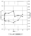
- the charge voltage and discharge voltage were measured for two cycles except the first cycle, and the cell resistance ( ⁇ ⁇ cm 2 / cell) was determined using the average charge voltage and average discharge voltage of the two cycles. . The results are shown in FIG.
- Sample No. 1 to No. Reference numeral 7 denotes an RF battery including a bipolar plate provided with inclined grooves that intersect non-orthogonally with the long and short sides of the rectangular bipolar plate.
- Sample No. Reference numeral 100 denotes an RF battery including a bipolar plate provided with vertical grooves parallel to the long sides of the rectangular bipolar plate and perpendicular to the short sides, which is similar to a conventional vertical groove configuration.
- sample no. 1 to No. The RF battery of No. 7 has a sample No. with vertical grooves. It can be seen that the cell resistance tends to be small compared to 100 RF batteries. In this test, it can be seen that if the inclination angle ⁇ of the inclined groove is 1 ° or more, the cell resistance is effectively reduced. When the inclination angle ⁇ is larger, it can be said that the cell resistance is likely to be lowered particularly when it is 3 ° or more, further 10 ° or more and more than 10 °. Further, it can be said that the cell resistance is easily lowered when the inclination angle ⁇ is 40 ° or less, particularly less than 40 ° or 35 ° or less.
- the RF battery of No. 7 has a sample No. with vertical grooves. It can be seen that the battery efficiency is high compared to 100 RF batteries. In this test, if it is 1 degree or more, it can be said that it is effective in improving battery efficiency. When the inclination angle ⁇ is larger, it can be said that the battery efficiency is more likely to be improved particularly when it is 3 ° or more, further 10 ° or more and more than 10 °. If the inclination angle ⁇ is 40 ° or less, it can be said that it is easy to have high battery efficiency. Therefore, in consideration of cell resistance and battery efficiency, it can be said that the inclination angle ⁇ of the inclined groove is preferably 1 ° or more and less than 40 °.
- the planar shape of the bipolar plate 2 is changed.
- a shape including a curve in at least a part of the periphery of the bipolar plate 2 such as an ellipse or a racetrack, or a polygonal shape such as a hexagon or an octagon.
- the introduction port and the discharge port provided at one end of the inclined groove are a portion (supply edge) where the electrolyte solution is introduced at the peripheral edge of the bipolar plate 2 or a portion that discharges the electrolyte solution facing this introduction portion (
- the inclined grooves provided away from the discharge edge are likely to increase. Therefore, it is possible to provide the distribution groove 214 and the aggregation groove 224 that open to the peripheral edge at appropriate positions on the peripheral edge of the bipolar plate 2.
- the groove width W is partially different, and there are a thick portion and a thin portion locally, a meandering shape such as a wavy line shape and a zigzag shape.
- the peripheral edge of the groove in plan view is extracted, and a quadrangle including the peripheral edge is taken.
- the quadrangle is a parallelogram, and the opposite two sides non-orthogonally intersect the long side and the short side of the assumed rectangle described above are defined as inclined grooves.
- Other examples include a tapered shape in which the groove width W becomes narrower from one end portion (introduction port 215 or discharge port 225) of the inclined groove toward the other end portion.
- (3) Change the cross-sectional shape of the inclined groove examples include a semicircular arc shape, a V shape, a U shape, and a dovetail shape in which the opening width of the groove is narrower than the width of the bottom surface.
- inclined grooves having different planar shapes and cross-sectional shapes, inclined grooves having different sizes (inclination angle ⁇ , groove width W, groove depth, etc.), and the groove depth is partially Including different inclined grooves.
- it includes inclined grooves whose distances C are partially different.
- a vertical groove parallel to the side edge 204 is included.
- It can be set as the form which does not have the meshing area
- the inclined groove is not a continuous groove but a plurality of intermittent groove groups.
- the engagement grooves 210 and 220 are a group of a plurality of groove pieces provided at intervals in the inclination direction. In this case, when the electrode on the bipolar plate 2 receives the electrolytic solution in the groove facing region corresponding to each groove piece, the periphery surrounding the groove facing region can be used as the reaction region. Therefore, it is expected that the reaction area can be increased and the battery reactivity is excellent.
- a virtual extension line is taken along the inclination angle ⁇ of the groove piece opened to the supply edge 200 or the distribution groove 214 or the groove piece arranged in the vicinity of the supply edge 200 or the distribution groove 214,
- the groove group arranged on the extension line can be regarded as a groove group forming one inclined groove on the introduction side. Further, of the groove group, take a virtual extension line along the inclination angle ⁇ of the groove piece that opens to the discharge edge 202 or the aggregation groove 224, or the groove piece that is disposed in the vicinity of the discharge edge 202 or the aggregation groove 224,
- the groove group arranged on the extension line can be regarded as a groove group forming one discharge side inclined groove.
Landscapes
- Life Sciences & Earth Sciences (AREA)
- Engineering & Computer Science (AREA)
- Manufacturing & Machinery (AREA)
- Sustainable Development (AREA)
- Sustainable Energy (AREA)
- Chemical & Material Sciences (AREA)
- Chemical Kinetics & Catalysis (AREA)
- Electrochemistry (AREA)
- General Chemical & Material Sciences (AREA)
- Fuel Cell (AREA)
Abstract
Description
本出願は、2016年12月07日付の日本国出願「特願2016-238041」に基づく優先権を主張し、上記日本国出願に記載された全ての記載内容を援用するものである。
電解液が流通される電極に対向配置される双極板であって、
前記双極板の表裏面の少なくとも一面に前記電解液を流通する流路を備え、
前記双極板の表裏面の少なくとも一面に設けられた流路は、
電解液を導入する導入路と、前記導入路とは連通せずに独立しており、前記電解液を排出する排出路とを備え、
前記導入路及び前記排出路の少なくとも一方は、前記双極板の外縁を内包する長方形を想定した場合にこの長方形における長辺及び短辺に対して非直交に交差する傾斜溝を含む。
電解液が流通される電極に対向配置される双極板であって、
前記双極板の表裏面のそれぞれに前記電解液を流通する流路を備え、
前記双極板の表裏面の少なくとも一面に設けられた流路は、
電解液を導入する導入路と、前記導入路とは連通せずに独立しており、前記電解液を排出する排出路とを備え、
前記導入路及び前記排出路の少なくとも一方は、前記双極板の外縁を内包する長方形を想定した場合にこの長方形における長辺及び短辺に対して非直交に交差する傾斜溝を含み、
前記双極板の表裏面を平面透視した場合に前記双極板の一面に設けられた前記傾斜溝と、他面に設けられて流路をなす溝とが交差するように配置される溝の組を含む。
上記の本開示に係る双極板を備える。
上記の本開示に係るセルスタックを備える。
電極の利用率をより高められるレドックスフロー電池が望まれている。
上記の本開示の双極板は、電極の利用率を高められる。上記の本開示のセルスタック、上記の本開示のレドックスフロー電池は、電極の利用率が高い。
最初に本願発明の実施態様を列記して説明する。
(1)本開示の一態様に係る双極板は、
電解液が流通される電極に対向配置される双極板であって、
前記双極板の表裏面の少なくとも一面に前記電解液を流通する流路を備え、
前記双極板の表裏面の少なくとも一面に設けられた流路は、
電解液を導入する導入路と、前記導入路とは連通せずに独立しており、前記電解液を排出する排出路とを備え、
前記導入路及び前記排出路の少なくとも一方は、前記双極板の外縁を内包する長方形を想定した場合にこの長方形における長辺及び短辺に対して非直交に交差する傾斜溝を含む。
(α)溝部の一端が、双極板の周縁において電解液の供給側に配置される部分(供給縁)に開口する。
(β)溝部の一端が、後述する分配溝に連続する。
(γ)供給縁に開口せず、かつ分配溝に連続しない溝部であって、この溝部の一端から供給縁までの距離、又は分配溝までの距離がこの溝部の他端から後述する排出縁までの距離、又は後述する集約溝までの距離よりも短い。
ここでの「排出路」とは、流路を構成する溝部のうち、以下の(χ)から(ω)のいずれかの条件を満たすものをいう。
(χ)溝部の一端が、双極板の周縁において電解液の排出側に配置される部分(排出縁)に開口する。
(ψ)溝部の一端が、後述する集約溝に連続する。
(ω)排出縁に開口せず、かつ集約溝に連続しない溝部であって、この溝部の一端から排出縁までの距離、又は集約溝までの距離が上記溝部の他端から上記の供給縁までの距離、又は上記の分配溝までの距離よりも短い。
「双極板の外縁を内包する長方形」は、双極板の平面形状(外形)が長方形(正方形を含む)であれば、外形と同じ長方形であり、非長方形状であれば、外縁を内包する最小の長方形である。
これらの事項は、後述する(2)の双極板についても同様に適用できる。
電解液が流通される電極に対向配置される双極板であって、
前記双極板の表裏面のそれぞれに前記電解液を流通する流路を備え、
前記双極板の表裏面の少なくとも一面に設けられた流路は、
電解液を導入する導入路と、前記導入路とは連通せずに独立しており、前記電解液を排出する排出路とを備え、
前記導入路及び前記排出路の少なくとも一方は、前記双極板の外縁を内包する長方形を想定した場合にこの長方形における長辺及び短辺に対して非直交に交差する傾斜溝を含み、
前記双極板の表裏面を平面透視した場合に前記双極板の一面に設けられた前記傾斜溝と、他面に設けられて流路をなす溝とが交差するように配置される溝の組を含む。
前記少なくとも一面に設けられた流路は、
前記導入路に含む前記傾斜溝と前記排出路に含む前記傾斜溝とが隣り合って並ぶ傾斜溝の組を少なくとも一つ含む形態が挙げられる。
前記少なくとも一面に設けられた流路は、
前記導入路及び前記排出路の双方が複数の前記傾斜溝を含み、
前記導入路に含む前記傾斜溝と前記排出路に含む前記傾斜溝とが互いに噛み合うように配置される噛合領域を有する形態が挙げられる。
前記傾斜溝の一端は、前記双極板の周縁に開口する形態が挙げられる。
前記導入路は、
前記双極板の周縁に沿って開口し、前記導入路に含む複数の前記傾斜溝の一端に連続して、各傾斜溝に前記電解液を供給する分配溝を含み、
前記排出路は、
前記双極板の周縁における前記分配溝側とは対向する側に開口し、前記排出路に含む複数の前記傾斜溝の一端に連続して、これらの傾斜溝からの前記電解液をまとめて排出する集約溝を含む形態が挙げられる。
前記傾斜溝の一端部からみて他端部は、この傾斜溝の溝幅以上にずれて配置される形態が挙げられる。
前記傾斜溝の傾斜角が1°以上である形態が挙げられる。
「傾斜溝の傾斜角」とは、双極板がRF電池に組み付けられた場合に上述の想定上の長方形において電解液の流通方向に沿って配置される辺に対する角度とする。
前記傾斜溝の傾斜角が40°以下である形態が挙げられる。
上記(1)から(9)のいずれか一つに記載の双極板を備える。
前記表裏面の少なくとも一面に前記傾斜溝が設けられた一組の双極板を含む電池セルを備え、
前記一組の双極板は、一方の前記双極板における正極電極との対向面に設けられた前記傾斜溝と、他方の前記双極板における負極電極との対向面に設けられた前記傾斜溝とが互いに交差するように配置される形態が挙げられる。
(10)又は(11)のセルスタックを備える。
以下、図面を参照して、本願発明の実施形態を具体的に説明する。図中、同一符号は同一名称物を示す。
図1を参照して実施形態1の双極板2Aを説明する。
(概要)
実施形態1の双極板2Aは、RF電池の構成要素に利用され、電流を流すが電解液を通さない導電性の平板材である。双極板2Aは、電解液が流通される電極(正極電極14又は負極電極15、後述の図4)に対向配置される表裏面の少なくとも一面に電解液を流通する流路を備える。双極板2Aの表裏面の少なくとも一面に設けられた流路20は、電解液を導入する導入路21と、導入路21とは連通せずに独立しており、電解液を排出する排出路22とを備える。特に、実施形態1の双極板2Aでは、導入路21及び排出路22の少なくとも一方は、双極板2Aの外縁を内包する長方形を想定した場合にこの長方形における長辺及び短辺に対して非直交に交差する傾斜溝(ここでは噛合溝210,220など)を含む。この例の双極板2Aの平面形状は長方形である。そのため、「外縁を内包する長方形の長辺及び短辺」とは、双極板2Aの周縁を構成する長辺及び短辺に相当する。以下の説明では、双極板2Aの周縁をつくる四辺のうち、後述するセルフレーム12の枠体120に設けられる供給路近くに配置される一辺を供給縁200、枠体120に設けられる排出路近くに配置される他辺を排出縁202と呼ぶことがある。図1及び後述する図2では、下端縁を供給縁200、上端縁を排出縁202とする。また、図1及び図2では、双極板2A,2Bが縦長の長方形であり、上下に配置される短辺を供給縁200,排出縁202とするが、図4に示すように双極板2が横長の長方形であり、上下に配置される長辺を供給縁200,排出縁202とすることもできる。
(α)流路20は、導入路21及び排出路22の双方が複数の傾斜溝を含み、各傾斜溝の一端が双極板2Aの周縁(供給縁200,排出縁202)に開口する。即ち、導入路21に含む傾斜溝(後述の噛合溝210,単独溝212)は、双極板2Aの供給縁200に開口する導入口215を含む。排出路22に含む傾斜溝(後述の噛合溝220,単独溝222)は、双極板2Aの供給縁200とは対向する側(図1では上側)に位置する排出縁202に開口する排出口225を含む。
(β)双極板2Aは、導入路21に含む傾斜溝(噛合溝210)と排出路22に含む傾斜溝(噛合溝220)とが互いに噛み合うように配置される噛合領域24(図1では二点鎖線で囲まれる仮想の領域)を有する。即ち、双極板2Aは、導入路21に含む傾斜溝(噛合溝210)と排出路22に含む傾斜溝(噛合溝220)とが隣り合って並ぶ傾斜溝の組を複数有する。
(γ)傾斜溝(210,212,220,222)の傾斜角θが1°以上40°以下である。この例の双極板2A及び後述する実施形態2の双極板2Bはいずれも、RF電池に組み付けられた場合に、上述した想定上の長方形における側辺縁204を電解液の流通方向に沿って配置される辺とする。図1及び図2では長辺を側辺縁204とし、図4では短辺を側辺縁204とする。図1及び図2では、傾斜角θが分かり易いように、側辺縁204に平行な直線を一点鎖線で示し、この直線に対する角度として示す。
(δ)噛合溝210,220に加えて、噛合領域24外の領域(図1では、左下の角部及び右上の角部)にも傾斜溝(単独溝212,222)を含む。単独溝212,222は、互いに噛み合うように配置されていない。
傾斜溝のうち、導入側の噛合溝210の一端は、供給縁200に開口し、他端は、排出縁202から直交方向に長さLeの地点に位置して閉じている。排出側の噛合溝220の一端は、排出縁202に開口し、他端は、供給縁200から直交方向に長さLeの地点に位置して閉じている。両噛合溝210,220の他端が閉じていることで、導入側の噛合溝210と、排出側の噛合溝220とは独立した流路を形成する。導入側の噛合溝210における供給縁200から、図1に示す下側の長さLeの地点までの範囲を除く領域と、排出側の噛合溝220における排出縁202から、図1に示す上側の長さLeの地点までの範囲を除く領域とが噛合領域24を構成する。双極板2A上に配置される電極において、噛合領域24に対応する領域のうち、噛合溝210,220に対応する溝対向領域の両側を反応領域とすることができる。電極の反応領域は噛合溝210,220に挟まれるように設けられるといえる。また、電極における導入側の噛合溝210に対向する溝対向領域を未反応の電解液の受取領域とし、排出側の噛合溝220に対向する溝対向領域を反応済の電解液の排出領域とすることができる。そのため、電極の反応領域は、未反応の電解液の受取領域と反応済の電解液の排出領域とに挟まれるといえる。
双極板2Aの平面形状、傾斜角θなどによっては、噛合溝210,220(噛合領域24)を十分に確保できず、双極板2Aの広い範囲を電解液の流通領域に利用できないことが考えられる。そこで、導入側の傾斜溝として、排出側の傾斜溝に隣り合わず、かつ上述の供給縁200から所定の地点(ここでは排出縁202に近い上側の長さLeの地点)までに至らない単独溝212を備えることができる。排出側の傾斜溝として、導入側の傾斜溝に隣り合わず、かつ上述の排出縁202から所定の地点(ここでは供給縁200に近い下側の長さLeの地点)までに至らない単独溝222を備えることができる。単独溝212,222を備えると、噛合溝210,220を設けられないような比較的狭い領域、図1では左下の角部近傍や右上の角部近傍を、電解液の流通領域にすることができる。双極板2A上の電極は、単独溝212に対応した溝対向領域から電解液を受け取り、この溝対向領域の近傍を反応領域として電池反応を行う。反応済の電解液は電極内を介して双極板2Aの排出路22に排出される。
傾斜溝の平面形状は、図1に示す平行四辺形状が代表的である。この傾斜溝は、その長手方向の全域に亘って、溝幅W(ここでは供給縁200、排出縁202に沿った長さ)が等しい。この例の傾斜溝のように溝幅Wが傾斜溝の全長に亘って一様であると、電解液の流通圧力の変動が生じ難く、電解液の流通性に優れる。また、この例のように全ての傾斜溝の形状が等しいと、溝幅Wや隣り合う傾斜溝間の距離Cなどにもよるが、双極板2Aにおける傾斜溝の個数を多くし易く、双極板2Aの広い範囲に亘って電解液を均一的に流し易い。
傾斜溝における傾斜角θ、傾斜溝における溝幅W、溝深さ、溝長さ(ここでは傾斜方向に沿った長さ)、隣り合う傾斜溝間の距離C、噛合溝210,220における噛合領域24外に配置される導入口215側の領域、排出口225側の領域の大きさ(例えば、側辺縁204に沿った長さLe)などは適宜選択できる。この例では、全ての傾斜溝において、溝幅W及び溝深さが等しく、噛合溝210,220の溝長さが等しい。そのため、双極板2Aが単純な形状になり易く、製造性にも優れる。なお、図1,図2,図4は傾斜溝を模式的に示し、傾斜角θなどのパラメータは後述の範囲を満たさない場合がある。
双極板2Aは、表裏面の一面に傾斜溝を含む流路20を備え、他面が平面で形成されて流路を備えていない形態(α)、両面に電解液の流路を備え、一面に傾斜溝を含む流路20を備え、他面に傾斜溝を含まない流路を備える形態(β1)、両面に傾斜溝を含む流路20を備える形態(β2)とすることができる。形態(β1)において他面の流路は、例えば、上述の縦溝や横溝などを含むことが挙げられる。この双極板2Aは、その表裏面を平面透視した場合に一面に設けられた傾斜溝と、他面に設けられて流路をなす縦溝や横溝などの溝とが交差するように配置される。形態(β2)において、表裏面の傾斜溝の傾斜方向及び傾斜角の少なくとも一方が異なると、この双極板2Aの表裏面を平面透視した場合に一面に設けられた傾斜溝と、他面に設けられた傾斜溝とが交差するように配置される(以下、この形態をβ2-1と呼ぶことがある)。形態(β2-1)では、各面の傾斜溝において傾斜角が等しく、傾斜方向が異なる形態、各面の傾斜溝の傾斜方向が等しく、傾斜角が異なる形態、各面の傾斜溝の傾斜角及び傾斜方向の双方が異なる形態とすることができる。又は、形態(β2)において、傾斜角及び傾斜方向が同じであり、実質的に交差しない形態(β2-2)とすることもできる。形態(β2-2)では、平面透視した場合に双極板2Aの一面の傾斜溝と他面の傾斜溝とが完全に重複するように、表裏の流路20を同様な仕様とすることができる。又は、形態(β2-2)では、平面透視した場合に双極板2Aの一面の傾斜溝と他面の傾斜溝との少なくとも一部が重複しないように、傾斜溝の形成位置がずれていると、表裏面の溝が重複する領域を低減でき、双極板2Aの強度を高め易い。但し、この場合、傾斜溝の個数が少なくなり易く、電極の利用率の低下を招き易い。従って、表裏面の溝が交差状態で配置される形態(β1)、形態(β2-1)の方が好ましい。また、表裏面の少なくとも一面の流路20は、この例のように噛合領域24を備えることが好ましい。表裏面の流路に関する事項は、後述する実施形態2についても同様に適用できる。
実施形態の双極板2Aの構成材料は、電気抵抗が小さい導電性材料であって、電解液と反応せず、電解液に対する耐性(耐薬品性、耐酸性など)を有するものが好適に利用できる。更に、適度な剛性を有する構成材料であると、流路20を構成する溝の形状や寸法が長期に亘って変化し難く、流路20の具備による効果(電極の利用率の向上、流通抵抗の低減、ポンプロスなどの損失の低減など)を維持し易く好ましい。
実施形態1の双極板2Aは、特定の傾斜溝(210,220,212,222)を備えるため、その角部近傍などを電解液の流通領域とすることができ、流通領域を増大できる。従って、実施形態1の双極板2Aは、RF電池に組み付けられることで、電極の利用率を高められる。この例の双極板2Aは、導入路21及び排出路22の双方に傾斜溝を備えることからも、流通領域を増大し易く、電極の利用率を高め易い。また、この例の双極板2Aでは、より多くの傾斜溝(単独溝212,222を含む)を備えることからも、電極の利用率を高め易い。
図2を参照して実施形態2の双極板2Bを説明する。
実施形態2の双極板2Bの基本的構成は、実施形態1の双極板2Aと同様であり、電極との対向面に、導入路21及び排出路22を含む流路20を備え、導入路21及び排出路22の少なくとも一方が傾斜溝(210,212,220,222)を含む。実施形態2の双極板2Bにおける実施形態1との主な相違点は、導入路21が、供給縁200を含む双極板2Bの周縁に沿って設けられ、この周縁に開口する分配溝214を含み、排出路22が、排出縁202を含む双極板2Bの周縁に沿って設けられ、この周縁に開口する集約溝224を含むこと、傾斜角θが比較的大きいことが挙げられる。以下、実施形態1との相違点を詳細に説明し、実施形態1と重複する構成(形状、大きさなど)及び効果は詳細な説明を省略する。
実施形態2の双極板2Bは、特定の傾斜溝(210,220,212,222)を備えるため、実施形態1と同様に、RF電池に組み付けられた際に電極の利用率を高められる。また、実施形態2の双極板2Bは、独立した導入路21及び排出路22を備えるため、実施形態1と同様に、RF電池に組み付けられた際に、電解液を電池反応に効率よく利用できる。
図3から図5を参照して、実施形態のRF電池10、実施形態のセルスタック30の概要を説明する。
図3,図5の正極タンク16内及び負極タンク17内に示すイオンは、各極の電解液中に含むイオン種の一例を示す。図3において実線矢印は充電、破線矢印は放電を意味する。
RF電池10は、図3に示すように、電池セル10Cと、電池セル10Cに電解液を循環供給する循環機構とを備える。代表的には、RF電池10は、交流/直流変換器400や変電設備410などを介して、発電部420と、電力系統や需要家などの負荷440とに接続され、発電部420を電力供給源として充電を行い、負荷440を電力提供対象として放電を行う。発電部420は、例えば、太陽光発電機、風力発電機、その他一般の発電所などが挙げられる。
・電池セル
電池セル10Cは、図4に示すように、正極電解液が供給される正極電極14と、負極電解液が供給される負極電極15と、正極電極14,負極電極15間に介在される隔膜11と、隔膜11を挟む正極電極14及び負極電極15を更に挟む一組の双極板2,2を備える。
隔膜11は、正極電極14,負極電極15間を分離すると共に所定のイオンを透過する部材であり、イオン交換膜などが利用される。
電池セル10Cは、代表的には、図4に示すセルフレーム12を用いて構成される。セルフレーム12は、双極板2と、双極板2の外周に形成される枠体120とを備える。電池セル10Cを一つのみ備える単セル電池では、一組のセルフレーム12,12を備える。電池セル10Cを複数備える多セル電池では、複数組のセルフレーム12を備える。多セル電池では、一面を正極電極14が対向配置される面、他面を負極電極15が対向配置される面とし、代表的には、一面に正極電解液の流路、他面に負極電解液の流路を備える双極板2を複数備える形態が挙げられる。図4では平面形状(外形)が長方形である双極板2を例示するが、双極板2の平面形状は適宜選択できる。また、図4では流路20として、傾斜溝である噛合溝210,220を有し、分配溝214及び集約溝224を有さない実施形態1の双極板2Aを例示する。
セルスタック30は、図4,図5に示すように、セルフレーム12(双極板2)と、正極電極14と、隔膜11と、負極電極15とが順に複数積層された積層体と、積層体を挟む一対のエンドプレート32,32と、エンドプレート32,32間を繋ぐ長ボルトなどの連結材34及びナットなどの締結部材とを備える。締結部材によってエンドプレート32,32間が締め付けられると、積層体は、その積層方向の締付力によって積層状態が保持される。
セルスタック30は、所定数の電池セル10Cをサブセルスタック30Sとし、複数のサブセルスタック30Sを積層した形態で利用されることがある。
サブセルスタック30Sやセルスタック30における電池セル10Cの積層方向の両端に位置するセルフレームには双極板2を含む集電板が配置されたものが利用される。
隣り合う枠体120,120間にはシール部材が配置され、積層体を液密に保持する。
循環機構は、図3,図5に示すように正極電極14に循環供給する正極電解液を貯留する正極タンク16と、負極電極15に循環供給する負極電解液を貯留する負極タンク17と、正極タンク16と電池セル10C(セルスタック30)間を接続する配管162,164と、負極タンク17と電池セル10C(セルスタック30)間を接続する配管172,174と、電池セル10Cへの供給側の配管162,172に設けられたポンプ160,170とを備える。配管162,164,172,174はそれぞれ、積層された複数のセルフレーム12の給液孔124i,125i及び排液孔124o,125oによって形成される電解液の流通管路などに接続されて、各極の電解液の循環経路を構築する。
実施形態の単セル電池では、電池セル10Cを構成する一組の双極板2,2のうち、少なくとも一方の双極板2は、その電極との対向面に上述の傾斜溝を含む流路20が設けられたものとする。一組の双極板2,2のうち、一方の双極板2にのみ傾斜溝を含む流路20が設けられた形態とすることができるが、両双極板2,2に傾斜溝を含む流路20が設けられていると、両極の電極14,15の利用率を高められて好ましい。表裏の両面に流路20が設けられた双極板2を利用することもできる。
実施形態のRF電池10は、実施形態の双極板2(2A,2Bなど)を備えるため、電極の利用率が高い。その結果、RF電池10は、内部抵抗が低く、電池効率が高い。この効果を試験例1で具体的に説明する。また、RF電池10は、流路20が設けられた双極板2を備えるため、電解液の流通性に優れ、ポンプロスなどの損失を低減できる。実施形態のセルスタック30は、実施形態の双極板2(2A,2Bなど)を備えるため、電極の利用率を高められて、内部抵抗が低かったり、電池効率が高かったりするRF電池、更にポンプロスなどの損失も低減できるRF電池を構築できる。
種々の傾斜角θである傾斜溝が設けられた双極板を用意してRF電池を構築し、RF電池の内部抵抗、RF電池の電流効率を求めた。
双極板の平面形状:長方形
長辺の長さ:18cm(ここでは側辺縁の長さL2に相当)
短辺の長さ:15cm(ここでは供給縁及び排出縁の長さW2に相当)
厚さ:3mm
傾斜溝の傾斜角θ:1°,3°,10°,20°,23°,30,40°
傾斜溝の溝幅W:1mm
傾斜溝の溝深さ:1mm
傾斜溝間の距離C:2mm
噛合領域:有り、単独溝:なし
分配溝及び集約溝:有り、溝幅W214,W224:5mm、溝深さ:1mm、
供給側部分の長さ及び排出側部分の長さ:短辺の長さと同じ(15cm)、
側方部分の長さL4:17cm(=L2-(Le+W214)=L2-(Le+W224))
噛合領域以外の領域の長さLe:5mm
電流効率(%)=(放電時間/充電時間)×100
電圧効率(%)=平均放電電圧(V)/平均充電電圧(V)×100
電池効率(%)=電流効率(%)×電圧効率(%)×0.01

実施形態の双極板2、実施形態のRF電池10、実施形態のセルスタック30について、以下の少なくとも一つの変更が可能である。
(1)双極板2の平面形状を変更する。例えば、楕円やレーストラック状など、双極板2の周縁の少なくとも一部に曲線を含む形状や、六角形や八角形などの多角形状などが挙げられる。
この場合、傾斜溝の一端部に設けられる導入口や排出口が、双極板2の周縁における電解液が導入される部分(供給縁)やこの導入部分に対向し、電解液を排出する部分(排出縁)から離れて設けられる傾斜溝が多くなり易い。従って、双極板2の周縁の適宜な位置に、この周縁に開口する分配溝214や集約溝224を備えることが挙げられる。
(2)傾斜溝の平面形状を変更する。例えば、溝幅Wが部分的に異なり、太い箇所や細い箇所を局所的に有するもの、波線状やジグザグ状などの蛇行形状などが挙げられる。この場合、平面視した溝の周縁を抽出し、この周縁を内包する四角形をとる。この四角形が平行四辺形であり、対向する二辺が上述した想定上の長方形の長辺及び短辺に非直交に交差するものを傾斜溝とする。
その他、傾斜溝の一端部(導入口215又は排出口225)から他端部に向かって、溝幅Wが細くなるテーパ形状などが挙げられる。
(3)傾斜溝の横断面形状を変更する。例えば、半円弧状、V字状、U字状、溝の開口幅が底面の幅よりも狭い蟻溝状などが挙げられる。
(5)傾斜溝に加えて、側辺縁204に平行な縦溝を含む。
(6)導入側の傾斜溝と排出側の傾斜溝とが交互に並ぶ噛合領域を有さない形態とすることができる。例えば、複数の導入側の傾斜溝群と、複数の排出側の傾斜溝群とが交互に並ぶ、又は複数の導入側の傾斜溝群と複数の排出側の傾斜溝群とが隣り合って並ぶ。
(7)傾斜溝を連続した溝ではなく、断続した複数の溝群とする。
例えば、噛合溝210,220をその傾斜方向に間隔をあけて設けられた複数の溝片の群とする。この場合、双極板2上の電極は各溝片に対応する溝対向領域で電解液を受け取ると、この溝対向領域を囲む周囲を反応領域に利用できる。従って、反応領域を増大でき、電池反応性に優れると期待される。なお、溝群のうち、供給縁200又は分配溝214に開口する溝片、又は供給縁200又は分配溝214の近傍に配置される溝片の傾斜角θに沿った仮想の延長線をとり、この延長線上に配置される溝群を一つの導入側の傾斜溝を形成する溝群と見做すことができる。また、溝群のうち、排出縁202又は集約溝224に開口する溝片、又は排出縁202又は集約溝224の近傍に配置される溝片の傾斜角θに沿った仮想の延長線をとり、この延長線上に配置される溝群を一つの排出側の傾斜溝を形成する溝群と見做すことができる。
20 流路
21 導入路
22 排出路
24 噛合領域
200 供給縁
202 排出縁
204 側辺縁
210,220 噛合溝(傾斜溝)
212,222 単独溝(傾斜溝)
214 分配溝
215 導入口
224 集約溝
225 排出口
10 レドックスフロー電池(RF電池)
10C 電池セル
11 隔膜
14 正極電極
15 負極電極
16 正極タンク
17 負極タンク
160,170 ポンプ
162,164,172,174 配管
12 セルフレーム
120 枠体
124i,125i 給液孔
124o,125o 排液孔
30 セルスタック
30S サブセルスタック
32 エンドプレート
34 連結材
400 交流/直流変換器
410 変電設備
420 発電部
440 負荷
Claims (12)
- 電解液が流通される電極に対向配置される双極板であって、
前記双極板の表裏面の少なくとも一面に前記電解液を流通する流路を備え、
前記双極板の表裏面の少なくとも一面に設けられた流路は、
電解液を導入する導入路と、前記導入路とは連通せずに独立しており、前記電解液を排出する排出路とを備え、
前記導入路及び前記排出路の少なくとも一方は、前記双極板の外縁を内包する長方形を想定した場合にこの長方形における長辺及び短辺に対して非直交に交差する傾斜溝を含む双極板。 - 電解液が流通される電極に対向配置される双極板であって、
前記双極板の表裏面のそれぞれに前記電解液を流通する流路を備え、
前記双極板の表裏面の少なくとも一面に設けられた流路は、
電解液を導入する導入路と、前記導入路とは連通せずに独立しており、前記電解液を排出する排出路とを備え、
前記導入路及び前記排出路の少なくとも一方は、前記双極板の外縁を内包する長方形を想定した場合にこの長方形における長辺及び短辺に対して非直交に交差する傾斜溝を含み、
前記双極板の表裏面を平面透視した場合に前記双極板の一面に設けられた前記傾斜溝と、他面に設けられて流路をなす溝とが交差するように配置される溝の組を含む双極板。 - 前記少なくとも一面に設けられた流路は、
前記導入路に含む前記傾斜溝と前記排出路に含む前記傾斜溝とが隣り合って並ぶ傾斜溝の組を少なくとも一つ含む請求項1又は請求項2に記載の双極板。 - 前記少なくとも一面に設けられた流路は、
前記導入路及び前記排出路の双方が複数の前記傾斜溝を含み、
前記導入路に含む前記傾斜溝と前記排出路に含む前記傾斜溝とが互いに噛み合うように配置される噛合領域を有する請求項3に記載の双極板。 - 前記傾斜溝の一端は、前記双極板の周縁に開口する請求項1から請求項4のいずれか1項に記載の双極板。
- 前記導入路は、
前記双極板の周縁に沿って開口し、前記導入路に含む複数の前記傾斜溝の一端に連続して、各傾斜溝に前記電解液を供給する分配溝を含み、
前記排出路は、
前記双極板の周縁における前記分配溝側とは対向する側に開口し、前記排出路に含む複数の前記傾斜溝の一端に連続して、これらの傾斜溝からの前記電解液をまとめて排出する集約溝を含む請求項1から請求項5のいずれか1項に記載の双極板。 - 前記傾斜溝の一端部からみて他端部は、この傾斜溝の溝幅以上にずれて配置される請求項1から請求項6のいずれか1項に記載の双極板。
- 前記傾斜溝の傾斜角が1°以上である請求項1から請求項7のいずれか1項に記載の双極板。
- 前記傾斜溝の傾斜角が40°以下である請求項1から請求項8のいずれか1項に記載の双極板。
- 請求項1から請求項9のいずれか1項に記載の双極板を備えるセルスタック。
- 前記表裏面の少なくとも一面に前記傾斜溝が設けられた一組の双極板を含む電池セルを備え、
前記一組の双極板は、一方の前記双極板における正極電極との対向面に設けられた前記傾斜溝と、他方の前記双極板における負極電極との対向面に設けられた前記傾斜溝とが互いに交差するように配置される請求項10に記載のセルスタック。 - 請求項10又は請求項11のセルスタックを備えるレドックスフロー電池。
Priority Applications (6)
| Application Number | Priority Date | Filing Date | Title |
|---|---|---|---|
| EP17878541.6A EP3553864B1 (en) | 2016-12-07 | 2017-06-21 | Bipolar plate, cell stack, and redox flow battery |
| US16/467,659 US11108057B2 (en) | 2016-12-07 | 2017-06-21 | Bipolar plate, cell stack, and redox flow battery |
| JP2018554810A JP6970389B2 (ja) | 2016-12-07 | 2017-06-21 | 双極板、セルスタック、及びレドックスフロー電池 |
| CN201780075042.3A CN110050372B (zh) | 2016-12-07 | 2017-06-21 | 双极板、单元堆和氧化还原液流电池 |
| AU2017373097A AU2017373097A1 (en) | 2016-12-07 | 2017-06-21 | Bipolar plate, cell stack, and redox flow battery |
| KR1020197016207A KR20190089171A (ko) | 2016-12-07 | 2017-06-21 | 쌍극판, 셀 스택 및 레독스 플로우 전지 |
Applications Claiming Priority (2)
| Application Number | Priority Date | Filing Date | Title |
|---|---|---|---|
| JP2016-238041 | 2016-12-07 | ||
| JP2016238041 | 2016-12-07 |
Publications (1)
| Publication Number | Publication Date |
|---|---|
| WO2018105155A1 true WO2018105155A1 (ja) | 2018-06-14 |
Family
ID=62492245
Family Applications (1)
| Application Number | Title | Priority Date | Filing Date |
|---|---|---|---|
| PCT/JP2017/022929 WO2018105155A1 (ja) | 2016-12-07 | 2017-06-21 | 双極板、セルスタック、及びレドックスフロー電池 |
Country Status (7)
| Country | Link |
|---|---|
| US (1) | US11108057B2 (ja) |
| EP (1) | EP3553864B1 (ja) |
| JP (1) | JP6970389B2 (ja) |
| KR (1) | KR20190089171A (ja) |
| CN (1) | CN110050372B (ja) |
| AU (1) | AU2017373097A1 (ja) |
| WO (1) | WO2018105155A1 (ja) |
Cited By (5)
| Publication number | Priority date | Publication date | Assignee | Title |
|---|---|---|---|---|
| WO2020012617A1 (ja) * | 2018-07-12 | 2020-01-16 | 住友電気工業株式会社 | 電池セル、セルスタック、及びレドックスフロー電池 |
| CN112447998A (zh) * | 2019-08-28 | 2021-03-05 | 中国科学院大连化学物理研究所 | 一种适用于液流电池电堆的双极板及应用 |
| CN113330618A (zh) * | 2019-01-30 | 2021-08-31 | 住友电气工业株式会社 | 电池单元、电池组及氧化还原液流电池 |
| WO2021220960A1 (ja) * | 2020-04-28 | 2021-11-04 | 東洋エンジニアリング株式会社 | レドックスフロー電池 |
| US11769886B2 (en) | 2019-01-30 | 2023-09-26 | Sumitomo Electric Industries, Ltd. | Battery cell, cell stack, and redox flow battery |
Families Citing this family (1)
| Publication number | Priority date | Publication date | Assignee | Title |
|---|---|---|---|---|
| EP3553864B1 (en) * | 2016-12-07 | 2023-05-10 | Sumitomo Electric Industries, Ltd. | Bipolar plate, cell stack, and redox flow battery |
Citations (5)
| Publication number | Priority date | Publication date | Assignee | Title |
|---|---|---|---|---|
| JPS5497737A (en) * | 1976-05-10 | 1979-08-02 | Jiiiieru Inc | Energy converter |
| JP2002246035A (ja) * | 2001-02-16 | 2002-08-30 | Sumitomo Electric Ind Ltd | 電池用電極およびそれを用いた電池 |
| JP2012146469A (ja) * | 2011-01-11 | 2012-08-02 | Sumitomo Electric Ind Ltd | レドックスフロー電池、レドックスフロー電池セル、及びレドックスフロー電池用セルスタック |
| JP2015122230A (ja) | 2013-12-24 | 2015-07-02 | 住友電気工業株式会社 | レドックスフロー電池 |
| JP2015210849A (ja) * | 2014-04-23 | 2015-11-24 | 住友電気工業株式会社 | 双極板、レドックスフロー電池、及び双極板の製造方法 |
Family Cites Families (13)
| Publication number | Priority date | Publication date | Assignee | Title |
|---|---|---|---|---|
| US3764391A (en) * | 1970-09-09 | 1973-10-09 | Alsthom Cgee | Fuel cell and electrode structure therefor |
| US4151061A (en) * | 1977-11-15 | 1979-04-24 | Nippon Light Metal Company Limited | Aluminum electrolytic cell |
| US4631239A (en) * | 1985-12-04 | 1986-12-23 | Westinghouse Electric Corp. | Fuel cell plates with improved arrangement of process channels for enhanced pressure drop across the plates |
| US4853301A (en) * | 1985-12-04 | 1989-08-01 | The United States Of America As Represented By The United States Department Of Energy | Fuel cell plates with skewed process channels for uniform distribution of stack compression load |
| WO2004114446A1 (en) * | 2003-06-18 | 2004-12-29 | The Morgan Crucible Company Plc | Flow field plate geometries |
| FR2864863B1 (fr) * | 2004-01-06 | 2008-05-23 | Renault Sas | Plaques bipolaires pour pile a combustible et pile a combustible equipee d'une plaque |
| CN101420037B (zh) * | 2008-12-10 | 2011-05-18 | 新源动力股份有限公司 | 一种质子交换膜燃料电池金属双极板 |
| DK2514015T3 (en) * | 2009-12-18 | 2015-07-20 | United Technologies Corp | CURRENT BATTERY WITH COMPLETE CURRENT FIELD |
| KR101965473B1 (ko) * | 2012-06-05 | 2019-08-13 | 아우디 아게 | 유용한 영역을 최대화하기 위해 선택된 치수들을 갖는 연료 전지 구성요소 |
| GB2509317A (en) * | 2012-12-27 | 2014-07-02 | Intelligent Energy Ltd | Fluid flow plate for a fuel cell |
| EP3553864B1 (en) * | 2016-12-07 | 2023-05-10 | Sumitomo Electric Industries, Ltd. | Bipolar plate, cell stack, and redox flow battery |
| US11309530B2 (en) * | 2017-01-13 | 2022-04-19 | Concurrent Technologies Corporation | Additive manufactured electrode for flow battery |
| JP6496382B1 (ja) * | 2017-10-26 | 2019-04-03 | 本田技研工業株式会社 | 発電セル |
-
2017
- 2017-06-21 EP EP17878541.6A patent/EP3553864B1/en active Active
- 2017-06-21 US US16/467,659 patent/US11108057B2/en active Active
- 2017-06-21 AU AU2017373097A patent/AU2017373097A1/en not_active Abandoned
- 2017-06-21 JP JP2018554810A patent/JP6970389B2/ja active Active
- 2017-06-21 KR KR1020197016207A patent/KR20190089171A/ko unknown
- 2017-06-21 CN CN201780075042.3A patent/CN110050372B/zh active Active
- 2017-06-21 WO PCT/JP2017/022929 patent/WO2018105155A1/ja unknown
Patent Citations (5)
| Publication number | Priority date | Publication date | Assignee | Title |
|---|---|---|---|---|
| JPS5497737A (en) * | 1976-05-10 | 1979-08-02 | Jiiiieru Inc | Energy converter |
| JP2002246035A (ja) * | 2001-02-16 | 2002-08-30 | Sumitomo Electric Ind Ltd | 電池用電極およびそれを用いた電池 |
| JP2012146469A (ja) * | 2011-01-11 | 2012-08-02 | Sumitomo Electric Ind Ltd | レドックスフロー電池、レドックスフロー電池セル、及びレドックスフロー電池用セルスタック |
| JP2015122230A (ja) | 2013-12-24 | 2015-07-02 | 住友電気工業株式会社 | レドックスフロー電池 |
| JP2015210849A (ja) * | 2014-04-23 | 2015-11-24 | 住友電気工業株式会社 | 双極板、レドックスフロー電池、及び双極板の製造方法 |
Non-Patent Citations (1)
| Title |
|---|
| See also references of EP3553864A4 |
Cited By (8)
| Publication number | Priority date | Publication date | Assignee | Title |
|---|---|---|---|---|
| WO2020012617A1 (ja) * | 2018-07-12 | 2020-01-16 | 住友電気工業株式会社 | 電池セル、セルスタック、及びレドックスフロー電池 |
| CN113330618A (zh) * | 2019-01-30 | 2021-08-31 | 住友电气工业株式会社 | 电池单元、电池组及氧化还原液流电池 |
| EP3920293A4 (en) * | 2019-01-30 | 2022-04-06 | Sumitomo Electric Industries, Ltd. | BATTERY CELL, CELL STACK AND REDOX FLOW BATTERY |
| US11769886B2 (en) | 2019-01-30 | 2023-09-26 | Sumitomo Electric Industries, Ltd. | Battery cell, cell stack, and redox flow battery |
| US11811105B2 (en) | 2019-01-30 | 2023-11-07 | Sumitomo Electric Industries, Ltd. | Battery cell, cell stack, and redox flow battery |
| CN112447998A (zh) * | 2019-08-28 | 2021-03-05 | 中国科学院大连化学物理研究所 | 一种适用于液流电池电堆的双极板及应用 |
| CN112447998B (zh) * | 2019-08-28 | 2024-03-26 | 中国科学院大连化学物理研究所 | 一种适用于液流电池电堆的双极板及应用 |
| WO2021220960A1 (ja) * | 2020-04-28 | 2021-11-04 | 東洋エンジニアリング株式会社 | レドックスフロー電池 |
Also Published As
| Publication number | Publication date |
|---|---|
| EP3553864A4 (en) | 2020-01-15 |
| CN110050372B (zh) | 2022-03-08 |
| US20200067107A1 (en) | 2020-02-27 |
| KR20190089171A (ko) | 2019-07-30 |
| EP3553864B1 (en) | 2023-05-10 |
| EP3553864A1 (en) | 2019-10-16 |
| CN110050372A (zh) | 2019-07-23 |
| JPWO2018105155A1 (ja) | 2019-10-24 |
| AU2017373097A1 (en) | 2019-06-20 |
| US11108057B2 (en) | 2021-08-31 |
| JP6970389B2 (ja) | 2021-11-24 |
Similar Documents
| Publication | Publication Date | Title |
|---|---|---|
| WO2018105155A1 (ja) | 双極板、セルスタック、及びレドックスフロー電池 | |
| CN107710487B (zh) | 双极板、电池框架、电池堆和氧化还原液流电池 | |
| US10141583B2 (en) | Bipolar plate and fuel cell comprising a bipolar plate of this type | |
| US11476472B2 (en) | Separator plate for an electrochemical system | |
| JP7121930B2 (ja) | 双極板、セルフレーム、電池セル、セルスタック、及びレドックスフロー電池 | |
| TW201622223A (zh) | 電解液循環型電池 | |
| JP2012146469A (ja) | レドックスフロー電池、レドックスフロー電池セル、及びレドックスフロー電池用セルスタック | |
| WO2024022419A1 (zh) | 一种氢燃料电池的极板复合流道 | |
| TW202002377A (zh) | 雙極板、單元框、單元堆、及氧化還原液流電池 | |
| KR101406518B1 (ko) | 분리판 및 이를 포함하는 연료전지 | |
| KR102645988B1 (ko) | 바이폴라 플레이트, 이를 포함하는 레독스 흐름 전지용 단위셀 및 레독스 흐름 전지 | |
| WO2018092216A1 (ja) | セルフレーム、セルスタック、及びレドックスフロー電池 | |
| JPWO2020012617A1 (ja) | 電池セル、セルスタック、及びレドックスフロー電池 | |
| JP7281094B2 (ja) | 双極板、セルフレーム、セルスタック、およびレドックスフロー電池 | |
| JP7461614B2 (ja) | 双極板、セルフレーム、電池セル、セルスタック、及びレドックスフロー電池 | |
| WO2020136721A1 (ja) | 電池セル、セルスタック、及びレドックスフロー電池 | |
| WO2019234868A1 (ja) | 双極板、セルフレーム、セルスタック、及びレドックスフロー電池 | |
| JP2020173892A (ja) | 双極板、電池セル、セルスタック、およびレドックスフロー電池 | |
| US20190245238A1 (en) | Cell frame, battery cell, cell stack, and redox flow battery | |
| TW202002379A (zh) | 雙極板、單元框、單元堆、及氧化還原液流電池 |
Legal Events
| Date | Code | Title | Description |
|---|---|---|---|
| 121 | Ep: the epo has been informed by wipo that ep was designated in this application |
Ref document number: 17878541 Country of ref document: EP Kind code of ref document: A1 |
|
| ENP | Entry into the national phase |
Ref document number: 2018554810 Country of ref document: JP Kind code of ref document: A |
|
| ENP | Entry into the national phase |
Ref document number: 20197016207 Country of ref document: KR Kind code of ref document: A |
|
| NENP | Non-entry into the national phase |
Ref country code: DE |
|
| ENP | Entry into the national phase |
Ref document number: 2017373097 Country of ref document: AU Date of ref document: 20170621 Kind code of ref document: A |
|
| ENP | Entry into the national phase |
Ref document number: 2017878541 Country of ref document: EP Effective date: 20190708 |