EP3553864B1 - Bipolar plate, cell stack, and redox flow battery - Google Patents
Bipolar plate, cell stack, and redox flow battery Download PDFInfo
- Publication number
- EP3553864B1 EP3553864B1 EP17878541.6A EP17878541A EP3553864B1 EP 3553864 B1 EP3553864 B1 EP 3553864B1 EP 17878541 A EP17878541 A EP 17878541A EP 3553864 B1 EP3553864 B1 EP 3553864B1
- Authority
- EP
- European Patent Office
- Prior art keywords
- bipolar plate
- groove
- grooves
- electrolyte
- inclined grooves
- Prior art date
- Legal status (The legal status is an assumption and is not a legal conclusion. Google has not performed a legal analysis and makes no representation as to the accuracy of the status listed.)
- Active
Links
- 239000003792 electrolyte Substances 0.000 claims description 193
- 230000002093 peripheral effect Effects 0.000 claims description 39
- 238000007599 discharging Methods 0.000 claims description 3
- 238000006243 chemical reaction Methods 0.000 description 46
- 230000009467 reduction Effects 0.000 description 15
- 239000000463 material Substances 0.000 description 8
- 230000000694 effects Effects 0.000 description 7
- 239000012528 membrane Substances 0.000 description 7
- 230000007423 decrease Effects 0.000 description 4
- 150000002500 ions Chemical class 0.000 description 4
- 230000007246 mechanism Effects 0.000 description 3
- 239000011149 active material Substances 0.000 description 2
- 238000013459 approach Methods 0.000 description 2
- 239000003575 carbonaceous material Substances 0.000 description 2
- 230000000052 comparative effect Effects 0.000 description 2
- 238000010586 diagram Methods 0.000 description 2
- 230000005611 electricity Effects 0.000 description 2
- 230000006872 improvement Effects 0.000 description 2
- 238000012986 modification Methods 0.000 description 2
- 230000004048 modification Effects 0.000 description 2
- 150000002894 organic compounds Chemical class 0.000 description 2
- 239000011368 organic material Substances 0.000 description 2
- 230000009257 reactivity Effects 0.000 description 2
- OKTJSMMVPCPJKN-UHFFFAOYSA-N Carbon Chemical compound [C] OKTJSMMVPCPJKN-UHFFFAOYSA-N 0.000 description 1
- 239000002253 acid Substances 0.000 description 1
- 150000007513 acids Chemical class 0.000 description 1
- 239000002131 composite material Substances 0.000 description 1
- 239000004020 conductor Substances 0.000 description 1
- 239000000835 fiber Substances 0.000 description 1
- 229910002804 graphite Inorganic materials 0.000 description 1
- 239000010439 graphite Substances 0.000 description 1
- 238000001746 injection moulding Methods 0.000 description 1
- 229910010272 inorganic material Inorganic materials 0.000 description 1
- 239000011147 inorganic material Substances 0.000 description 1
- 239000003014 ion exchange membrane Substances 0.000 description 1
- 238000000034 method Methods 0.000 description 1
- 229920000098 polyolefin Polymers 0.000 description 1
- 239000011148 porous material Substances 0.000 description 1
- 239000011347 resin Substances 0.000 description 1
- 229920005989 resin Polymers 0.000 description 1
- 230000000717 retained effect Effects 0.000 description 1
- 238000007789 sealing Methods 0.000 description 1
- 239000000126 substance Substances 0.000 description 1
- 238000007666 vacuum forming Methods 0.000 description 1
- 229910052720 vanadium Inorganic materials 0.000 description 1
- LEONUFNNVUYDNQ-UHFFFAOYSA-N vanadium atom Chemical compound [V] LEONUFNNVUYDNQ-UHFFFAOYSA-N 0.000 description 1
Images


Classifications
-
- H—ELECTRICITY
- H01—ELECTRIC ELEMENTS
- H01M—PROCESSES OR MEANS, e.g. BATTERIES, FOR THE DIRECT CONVERSION OF CHEMICAL ENERGY INTO ELECTRICAL ENERGY
- H01M8/00—Fuel cells; Manufacture thereof
- H01M8/02—Details
- H01M8/0202—Collectors; Separators, e.g. bipolar separators; Interconnectors
- H01M8/0258—Collectors; Separators, e.g. bipolar separators; Interconnectors characterised by the configuration of channels, e.g. by the flow field of the reactant or coolant
-
- H—ELECTRICITY
- H01—ELECTRIC ELEMENTS
- H01M—PROCESSES OR MEANS, e.g. BATTERIES, FOR THE DIRECT CONVERSION OF CHEMICAL ENERGY INTO ELECTRICAL ENERGY
- H01M8/00—Fuel cells; Manufacture thereof
- H01M8/18—Regenerative fuel cells, e.g. redox flow batteries or secondary fuel cells
- H01M8/184—Regeneration by electrochemical means
- H01M8/188—Regeneration by electrochemical means by recharging of redox couples containing fluids; Redox flow type batteries
-
- H—ELECTRICITY
- H01—ELECTRIC ELEMENTS
- H01M—PROCESSES OR MEANS, e.g. BATTERIES, FOR THE DIRECT CONVERSION OF CHEMICAL ENERGY INTO ELECTRICAL ENERGY
- H01M8/00—Fuel cells; Manufacture thereof
- H01M8/02—Details
- H01M8/0202—Collectors; Separators, e.g. bipolar separators; Interconnectors
- H01M8/0258—Collectors; Separators, e.g. bipolar separators; Interconnectors characterised by the configuration of channels, e.g. by the flow field of the reactant or coolant
- H01M8/026—Collectors; Separators, e.g. bipolar separators; Interconnectors characterised by the configuration of channels, e.g. by the flow field of the reactant or coolant characterised by grooves, e.g. their pitch or depth
-
- H—ELECTRICITY
- H01—ELECTRIC ELEMENTS
- H01M—PROCESSES OR MEANS, e.g. BATTERIES, FOR THE DIRECT CONVERSION OF CHEMICAL ENERGY INTO ELECTRICAL ENERGY
- H01M8/00—Fuel cells; Manufacture thereof
- H01M8/04—Auxiliary arrangements, e.g. for control of pressure or for circulation of fluids
- H01M8/04082—Arrangements for control of reactant parameters, e.g. pressure or concentration
- H01M8/04186—Arrangements for control of reactant parameters, e.g. pressure or concentration of liquid-charged or electrolyte-charged reactants
-
- H—ELECTRICITY
- H01—ELECTRIC ELEMENTS
- H01M—PROCESSES OR MEANS, e.g. BATTERIES, FOR THE DIRECT CONVERSION OF CHEMICAL ENERGY INTO ELECTRICAL ENERGY
- H01M8/00—Fuel cells; Manufacture thereof
- H01M8/24—Grouping of fuel cells, e.g. stacking of fuel cells
- H01M8/2455—Grouping of fuel cells, e.g. stacking of fuel cells with liquid, solid or electrolyte-charged reactants
-
- H—ELECTRICITY
- H01—ELECTRIC ELEMENTS
- H01M—PROCESSES OR MEANS, e.g. BATTERIES, FOR THE DIRECT CONVERSION OF CHEMICAL ENERGY INTO ELECTRICAL ENERGY
- H01M8/00—Fuel cells; Manufacture thereof
- H01M8/24—Grouping of fuel cells, e.g. stacking of fuel cells
- H01M8/2459—Comprising electrode layers with interposed electrolyte compartment with possible electrolyte supply or circulation
-
- H—ELECTRICITY
- H01—ELECTRIC ELEMENTS
- H01M—PROCESSES OR MEANS, e.g. BATTERIES, FOR THE DIRECT CONVERSION OF CHEMICAL ENERGY INTO ELECTRICAL ENERGY
- H01M8/00—Fuel cells; Manufacture thereof
- H01M8/24—Grouping of fuel cells, e.g. stacking of fuel cells
- H01M8/2465—Details of groupings of fuel cells
- H01M8/2483—Details of groupings of fuel cells characterised by internal manifolds
-
- Y—GENERAL TAGGING OF NEW TECHNOLOGICAL DEVELOPMENTS; GENERAL TAGGING OF CROSS-SECTIONAL TECHNOLOGIES SPANNING OVER SEVERAL SECTIONS OF THE IPC; TECHNICAL SUBJECTS COVERED BY FORMER USPC CROSS-REFERENCE ART COLLECTIONS [XRACs] AND DIGESTS
- Y02—TECHNOLOGIES OR APPLICATIONS FOR MITIGATION OR ADAPTATION AGAINST CLIMATE CHANGE
- Y02E—REDUCTION OF GREENHOUSE GAS [GHG] EMISSIONS, RELATED TO ENERGY GENERATION, TRANSMISSION OR DISTRIBUTION
- Y02E60/00—Enabling technologies; Technologies with a potential or indirect contribution to GHG emissions mitigation
- Y02E60/30—Hydrogen technology
- Y02E60/50—Fuel cells
Definitions
- the present invention relates to a bipolar plate, a cell stack, and a redox flow battery.
- the present application claims priority based on " Japanese Patent Application No. 2016-238041" filed on December 7, 2016
- a redox flow battery (hereinafter may be referred to as an RF battery) described in PTL 1 is an example of a large-capacity storage battery.
- the main component of the RF battery is a battery cell including a positive electrode to which positive electrolyte is supplied, a negative electrode to which negative electrolyte is supplied, and a membrane interposed between the positive and negative electrodes.
- the positive and negative electrolytes are supplied to the positive and negative electrodes to charge and discharge the battery (see Fig. 18 of PTL 1).
- a single battery cell includes a pair of bipolar plates arranged to sandwich a multilayer body including the positive and negative electrodes provided on the front and back sides of the membrane (see Fig. 19 in PTL 1).
- a multi-cell battery which includes a plurality of battery cells that are stacked together, has a structure called a cell stack (Fig. 19 of PTL 1) in which a single bipolar plate has a positive electrode and a negative electrode placed on the front and back sides thereof.
- electrolyte flow passages which each include a plurality of groove portions are provided on the front and back surfaces of a square bipolar plate.
- the bottom side is defined as a supply edge at which electrolyte is supplied and the top side, which opposes the bottom side, is defined as a discharge edge at which the electrolyte is discharged.
- the bipolar plate disclosed in PTL 1 has an electrolyte flow passage on each surface thereof, the electrolyte flow passage including horizontal grooves that are parallel to the supply edge, a plurality of vertical grooves that extend from the horizontal grooves in a direction orthogonal to the horizontal grooves and that are arranged parallel to each other, and short vertical grooves that extend from the horizontal grooves and open at the supply edge or the discharge edge of the bipolar plate ( Fig. 1 in PTL 1).
- a bipolar plate according to the present disclosure is arranged to face an electrode along which electrolyte is circulated, and includes a flow passage that is provided on at least one of front and back surfaces of the bipolar plate and along which the electrolyte is circulated.
- the flow passage provided on the at least one of the front and back surfaces of the bipolar plate includes an introduction path along which the electrolyte is introduced and a discharge path that does not communicate with and is independent of the introduction path and along which the electrolyte is discharged.
- At least one of the introduction path and the discharge path includes an inclined groove that non-orthogonally intersects a long side and a short side of an imaginary rectangle that includes an outer edge of the bipolar plate.
- Another bipolar plate according to the present disclosure is arranged to face an electrode along which electrolyte is circulated, and includes a flow passage that is provided on each of front and back surfaces of the bipolar plate and along which the electrolyte is circulated.
- the flow passage provided on at least one of the front and back surfaces of the bipolar plate includes an introduction path along which the electrolyte is introduced and a discharge path that does not communicate with and is independent of the introduction path and along which the electrolyte is discharged.
- At least one of the introduction path and the discharge path includes an inclined groove that non-orthogonally intersects a long side and a short side of an imaginary rectangle that includes an outer edge of the bipolar plate.
- the bipolar plate includes a pair of grooves arranged to intersect in a see-through plan view of the front and back surfaces of the bipolar plate, the pair of grooves including the inclined groove provided on one surface of the bipolar plate and a groove that forms the flow passage on another surface of the bipolar plate.
- a cell stack according to the present disclosure includes the above-described bipolar plate according to the present disclosure.
- a redox flow battery according to the present disclosure includes the above-described cell stack according to the present disclosure.
- the above-described horizontal and vertical grooves have a predetermined length that is shorter than the length of each side of the bipolar plate, and the short vertical grooves are additionally provided. Thus, the vertical and horizontal grooves are separated from the peripheral edge of the bipolar plate.
- the bipolar plate has no groove portions at and near the corners thereof.
- an object is to provide a bipolar plate with which an electrode utilization rate can be increased. Another object is to provide a cell stack and a redox flow battery having an increased electrode utilization rate.
- the electrode utilization rate can be increased by using the above-described bipolar plates of the present disclosure.
- the above-described cell stack according to the present disclosure and the above-described redox flow battery according to the present disclosure have high electrode utilization rates.
- the "introduction path” is any groove portion that forms the flow passage and that satisfies any of conditions ( ⁇ ) to ( ⁇ ) given below.
- One end of the groove portion opens at a portion of the peripheral edge of the bipolar plate at which the electrolyte is supplied (supply edge).
- the groove portion does not open at the supply edge nor is it connected to the distributing groove, and the distance from one end of the groove portion to the supply edge or the distributing groove is shorter than the distance from the other end of the groove portion to a discharge edge described below or a collecting groove described below.
- discharge path is any groove portion that forms the flow passage and that satisfies any of conditions ( ⁇ ) to ( ⁇ ) given below.
- One end of the groove portion opens at a portion of the peripheral edge of the bipolar plate at which the electrolyte is discharged (discharge edge).
- the groove portion does not open at the discharge edge nor is it connected to the collecting groove, and the distance from one end of the groove portion to the discharge edge or the collecting groove is shorter than the distance from the other end of the groove portion to the above-described supply edge or the above-described distributing groove.
- the "rectangle that includes the outer edge of the bipolar plate” is a rectangle defining the outline of the bipolar plate when the shape of the bipolar plate in plan view (outline) is rectangular (including square), and is a smallest rectangle that includes the outer edge of the bipolar plate when the bipolar plate does not have a rectangular shape in plan view.
- the above-described bipolar plate is configured such that the flow passage for the electrolyte provided on the at least one of the front and back surfaces thereof includes the inclined groove. Therefore, when an electrode of a redox flow battery (RF battery) is placed on the bipolar plate, the bipolar plate provides a higher electrode utilization rate than does the above-described bipolar plate having a flow passage that mainly includes a plurality of vertical grooves on the front and back surfaces thereof (hereinafter may be referred to as a vertical groove configuration according to the related art). The reason for this will be described below by way of examples.
- the introduction path includes the inclined groove
- a groove end of the inclined groove that is far from an inlet of the inclined groove is shifted from the inlet toward one of the short sides of the above-described imaginary rectangle in accordance with the inclination angle of the inclined groove.
- the groove end is shifted toward a corner between a long side and a short side of the imaginary rectangle.
- the discharge path includes the inclined groove
- a groove end of the inclined groove that is far from an outlet of the inclined groove is shifted from the outlet toward a short side in accordance with the inclination angle of the inclined groove. In other words, this groove end is also shifted toward a corner between a long side and a short side.
- a region near a corner of the bipolar plate can serve as an electrolyte circulation region.
- the electrolyte can be supplied to a region near a corner of the electrode through the above-described flow passage or discharged from a region near a corner of the electrode through the above-described flow passage.
- the bipolar plate Since the introduction path and the discharge path are independent of each other, the bipolar plate enables an efficient use of the electrolyte for a battery reaction due to the following reason. That is, when the electrode placed on the bipolar plate receives unreacted electrolyte that flows along the introduction path, a battery reaction occurs in a reaction region near a region of the electrode that corresponds to a groove portion that forms the introduction path (region of the electrode corresponding to a groove portion may hereinafter be referred to as a groove-facing region). In addition, reacted electrolyte can be discharged from the electrode to the discharge path of the bipolar plate in a groove-facing region of the electrode that corresponds to the discharge path.
- This electrode is capable of utilizing, as the battery reaction region, the region corresponding to the region between the groove portions that form the introduction and discharge paths (region of the electrode corresponding to the region between the groove portions may hereinafter be referred to as a ridge facing region).
- the unreacted electrolyte can be efficiently supplied to the reaction region, and the reacted electrolyte can be efficiently discharged from the reaction region.
- the above-described bipolar plate realizes an increase in the electrode utilization rate and enables an efficient use of the electrolyte for the battery reaction as described above, and therefore contributes to, for example, a reduction in the internal resistance and an increase in the battery efficiency of an RF battery.
- the above-described bipolar plate since the flow passage is provided, the above-described bipolar plate has a high electrolyte circulation performance and contributes also to a reduction in loss, such as pump loss.
- the above-described bipolar plate may be used in either a single-cell battery that includes only one battery cell or a multi-cell battery that includes a plurality of battery cells that are stacked together.
- a bipolar plate is arranged to face an electrode along which electrolyte is circulated, and includes a flow passage that is provided on each of front and back surfaces of the bipolar plate and along which the electrolyte is circulated.
- the flow passage provided on at least one of the front and back surfaces of the bipolar plate includes an introduction path along which the electrolyte is introduced and a discharge path that does not communicate with and is independent of the introduction path and along which the electrolyte is discharged.
- At least one of the introduction path and the discharge path includes an inclined groove that non-orthogonally intersects a long side and a short side of an imaginary rectangle that includes an outer edge of the bipolar plate.
- the bipolar plate includes a pair of grooves arranged to intersect in a see-through plan view of the front and back surfaces of the bipolar plate, the pair of grooves including the inclined groove provided on one surface of the bipolar plate and a groove that forms the flow passage on another surface of the bipolar plate.
- the flow passage for the electrolyte provided on at least one of the front and back surfaces includes the inclined groove. Therefore, the bipolar plate provides a higher electrode utilization rate than does the bipolar plate having the vertical groove configuration according to the related art.
- the bipolar plate enables an efficient use of the electrolyte for the battery reaction, and contributes to, for example, a reduction in the internal resistance and an increase in the battery efficiency of an RF battery.
- the above-described bipolar plate has the flow passage on each of the front and back surfaces thereof, and therefore has a high electrolyte circulation performance and contributes also to a reduction in loss, such as pump loss.
- the above-described bipolar plate is suitable for use in a multi-cell battery.
- the above-described bipolar plate includes the flow passage on each of the front and back surfaces thereof, the region in which the inclined groove that forms the flow passage on one surface overlap the groove (which may or may not be the inclined groove) that forms the flow passage on the other surface in a see-through plan view can be reduced.
- an intersecting region in which the grooves intersect may be the only region in which the grooves overlap. Therefore, one of positive and negative electrolytes that flows along the inclined groove provided on one surface of the above-described bipolar plate and the other of the positive and negative electrolytes that flows along the groove provided on the other surface flow in different regions except for the above-described intersecting region.
- the above-described bipolar plate has a higher electrolyte circulation performance for both the positive and negative electrolytes, and loss, such as pump loss, can be more easily reduced than when the positive and negative electrolytes flow along the front and back surfaces of the bipolar plate in similar regions.
- loss such as pump loss
- the reaction regions of positive and negative electrodes placed on the front and back surfaces of the bipolar plate can be shifted from each other, so that the battery reactions more easily occur. Accordingly, it can be expected that the electrolyte utilization rate can be further increased by using the above-described bipolar plate.
- the bipolar plate since the region in which the grooves overlap is small as described above, the bipolar plate may be easily configured to have a sufficient strength even when the thickness of the bipolar plate is small and the depth of the inclined groove is somewhat large.
- the number of inclined grooves can be easily increased, and the electrolyte can be easily uniformly supplied over a large area of the bipolar plate. Also for this reason, it can be expected that the electrode utilization rate can be further increased.
- the above-described bipolar plate may have, for example, a configuration in which the flow passage provided on the at least one of the front and back surfaces includes at least one pair of inclined grooves that are arranged next to each other, the pair of inclined grooves including the inclined groove included in the introduction path and the inclined groove included in the discharge path.
- the above-described configuration provides a higher electrode utilization rate than does the vertical groove configuration according to the related art, and enables an efficient use of the electrolyte for the battery reaction due to the following reason. That is, the electrode placed on the bipolar plate having the above-described configuration receives the unreacted electrolyte in a groove-facing region corresponding to the inclined groove at the introduction side that is one of the above-described pair of inclined grooves, and discharges the reacted electrolyte in a groove-facing region corresponding to the inclined groove at the discharge side that is the other one of the above-described pair of inclined grooves.
- a ridge facing region corresponding to the region between the inclined groove at the introduction side and the inclined groove at the discharge side serves as a battery reaction region.
- the electrode includes the region in which the unreacted electrolyte is received, the battery reaction region, and the region in which the reacted electrolyte is discharged, and these regions can be arranged next to each other.
- the above-described bipolar plate including the pair of inclined grooves may have, for example, a configuration in which the flow passage provided on the at least one of the front and back surfaces is configured such that the introduction path and the discharge path each include a plurality of the inclined grooves, and includes an interdigitating region in which the inclined grooves included in the introduction path and the inclined grooves included in the discharge path are arranged to interdigitate with each other.
- the above-described configuration provides a higher electrode utilization rate than does the vertical groove configuration according to the related art.
- regions in which the unreacted electrolyte is received, battery reaction regions, and regions in which the reacted electrolyte is discharged can be arranged next to each other over a larger region. Accordingly, the electrolyte can be more efficiently used for the battery reaction.
- the above-described bipolar plate may have, for example, a configuration in which one end of the inclined groove opens at a peripheral edge of the bipolar plate.
- the above-described configuration provides a higher electrode utilization rate than does the vertical groove configuration according to the related art.
- the bipolar plate is highly manufacturable since the inclined groove extends from the peripheral edge of the bipolar plate and has a simple shape.
- the above-described bipolar plate may have, for example, a configuration in which the introduction path includes a distributing groove that opens along a peripheral edge of the bipolar plate, the distributing groove being connected to one end of each of a plurality of the inclined grooves included in the introduction path and supplying the electrolyte to each of the inclined grooves, and in which the discharge path includes a collecting groove that opens along the peripheral edge of the bipolar plate at a side opposite to a side at which the distributing groove is provided, the collecting groove being connected to one end of each of a plurality of the inclined grooves included in the discharge path and collectively discharging the electrolyte from the inclined grooves.
- the introduction path and the discharge path each include a plurality of inclined grooves.
- the electrolyte can be supplied to each of the inclined grooves at the introduction side through the distributing groove and discharged from each of the inclined grooves at the discharge side through the collecting groove. Therefore, even when, for example, the inclination angle is large, the area of the above-described interdigitating region can be easily increased.
- the above-described configuration provides a higher electrode utilization rate than does the vertical groove configuration according to the related art, and the electrolyte can be more efficiently used for the battery reaction.
- the above-described bipolar plate may have, for example, a configuration in which one end and another end of the inclined groove are shifted from each other by a distance greater than or equal to a groove width of the inclined groove.
- the inclination angle is relatively large, although this also depends on the groove width. Accordingly, the above-described configuration provides a higher electrode utilization rate than does the vertical groove configuration according to the related art.
- the above-described bipolar plate may have, for example, a configuration in which the inclined groove has an inclination angle of 1° or more.
- the "inclination angle of the inclined groove” is an angle with respect to the sides of the above-described imaginary rectangle that extend in a direction in which the electrolyte is circulated when the bipolar plate is attached to an RF battery.
- the above-described configuration in which the inclination angle is large, provides a higher electrode utilization rate than does the vertical groove configuration according to the related art, and contributes to, for example, a reduction in the internal resistance and an increase in the battery efficiency of an RF battery (see test example described below).
- the above-described bipolar plate may have, for example, a configuration in which the inclined groove has an inclination angle of 40° or less.
- the above-described configuration provides a higher electrode utilization rate than does the vertical groove configuration according to the related art.
- the inclination angle is not excessively large, the inclined groove has a high electrolyte circulation performance. Accordingly, the above-described configuration also contributes to, for example, a reduction in the internal resistance and an increase in the battery efficiency of an RF battery (see test example described below).
- a cell stack according to an embodiment of the present disclosure includes the bipolar plate according to any one of (1) to (9) described above.
- the above-described cell stack includes the above-described bipolar plate in which the inclined groove is provided on at least one of the front and back surfaces as described above, the utilization rate of an electrode placed on the bipolar plate can be increased, and the electrolyte can be efficiently used for the battery reaction. Accordingly, the above-described cell stack contributes to, for example, a reduction in the internal resistance and an increase in the battery efficiency of an RF battery.
- the above-described cell stack may, for example, include a battery cell including a pair of bipolar plates, each of which has the inclined groove on at least one of the front and back surfaces, and have a configuration in which the pair of bipolar plates are arranged such that the inclined groove provided on a surface of one of the bipolar plates that faces a positive electrode and the inclined groove provided on a surface of another one of the bipolar plates that faces a negative electrode intersect.
- At least one of the inclination direction and the inclination angle may differ between the inclined grooves provided on the surfaces of the pair of bipolar plates that face each other, so that the inclined grooves that face each other intersect.
- the region in which the inclined grooves overlap in a see-through plan view of the pair of bipolar plates having the positive and negative electrodes disposed therebetween can be reduced.
- an intersecting region in which the inclined grooves intersect may be the only region in which the inclined grooves overlap.
- the positive electrolyte that flows along the inclined groove on one bipolar plate and the negative electrolyte that flows along the inclined groove on the other bipolar plate can flow along the surfaces that face each other in different regions except for the above-described intersecting region.
- the electrode utilization rate can be further increased.
- the above-described configuration provides a higher electrolyte circulation performance for both the positive and negative electrolytes, so that a reduction in loss, such as pump loss, can be expected.
- the reaction regions of the positive and negative electrodes can be shifted from each other. Accordingly, the battery reactions easily occur, and a further increase in the electrolyte utilization rate can be expected.
- a redox flow battery (RF battery) according to an embodiment of the present disclosure includes the cell stack according to (10) or (11).
- the above-described RF battery includes the above-described bipolar plate in which the inclined groove is provided on at least one of the front and back surfaces as described above, the utilization rate of the electrode placed on the bipolar plate can be increased as described above. Accordingly, the RF battery has a low internal resistance and a high battery efficiency (see test example described below). In addition, loss, such as pump loss, of the above-described RF battery can be reduced.
- a bipolar plate 2A according to a first embodiment will be described with reference to Fig. 1 .
- the bipolar plate 2A which serves as a component of an RF battery, is an electrically conductive flat plate that conducts current and blocks electrolyte.
- the bipolar plate 2A includes a flow passage along which electrolyte flows on at least one of front and back surfaces that faces an electrode (positive electrode 14 or negative electrode 15, see Fig. 4 described below) along which the electrolyte is circulated.
- the flow passage 20 provided on the at least one of the front and back surfaces of the bipolar plate 2A includes an introduction path 21 along which the electrolyte is introduced and a discharge path 22 that does not communicate with and is independent of the introduction path 21 and along which the electrolyte is discharged.
- the bipolar plate 2A is configured such that at least one of the introduction path 21 and the discharge path 22 includes an inclined groove (for example, interdigitating grooves 210 and 220 in this case) that non-orthogonally intersects long and short sides of an imaginary rectangle that includes the outer edge of the bipolar plate 2A.
- the bipolar plate 2A has a rectangular shape in plan view. Therefore, the "long and short sides of an imaginary rectangle that includes the outer edge" correspond to the long and short sides that define the peripheral edge of the bipolar plate 2A.
- the side near a supply path provided on a frame body 120 of a cell frame 12, which will be described below, may be referred to as a supply edge 200
- a side near a discharge path provided on the frame body 120 may be referred to as a discharge edge 202.
- the bottom edge is the supply edge 200
- the top edge is the discharge edge 202.
- bipolar plates 2A and 2B each have a vertically elongated rectangular shape, and the short sides at the top and bottom serve as the supply edge 200 and the discharge edge 202.
- a bipolar plate 2 may instead have a horizontally elongated rectangular shape, and the long sides at the top and bottom may serve as the supply edge 200 and the discharge edge 202.
- the bipolar plate 2A of this example has the following structure.
- the introduction path 21 and the discharge path 22 of the flow passage 20 each include a plurality of inclined grooves, and one end of each inclined groove opens at the peripheral edge of the bipolar plate 2A (supply edge 200 or discharge edge 202). More specifically, the inclined grooves included in the introduction path 21 (interdigitating grooves 210 and separate grooves 212 described below) each have an inlet 215 that opens at the supply edge 200 of the bipolar plate 2A.
- the inclined grooves included in the discharge path 22 each include an outlet 225 that opens at the discharge edge 202 at a side (top side in Fig. 1 ) of the bipolar plate 2A that opposes the supply edge 200.
- the bipolar plate 2A includes an interdigitating region 24 (imaginary region surrounded by the two-dot chain lines in Fig. 1 ) in which the inclined grooves (interdigitating grooves 210) included in the introduction path 21 and the inclined grooves (interdigitating grooves 220) included in the discharge path 22 are arranged to interdigitate with each other.
- the bipolar plate 2A includes a plurality of pairs of inclined grooves, each pair including an inclined groove (interdigitating groove 210) included in the introduction path 21 and an inclined groove (interdigitating groove 220) included in the discharge path 22 that are arranged next to each other.
- the inclined grooves (210, 212, 220, and 222) have an inclination angle ⁇ of 1° or more and 40° or less.
- the bipolar plate 2A in this example and the bipolar plate 2B according to a second embodiment described below are both attached to an RF battery such that side edges 204 of the above-described imaginary rectangle extend in a direction in which the electrolyte is circulated.
- the long sides are the side edges 204.
- the short sides are the side edges 204.
- straight lines parallel to the side edges 204 are shown by the one-dot chain lines, and the inclination angle ⁇ is shown as angles with respect to the straight lines.
- inclined grooves are provided in regions outside the interdigitating region 24 (lower left corner and upper right corner in Fig. 1 ).
- the separate grooves 212 and 222 are not arranged to interdigitate with each other.
- all of the inclined grooves have a parallelogram shape in plan view (when viewed in a direction orthogonal to the front and back surfaces of the bipolar plate 2A) and are inclined at the same inclination angle ⁇ .
- the inclined grooves are arranged in parallel at equal intervals in the width direction of the bipolar plate 2A (left-right direction in Fig. 1 ).
- the bipolar plate 2A includes a region in which some of the inclined grooves at an introduction side (interdigitating grooves 210) and some of the inclined grooves at a discharge side (interdigitating grooves 220) are alternately arranged.
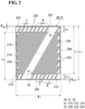
- the inclined grooves are inclined leftward and upward in the illustrated example, the inclined grooves may instead be inclined rightward and upward as illustrated in Fig. 2 .
- Each of the inclined grooves at the introduction side has one end (inlet 215) on the supply edge 200 and the other end at a position shifted in the width direction of the bipolar plate 2A (leftward and upward in Fig. 1 ) in accordance with the inclination angle ⁇ .
- the other end of each of the inclined grooves at the introduction side approaches the corner between the discharge edge 202 that opposes the supply edge 200 and one of the side edges 204 (left side edge 204 in Fig. 1 ).
- Each of the inclined grooves at the discharge side has one end (outlet 225) on the discharge edge 202 and the other end at a position shifted in the width direction of the bipolar plate 2A (rightward and downward in Fig. 1 ) in accordance with the inclination angle ⁇ .
- each of the inclined grooves at the discharge side approaches the corner between the supply edge 200 and the other of the side edges 204 (right side edge 204 in Fig. 1 ).
- regions near the corners can serve as electrolyte circulation regions.
- one end of each of the interdigitating grooves 210 at the introduction side opens at the supply edge 200, and the other end is closed at a position separated from the discharge edge 202 by a length Le in a direction orthogonal to the discharge edge 202.
- One end of each of the interdigitating grooves 220 at the discharge side is open at the discharge edge 202, and the other end is closed at a position separated from the supply edge 200 by the length Le in a direction orthogonal to the supply edge 200. Since the other end of each of the interdigitating grooves 210 and 220 is closed, the interdigitating grooves 210 at the introduction side and the interdigitating grooves 220 at the discharge side form independent flow paths.
- a region in which the interdigitating grooves 210 at the introduction side extend and which excludes the area within the length Le from the supply edge 200 at the bottom side in Fig. 1 and a region in which the interdigitating grooves 220 at the discharge side extend and which excludes the area within the length Le from the discharge edge 202 at the top side in Fig. 1 define the interdigitating region 24.
- a region of the electrode that corresponds to the interdigitating region 24 includes reaction regions on both sides of groove-facing regions that correspond to the interdigitating grooves 210 and 220. The reaction regions of the electrode are provided between the interdigitating grooves 210 and 220.
- the groove-facing regions of the electrode that face the interdigitating grooves 210 at the introduction side serve as regions through which unreacted electrolyte is received
- the groove-facing regions of the electrode that face the interdigitating grooves 220 at the discharge side serve as regions through which the reacted electrolyte is discharged.
- the reaction regions of the electrode are disposed between the regions in which the unreacted electrolyte is received and the regions in which the reacted electrolyte is discharged.
- the above-described reaction regions of the electrode can be more easily increased.
- the unreacted electrolyte can be more easily supplied to the reaction region, and the reacted electrolyte can be more easily discharged from the reaction region.
- the above-described area percentage may be, for example, 60% or more, 70% or more, or 80% or more.
- the length Le may be in the range of 5% or more and 20% or less of a length L 2 of the side edges 204, which are portions of the peripheral edge of the bipolar plate 2A that are orthogonal to the supply edge 200 or the discharge edge 202.
- the length L 2 of the side edges 204 is the length of portions of the peripheral edge of the bipolar plate 2A that extend mainly in the direction in which the electrolyte is circulated.
- the inclined grooves at the introduction side may include separate grooves 212 that are not arranged adjacent to the inclined grooves at the discharge side and do not extend to a position separated from the supply edge 200 by a predetermined length (position separated from the discharge edge 202 by the length Le at the top in this example).
- the inclined grooves at the discharge side may include separate grooves 222 that are not arranged adjacent to the inclined grooves at the introduction side and do not extend to a position separated from the discharge edge 202 by a predetermined length (position separated from the supply edge 200 by the length Le at the bottom in this example).
- relatively small regions where the interdigitating grooves 210 and 220 cannot be provided such as the regions near the lower left corner and the upper right corner in Fig. 1 , can serve as the electrolyte circulation regions.
- the electrode placed on the bipolar plate 2A receives the electrolyte through groove-facing regions corresponding to the separate grooves 212, and a battery reaction occurs in reaction regions near the groove-facing regions. The reacted electrolyte is discharged to the discharge path 22 of the bipolar plate 2A through the electrode.
- the numbers, etc., of the separate grooves 212 and 222 may be selected as appropriate.
- the separate grooves 212 at the introduction side, the separate grooves 222 at the discharge side, or both the separate grooves 212 and 222 may be omitted.
- the separate grooves 212 and 222 differ in groove length, but are the same in shape and magnitudes of, for example, the inclination angle ⁇ , the groove width W, and the groove depth. However, these parameters may differ between the separate grooves 212 and 222.
- the separate grooves 212 and 222 and the interdigitating grooves 210 and 220 differ in groove length, but are the same in shape and magnitudes of, for example, the inclination angle ⁇ . However, these parameters may differ between the separate grooves 212 and 222 and the interdigitating grooves 210 and 220. As the number of inclined grooves increases, the electrolyte can be easily uniformly supplied over a larger area of the bipolar plate 2A.
- the shape of the inclined grooves in plan view is typically a parallelogram shape as illustrated in Fig. 1 .
- the inclined grooves have a constant groove width W (length along the supply edge 200 or the discharge edge 202 in this example) over the entire length thereof in the longitudinal direction.
- W width along the supply edge 200 or the discharge edge 202 in this example
- the circulation pressure of the electrolyte does not easily vary, and the electrolyte circulation performance can be improved.
- the number of inclined grooves in the bipolar plate 2A can be easily increased and the electrolyte can be easily uniformly supplied over a large area of the bipolar plate 2A, although this also depends on the groove width W and a distance C between the inclined grooves that are adjacent to each other.
- the shape of the inclined grooves in cross section is typically a rectangular shape (not shown in this example) having a bottom side parallel to the front and back surfaces of the bipolar plate 2A.
- the volume of the inclined grooves can be easily increased, and the electrolyte circulation performance can be improved.
- the inclined grooves all have the same groove depth over the entire length thereof, and the shape of the inclined grooves in any cross section is the same as the shape of the openings at the ends of the inclined grooves. In this case, the circulation pressure of the electrolyte does not easily vary in each inclined groove.
- the electrolyte circulation performance be improved, but also the electrolyte can be easily uniformly circulated in all of the inclined grooves.
- the electrolyte circulation performance can be further improved and the electrolyte utilization rate can be further increased.
- the inclined grooves all have the same groove width W and the same groove depth, and the interdigitating grooves 210 and 220 have the same groove length.
- the bipolar plate 2A can be easily formed in a simple shape, and is highly manufacturable.
- the inclined grooves are schematically illustrated and the parameters, such as the inclination angle ⁇ , may not satisfy the ranges described below.
- the inclination angle ⁇ is in the range of or more than 0° and less than 90°.
- the rectangular bipolar plate 2A can be easily formed such that a large area including the regions near the corners thereof serves as an electrolyte circulation region by appropriately adjusting the number of inclined grooves, the groove width W, the groove length, and other parameters.
- the electrode utilization rate can be increased.
- the inclination angle ⁇ increases, the amount of shift between one and the other ends of each inclined groove in the width direction increases, and the inclined grooves can be more easily arranged in peripheral regions, such as the corners, of the bipolar plate 2A.
- the inclination angle ⁇ may be set to 1.5° or more, 2° or more, or 2.5° or more.
- the inclination angle ⁇ is 40° or less, not only can the bipolar plate 2A be formed such that a large area thereof serves as the electrolyte circulation region as described above, but also the inclined grooves have a high electrolyte circulation performance since the inclination angle is not excessively large.
- a large number of inclined grooves can be easily arranged to open at the supply edge and the discharge edge, and this also leads to an improvement in the electrolyte circulation performance.
- the inclination angle ⁇ may be set to less than 40°, 38° or less, 35° or less, 30° or less, 25° or less, or 20° or less.
- the inclination angle ⁇ may be set to satisfy a condition that when viewed from one end (inlet 215 or outlet 225) of each inclined groove, the other end is shifted by a distance greater than or equal to the groove width W of the inclined grooves.
- the inclination angle ⁇ is relatively large, so that the electrolyte circulation region on the bipolar plate 2A can be easily increased and that the electrode utilization rate can be increased accordingly, although this also depends on the groove width W.
- the above-described shift in the width direction may be greater than or equal to 1.2 times the groove width W, greater than or equal to 1.5 times the groove width W, or greater than or equal to twice the groove width W.
- the groove width W may be, for example, about 0.5% or more and 5% or less, or about 0.5% or more and 2% or less, of the length W 2 of the supply edge 200 or the discharge edge 202 of the bipolar plate 2A.
- the groove width W may be 0.1 mm or more and 10 mm or less, 0.1 mm or more and 8 mm or less, 0.1 mm or more and 5 mm or less, or 0.5 mm or more and 3 mm or less.
- the groove width W increases, the circulation resistance of the electrolyte that flows along the inclined grooves decreases, so that a reduction in the pressure loss can be expected.
- the groove width W decreases, the number of inclined grooves can be easily increased, and the electrolyte can be easily uniformly supplied over a larger area of the bipolar plate 2A.
- the groove depth may be, for example, about 10% or more and 45% or less of the thickness of the bipolar plate 2A.
- the groove depth is in this range, even in the case where the front and back surfaces of the bipolar plate 2A each have a flow passage (in this case, the flow passage on at least one of the surfaces is the flow passage 20 including the inclined grooves), the mechanical strength of the bipolar plate 2A is not easily reduced, and the bipolar plate 2A has a sufficient strength.
- the groove depth is 10% or more and 35% or less of the thickness of the bipolar plate 2A, the strength of the bipolar plate 2A can be further increased.
- the groove length may be set as appropriate in accordance with, for example, the inclination angle ⁇ and the size of the bipolar plate 2A. As the groove length increases, the length of the reaction regions of the electrode can be easily increased, and a higher battery reactivity can be expected.
- the inclined grooves may include an inclined groove formed such that, in an imaginary right triangle having the inclined groove as a hypotenuse and an interior angle equal to the inclination angle ⁇ , the side that forms the inclination angle ⁇ between itself and the inclined groove has a length of 80% or more and 95% or less, or 85% or more and 90% or less, of the length L 2 of the side edges 204.
- the distance C between the inclined grooves may be, for example, about 1 mm or more and 10 mm or less, or about 1.5 mm or more and 5 mm or less. As the distance C increases, the reaction regions of the electrode can be easily increased. As the distance C decreases, the number of inclined grooves can be easily increased, and the electrolyte can be easily uniformly supplied over a larger area of the bipolar plate 2A.
- Figure 1 illustrates a configuration in which the distance between the inclined grooves at the introduction side and the distance between inclined grooves at the discharge side are both (2 ⁇ C + groove width W) in the interdigitating region 24.
- the frame body 120 of the cell frame 12 includes a pair of frame pieces that support the bipolar plate by clamping the peripheral portion of the bipolar plate therebetween, the peripheral portion of the bipolar plate is covered by portions of the frame pieces near the inner peripheral edges of the frame pieces.
- the bipolar plate 2A may have flow passages (flow passage on at least one surface is the flow passage 20 including the inclined grooves) in a region exposed at a window portion of the frame body 120.
- the bipolar plate 2A may have no flow passages on the portion thereof covered by the frame body 120.
- the bipolar plate 2A may have a configuration ( ⁇ ) in which one of the front and back surfaces has the flow passage 20 including the inclined grooves and in which the other surface is flat and has no flow passage; a configuration ( ⁇ 1) in which both surfaces have electrolyte flow passages, the flow passage on one surface being the flow passage 20 including the inclined grooves and the flow passage on the other surface including no inclined grooves; and a configuration ( ⁇ 2) in which each of the surfaces has the flow passage 20 including the inclined grooves.
- the flow passage on the other surface may include, for example, the above-described vertical and horizontal grooves.
- This bipolar plate 2A is configured such that, in a see-through plan view of the front and back surfaces, the inclined grooves provided on one surface intersect the vertical and horizontal grooves included in the flow passages on the other surface.
- the configuration ( ⁇ 2) when at least one of the inclination direction and the inclination angle differs between the inclined grooves on the front surface and the inclined grooves on the back surface, the inclined grooves provided on one surface intersect the inclined grooves provided on the other surface in a see-through plan view of the front and back surfaces of the bipolar plate 2A (this configuration may hereinafter be referred to as a configuration ⁇ 2-1).
- the configuration ( ⁇ 2-1) may be a configuration in which the inclined grooves on one and the other surfaces have the same inclination angle and different inclination directions, a configuration in which the inclined grooves on one and the other surfaces have the same inclination direction and different inclination angles, or a configuration in which the inclined grooves on one and the other surfaces have different inclination angles and different inclination directions.
- the configuration ( ⁇ 2) may instead be a configuration ( ⁇ 2-2) in which the inclined grooves have the same inclination angle and the same inclination direction and substantially do not intersect.
- the flow passages 20 on the front and back surfaces may have the same specifications so that inclined grooves on one surface of the bipolar plate 2A and the inclined grooves on the other surface of the bipolar plate 2A completely overlap in a see-through plan view.
- the inclined grooves on one surface of the bipolar plate 2A and the inclined grooves on the other surface of the bipolar plate 2A may be shifted from each other so that at least portions thereof do not overlap in a see-through plan view. In this case, the regions in which the grooves on the front and back surfaces overlap can be reduced, so that the strength of the bipolar plate 2A can be easily increased.
- the flow passage 20 provided on at least one of the front and back surfaces preferably has the interdigitating region 24 as in this example.
- the discussions regarding the flow passages on the front and back surfaces also apply to the second embodiment described below.
- An electrically conductive material having a low electrical resistance that does not react to the electrolyte and that is resistant to electrolyte (resistant to chemicals, acids, etc.) is suitable for use as the material of the bipolar plate 2A according to the embodiment.
- the material preferably has an appropriate rigidity so that the shape and dimensions of the grooves that form the flow passage 20 do not easily vary for a long time and the effects of the flow passage 20 (for example, improvement in the electrode utilization rate, reduction in the circulation resistance, and reduction in loss, such as pump loss) can be reliably obtained.
- the material examples include a composite material containing a carbon material and an organic material. More specifically, the material may be an electrically conductive plastic containing an electrically conductive inorganic material, such a graphite, and an organic material, such as a polyolefin-based organic compound or a chlorinated organic compound.
- the bipolar plate 2A including the flow passage 20 may be manufactured by forming the above-described material into a plate shape by a commonly known method, such as injection molding, press forming, or vacuum forming, and forming the flow passage 20.
- the bipolar plate 2A is highly manufacturable when the flow passage 20 is formed at the same time.
- the flow passage 20 may instead be formed by cutting a flat-plate-shaped material having no flow passage 20.
- the bipolar plate 2A according to the first embodiment includes specific inclined grooves (210, 220, 212, and 222), the regions near the corners thereof, for example, can serve as the electrolyte circulation regions, and the overall circulation region can be increased. Accordingly, the bipolar plate 2A of the first embodiment provides an increase in the electrode utilization rate when included in an RF battery.
- the introduction path 21 and the discharge path 22 on the bipolar plate 2A of this example both have the inclined grooves. This also contributes to an increase in the circulation region and an increase in the electrode utilization rate.
- the bipolar plate 2A of this example includes a large number of inclined grooves (including the separate grooves 212 and 222), and this also contributes to an increase in the electrode utilization rate.
- the bipolar plate 2A according to the first embodiment is configured such that the introduction path 21 and the discharge path 22 do not communicate with each other. Accordingly, when an electrode is placed on the bipolar plate 2A, the electrode receives the electrolyte from the introduction path 21 in the groove-facing regions corresponding to the introduction path 21, causes a battery reaction in the reaction regions that are near the groove-facing regions (on both sides of the groove-facing regions in this example), and then discharges the reacted electrolyte from the reaction regions to the discharge path 22 of the bipolar plate 2A through the groove-facing regions corresponding to the discharge path 22.
- the bipolar plate 2A according to the first embodiment enables an efficient use of the electrolyte for the battery reaction when included in an RF battery.
- the bipolar plate 2A of this example is configured such that the introduction path 21 and the discharge path 22 include the inclined grooves (interdigitating grooves 210 and 220) arranged to interdigitate with each other. Therefore, the electrolyte can be efficiently used for the battery reaction.
- the bipolar plate 2A of this example is highly manufacturable because the inclined grooves open at the supply edge 200 and the discharge edge 202 of the bipolar plate 2A.
- the bipolar plate 2B according to the second embodiment will now be described with reference to Fig. 2 .
- the basic structure of the bipolar plate 2B according to the second embodiment is similar to that of the bipolar plate 2A according to the first embodiment, and a flow passage 20 including an introduction path 21 and a discharge path 22 is provided on a surface of the bipolar plate 2B that faces an electrode. At least one of the introduction path 21 and the discharge path 22 includes inclined grooves (210, 212, 220, and 222).
- the bipolar plate 2B according to the second embodiment mainly differs from that of the first embodiment in that the introduction path 21 includes a distributing groove 214, the discharge path 22 includes a collecting groove 224, and the inclination angle ⁇ is relatively large.
- the distributing groove 214 extends along a portion of the peripheral edge of the bipolar plate 2B including a supply edge 200, and opens at this portion of the peripheral edge.
- the collecting groove 224 extends along a portion of the peripheral edge of the bipolar plate 2B including a discharge edge 202, and opens at this portion of the peripheral edge.
- the bipolar plate 2B of the second embodiment includes the distributing groove 214 and the collecting groove 224 that are configured such that some of the inclined grooves that are separated from the supply edge 200 and the discharge edge 202 and disposed near the side edges 204, 204 receive the electrolyte from the distributing groove 214 and discharge the electrolyte to the collecting groove 224.
- the distributing groove 214 which forms a portion of the introduction path 21, is an L-shaped groove including a supply-edge portion that extends along the supply edge 200 of the bipolar plate 2B and opens at the supply edge 200 and a side-edge portion that extends along a corresponding side edge 204 and opens at the side edge 204.
- the inclined grooves disposed near the side edge 204 are each connected to the side-edge portion of the distributing groove 214 at one end thereof. Therefore, the electrolyte can be supplied to each of the inclined grooves disposed near the side edge 204 through the distributing groove 214.
- the supply-edge portion of the distributing groove 214 may have a length shorter than that of the supply edge 200.
- some of the inclined grooves that are disposed near the supply edge 200 may open at the supply edge 200 while the other inclined grooves open at the supply-edge portion.
- all of the inclined grooves disposed near the supply edge 200 may open at the supply edge 200 so that no inclined grooves are connected to the supply-edge portion of the distributing groove 214.
- the supply-edge portion may serve also as a rectifying groove. In this case, it is not necessary that the frame body 120 include a rectifying groove.
- the collecting groove 224 which forms a portion of the discharge path 22, is an L-shaped groove including a discharge-edge portion that extends along the discharge edge 202 of the bipolar plate 2B and opens at the discharge edge 202 and a side-edge portion that extends along a corresponding side edge 204 and opens at the side edge 204.
- the collecting groove 224 opens along portions (discharge edge 202 and right side edge 204) of the peripheral edge of the bipolar plate 2B that oppose the portions (supply edge 200 and left side edge 204) along which the distributing groove is provided.
- the inclined grooves disposed near the side edge 204 are each connected to the side-edge portion of the collecting groove 224 at one end thereof. Therefore, the electrolyte from each of the inclined grooves disposed near the side edge 204 can be collected and discharged through the collecting groove 224.
- the discharge path 22 illustrated in Fig. 2 includes both the inclined grooves connected to the side-edge portion and the inclined grooves connected to the discharge-edge portion, and all of these inclined grooves open in the collecting groove 224.
- the discharge-edge portion of the collecting groove 224 may have a length shorter than that of the discharge edge 202.
- some of the inclined grooves that are disposed near the discharge edge 202 may open at the discharge edge 202 while the other inclined grooves open at the discharge-edge portion.
- all of the inclined grooves disposed near the discharge edge 202 may open at the discharge edge 202 so that no inclined grooves are connected to the discharge-edge portion of the collecting groove 224.
- the discharge-edge portion may serve also as a rectifying groove. In this case, it is not necessary that the frame body 120 include a rectifying groove.
- the groove widths W 214 and W 224 , the groove depths, the groove lengths (lengths of the supply-edge portion and the discharge-edge portion along the supply edge 200 and the discharge edge 202, respectively, and the length L 4 of the side-edge portions along the side edges 204), etc., of the distributing groove 214 and the collecting groove 224 may be set as appropriate.
- the lengths of the supply-edge portion and the discharge-edge portion may be set in the range of less than or equal to the length W 2 of the supply edge 200 and the discharge edge 202, and may be W 2 as in this example, or be, for example, 5% or more and 10% or less, or 5% or more and 8% or less, of the length W 2 .
- the length L 4 may be set in the range of less than the length L 2 of the side edges 204, and may be, for example, 80% or more and 95% or less, or 85% or more and 90% or less, of the length L 2 .
- the groove widths W 214 and W 224 and the groove depths may be set as in the description regarding the inclined grooves. At least one of the groove width W 214 , W 224 , the groove depth, and the groove length may differ between the distributing groove 214 and the collecting groove 224. However, when the distributing groove 214 and the collecting groove 224 have the same groove width, the same groove depth, and the same groove length as in this example, the bipolar plate 2B can be easily formed in a simple shape, and is highly manufacturable.
- the bipolar plate 2B according to the second embodiment includes specific inclined grooves (210, 220, 212, and 222), and therefore provides an increase in the electrode utilization rate when included in an RF battery.
- the bipolar plate 2B according to the second embodiment includes the introduction path 21 and the discharge path 22 that are independent of each other, and therefore enables an efficient use of the electrolyte for the battery reaction when included in an RF battery.
- the bipolar plate 2B according to the second embodiment is configured such that the inclination angle ⁇ of the inclined grooves is relatively greater than that in the bipolar plate 2A according to the first embodiment, and includes the distributing groove 214 and the collecting groove 224.
- the bipolar plate 2B includes the inclined grooves connected to the distributing groove 214 and the inclined grooves connected to the collecting groove 224.
- the electrolyte can be supplied to the inclined grooves at the introduction side (interdigitating grooves 210 in this example) through the distributing groove 214, and discharged from the inclined grooves at the discharge side (interdigitating grooves 220 in this example) through the collecting groove 224.
- the electrolyte can be smoothly introduced and discharged not only through the inclined grooves that open at the supply edge 200 and the discharge edge 202 but also through the inclined grooves disposed near the side edges 204.
- the above-described bipolar plate 2B according to the second embodiment enables an efficient use of the electrolyte for the battery reaction when included in an RF battery.
- the inclination angle ⁇ of the inclined grooves is as large as, for example, 1° or more, the number of inclined grooves can be easily increased by forming the distributing groove 214 and the collecting groove 224.
- the inclined grooves may be arranged to serve as the interdigitating grooves 210 and 220, so that the interdigitating region 24 can be increased. As a result, the electrolyte can be efficiently used for the battery reaction.
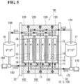
- ions shown in a positive electrolyte tank 16 and a negative electrolyte tank 17 are examples of types of ions contained in positive and negative electrolytes.
- the solid line arrows represent a charging operation
- the broken line arrows represent a discharging operation.
- the RF battery 10 is a single-cell battery ( Fig. 3 ) or a multi-cell battery ( Figs. 4 and 5 ) including bipolar plates 2 that are each provided with the flow passage 20 ( Fig. 4 ) including the specific inclined grooves described in the first and second embodiments.
- the cell stack 30 according to the embodiment includes the bipolar plates 2 that are each provided with the flow passage 20 ( Fig. 4 ) including the specific inclined grooves described in the first and second embodiments, and is included in a multi-cell battery.
- the structures of the RF battery 10 and the cell stack 30 will now be described.
- the RF battery 10 includes a battery cell 10C and a circulation mechanism that circulates the electrolyte through the battery cell 10C.
- the RF battery 10 is connected to a power generator 420 and load 440, such as a power system or a consumer, through, for example, an alternating current/direct current converter 400 and a transformer facility 410.
- the RF battery 10 is charged with electricity with the power generator 420 serving as an electric power source, and discharges electricity to supply electric power to the load 440.
- the power generator 420 is, for example, a solar photovoltaic power generator, a wind power generator, or a common power station.
- the battery cell 10C includes a positive electrode 14 to which positive electrolyte is supplied, a negative electrode 15 to which negative electrolyte is supplied, a membrane 11 interposed between the positive electrode 14 and the negative electrode 15, and a pair of bipolar plates 2, 2 between which the positive electrode 14 and the negative electrode 15, which have the membrane 11 therebetween, is disposed.
- the positive electrode 14 and the negative electrode 15 serve as reaction fields to which the electrolytes containing active materials are supplied and in which battery reactions of the active materials (ions) occur, and are composed of, for example, porous materials, such as fiber aggregates of carbon materials.
- the membrane 11 is a member that separates the positive electrode 14 and the negative electrode 15 from each other and transmits predetermined ions, and is composed of, for example, an ion-exchange membrane.
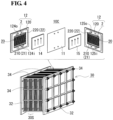
- the battery cell 10C typically includes cell frames 12 illustrated in Fig. 4 .
- Each cell frame 12 includes the bipolar plate 2 and a frame body 120 formed along the outer periphery of the bipolar plate 2.
- a single-cell battery including a single battery cell 10C includes a single pair of cell frames 12, 12.
- a multi-cell battery including a plurality of battery cells 10C includes a plurality of pairs of cell frames 12.
- the multi-cell battery may include a plurality of bipolar plates 2 which each have one surface facing a positive electrode 14 and the other surface facing a negative electrode 15 and which are each typically provided with a positive-electrolyte flow passage on one surface and a negative-electrolyte flow passage on the other surface.
- each bipolar plate 2 in plan view is rectangular in Fig. 4
- the bipolar plate 2 may have any appropriate shape in plan view.
- Figure 4 illustrates an example in which each bipolar plate is the bipolar plate 2A according to the first embodiment having the flow passage 20 that includes the inclined grooves serving as the interdigitating grooves 210 and 220 and that does not include the distributing groove 214 and the collecting groove 224.
- Each frame body 120 is a member that supports the corresponding bipolar plate 2 and is used to supply the electrolytes to the electrodes placed on the bipolar plate 2 and discharge the electrolytes from the electrodes.
- Figure 4 illustrates rectangular frames which each have a rectangular window portion (through hole) at the center thereof as an example.
- the frame body 120 is made of, for example, a resin that is highly resistant to electrolyte and electrically insulating.
- the frame body 120 has supply paths and discharge paths for the electrolytes.
- the supply paths include electrolyte inlets (124i for the positive electrolyte and 125i for the negative electrolyte) and slits that extend from the electrolyte inlets to the window portion.
- the discharge paths include electrolyte outlets (124o for the positive electrolyte and 125o for the negative electrolyte) and slits that extend from the window portion to the electrolyte outlets.
- the bipolar plate 2 is arranged such that the supply edge 200 ( Figs. 1 and 2 ) thereof is in contact with a portion of the inner peripheral edge of the frame body 120 that is connected to the above-described supply paths and the discharge edge 202 thereof is in contact with a portion of the inner peripheral edge of the frame body 120 that is connected to the above-described discharge paths.
- Rectifying grooves may be provided in an inner peripheral region that extends along the inner peripheral edge of the frame body 120 and that is between the peripheral edge of the window portion and the above-described slits.
- supply-side rectifying grooves may be provided along the bottom edge of the window portion
- discharge-side rectifying grooves may be provided along the top edge of the window portion.
- the bipolar plate 2 may have rectifying grooves (not shown) that extend along the peripheral edge of the bipolar plate 2 in place of the rectifying grooves in the frame body 120.
- the cell stack 30 includes a layered body in which a plurality of cell frames 12 (bipolar plates 2), a plurality of positive electrodes 14, a plurality of membranes 11, and a plurality of negative electrodes 15 are arranged in a certain order and stacked together; a pair of end plates 32, 32 that clamp the layered body; connecting members 34, such as long bolts, that connect the end plates 32, 32; and fastening members, such as nuts.
- the end plates 32, 32 are tightened by the fastening members, the layered body is retained in the layered state by a tightening force applied in the stacking direction.
- the cell stack 30 may be configured to include a plurality of sub-cell stacks 30S that are stacked together, each sub-cell stack 30S including a predetermined number of battery cells 10C.
- the cell frames on both ends of the sub-cell stack 30S or the cell stack 30 in the direction in which the battery cells 10C are stacked each have a current collector plate including the bipolar plate 2.
- the frame bodies 120, 120 that are adjacent to each other have sealing members disposed therebetween so that the layered body is liquid-tight.
- the circulation mechanism includes the positive electrolyte tank 16 storing the positive electrolyte to be circulated and supplied to each positive electrode 14, the negative electrolyte tank 17 storing the negative electrolyte to be circulated and supplied to each negative electrode 15, pipes 162 and 164 that connect the positive electrolyte tank 16 to each battery cell 10C (cell stack 30), pipes 172 and 174 that connect the negative electrolyte tank 17 to each battery cell 10C (cell stack 30), and the pumps 160 and 170 provided on the pipes 162 and 172 through which the electrolytes are supplied to each battery cell 10C.
- the pipes 162, 164, 172, and 174 are connected to electrolyte circulation passages formed of the electrolyte inlets 124i and 125i and the electrolyte outlets 124o and 125o in the cell frames 12 that are stacked, thereby forming circulation circuits for the positive and negative electrolytes.
- the RF battery 10 and the cell stack 30 may have commonly known basic structures, materials, etc., as appropriate. Also, commonly known electrolytes may be used as appropriate.
- the pair of bipolar plates 2, 2 included in the battery cell 10C is provided with the above-described flow passage 20 including the inclined grooves on a surface thereof that faces an electrode.
- the pair of bipolar plates 2, 2 may be configured such that only one of the bipolar plates 2 is provided with the flow passage 20 including the inclined grooves.
- the bipolar plates 2, 2 are preferably both provided with the flow passage 20 including the inclined grooves since the utilization rate of both the positive and negative electrodes 14 and 15 can be increased in such a case.
- the bipolar plates 2 may be formed such that the flow passage 20 is provided on both the front and back surfaces thereof.
- the multi-cell battery according to the embodiment includes a plurality of bipolar plates 2 that are each provided with a flow passage on the front and back surfaces thereof.
- These bipolar plates 2 may each have the configuration ( ⁇ 1) in which the inclined grooves are provided on only one surface thereof or the configuration ( ⁇ 2) in which the inclined grooves are provided on both surfaces thereof.
- a bipolar plate 2 having the configuration ( ⁇ 2-1) in which the inclined grooves on one and the other surfaces intersect in a see-through plan view is preferably provided because the utilization rate of both the positive and negative electrodes 14 and 15 can be increased in such a case.
- the bipolar plate 2 having the configuration ( ⁇ 2-1) may be provided with, for example, the flow passage 20 including the inclined grooves that are inclined leftward and upward as illustrated in Fig.
- the regions in which the grooves overlap in a see-through plan view of the front and back surfaces of the bipolar plate 2 can be reduced. Intersecting regions in which the grooves intersect may be the only regions in which the grooves overlap, although this also depends on the inclination angle ⁇ , the groove width W, and the distance C ( Figs. 1 and 2 ). Therefore, the positive electrolyte that flows along the inclined grooves on one surface of this bipolar plate 2 and the negative electrolyte that flows along the inclined grooves on the other surface flow in different regions except for the above-described intersecting regions.
- the electrolyte circulation performance can be improved for both the positive and negative electrolytes.
- a reduction in loss such as pump loss
- the reaction regions of the positive electrode 14 and the negative electrode 15, between which the bipolar plate 2 is disposed can be shifted from each other. Accordingly, the battery reactions easily occur, and an increase in the electrolyte utilization rate can be expected.
- the bipolar plate 2 can be easily configured to have a sufficient strength, and the number of inclined grooves can be increased. Therefore, according to this bipolar plate 2, it can be expected that the electrolyte can be easily uniformly supplied over a large area and that the electrode utilization rate can be easily increased.
- the bipolar plates 2 that are arranged to face each other are preferably configured such that at least one of the flow passage provided on a surface of one of the bipolar plates 2 (left bipolar plate 2 in Fig. 4 ) that faces the positive electrode 14 and the flow passage provided on a surface of the other bipolar plate 2 (right bipolar plate 2 in Fig. 4 ) that faces the negative electrode includes the inclined grooves, and such that the inclined grooves included in one of the flow passages intersect the grooves included in the other flow passage. According to this configuration, the regions in which the grooves overlap in a see-through plan view of the pair of bipolar plates 2, 2 can be reduced.
- Intersecting regions in which the grooves intersect may be the only regions in which the grooves overlap, although this also depends on the inclination angle ⁇ , the groove width W, and the distance C ( Figs. 1 and 2 ). Therefore, one of the electrolytes that flows along the inclined grooves on one of the bipolar plates 2 and the other electrolyte that flows along the grooves included in the flow passages on the other bipolar plate 2 flow along the surfaces that face each other in different regions except for the above-described intersecting regions. Thus, the electrolyte circulation performance can be improved for both the positive and negative electrolytes. As a result, a further reduction in loss, such as pump loss, can be expected.
- one of the bipolar plates 2 may include the inclined grooves while the other bipolar plate 2 includes the above-described vertical grooves and horizontal grooves.
- the bipolar plates 2 both include the inclined grooves, and the inclined grooves on one of the bipolar plates 2 intersect the inclined grooves on the other bipolar plate 2. In such a case, not only the electrolyte circulation performance and the electrolyte utilization rate, but also the electrode utilization rate can be increased.
- the shapes of the grooves that form the flow passages on the pair of bipolar plates 2, 2 and the inclination direction, the inclination angle, etc., of the inclined grooves may be set so that the grooves that form the flow passages intersect when the bipolar plates 2 are arranged to face each other.
- the pair of bipolar plates 2 arranged to face each other have the configuration ( ⁇ 1) or ( ⁇ 2-1), in which the grooves that form the flow passages on both surfaces intersect in a see-through plan view, the positions, for example, of the bipolar plates 2 may be adjusted so that the grooves on the surfaces that face each other intersect.
- the bipolar plates 2 that are arranged to face each other may instead be configured such that the inclined grooves provided on a surface of one of the bipolar plates 2 that faces the positive electrode 14 and the inclined grooves provided on a surface of the other bipolar plate 2 that faces the negative electrode have the same inclination direction and the same inclination angle and substantially do not intersect.
- the inclined grooves on one of the bipolar plates 2 that face each other and the inclined grooves on the other bipolar plate 2 are shifted from each other so that at least portions of the inclined grooves do not overlap, the above-described regions in which the inclined grooves overlap can be reduced, and the electrolyte circulation performance can be increased.
- the number of inclined grooves tends to be reduced, and a reduction in the electrode utilization rate easily occurs. Therefore, the above-described configuration in which the grooves that face each other intersect is more preferable.
- the RF battery 10 according to the embodiment includes the bipolar plates 2 (2A, 2B, etc.) according to the embodiment, and therefore has a high electrode utilization rate. As a result, the RF battery 10 has a low internal resistance and a high battery efficiency. This effect will be further described in Test Example 1.
- the RF battery 10 includes the bipolar plates 2 which are each provided with the flow passage 20, and therefore has a high electrolyte circulation performance and low loss, for example, low pump loss.
- the cell stack 30 according to the embodiment includes the bipolar plates 2 (2A, 2B, etc.) according to the embodiment, and therefore has a high electrode utilization rate. Accordingly, an RF battery having a low internal resistance and a high battery efficiency or an RF battery with low loss, for example, low pump loss, can be formed by using the cell stack 30.
- Bipolar plates including inclined grooves having various inclination angles ⁇ were prepared, and RF batteries including the bipolar plates were manufactured. The internal resistance and current efficiency of each RF battery were determined.
- the specifications of the bipolar plates used in this test are given below.
- the shape of the prepared bipolar plates was generally close to that of the bipolar plate 2B illustrated in Fig. 2 .
- the prepared bipolar plates each had the inclined grooves on both the front and back surfaces thereof.
- the bipolar plates were configured such that the inclined grooves on the front and back surfaces thereof had the same inclination angle ⁇ and different inclination directions so that the inclined grooves on the front and back surfaces intersect in see-through plan views of the bipolar plates.
- These bipolar plates were used to form RF batteries (Samples No. 1 to No. 7).
- rectangular bipolar plates having the same size (18 cm ⁇ 15 cm) and including vertical grooves, that is, grooves with an inclination angle of 0°, were prepared, and used to form an RF battery (Sample No. 100).
- These bipolar plates do not include the inclined grooves, the distributing groove, or the collecting groove, and includes vertical grooves at the introduction side that open at the supply edge and that extend in a direction orthogonal to the supply edge, and vertical grooves at the discharge side that open at the discharge edge, that extend in a direction orthogonal to the discharge edge, and that are independent of the vertical grooves at the introduction side.
- the vertical grooves at the introduction side and the vertical grooves at the discharge side are alternately arranged in an interdigitating region.
- the width of the vertical grooves was 1 mm
- the depth of the vertical grooves was 1 mm
- the distance between the grooves was 2 mm
- the length of the interdigitating region in the long-side direction was 17 cm
- the length of the regions provided outside the interdigitating region at the introduction side and the discharge side was 5 mm.
- a single-cell battery and a multi-cell battery were both prepared as the batteries of the comparative example.
- the prepared RF batteries were subjected to a charge-discharge test at a constant current (54 A in this example).
- vanadium-based electrolytes were used, and the temperature of the electrolytes was set to 35°C.
- the flow rates of the positive and negative electrolytes were both set to 0.7 L/min, and the RF batteries were charged and discharged for three cycles.
- the charge voltage and the discharge voltage were measured for two of the three cycles excluding the first cycle, and the cell resistance ( ⁇ cm 2 /cell) was determined by using the average charge voltage and the average discharge voltage of the two cycles. The results are shown in Fig. 6 and Table 1.
- Samples Nos. 1 to 7 are the RF batteries including the rectangular bipolar plates having the inclined grooves that non-orthogonally intersect the long and short sides of the bipolar plates.
- Sample No. 100 is the RF battery including the rectangular bipolar plates having the vertical grooves that extend parallel to the long sides of the bipolar plates and orthogonal to the short sides of the bipolar plates. This configuration is similar to the vertical groove configuration according to the related art.
- Figure 6 and Table 1 show that the RF batteries of Samples Nos. 1 to 7 including the above-described inclined grooves have cell resistances less than that of the RF battery of Sample No. 100 including the vertical grooves.
- the cell resistance can be reduced when the inclination angle ⁇ of the inclined grooves is 1° or more.
- the inclination angle ⁇ is greater, in particular, 3° or more, 10° or more, or more than 10°, the cell resistance can be more easily reduced.
- the inclination angle ⁇ is 40° or less, in particular, less than 40°, or 35° or less, the cell resistance can be more easily reduced.
- Figure 6 and Table 1 also show that the RF batteries of Nos. 1 to 7 have battery efficiencies higher than that of the RF battery of Sample No. 100 including the vertical grooves.
- the battery efficiency can be increased when the inclination angle ⁇ is 1° or more.
- the inclination angle ⁇ is greater, in particular, 3° or more, 10° or more, or more than 10°, the battery efficiency can be more easily increased.
- the inclination angle ⁇ is 40° or less, the battery efficiency tends to be high. Therefore, the inclination angle ⁇ of the inclined grooves is preferably 1° or more and less than 40° in terms of cell resistance and battery efficiency.
- At least one of the modifications described below may be applied to the bipolar plate 2 according to the embodiment, the RF battery 10 according to the embodiment, or the cell stack 30 according to the embodiment.
- the interdigitating grooves 210 and 220 may each be formed of a group including a plurality of groove pieces arranged in the inclination direction with gaps therebetween.
- regions surrounding the groove-facing regions may be used as the reaction regions. Therefore, the reaction regions can be increased, and high battery reactivity can be expected.
- the grooves arranged on the extension line may be regarded as belonging to a group of grooves that form a single inclined groove at the introduction side.
- the grooves arranged on the extension line may be regarded as belonging to a group of grooves that form a single inclined groove at the discharge side.
Description
- The present invention relates to a bipolar plate, a cell stack, and a redox flow battery. The present application claims priority based on "
Japanese Patent Application No. 2016-238041" filed on December 7, 2016 - A redox flow battery (hereinafter may be referred to as an RF battery) described in PTL 1 is an example of a large-capacity storage battery. The main component of the RF battery is a battery cell including a positive electrode to which positive electrolyte is supplied, a negative electrode to which negative electrolyte is supplied, and a membrane interposed between the positive and negative electrodes. The positive and negative electrolytes are supplied to the positive and negative electrodes to charge and discharge the battery (see Fig. 18 of PTL 1). A single battery cell includes a pair of bipolar plates arranged to sandwich a multilayer body including the positive and negative electrodes provided on the front and back sides of the membrane (see Fig. 19 in PTL 1). A multi-cell battery, which includes a plurality of battery cells that are stacked together, has a structure called a cell stack (Fig. 19 of PTL 1) in which a single bipolar plate has a positive electrode and a negative electrode placed on the front and back sides thereof.
- According to PTL 1, electrolyte flow passages which each include a plurality of groove portions are provided on the front and back surfaces of a square bipolar plate. Among the four sides that define the peripheral edge of the bipolar plate, the bottom side is defined as a supply edge at which electrolyte is supplied and the top side, which opposes the bottom side, is defined as a discharge edge at which the electrolyte is discharged. The bipolar plate disclosed in PTL 1 has an electrolyte flow passage on each surface thereof, the electrolyte flow passage including horizontal grooves that are parallel to the supply edge, a plurality of vertical grooves that extend from the horizontal grooves in a direction orthogonal to the horizontal grooves and that are arranged parallel to each other, and short vertical grooves that extend from the horizontal grooves and open at the supply edge or the discharge edge of the bipolar plate (
Fig. 1 in PTL 1). - PTL 1:
Japanese Unexamined Patent Application Publication No. 2015-122230 - A bipolar plate according to the present disclosure is arranged to face an electrode along which electrolyte is circulated, and includes a flow passage that is provided on at least one of front and back surfaces of the bipolar plate and along which the electrolyte is circulated. The flow passage provided on the at least one of the front and back surfaces of the bipolar plate includes an introduction path along which the electrolyte is introduced and a discharge path that does not communicate with and is independent of the introduction path and along which the electrolyte is discharged. At least one of the introduction path and the discharge path includes an inclined groove that non-orthogonally intersects a long side and a short side of an imaginary rectangle that includes an outer edge of the bipolar plate.
- Another bipolar plate according to the present disclosure is arranged to face an electrode along which electrolyte is circulated, and includes a flow passage that is provided on each of front and back surfaces of the bipolar plate and along which the electrolyte is circulated. The flow passage provided on at least one of the front and back surfaces of the bipolar plate includes an introduction path along which the electrolyte is introduced and a discharge path that does not communicate with and is independent of the introduction path and along which the electrolyte is discharged. At least one of the introduction path and the discharge path includes an inclined groove that non-orthogonally intersects a long side and a short side of an imaginary rectangle that includes an outer edge of the bipolar plate. The bipolar plate includes a pair of grooves arranged to intersect in a see-through plan view of the front and back surfaces of the bipolar plate, the pair of grooves including the inclined groove provided on one surface of the bipolar plate and a groove that forms the flow passage on another surface of the bipolar plate.
- A cell stack according to the present disclosure includes the above-described bipolar plate according to the present disclosure.
- A redox flow battery according to the present disclosure includes the above-described cell stack according to the present disclosure.
-
- [
Fig. 1] Figure 1 is a schematic plan view of a bipolar plate according to a first embodiment. - [
Fig. 2] Figure 2 is a schematic plan view of a bipolar plate according to a second embodiment. - [
Fig. 3] Figure 3 illustrates the basic structure and the basic operation principle of a redox flow battery according to an embodiment. - [
Fig. 4] Figure 4 is a schematic diagram illustrating an example of a cell stack according to an embodiment. - [
Fig. 5] Figure 5 is a schematic diagram illustrating a redox flow battery according to an embodiment that includes the cell stack. - [
Fig. 6] Figure 6 is a graph showing the relationships between the inclination angle of inclined grooves on a bipolar plate and the cell resistivity and between the inclination angle and the battery efficiency for each sample of the redox flow battery measured in Test Example 1. - Redox flow batteries with an increased electrode utilization rate are desired.
- The above-described horizontal and vertical grooves have a predetermined length that is shorter than the length of each side of the bipolar plate, and the short vertical grooves are additionally provided. Thus, the vertical and horizontal grooves are separated from the peripheral edge of the bipolar plate. The bipolar plate has no groove portions at and near the corners thereof. When, for example, a square electrode is placed on the bipolar plate, electrolyte cannot be easily supplied to the regions at and near the corners of the electrode through the flow passage of the bipolar plate. Accordingly, it is conceivable that a battery reaction does not occur in the regions at and near the corners of the electrode and that the electrolyte cannot be easily discharged from the regions at and near the corners of the electrode through the flow passage. In other words, the electrode may have regions that are not effectively utilized (regions at and near the corners in the above-described case).
- Accordingly, an object is to provide a bipolar plate with which an electrode utilization rate can be increased. Another object is to provide a cell stack and a redox flow battery having an increased electrode utilization rate.
- The electrode utilization rate can be increased by using the above-described bipolar plates of the present disclosure. The above-described cell stack according to the present disclosure and the above-described redox flow battery according to the present disclosure have high electrode utilization rates.
- Embodiments of the invention of the present application will be described.
- (1) A bipolar plate according to an embodiment of the present disclosure is arranged to face an electrode along which electrolyte is circulated, and includes a flow passage that is provided on at least one of front and back surfaces of the bipolar plate and along which the electrolyte is circulated. The flow passage provided on the at least one of the front and back surfaces of the bipolar plate includes an introduction path along which the electrolyte is introduced and a discharge path that does not communicate with and is independent of the introduction path and along which the electrolyte is discharged. At least one of the introduction path and the discharge path includes an inclined groove that non-orthogonally intersects a long side and a short side of an imaginary rectangle that includes an outer edge of the bipolar plate.
- Here, the "introduction path" is any groove portion that forms the flow passage and that satisfies any of conditions (α) to (γ) given below.
- (α) One end of the groove portion opens at a portion of the peripheral edge of the bipolar plate at which the electrolyte is supplied (supply edge).
- (β) One end of the groove portion is connected to a distributing groove described below.
- (γ) The groove portion does not open at the supply edge nor is it connected to the distributing groove, and the distance from one end of the groove portion to the supply edge or the distributing groove is shorter than the distance from the other end of the groove portion to a discharge edge described below or a collecting groove described below.
- Here, the "discharge path" is any groove portion that forms the flow passage and that satisfies any of conditions (χ) to (ω) given below.
- (χ) One end of the groove portion opens at a portion of the peripheral edge of the bipolar plate at which the electrolyte is discharged (discharge edge).
- (ψ) One end of the groove portion is connected to a collecting groove described below.
- (ω) The groove portion does not open at the discharge edge nor is it connected to the collecting groove, and the distance from one end of the groove portion to the discharge edge or the collecting groove is shorter than the distance from the other end of the groove portion to the above-described supply edge or the above-described distributing groove.
- The "rectangle that includes the outer edge of the bipolar plate" is a rectangle defining the outline of the bipolar plate when the shape of the bipolar plate in plan view (outline) is rectangular (including square), and is a smallest rectangle that includes the outer edge of the bipolar plate when the bipolar plate does not have a rectangular shape in plan view.
- The above discussions also apply to a bipolar plate according to (2) described below.
- The above-described bipolar plate is configured such that the flow passage for the electrolyte provided on the at least one of the front and back surfaces thereof includes the inclined groove. Therefore, when an electrode of a redox flow battery (RF battery) is placed on the bipolar plate, the bipolar plate provides a higher electrode utilization rate than does the above-described bipolar plate having a flow passage that mainly includes a plurality of vertical grooves on the front and back surfaces thereof (hereinafter may be referred to as a vertical groove configuration according to the related art). The reason for this will be described below by way of examples.
- When, for example, the introduction path includes the inclined groove, a groove end of the inclined groove that is far from an inlet of the inclined groove is shifted from the inlet toward one of the short sides of the above-described imaginary rectangle in accordance with the inclination angle of the inclined groove. In other words, the groove end is shifted toward a corner between a long side and a short side of the imaginary rectangle. When, for example, the discharge path includes the inclined groove, a groove end of the inclined groove that is far from an outlet of the inclined groove is shifted from the outlet toward a short side in accordance with the inclination angle of the inclined groove. In other words, this groove end is also shifted toward a corner between a long side and a short side. In either case, a region near a corner of the bipolar plate can serve as an electrolyte circulation region. When the electrode is placed on this bipolar plate, the electrolyte can be supplied to a region near a corner of the electrode through the above-described flow passage or discharged from a region near a corner of the electrode through the above-described flow passage.
- Since the introduction path and the discharge path are independent of each other, the bipolar plate enables an efficient use of the electrolyte for a battery reaction due to the following reason. That is, when the electrode placed on the bipolar plate receives unreacted electrolyte that flows along the introduction path, a battery reaction occurs in a reaction region near a region of the electrode that corresponds to a groove portion that forms the introduction path (region of the electrode corresponding to a groove portion may hereinafter be referred to as a groove-facing region). In addition, reacted electrolyte can be discharged from the electrode to the discharge path of the bipolar plate in a groove-facing region of the electrode that corresponds to the discharge path. This electrode is capable of utilizing, as the battery reaction region, the region corresponding to the region between the groove portions that form the introduction and discharge paths (region of the electrode corresponding to the region between the groove portions may hereinafter be referred to as a ridge facing region). In addition, the unreacted electrolyte can be efficiently supplied to the reaction region, and the reacted electrolyte can be efficiently discharged from the reaction region.
- The above-described bipolar plate realizes an increase in the electrode utilization rate and enables an efficient use of the electrolyte for the battery reaction as described above, and therefore contributes to, for example, a reduction in the internal resistance and an increase in the battery efficiency of an RF battery. In addition, since the flow passage is provided, the above-described bipolar plate has a high electrolyte circulation performance and contributes also to a reduction in loss, such as pump loss. The above-described bipolar plate may be used in either a single-cell battery that includes only one battery cell or a multi-cell battery that includes a plurality of battery cells that are stacked together.
- (2) A bipolar plate according to another embodiment of the present disclosure is arranged to face an electrode along which electrolyte is circulated, and includes a flow passage that is provided on each of front and back surfaces of the bipolar plate and along which the electrolyte is circulated. The flow passage provided on at least one of the front and back surfaces of the bipolar plate includes an introduction path along which the electrolyte is introduced and a discharge path that does not communicate with and is independent of the introduction path and along which the electrolyte is discharged. At least one of the introduction path and the discharge path includes an inclined groove that non-orthogonally intersects a long side and a short side of an imaginary rectangle that includes an outer edge of the bipolar plate. The bipolar plate includes a pair of grooves arranged to intersect in a see-through plan view of the front and back surfaces of the bipolar plate, the pair of grooves including the inclined groove provided on one surface of the bipolar plate and a groove that forms the flow passage on another surface of the bipolar plate.
- According to the above-described bipolar plate, similar to the bipolar plate according to (1), the flow passage for the electrolyte provided on at least one of the front and back surfaces includes the inclined groove. Therefore, the bipolar plate provides a higher electrode utilization rate than does the bipolar plate having the vertical groove configuration according to the related art. In addition, the bipolar plate enables an efficient use of the electrolyte for the battery reaction, and contributes to, for example, a reduction in the internal resistance and an increase in the battery efficiency of an RF battery. In addition, the above-described bipolar plate has the flow passage on each of the front and back surfaces thereof, and therefore has a high electrolyte circulation performance and contributes also to a reduction in loss, such as pump loss. The above-described bipolar plate is suitable for use in a multi-cell battery.
- Although the above-described bipolar plate includes the flow passage on each of the front and back surfaces thereof, the region in which the inclined groove that forms the flow passage on one surface overlap the groove (which may or may not be the inclined groove) that forms the flow passage on the other surface in a see-through plan view can be reduced. For example, an intersecting region in which the grooves intersect may be the only region in which the grooves overlap. Therefore, one of positive and negative electrolytes that flows along the inclined groove provided on one surface of the above-described bipolar plate and the other of the positive and negative electrolytes that flows along the groove provided on the other surface flow in different regions except for the above-described intersecting region. Therefore, the above-described bipolar plate has a higher electrolyte circulation performance for both the positive and negative electrolytes, and loss, such as pump loss, can be more easily reduced than when the positive and negative electrolytes flow along the front and back surfaces of the bipolar plate in similar regions. In addition, according to the above-described bipolar plate, the reaction regions of positive and negative electrodes placed on the front and back surfaces of the bipolar plate can be shifted from each other, so that the battery reactions more easily occur. Accordingly, it can be expected that the electrolyte utilization rate can be further increased by using the above-described bipolar plate. In addition, since the region in which the grooves overlap is small as described above, the bipolar plate may be easily configured to have a sufficient strength even when the thickness of the bipolar plate is small and the depth of the inclined groove is somewhat large. Thus, according to the above-described bipolar plate, the number of inclined grooves can be easily increased, and the electrolyte can be easily uniformly supplied over a large area of the bipolar plate. Also for this reason, it can be expected that the electrode utilization rate can be further increased.
- (3) The above-described bipolar plate may have, for example, a configuration in which the flow passage provided on the at least one of the front and back surfaces includes at least one pair of inclined grooves that are arranged next to each other, the pair of inclined grooves including the inclined groove included in the introduction path and the inclined groove included in the discharge path.
- The above-described configuration provides a higher electrode utilization rate than does the vertical groove configuration according to the related art, and enables an efficient use of the electrolyte for the battery reaction due to the following reason. That is, the electrode placed on the bipolar plate having the above-described configuration receives the unreacted electrolyte in a groove-facing region corresponding to the inclined groove at the introduction side that is one of the above-described pair of inclined grooves, and discharges the reacted electrolyte in a groove-facing region corresponding to the inclined groove at the discharge side that is the other one of the above-described pair of inclined grooves. A ridge facing region corresponding to the region between the inclined groove at the introduction side and the inclined groove at the discharge side serves as a battery reaction region. Thus, the electrode includes the region in which the unreacted electrolyte is received, the battery reaction region, and the region in which the reacted electrolyte is discharged, and these regions can be arranged next to each other.
- (4) The above-described bipolar plate including the pair of inclined grooves may have, for example, a configuration in which the flow passage provided on the at least one of the front and back surfaces is configured such that the introduction path and the discharge path each include a plurality of the inclined grooves, and includes an interdigitating region in which the inclined grooves included in the introduction path and the inclined grooves included in the discharge path are arranged to interdigitate with each other.
- The above-described configuration provides a higher electrode utilization rate than does the vertical groove configuration according to the related art. In addition, when an electrode is placed on this bipolar plate, regions in which the unreacted electrolyte is received, battery reaction regions, and regions in which the reacted electrolyte is discharged can be arranged next to each other over a larger region. Accordingly, the electrolyte can be more efficiently used for the battery reaction.
- (5) The above-described bipolar plate may have, for example, a configuration in which one end of the inclined groove opens at a peripheral edge of the bipolar plate.
- The above-described configuration provides a higher electrode utilization rate than does the vertical groove configuration according to the related art. In addition, the bipolar plate is highly manufacturable since the inclined groove extends from the peripheral edge of the bipolar plate and has a simple shape.
- (6) The above-described bipolar plate may have, for example, a configuration in which the introduction path includes a distributing groove that opens along a peripheral edge of the bipolar plate, the distributing groove being connected to one end of each of a plurality of the inclined grooves included in the introduction path and supplying the electrolyte to each of the inclined grooves, and in which the discharge path includes a collecting groove that opens along the peripheral edge of the bipolar plate at a side opposite to a side at which the distributing groove is provided, the collecting groove being connected to one end of each of a plurality of the inclined grooves included in the discharge path and collectively discharging the electrolyte from the inclined grooves.
- In the above-described configuration, the introduction path and the discharge path each include a plurality of inclined grooves. According to the above-described configuration, even when inlets and outlets at the ends of the inclined grooves are separated from the supply edge or the discharge edge for the electrolyte in the peripheral edge of the bipolar plate, the electrolyte can be supplied to each of the inclined grooves at the introduction side through the distributing groove and discharged from each of the inclined grooves at the discharge side through the collecting groove. Therefore, even when, for example, the inclination angle is large, the area of the above-described interdigitating region can be easily increased. As a result, the above-described configuration provides a higher electrode utilization rate than does the vertical groove configuration according to the related art, and the electrolyte can be more efficiently used for the battery reaction.
- (7) The above-described bipolar plate may have, for example, a configuration in which one end and another end of the inclined groove are shifted from each other by a distance greater than or equal to a groove width of the inclined groove.
- According to the above-described configuration, the inclination angle is relatively large, although this also depends on the groove width. Accordingly, the above-described configuration provides a higher electrode utilization rate than does the vertical groove configuration according to the related art.
- (8) The above-described bipolar plate may have, for example, a configuration in which the inclined groove has an inclination angle of 1° or more.
- The "inclination angle of the inclined groove" is an angle with respect to the sides of the above-described imaginary rectangle that extend in a direction in which the electrolyte is circulated when the bipolar plate is attached to an RF battery.
- The above-described configuration, in which the inclination angle is large, provides a higher electrode utilization rate than does the vertical groove configuration according to the related art, and contributes to, for example, a reduction in the internal resistance and an increase in the battery efficiency of an RF battery (see test example described below).
- (9) The above-described bipolar plate may have, for example, a configuration in which the inclined groove has an inclination angle of 40° or less.
- Since the inclination angle is in the above-described range, the above-described configuration provides a higher electrode utilization rate than does the vertical groove configuration according to the related art. In addition, since the inclination angle is not excessively large, the inclined groove has a high electrolyte circulation performance. Accordingly, the above-described configuration also contributes to, for example, a reduction in the internal resistance and an increase in the battery efficiency of an RF battery (see test example described below).
- (10) A cell stack according to an embodiment of the present disclosure includes the bipolar plate according to any one of (1) to (9) described above.
- Since the above-described cell stack includes the above-described bipolar plate in which the inclined groove is provided on at least one of the front and back surfaces as described above, the utilization rate of an electrode placed on the bipolar plate can be increased, and the electrolyte can be efficiently used for the battery reaction. Accordingly, the above-described cell stack contributes to, for example, a reduction in the internal resistance and an increase in the battery efficiency of an RF battery.
- (11) The above-described cell stack may, for example, include a battery cell including a pair of bipolar plates, each of which has the inclined groove on at least one of the front and back surfaces, and have a configuration in which the pair of bipolar plates are arranged such that the inclined groove provided on a surface of one of the bipolar plates that faces a positive electrode and the inclined groove provided on a surface of another one of the bipolar plates that faces a negative electrode intersect.
- In the above-described configuration, at least one of the inclination direction and the inclination angle may differ between the inclined grooves provided on the surfaces of the pair of bipolar plates that face each other, so that the inclined grooves that face each other intersect. According to the above-described configuration, the region in which the inclined grooves overlap in a see-through plan view of the pair of bipolar plates having the positive and negative electrodes disposed therebetween can be reduced. For example, an intersecting region in which the inclined grooves intersect may be the only region in which the inclined grooves overlap. Accordingly, the positive electrolyte that flows along the inclined groove on one bipolar plate and the negative electrolyte that flows along the inclined groove on the other bipolar plate can flow along the surfaces that face each other in different regions except for the above-described intersecting region. As a result, according to the above-described configuration, the electrode utilization rate can be further increased. In addition, compared to the configuration in which the positive and negative electrolytes flow along the surfaces that face each other in similar regions, the above-described configuration provides a higher electrolyte circulation performance for both the positive and negative electrolytes, so that a reduction in loss, such as pump loss, can be expected. In addition, according to the above-described configuration, the reaction regions of the positive and negative electrodes can be shifted from each other. Accordingly, the battery reactions easily occur, and a further increase in the electrolyte utilization rate can be expected.
- (12) A redox flow battery (RF battery) according to an embodiment of the present disclosure includes the cell stack according to (10) or (11).
- Since the above-described RF battery includes the above-described bipolar plate in which the inclined groove is provided on at least one of the front and back surfaces as described above, the utilization rate of the electrode placed on the bipolar plate can be increased as described above. Accordingly, the RF battery has a low internal resistance and a high battery efficiency (see test example described below). In addition, loss, such as pump loss, of the above-described RF battery can be reduced.
- Embodiments of the invention of the present application will now be described with reference to the drawings. In the drawings, the same reference numerals denote components having the same names.
- A
bipolar plate 2A according to a first embodiment will be described with reference toFig. 1 . - The
bipolar plate 2A according to the first embodiment, which serves as a component of an RF battery, is an electrically conductive flat plate that conducts current and blocks electrolyte. Thebipolar plate 2A includes a flow passage along which electrolyte flows on at least one of front and back surfaces that faces an electrode (positive electrode 14 ornegative electrode 15, seeFig. 4 described below) along which the electrolyte is circulated. Theflow passage 20 provided on the at least one of the front and back surfaces of thebipolar plate 2A includes anintroduction path 21 along which the electrolyte is introduced and adischarge path 22 that does not communicate with and is independent of theintroduction path 21 and along which the electrolyte is discharged. Thebipolar plate 2A according to the first embodiment, in particular, is configured such that at least one of theintroduction path 21 and thedischarge path 22 includes an inclined groove (for example, interdigitatinggrooves bipolar plate 2A. In this example, thebipolar plate 2A has a rectangular shape in plan view. Therefore, the "long and short sides of an imaginary rectangle that includes the outer edge" correspond to the long and short sides that define the peripheral edge of thebipolar plate 2A. In the following description, among the four sides that define the peripheral edge of thebipolar plate 2A, the side near a supply path provided on aframe body 120 of acell frame 12, which will be described below, may be referred to as asupply edge 200, and a side near a discharge path provided on theframe body 120 may be referred to as adischarge edge 202. InFig. 1 and inFig. 2 described below, the bottom edge is thesupply edge 200 and the top edge is thedischarge edge 202. InFigs. 1 and2 ,bipolar plates supply edge 200 and thedischarge edge 202. However, as illustrated inFig. 4 , abipolar plate 2 may instead have a horizontally elongated rectangular shape, and the long sides at the top and bottom may serve as thesupply edge 200 and thedischarge edge 202. - The
bipolar plate 2A of this example has the following structure. - (α) The
introduction path 21 and thedischarge path 22 of theflow passage 20 each include a plurality of inclined grooves, and one end of each inclined groove opens at the peripheral edge of thebipolar plate 2A (supply edge 200 or discharge edge 202). More specifically, the inclined grooves included in the introduction path 21 (interdigitatinggrooves 210 andseparate grooves 212 described below) each have aninlet 215 that opens at thesupply edge 200 of thebipolar plate 2A. The inclined grooves included in the discharge path 22 (interdigitatinggrooves 220 andseparate grooves 222 described below) each include anoutlet 225 that opens at thedischarge edge 202 at a side (top side inFig. 1 ) of thebipolar plate 2A that opposes thesupply edge 200. - (β) The
bipolar plate 2A includes an interdigitating region 24 (imaginary region surrounded by the two-dot chain lines inFig. 1 ) in which the inclined grooves (interdigitating grooves 210) included in theintroduction path 21 and the inclined grooves (interdigitating grooves 220) included in thedischarge path 22 are arranged to interdigitate with each other. In other words, thebipolar plate 2A includes a plurality of pairs of inclined grooves, each pair including an inclined groove (interdigitating groove 210) included in theintroduction path 21 and an inclined groove (interdigitating groove 220) included in thedischarge path 22 that are arranged next to each other. - (γ) The inclined grooves (210, 212, 220, and 222) have an inclination angle θ of 1° or more and 40° or less. The
bipolar plate 2A in this example and thebipolar plate 2B according to a second embodiment described below are both attached to an RF battery such that side edges 204 of the above-described imaginary rectangle extend in a direction in which the electrolyte is circulated. InFigs. 1 and2 , the long sides are the side edges 204. InFig. 4 , the short sides are the side edges 204. InFigs. 1 and2 , to facilitate understanding of the inclination angle θ, straight lines parallel to the side edges 204 are shown by the one-dot chain lines, and the inclination angle θ is shown as angles with respect to the straight lines. - (δ) In addition to the interdigitating
grooves separate grooves 212 and 222) are provided in regions outside the interdigitating region 24 (lower left corner and upper right corner inFig. 1 ). Theseparate grooves - In the example illustrated in
Fig. 1 , all of the inclined grooves have a parallelogram shape in plan view (when viewed in a direction orthogonal to the front and back surfaces of thebipolar plate 2A) and are inclined at the same inclination angle θ. Also, the inclined grooves are arranged in parallel at equal intervals in the width direction of thebipolar plate 2A (left-right direction inFig. 1 ). In addition, thebipolar plate 2A includes a region in which some of the inclined grooves at an introduction side (interdigitating grooves 210) and some of the inclined grooves at a discharge side (interdigitating grooves 220) are alternately arranged. Although the inclined grooves are inclined leftward and upward in the illustrated example, the inclined grooves may instead be inclined rightward and upward as illustrated inFig. 2 . - Each of the inclined grooves at the introduction side has one end (inlet 215) on the
supply edge 200 and the other end at a position shifted in the width direction of thebipolar plate 2A (leftward and upward inFig. 1 ) in accordance with the inclination angle θ. Thus, the other end of each of the inclined grooves at the introduction side approaches the corner between thedischarge edge 202 that opposes thesupply edge 200 and one of the side edges 204 (leftside edge 204 inFig. 1 ). Each of the inclined grooves at the discharge side has one end (outlet 225) on thedischarge edge 202 and the other end at a position shifted in the width direction of thebipolar plate 2A (rightward and downward inFig. 1 ) in accordance with the inclination angle θ. Thus, the other end of each of the inclined grooves at the discharge side approaches the corner between thesupply edge 200 and the other of the side edges 204 (right side edge 204 inFig. 1 ). According to thebipolar plate 2A, regions near the corners can serve as electrolyte circulation regions. - Among the inclined grooves, one end of each of the interdigitating
grooves 210 at the introduction side opens at thesupply edge 200, and the other end is closed at a position separated from thedischarge edge 202 by a length Le in a direction orthogonal to thedischarge edge 202. One end of each of the interdigitatinggrooves 220 at the discharge side is open at thedischarge edge 202, and the other end is closed at a position separated from thesupply edge 200 by the length Le in a direction orthogonal to thesupply edge 200. Since the other end of each of the interdigitatinggrooves grooves 210 at the introduction side and the interdigitatinggrooves 220 at the discharge side form independent flow paths. A region in which the interdigitatinggrooves 210 at the introduction side extend and which excludes the area within the length Le from thesupply edge 200 at the bottom side inFig. 1 and a region in which the interdigitatinggrooves 220 at the discharge side extend and which excludes the area within the length Le from thedischarge edge 202 at the top side inFig. 1 define theinterdigitating region 24. When an electrode is placed on thebipolar plate 2A, a region of the electrode that corresponds to theinterdigitating region 24 includes reaction regions on both sides of groove-facing regions that correspond to the interdigitatinggrooves grooves grooves 210 at the introduction side serve as regions through which unreacted electrolyte is received, and the groove-facing regions of the electrode that face the interdigitatinggrooves 220 at the discharge side serve as regions through which the reacted electrolyte is discharged. Thus, the reaction regions of the electrode are disposed between the regions in which the unreacted electrolyte is received and the regions in which the reacted electrolyte is discharged. - As the area percentage of the
interdigitating region 24 on the surface of thebipolar plate 2A increases, the above-described reaction regions of the electrode can be more easily increased. In addition, the unreacted electrolyte can be more easily supplied to the reaction region, and the reacted electrolyte can be more easily discharged from the reaction region. The above-described area percentage may be, for example, 60% or more, 70% or more, or 80% or more. To set the above-described area percentage in the above-described range, the length Le may be in the range of 5% or more and 20% or less of a length L2 of the side edges 204, which are portions of the peripheral edge of thebipolar plate 2A that are orthogonal to thesupply edge 200 or thedischarge edge 202. The length L2 of the side edges 204 is the length of portions of the peripheral edge of thebipolar plate 2A that extend mainly in the direction in which the electrolyte is circulated. - There may be a case where the interdigitating
grooves 210 and 220 (interdigitating region 24) cannot be sufficiently provided and an electrolyte circulation region cannot be provided over a large area of thebipolar plate 2A depending on the shape of thebipolar plate 2A in plan view and the inclination angle θ. Accordingly, the inclined grooves at the introduction side may includeseparate grooves 212 that are not arranged adjacent to the inclined grooves at the discharge side and do not extend to a position separated from thesupply edge 200 by a predetermined length (position separated from thedischarge edge 202 by the length Le at the top in this example). The inclined grooves at the discharge side may includeseparate grooves 222 that are not arranged adjacent to the inclined grooves at the introduction side and do not extend to a position separated from thedischarge edge 202 by a predetermined length (position separated from thesupply edge 200 by the length Le at the bottom in this example). When theseparate grooves grooves Fig. 1 , can serve as the electrolyte circulation regions. The electrode placed on thebipolar plate 2A receives the electrolyte through groove-facing regions corresponding to theseparate grooves 212, and a battery reaction occurs in reaction regions near the groove-facing regions. The reacted electrolyte is discharged to thedischarge path 22 of thebipolar plate 2A through the electrode. - The numbers, etc., of the
separate grooves separate grooves 212 at the introduction side, theseparate grooves 222 at the discharge side, or both theseparate grooves Fig. 1 , theseparate grooves separate grooves Fig. 1 , theseparate grooves grooves separate grooves grooves bipolar plate 2A. - The shape of the inclined grooves in plan view is typically a parallelogram shape as illustrated in
Fig. 1 . The inclined grooves have a constant groove width W (length along thesupply edge 200 or thedischarge edge 202 in this example) over the entire length thereof in the longitudinal direction. When the inclined grooves have a constant groove width W over the entire length thereof as in this example, the circulation pressure of the electrolyte does not easily vary, and the electrolyte circulation performance can be improved. When the inclined grooves all have the same shape as in this example, the number of inclined grooves in thebipolar plate 2A can be easily increased and the electrolyte can be easily uniformly supplied over a large area of thebipolar plate 2A, although this also depends on the groove width W and a distance C between the inclined grooves that are adjacent to each other. - The shape of the inclined grooves in cross section (shape in cross section taken along a plane parallel to the
supply edge 200 or thedischarge edge 202 in this example) is typically a rectangular shape (not shown in this example) having a bottom side parallel to the front and back surfaces of thebipolar plate 2A. In this case, the volume of the inclined grooves can be easily increased, and the electrolyte circulation performance can be improved. In addition, in this example, the inclined grooves all have the same groove depth over the entire length thereof, and the shape of the inclined grooves in any cross section is the same as the shape of the openings at the ends of the inclined grooves. In this case, the circulation pressure of the electrolyte does not easily vary in each inclined groove. Accordingly, not only can the electrolyte circulation performance be improved, but also the electrolyte can be easily uniformly circulated in all of the inclined grooves. As a result, it can be expected that the electrolyte circulation performance can be further improved and the electrolyte utilization rate can be further increased. - The inclination angle θ of the inclined grooves, the groove width W, the groove depth, and the groove length (length in the inclination direction in this example) of the inclined grooves, the distance C between the inclined grooves that are adjacent to each other, the size of the regions in which the interdigitating
grooves interdigitating region 24 and adjacent to theinlets 215 and the outlets 225 (for example, the length Le along the side edges 204), etc., can be set as appropriate. In this example, the inclined grooves all have the same groove width W and the same groove depth, and the interdigitatinggrooves bipolar plate 2A can be easily formed in a simple shape, and is highly manufacturable. InFigs. 1 ,2 , and4 , the inclined grooves are schematically illustrated and the parameters, such as the inclination angle θ, may not satisfy the ranges described below. - The inclination angle θ is in the range of or more than 0° and less than 90°. In particular, when the inclination angle θ is 1° or more, the rectangular
bipolar plate 2A can be easily formed such that a large area including the regions near the corners thereof serves as an electrolyte circulation region by appropriately adjusting the number of inclined grooves, the groove width W, the groove length, and other parameters. As a result, the electrode utilization rate can be increased. As the inclination angle θ increases, the amount of shift between one and the other ends of each inclined groove in the width direction increases, and the inclined grooves can be more easily arranged in peripheral regions, such as the corners, of thebipolar plate 2A. Accordingly, the inclination angle θ may be set to 1.5° or more, 2° or more, or 2.5° or more. When the inclination angle θ is 40° or less, not only can thebipolar plate 2A be formed such that a large area thereof serves as the electrolyte circulation region as described above, but also the inclined grooves have a high electrolyte circulation performance since the inclination angle is not excessively large. In addition, a large number of inclined grooves can be easily arranged to open at the supply edge and the discharge edge, and this also leads to an improvement in the electrolyte circulation performance. Accordingly, the inclination angle θ may be set to less than 40°, 38° or less, 35° or less, 30° or less, 25° or less, or 20° or less. - Alternatively, for example, the inclination angle θ may be set to satisfy a condition that when viewed from one end (
inlet 215 or outlet 225) of each inclined groove, the other end is shifted by a distance greater than or equal to the groove width W of the inclined grooves. When the above-described shift in the width direction is close to the groove width W for each inclined groove, the inclination angle θ is relatively large, so that the electrolyte circulation region on thebipolar plate 2A can be easily increased and that the electrode utilization rate can be increased accordingly, although this also depends on the groove width W. The above-described shift in the width direction may be greater than or equal to 1.2 times the groove width W, greater than or equal to 1.5 times the groove width W, or greater than or equal to twice the groove width W. - The groove width W may be, for example, about 0.5% or more and 5% or less, or about 0.5% or more and 2% or less, of the length W2 of the
supply edge 200 or thedischarge edge 202 of thebipolar plate 2A. Alternatively, the groove width W may be 0.1 mm or more and 10 mm or less, 0.1 mm or more and 8 mm or less, 0.1 mm or more and 5 mm or less, or 0.5 mm or more and 3 mm or less. As the groove width W increases, the circulation resistance of the electrolyte that flows along the inclined grooves decreases, so that a reduction in the pressure loss can be expected. As the groove width W decreases, the number of inclined grooves can be easily increased, and the electrolyte can be easily uniformly supplied over a larger area of thebipolar plate 2A. - The groove depth may be, for example, about 10% or more and 45% or less of the thickness of the
bipolar plate 2A. When the groove depth is in this range, even in the case where the front and back surfaces of thebipolar plate 2A each have a flow passage (in this case, the flow passage on at least one of the surfaces is theflow passage 20 including the inclined grooves), the mechanical strength of thebipolar plate 2A is not easily reduced, and thebipolar plate 2A has a sufficient strength. When the groove depth is 10% or more and 35% or less of the thickness of thebipolar plate 2A, the strength of thebipolar plate 2A can be further increased. - The groove length may be set as appropriate in accordance with, for example, the inclination angle θ and the size of the
bipolar plate 2A. As the groove length increases, the length of the reaction regions of the electrode can be easily increased, and a higher battery reactivity can be expected. For example, the inclined grooves may include an inclined groove formed such that, in an imaginary right triangle having the inclined groove as a hypotenuse and an interior angle equal to the inclination angle θ, the side that forms the inclination angle θ between itself and the inclined groove has a length of 80% or more and 95% or less, or 85% or more and 90% or less, of the length L2 of the side edges 204. - The distance C between the inclined grooves may be, for example, about 1 mm or more and 10 mm or less, or about 1.5 mm or more and 5 mm or less. As the distance C increases, the reaction regions of the electrode can be easily increased. As the distance C decreases, the number of inclined grooves can be easily increased, and the electrolyte can be easily uniformly supplied over a larger area of the
bipolar plate 2A.Figure 1 illustrates a configuration in which the distance between the inclined grooves at the introduction side and the distance between inclined grooves at the discharge side are both (2 × C + groove width W) in theinterdigitating region 24. - When the
frame body 120 of thecell frame 12 includes a pair of frame pieces that support the bipolar plate by clamping the peripheral portion of the bipolar plate therebetween, the peripheral portion of the bipolar plate is covered by portions of the frame pieces near the inner peripheral edges of the frame pieces. When thebipolar plate 2A is attached to such a frame body, thebipolar plate 2A may have flow passages (flow passage on at least one surface is theflow passage 20 including the inclined grooves) in a region exposed at a window portion of theframe body 120. Thebipolar plate 2A may have no flow passages on the portion thereof covered by theframe body 120. This discussion regarding the frame body also applies to a second embodiment described below. - The
bipolar plate 2A may have a configuration (α) in which one of the front and back surfaces has theflow passage 20 including the inclined grooves and in which the other surface is flat and has no flow passage; a configuration (β1) in which both surfaces have electrolyte flow passages, the flow passage on one surface being theflow passage 20 including the inclined grooves and the flow passage on the other surface including no inclined grooves; and a configuration (β2) in which each of the surfaces has theflow passage 20 including the inclined grooves. In the configuration (β1), the flow passage on the other surface may include, for example, the above-described vertical and horizontal grooves. Thisbipolar plate 2A is configured such that, in a see-through plan view of the front and back surfaces, the inclined grooves provided on one surface intersect the vertical and horizontal grooves included in the flow passages on the other surface. In the configuration (β2), when at least one of the inclination direction and the inclination angle differs between the inclined grooves on the front surface and the inclined grooves on the back surface, the inclined grooves provided on one surface intersect the inclined grooves provided on the other surface in a see-through plan view of the front and back surfaces of thebipolar plate 2A (this configuration may hereinafter be referred to as a configuration β2-1). The configuration (β2-1) may be a configuration in which the inclined grooves on one and the other surfaces have the same inclination angle and different inclination directions, a configuration in which the inclined grooves on one and the other surfaces have the same inclination direction and different inclination angles, or a configuration in which the inclined grooves on one and the other surfaces have different inclination angles and different inclination directions. The configuration (β2) may instead be a configuration (β2-2) in which the inclined grooves have the same inclination angle and the same inclination direction and substantially do not intersect. In the configuration (β2-2), theflow passages 20 on the front and back surfaces may have the same specifications so that inclined grooves on one surface of thebipolar plate 2A and the inclined grooves on the other surface of thebipolar plate 2A completely overlap in a see-through plan view. Alternatively, in the configuration (β2-2), the inclined grooves on one surface of thebipolar plate 2A and the inclined grooves on the other surface of thebipolar plate 2A may be shifted from each other so that at least portions thereof do not overlap in a see-through plan view. In this case, the regions in which the grooves on the front and back surfaces overlap can be reduced, so that the strength of thebipolar plate 2A can be easily increased. However, in this case, the number of inclined grooves tends to be reduced, and a reduction in the electrode utilization rate easily occurs. Therefore, the configurations (β1) and (β2-1), in which the grooves on the front and back surfaces are arranged to intersect, are more preferable. Theflow passage 20 provided on at least one of the front and back surfaces preferably has theinterdigitating region 24 as in this example. The discussions regarding the flow passages on the front and back surfaces also apply to the second embodiment described below. - An electrically conductive material having a low electrical resistance that does not react to the electrolyte and that is resistant to electrolyte (resistant to chemicals, acids, etc.) is suitable for use as the material of the
bipolar plate 2A according to the embodiment. The material preferably has an appropriate rigidity so that the shape and dimensions of the grooves that form theflow passage 20 do not easily vary for a long time and the effects of the flow passage 20 (for example, improvement in the electrode utilization rate, reduction in the circulation resistance, and reduction in loss, such as pump loss) can be reliably obtained. - Examples of the material include a composite material containing a carbon material and an organic material. More specifically, the material may be an electrically conductive plastic containing an electrically conductive inorganic material, such a graphite, and an organic material, such as a polyolefin-based organic compound or a chlorinated organic compound.
- The
bipolar plate 2A including theflow passage 20 may be manufactured by forming the above-described material into a plate shape by a commonly known method, such as injection molding, press forming, or vacuum forming, and forming theflow passage 20. Thebipolar plate 2A is highly manufacturable when theflow passage 20 is formed at the same time. Theflow passage 20 may instead be formed by cutting a flat-plate-shaped material having noflow passage 20. - Since the
bipolar plate 2A according to the first embodiment includes specific inclined grooves (210, 220, 212, and 222), the regions near the corners thereof, for example, can serve as the electrolyte circulation regions, and the overall circulation region can be increased. Accordingly, thebipolar plate 2A of the first embodiment provides an increase in the electrode utilization rate when included in an RF battery. Theintroduction path 21 and thedischarge path 22 on thebipolar plate 2A of this example both have the inclined grooves. This also contributes to an increase in the circulation region and an increase in the electrode utilization rate. In addition, thebipolar plate 2A of this example includes a large number of inclined grooves (including theseparate grooves 212 and 222), and this also contributes to an increase in the electrode utilization rate. - The
bipolar plate 2A according to the first embodiment is configured such that theintroduction path 21 and thedischarge path 22 do not communicate with each other. Accordingly, when an electrode is placed on thebipolar plate 2A, the electrode receives the electrolyte from theintroduction path 21 in the groove-facing regions corresponding to theintroduction path 21, causes a battery reaction in the reaction regions that are near the groove-facing regions (on both sides of the groove-facing regions in this example), and then discharges the reacted electrolyte from the reaction regions to thedischarge path 22 of thebipolar plate 2A through the groove-facing regions corresponding to thedischarge path 22. Thus, thebipolar plate 2A according to the first embodiment enables an efficient use of the electrolyte for the battery reaction when included in an RF battery. Thebipolar plate 2A of this example is configured such that theintroduction path 21 and thedischarge path 22 include the inclined grooves (interdigitatinggrooves 210 and 220) arranged to interdigitate with each other. Therefore, the electrolyte can be efficiently used for the battery reaction. - In addition, the
bipolar plate 2A of this example is highly manufacturable because the inclined grooves open at thesupply edge 200 and thedischarge edge 202 of thebipolar plate 2A. - The
bipolar plate 2B according to the second embodiment will now be described with reference toFig. 2 . - The basic structure of the
bipolar plate 2B according to the second embodiment is similar to that of thebipolar plate 2A according to the first embodiment, and aflow passage 20 including anintroduction path 21 and adischarge path 22 is provided on a surface of thebipolar plate 2B that faces an electrode. At least one of theintroduction path 21 and thedischarge path 22 includes inclined grooves (210, 212, 220, and 222). Thebipolar plate 2B according to the second embodiment mainly differs from that of the first embodiment in that theintroduction path 21 includes a distributinggroove 214, thedischarge path 22 includes a collectinggroove 224, and the inclination angle θ is relatively large. The distributinggroove 214 extends along a portion of the peripheral edge of thebipolar plate 2B including asupply edge 200, and opens at this portion of the peripheral edge. The collectinggroove 224 extends along a portion of the peripheral edge of thebipolar plate 2B including adischarge edge 202, and opens at this portion of the peripheral edge. In the following description, the difference from the first embodiment will be described in detail, and detailed description of the structure (shapes, sizes, etc.) and effects similar to those in the first embodiment will be omitted. - When the inclination angle θ is relatively large as in
Fig. 2 (inclination angle θ is 30° inFig. 2 ), a large number of inclined grooves tend to have both ends thereof separated from thesupply edge 200 and thedischarge edge 202. These inclined grooves cannot easily receive the electrolyte directly from thesupply edge 200 or discharge the electrolyte directly from thedischarge edge 202. Accordingly, thebipolar plate 2B of the second embodiment includes the distributinggroove 214 and the collectinggroove 224 that are configured such that some of the inclined grooves that are separated from thesupply edge 200 and thedischarge edge 202 and disposed near the side edges 204, 204 receive the electrolyte from the distributinggroove 214 and discharge the electrolyte to the collectinggroove 224. - The distributing
groove 214, which forms a portion of theintroduction path 21, is an L-shaped groove including a supply-edge portion that extends along thesupply edge 200 of thebipolar plate 2B and opens at thesupply edge 200 and a side-edge portion that extends along acorresponding side edge 204 and opens at theside edge 204. Among a plurality of the inclined grooves (interdigitatinggrooves 210 in this example) included in theintroduction path 21, the inclined grooves disposed near theside edge 204 are each connected to the side-edge portion of the distributinggroove 214 at one end thereof. Therefore, the electrolyte can be supplied to each of the inclined grooves disposed near theside edge 204 through the distributinggroove 214. Theintroduction path 21 illustrated inFig. 2 includes both the inclined grooves connected to the side-edge portion and the inclined grooves connected to the supply-edge portion, and all of these inclined grooves open in the distributinggroove 214. The supply-edge portion of the distributinggroove 214 may have a length shorter than that of thesupply edge 200. In this case, among the inclined grooves included in theintroduction path 21, some of the inclined grooves that are disposed near thesupply edge 200 may open at thesupply edge 200 while the other inclined grooves open at the supply-edge portion. Alternatively, all of the inclined grooves disposed near thesupply edge 200 may open at thesupply edge 200 so that no inclined grooves are connected to the supply-edge portion of the distributinggroove 214. When the supply-edge portion extends over the entire length of thesupply edge 200 as illustrated inFig. 2 , the supply-edge portion may serve also as a rectifying groove. In this case, it is not necessary that theframe body 120 include a rectifying groove. - The collecting
groove 224, which forms a portion of thedischarge path 22, is an L-shaped groove including a discharge-edge portion that extends along thedischarge edge 202 of thebipolar plate 2B and opens at thedischarge edge 202 and a side-edge portion that extends along acorresponding side edge 204 and opens at theside edge 204. Thus, the collectinggroove 224 opens along portions (discharge edge 202 and right side edge 204) of the peripheral edge of thebipolar plate 2B that oppose the portions (supply edge 200 and left side edge 204) along which the distributing groove is provided. Among the inclined grooves (interdigitatinggrooves 220 in this example) included in thedischarge path 22, the inclined grooves disposed near theside edge 204 are each connected to the side-edge portion of the collectinggroove 224 at one end thereof. Therefore, the electrolyte from each of the inclined grooves disposed near theside edge 204 can be collected and discharged through the collectinggroove 224. Thedischarge path 22 illustrated inFig. 2 includes both the inclined grooves connected to the side-edge portion and the inclined grooves connected to the discharge-edge portion, and all of these inclined grooves open in the collectinggroove 224. The discharge-edge portion of the collectinggroove 224 may have a length shorter than that of thedischarge edge 202. In this case, among the inclined grooves included in thedischarge path 22, some of the inclined grooves that are disposed near thedischarge edge 202 may open at thedischarge edge 202 while the other inclined grooves open at the discharge-edge portion. Alternatively, all of the inclined grooves disposed near thedischarge edge 202 may open at thedischarge edge 202 so that no inclined grooves are connected to the discharge-edge portion of the collectinggroove 224. When the discharge-edge portion extends over the entire length of thedischarge edge 202 as illustrated inFig. 2 , the discharge-edge portion may serve also as a rectifying groove. In this case, it is not necessary that theframe body 120 include a rectifying groove. - The groove widths W214 and W224, the groove depths, the groove lengths (lengths of the supply-edge portion and the discharge-edge portion along the
supply edge 200 and thedischarge edge 202, respectively, and the length L4 of the side-edge portions along the side edges 204), etc., of the distributinggroove 214 and the collectinggroove 224 may be set as appropriate. The lengths of the supply-edge portion and the discharge-edge portion may be set in the range of less than or equal to the length W2 of thesupply edge 200 and thedischarge edge 202, and may be W2 as in this example, or be, for example, 5% or more and 10% or less, or 5% or more and 8% or less, of the length W2. The length L4 may be set in the range of less than the length L2 of the side edges 204, and may be, for example, 80% or more and 95% or less, or 85% or more and 90% or less, of the length L2. The groove widths W214 and W224 and the groove depths may be set as in the description regarding the inclined grooves. At least one of the groove width W214, W224, the groove depth, and the groove length may differ between the distributinggroove 214 and the collectinggroove 224. However, when the distributinggroove 214 and the collectinggroove 224 have the same groove width, the same groove depth, and the same groove length as in this example, thebipolar plate 2B can be easily formed in a simple shape, and is highly manufacturable. - Similar to the first embodiment, the
bipolar plate 2B according to the second embodiment includes specific inclined grooves (210, 220, 212, and 222), and therefore provides an increase in the electrode utilization rate when included in an RF battery. In addition, similar to the first embodiment, thebipolar plate 2B according to the second embodiment includes theintroduction path 21 and thedischarge path 22 that are independent of each other, and therefore enables an efficient use of the electrolyte for the battery reaction when included in an RF battery. - In particular, the
bipolar plate 2B according to the second embodiment is configured such that the inclination angle θ of the inclined grooves is relatively greater than that in thebipolar plate 2A according to the first embodiment, and includes the distributinggroove 214 and the collectinggroove 224. Thebipolar plate 2B includes the inclined grooves connected to the distributinggroove 214 and the inclined grooves connected to the collectinggroove 224. The electrolyte can be supplied to the inclined grooves at the introduction side (interdigitatinggrooves 210 in this example) through the distributinggroove 214, and discharged from the inclined grooves at the discharge side (interdigitatinggrooves 220 in this example) through the collectinggroove 224. In other words, the electrolyte can be smoothly introduced and discharged not only through the inclined grooves that open at thesupply edge 200 and thedischarge edge 202 but also through the inclined grooves disposed near the side edges 204. The above-describedbipolar plate 2B according to the second embodiment enables an efficient use of the electrolyte for the battery reaction when included in an RF battery. When the inclination angle θ of the inclined grooves is as large as, for example, 1° or more, the number of inclined grooves can be easily increased by forming the distributinggroove 214 and the collectinggroove 224. In addition, the inclined grooves may be arranged to serve as the interdigitatinggrooves interdigitating region 24 can be increased. As a result, the electrolyte can be efficiently used for the battery reaction. - An
RF battery 10 according to an embodiment and acell stack 30 according to an embodiment will be described with reference toFigs. 3 to 5 . - In
Figs. 3 and5 , ions shown in apositive electrolyte tank 16 and anegative electrolyte tank 17 are examples of types of ions contained in positive and negative electrolytes. InFig. 3 , the solid line arrows represent a charging operation, and the broken line arrows represent a discharging operation. - The
RF battery 10 according to the embodiment is a single-cell battery (Fig. 3 ) or a multi-cell battery (Figs. 4 and5 ) includingbipolar plates 2 that are each provided with the flow passage 20 (Fig. 4 ) including the specific inclined grooves described in the first and second embodiments. Thecell stack 30 according to the embodiment includes thebipolar plates 2 that are each provided with the flow passage 20 (Fig. 4 ) including the specific inclined grooves described in the first and second embodiments, and is included in a multi-cell battery. The structures of theRF battery 10 and thecell stack 30 will now be described. - As illustrated in
Fig. 3 , theRF battery 10 includes abattery cell 10C and a circulation mechanism that circulates the electrolyte through thebattery cell 10C. Typically, theRF battery 10 is connected to apower generator 420 andload 440, such as a power system or a consumer, through, for example, an alternating current/directcurrent converter 400 and atransformer facility 410. TheRF battery 10 is charged with electricity with thepower generator 420 serving as an electric power source, and discharges electricity to supply electric power to theload 440. Thepower generator 420 is, for example, a solar photovoltaic power generator, a wind power generator, or a common power station. - As illustrated in
Fig. 4 , thebattery cell 10C includes apositive electrode 14 to which positive electrolyte is supplied, anegative electrode 15 to which negative electrolyte is supplied, amembrane 11 interposed between thepositive electrode 14 and thenegative electrode 15, and a pair ofbipolar plates positive electrode 14 and thenegative electrode 15, which have themembrane 11 therebetween, is disposed. - The
positive electrode 14 and thenegative electrode 15 serve as reaction fields to which the electrolytes containing active materials are supplied and in which battery reactions of the active materials (ions) occur, and are composed of, for example, porous materials, such as fiber aggregates of carbon materials. - The
membrane 11 is a member that separates thepositive electrode 14 and thenegative electrode 15 from each other and transmits predetermined ions, and is composed of, for example, an ion-exchange membrane. - The
battery cell 10C typically includes cell frames 12 illustrated inFig. 4 . Eachcell frame 12 includes thebipolar plate 2 and aframe body 120 formed along the outer periphery of thebipolar plate 2. A single-cell battery including asingle battery cell 10C includes a single pair of cell frames 12, 12. A multi-cell battery including a plurality ofbattery cells 10C includes a plurality of pairs of cell frames 12. The multi-cell battery may include a plurality ofbipolar plates 2 which each have one surface facing apositive electrode 14 and the other surface facing anegative electrode 15 and which are each typically provided with a positive-electrolyte flow passage on one surface and a negative-electrolyte flow passage on the other surface. Although the shape of eachbipolar plate 2 in plan view (outline) is rectangular inFig. 4 , thebipolar plate 2 may have any appropriate shape in plan view.Figure 4 illustrates an example in which each bipolar plate is thebipolar plate 2A according to the first embodiment having theflow passage 20 that includes the inclined grooves serving as the interdigitatinggrooves groove 214 and the collectinggroove 224. - Each
frame body 120 is a member that supports the correspondingbipolar plate 2 and is used to supply the electrolytes to the electrodes placed on thebipolar plate 2 and discharge the electrolytes from the electrodes.Figure 4 illustrates rectangular frames which each have a rectangular window portion (through hole) at the center thereof as an example. Theframe body 120 is made of, for example, a resin that is highly resistant to electrolyte and electrically insulating. Theframe body 120 has supply paths and discharge paths for the electrolytes. The supply paths include electrolyte inlets (124i for the positive electrolyte and 125i for the negative electrolyte) and slits that extend from the electrolyte inlets to the window portion. The discharge paths include electrolyte outlets (124o for the positive electrolyte and 125o for the negative electrolyte) and slits that extend from the window portion to the electrolyte outlets. Thebipolar plate 2 is arranged such that the supply edge 200 (Figs. 1 and2 ) thereof is in contact with a portion of the inner peripheral edge of theframe body 120 that is connected to the above-described supply paths and thedischarge edge 202 thereof is in contact with a portion of the inner peripheral edge of theframe body 120 that is connected to the above-described discharge paths. - Rectifying grooves (not shown) may be provided in an inner peripheral region that extends along the inner peripheral edge of the
frame body 120 and that is between the peripheral edge of the window portion and the above-described slits. InFig. 4 , supply-side rectifying grooves may be provided along the bottom edge of the window portion, and discharge-side rectifying grooves may be provided along the top edge of the window portion. When the rectifying grooves are provided, the electrolytes can be easily introduced and discharged uniformly along the width direction of thebipolar plate 2 and the electrodes (direction along the top and bottom edges inFig. 4 ). Thebipolar plate 2 may have rectifying grooves (not shown) that extend along the peripheral edge of thebipolar plate 2 in place of the rectifying grooves in theframe body 120. - As illustrated in
Figs. 4 and5 , thecell stack 30 includes a layered body in which a plurality of cell frames 12 (bipolar plates 2), a plurality ofpositive electrodes 14, a plurality ofmembranes 11, and a plurality ofnegative electrodes 15 are arranged in a certain order and stacked together; a pair ofend plates members 34, such as long bolts, that connect theend plates end plates - The
cell stack 30 may be configured to include a plurality ofsub-cell stacks 30S that are stacked together, eachsub-cell stack 30S including a predetermined number ofbattery cells 10C. - The cell frames on both ends of the
sub-cell stack 30S or thecell stack 30 in the direction in which thebattery cells 10C are stacked each have a current collector plate including thebipolar plate 2. - The
frame bodies - As illustrated in
Figs. 3 and5 , the circulation mechanism includes thepositive electrolyte tank 16 storing the positive electrolyte to be circulated and supplied to eachpositive electrode 14, thenegative electrolyte tank 17 storing the negative electrolyte to be circulated and supplied to eachnegative electrode 15,pipes positive electrolyte tank 16 to eachbattery cell 10C (cell stack 30),pipes negative electrolyte tank 17 to eachbattery cell 10C (cell stack 30), and thepumps pipes battery cell 10C. Thepipes electrolyte inlets 124i and 125i and the electrolyte outlets 124o and 125o in the cell frames 12 that are stacked, thereby forming circulation circuits for the positive and negative electrolytes. - The
RF battery 10 and thecell stack 30 may have commonly known basic structures, materials, etc., as appropriate. Also, commonly known electrolytes may be used as appropriate. - In a single-cell battery according to the embodiment, at least one of the pair of
bipolar plates battery cell 10C is provided with the above-describedflow passage 20 including the inclined grooves on a surface thereof that faces an electrode. The pair ofbipolar plates bipolar plates 2 is provided with theflow passage 20 including the inclined grooves. However, thebipolar plates flow passage 20 including the inclined grooves since the utilization rate of both the positive andnegative electrodes bipolar plates 2 may be formed such that theflow passage 20 is provided on both the front and back surfaces thereof. - The multi-cell battery according to the embodiment includes a plurality of
bipolar plates 2 that are each provided with a flow passage on the front and back surfaces thereof. Thesebipolar plates 2 may each have the configuration (β1) in which the inclined grooves are provided on only one surface thereof or the configuration (β2) in which the inclined grooves are provided on both surfaces thereof. In particular, abipolar plate 2 having the configuration (β2-1) in which the inclined grooves on one and the other surfaces intersect in a see-through plan view is preferably provided because the utilization rate of both the positive andnegative electrodes bipolar plate 2 having the configuration (β2-1) may be provided with, for example, theflow passage 20 including the inclined grooves that are inclined leftward and upward as illustrated inFig. 1 on one surface thereof and theflow passage 20 including the inclined grooves that are inclined rightward and upward as illustrated inFig. 2 on the other surface thereof. According to the configurations (β1) and (β2-1), the regions in which the grooves overlap in a see-through plan view of the front and back surfaces of thebipolar plate 2 can be reduced. Intersecting regions in which the grooves intersect may be the only regions in which the grooves overlap, although this also depends on the inclination angle θ, the groove width W, and the distance C (Figs. 1 and2 ). Therefore, the positive electrolyte that flows along the inclined grooves on one surface of thisbipolar plate 2 and the negative electrolyte that flows along the inclined grooves on the other surface flow in different regions except for the above-described intersecting regions. Thus, the electrolyte circulation performance can be improved for both the positive and negative electrolytes. As a result, a reduction in loss, such as pump loss, can be expected. In addition, the reaction regions of thepositive electrode 14 and thenegative electrode 15, between which thebipolar plate 2 is disposed, can be shifted from each other. Accordingly, the battery reactions easily occur, and an increase in the electrolyte utilization rate can be expected. In addition, even when thebipolar plate 2 has a small thickness and a relatively large groove depth, thebipolar plate 2 can be easily configured to have a sufficient strength, and the number of inclined grooves can be increased. Therefore, according to thisbipolar plate 2, it can be expected that the electrolyte can be easily uniformly supplied over a large area and that the electrode utilization rate can be easily increased. - The
bipolar plates 2 that are arranged to face each other are preferably configured such that at least one of the flow passage provided on a surface of one of the bipolar plates 2 (leftbipolar plate 2 inFig. 4 ) that faces thepositive electrode 14 and the flow passage provided on a surface of the other bipolar plate 2 (rightbipolar plate 2 inFig. 4 ) that faces the negative electrode includes the inclined grooves, and such that the inclined grooves included in one of the flow passages intersect the grooves included in the other flow passage. According to this configuration, the regions in which the grooves overlap in a see-through plan view of the pair ofbipolar plates Figs. 1 and2 ). Therefore, one of the electrolytes that flows along the inclined grooves on one of thebipolar plates 2 and the other electrolyte that flows along the grooves included in the flow passages on the otherbipolar plate 2 flow along the surfaces that face each other in different regions except for the above-described intersecting regions. Thus, the electrolyte circulation performance can be improved for both the positive and negative electrolytes. As a result, a further reduction in loss, such as pump loss, can be expected. In addition, according to this configuration, the reaction regions of thepositive electrode 14 and thenegative electrode 15 can be shifted from each other. Accordingly, the battery reactions easily occur, and an increase in the electrolyte utilization rate can be expected. In this configuration, one of thebipolar plates 2 may include the inclined grooves while the otherbipolar plate 2 includes the above-described vertical grooves and horizontal grooves. However, preferably, thebipolar plates 2 both include the inclined grooves, and the inclined grooves on one of thebipolar plates 2 intersect the inclined grooves on the otherbipolar plate 2. In such a case, not only the electrolyte circulation performance and the electrolyte utilization rate, but also the electrode utilization rate can be increased. The shapes of the grooves that form the flow passages on the pair ofbipolar plates bipolar plates 2 are arranged to face each other. When the pair ofbipolar plates 2 arranged to face each other have the configuration (β1) or (β2-1), in which the grooves that form the flow passages on both surfaces intersect in a see-through plan view, the positions, for example, of thebipolar plates 2 may be adjusted so that the grooves on the surfaces that face each other intersect. - The
bipolar plates 2 that are arranged to face each other may instead be configured such that the inclined grooves provided on a surface of one of thebipolar plates 2 that faces thepositive electrode 14 and the inclined grooves provided on a surface of the otherbipolar plate 2 that faces the negative electrode have the same inclination direction and the same inclination angle and substantially do not intersect. In this case, when the inclined grooves on one of thebipolar plates 2 that face each other and the inclined grooves on the otherbipolar plate 2 are shifted from each other so that at least portions of the inclined grooves do not overlap, the above-described regions in which the inclined grooves overlap can be reduced, and the electrolyte circulation performance can be increased. However, in this case, the number of inclined grooves tends to be reduced, and a reduction in the electrode utilization rate easily occurs. Therefore, the above-described configuration in which the grooves that face each other intersect is more preferable. - The
RF battery 10 according to the embodiment includes the bipolar plates 2 (2A, 2B, etc.) according to the embodiment, and therefore has a high electrode utilization rate. As a result, theRF battery 10 has a low internal resistance and a high battery efficiency. This effect will be further described in Test Example 1. In addition, theRF battery 10 includes thebipolar plates 2 which are each provided with theflow passage 20, and therefore has a high electrolyte circulation performance and low loss, for example, low pump loss. Thecell stack 30 according to the embodiment includes the bipolar plates 2 (2A, 2B, etc.) according to the embodiment, and therefore has a high electrode utilization rate. Accordingly, an RF battery having a low internal resistance and a high battery efficiency or an RF battery with low loss, for example, low pump loss, can be formed by using thecell stack 30. - Bipolar plates including inclined grooves having various inclination angles θ were prepared, and RF batteries including the bipolar plates were manufactured. The internal resistance and current efficiency of each RF battery were determined.
- The specifications of the bipolar plates used in this test are given below. The shape of the prepared bipolar plates was generally close to that of the
bipolar plate 2B illustrated inFig. 2 . - Shape of bipolar plates in plan view: Rectangular
- Long side length: 18 cm (corresponds to length L2 of side edges in this example)
- Short side length: 15 cm (corresponds to length W2 of supply and discharge edges in this example)
- Thickness: 3 mm
- Inclination angle θ of inclined grooves: 1°, 3°, 10°, 20°, 23°, 30, and 40°
- Groove width W of inclined grooves: 1 mm
- Groove depth of inclined grooves: 1 mm
- Distance C between inclined grooves: 2 mm
- Interdigitating region: Provided, Separate grooves: Not provided
- Distributing and collecting grooves: Provided, Groove widths W214 and W224: 5 mm, Groove depth: 1 mm
- Lengths of supply-edge and discharge-edge portions: Same as short side length (15 cm)
- Length L4 of side-edge portions: 17 cm (= L2 - (Le + W214) = L2 - (Le + W224))
- Length Le of regions other than interdigitating region: 5 mm
- The prepared bipolar plates each had the inclined grooves on both the front and back surfaces thereof. The bipolar plates were configured such that the inclined grooves on the front and back surfaces thereof had the same inclination angle θ and different inclination directions so that the inclined grooves on the front and back surfaces intersect in see-through plan views of the bipolar plates. These bipolar plates were used to form RF batteries (Samples No. 1 to No. 7).
- Single-cell batteries and multi-cell batteries were both prepared. In each battery, the bipolar plates were arranged such that the inclined grooves provided on the bipolar plates that face each other intersect.
- As a comparative example, rectangular bipolar plates having the same size (18 cm × 15 cm) and including vertical grooves, that is, grooves with an inclination angle of 0°, were prepared, and used to form an RF battery (Sample No. 100). These bipolar plates do not include the inclined grooves, the distributing groove, or the collecting groove, and includes vertical grooves at the introduction side that open at the supply edge and that extend in a direction orthogonal to the supply edge, and vertical grooves at the discharge side that open at the discharge edge, that extend in a direction orthogonal to the discharge edge, and that are independent of the vertical grooves at the introduction side. The vertical grooves at the introduction side and the vertical grooves at the discharge side are alternately arranged in an interdigitating region. The width of the vertical grooves was 1 mm, the depth of the vertical grooves was 1 mm, the distance between the grooves was 2 mm, the length of the interdigitating region in the long-side direction was 17 cm, and the length of the regions provided outside the interdigitating region at the introduction side and the discharge side was 5 mm. A single-cell battery and a multi-cell battery were both prepared as the batteries of the comparative example.
- The prepared RF batteries were subjected to a charge-discharge test at a constant current (54 A in this example). In this test, vanadium-based electrolytes were used, and the temperature of the electrolytes was set to 35°C. The flow rates of the positive and negative electrolytes were both set to 0.7 L/min, and the RF batteries were charged and discharged for three cycles. The charge voltage and the discharge voltage were measured for two of the three cycles excluding the first cycle, and the cell resistance (Ω·cm2/cell) was determined by using the average charge voltage and the average discharge voltage of the two cycles. The results are shown in
Fig. 6 and Table 1. - In addition, the battery efficiency (%) was determined as below. The results are shown in
Fig. 6 and Table 1.


[Table 1] Sample No. Inclination Angle (° ) Cell Resistivity (Ω · cm2/cell) Battery Efficiency (%) 100 0 0.45 83.72 1 1 0.39 85.47 2 3 0.39 85.75 3 10 0.39 85.71 4 20 0.37 86.49 5 23 0.38 84.49 6 30 0.39 84.93 7 40 0.46 84.52 - In the graph shown in
Fig. 6 , the horizontal axis represents the inclination angle (°), the left vertical axis represents the cell resistivity (Ω·cm2/cell), and the right vertical axis represents the battery efficiency (%). Samples Nos. 1 to 7 are the RF batteries including the rectangular bipolar plates having the inclined grooves that non-orthogonally intersect the long and short sides of the bipolar plates. Sample No. 100 is the RF battery including the rectangular bipolar plates having the vertical grooves that extend parallel to the long sides of the bipolar plates and orthogonal to the short sides of the bipolar plates. This configuration is similar to the vertical groove configuration according to the related art. -
Figure 6 and Table 1 show that the RF batteries of Samples Nos. 1 to 7 including the above-described inclined grooves have cell resistances less than that of the RF battery of Sample No. 100 including the vertical grooves. As a result of the test, it has been found that the cell resistance can be reduced when the inclination angle θ of the inclined grooves is 1° or more. When the inclination angle θ is greater, in particular, 3° or more, 10° or more, or more than 10°, the cell resistance can be more easily reduced. Also, when the inclination angle θ is 40° or less, in particular, less than 40°, or 35° or less, the cell resistance can be more easily reduced. -
Figure 6 and Table 1 also show that the RF batteries of Nos. 1 to 7 have battery efficiencies higher than that of the RF battery of Sample No. 100 including the vertical grooves. As a result of the test, it has been found that the battery efficiency can be increased when the inclination angle θ is 1° or more. When the inclination angle θ is greater, in particular, 3° or more, 10° or more, or more than 10°, the battery efficiency can be more easily increased. When the inclination angle θ is 40° or less, the battery efficiency tends to be high. Therefore, the inclination angle θ of the inclined grooves is preferably 1° or more and less than 40° in terms of cell resistance and battery efficiency. - Although the above-described results were obtained for single-cell batteries, the cell resistivity and the battery efficiency both had similar tendencies for multi-cell batteries. Thus, it has been confirmed that single-cell batteries and multi-cell batteries including the bipolar plates having the above-described specific inclined grooves have lower cell resistances and higher battery efficiencies than those of batteries having the vertical groove configuration according to the related art.
- At least one of the modifications described below may be applied to the
bipolar plate 2 according to the embodiment, theRF battery 10 according to the embodiment, or thecell stack 30 according to the embodiment. - (1) The shape of the
bipolar plate 2 in plan view may be changed. The shape in plan view may be, for example, a shape including a curve on at least a portion of the peripheral edge of thebipolar plate 2, such as an elliptical shape or a race-track shape, or a polygonal shape, such as a hexagonal shape or an octagonal shape.
In this case, a large number of inclined grooves tend to be arranged such that inlets and outlets at the ends thereof are separated from an introduction portion (supply edge) of the peripheral edge of thebipolar plate 2 at which the electrolyte is introduced and a discharge portion (discharge edge) of the peripheral edge of thebipolar plate 2 that opposes the introduction portion and at which the electrolyte is discharged. Accordingly, the distributinggroove 214 and the collectinggroove 224 that open at the peripheral edge of thebipolar plate 2 may be provided at appropriate positions along the peripheral edge. - (2) The shape of the inclined grooves in plan view may be changed. For example, each inclined groove may have a groove width W that locally varies so that the inclined groove includes thin and thick portions, or have, for example, a snaking shape, such as a wavy shape or a zigzag shape. In this case, the peripheral edge of the groove in plan view is outlined, and a quadrangle including the peripheral edge is drawn. The groove is regarded as an inclined groove when the quadrangle is a parallelogram and the opposing two sides of the quadrangle non-orthogonally intersect the long and short sides of the above-described imaginary rectangle.
Alternatively, each inclined groove may be tapered such that the groove width W thereof decreases from one end (inlet 215 or outlet 225) toward the other end. - (3) The cross sectional shape of the inclined grooves may be changed. The cross sectional shape may be, for example, a semicircular shape, a V-shape, a U-shape, or a dovetail shape in which the width of the opening of the groove is less than the width of the bottom surface.
- (4) In the case where a plurality of inclined grooves are provided, the inclined grooves may have, for example, different shapes in plan view or in cross section, different sizes (inclination angles θ, groove widths W, groove depths, etc.), or groove depths that locally vary. Alternatively, the inclined grooves may be arranged such that the distance C therebetween locally varies.
- (5) Vertical grooves that are parallel to the side edges 204 may be provided in addition to the inclined grooves.
- (6) The configuration may be such that no interdigitating region in which the inclined grooves at the introduction side and the inclined grooves at the discharge side are alternately arranged is provided. For example, a group including a plurality of inclined grooves at the introduction side and a group including a plurality of inclined grooves at the discharge side may be alternately arranged. Alternatively, a group including a plurality of inclined grooves at the introduction side and a group including a plurality of inclined grooves at the discharge side may be arranged next to each other.
- (7) Each inclined groove may be formed of a group including a plurality of grooves arranged with gaps therebetween instead of a continuous groove.
- For example, the interdigitating
grooves bipolar plate 2 receives the electrolyte in groove-facing regions corresponding to the groove pieces, regions surrounding the groove-facing regions may be used as the reaction regions. Therefore, the reaction regions can be increased, and high battery reactivity can be expected. When an imaginary extension line that extends at the inclination angle θ is drawn through a groove piece that opens at thesupply edge 200 or the distributinggroove 214 or that is near thesupply edge 200 or the distributinggroove 214, the grooves arranged on the extension line may be regarded as belonging to a group of grooves that form a single inclined groove at the introduction side. In addition, when an imaginary extension line that extends at the inclination angle θ is drawn through a groove piece that opens at thedischarge edge 202 or the collectinggroove 224 or that is near thedischarge edge 202 or the collectinggroove 224, the grooves arranged on the extension line may be regarded as belonging to a group of grooves that form a single inclined groove at the discharge side. - The present invention is not limited to the above-described examples, but is defined by the scope of the claims.
-
- 2, 2A, 2B
- bipolar plate
- 20
- flow passage
- 21
- introduction path
- 22
- discharge path
- 24
- interdigitating region
- 200
- supply edge
- 202
- discharge edge
- 204
- side edge
- 210, 220
- interdigitating groove (inclined groove)
- 212, 222
- separate groove (inclined groove)
- 214
- distributing groove
- 215
- inlet
- 224
- collecting groove
- 225
- outlet
- 10
- redox flow battery (RF battery)
- 10C
- battery cell
- 11
- membrane
- 14
- positive electrode
- 15
- negative electrode
- 16
- positive electrolyte tank
- 17
- negative electrolyte tank
- 160, 170
- pump
- 162, 164, 172, 174
- pipe
- 12
- cell frame
- 120
- frame body
- 124i, 125i
- electrolyte inlet
- 124o, 125o
- electrolyte outlet
- 30
- cell stack
- 30S
- sub-cell stack
- 32
- end plate
- 34
- connecting member
- 400
- alternating current/direct current converter
- 410
- transformer facility
- 420
- power generator
- 440
- load
Claims (12)
- A bipolar plate (2, 2A, 2B) arranged to face an electrode along which electrolyte is circulated, the bipolar plate (2, 2A, 2B) comprising:a flow passage (20) that is provided on at least one of front and back surfaces of the bipolar plate (2, 2A, 2B) and along which the electrolyte is circulated,wherein the flow passage (20) provided on the at least one of the front and back surfaces of the bipolar plate (2, 2A, 2B) includes an introduction path (21) along which the electrolyte is introduced and a discharge path (22) that does not communicate with and is independent of the introduction path (21) and along which the electrolyte is discharged, andwherein at least one of the introduction path (21) and the discharge path (22) includes an inclined groove (210, 220) that non-orthogonally intersects a long side and a short side of an imaginary rectangle that includes an outer edge of the bipolar plate (2, 2A, 2B).
- The bipolar plate (2, 2A, 2B) according to Claim 1,wherein the flow passage (20) is provided on each of the front and back surfaces of the bipolar plate (2, 2A, 2B) and the electrolyte is circulated along the flow passage (20),wherein the flow passage (20) provided on at least one of the front and back surfaces of the bipolar plate (2, 2A, 2B) includes an introduction path (21) along which the electrolyte is introduced and a discharge path (22) that does not communicate with and is independent of the introduction path (21) and along which the electrolyte is discharged,wherein at least one of the introduction path (21) and the discharge path (22) includes an inclined groove (210, 220) that non-orthogonally intersects a long side and a short side of an imaginary rectangle that includes an outer edge of the bipolar plate (2, 2A, 2B), andwherein the bipolar plate (2, 2A, 2B) includes a pair of grooves arranged to intersect in a see-through plan view of the front and back surfaces of the bipolar plate (2, 2A, 2B), the pair of grooves including the inclined groove (210, 220) provided on one surface of the bipolar plate (2, 2A, 2B) and a groove that forms the flow passage (20) on another surface of the bipolar plate (2, 2A, 2B).
- The bipolar plate (2, 2A, 2B) according to Claim 1 or 2,
wherein the flow passage (20) provided on the at least one of the front and back surfaces includes at least one pair of inclined grooves (210, 220) that are arranged next to each other, the pair of inclined grooves (210, 220) including the inclined groove included in the introduction path (21) and the inclined groove (210, 220) included in the discharge path (22). - The bipolar plate (2, 2A, 2B) according to Claim 3,
wherein the flow passage (20) provided on the at least one of the front and back surfaces is configured such that the introduction path (21) and the discharge path (22) each include a plurality of the inclined grooves (210, 220) and includes an interdigitating region (24) in which the inclined grooves (210, 220) included in the introduction path (21) and the inclined grooves (210, 220) included in the discharge path (22) are arranged to interdigitate with each other. - The bipolar plate (2, 2A, 2B) according to any one of Claims 1 to 4,
wherein one end of the inclined groove (210, 220) opens at a peripheral edge of the bipolar plate (2, 2A, 2B). - The bipolar plate (2, 2A, 2B) according to any one of Claims 1 to 5,wherein the introduction path (21) includes a distributing groove (214) that opens along a peripheral edge of the bipolar plate (2, 2A, 2B), the distributing groove (214) being connected to one end of each of a plurality of the inclined grooves (210, 220) included in the introduction path (21) and supplying the electrolyte to each of the inclined grooves (210, 220), andwherein the discharge path (22) includes a collecting groove (224) that opens along the peripheral edge of the bipolar plate (2, 2A, 2B) at a side opposite to a side at which the distributing groove (214) is provided, the collecting groove (224) being connected to one end of each of a plurality of the inclined grooves (210, 220) included in the discharge path (22) and collectively discharging the electrolyte from the inclined grooves (210, 220).
- The bipolar plate (2, 2A, 2B) according to any one of Claims 1 to 6,
wherein one end and another end of the inclined groove (210, 220) are shifted from each other by a distance greater than or equal to a groove width of the inclined groove (210, 220). - The bipolar plate (2, 2A, 2B) according to any one of Claims 1 to 7,
wherein the inclined groove (210, 220) has an inclination angle of 1° or more. - The bipolar plate (2, 2A, 2B) according to any one of Claims 1 to 8,
wherein the inclined groove (210, 220) has an inclination angle of 40° or less. - A cell stack (30) comprising:
the bipolar plate (2, 2A, 2B) according to any one of Claims 1 to 9. - The cell stack (30) according to Claim 10, comprising:a battery cell (10C) including a pair of bipolar plates (2, 2A, 2B) which each include the inclined groove (210, 220) on at least one of the front and back surfaces,wherein the pair of bipolar plates (2, 2A, 2B) are arranged such that the inclined groove (210, 220) provided on a surface of one of the bipolar plates (2, 2A, 2B) that faces a positive electrode (14) and the inclined groove provided on a surface of another one of the bipolar plates (2, 2A, 2B) that faces a negative electrode (15) intersect.
- A redox flow battery (10) comprising:
the cell stack (30) according to Claim 10 or 11.
Applications Claiming Priority (2)
| Application Number | Priority Date | Filing Date | Title |
|---|---|---|---|
| JP2016238041 | 2016-12-07 | ||
| PCT/JP2017/022929 WO2018105155A1 (en) | 2016-12-07 | 2017-06-21 | Bipolar plate, cell stack, and redox flow battery |
Publications (3)
| Publication Number | Publication Date |
|---|---|
| EP3553864A1 EP3553864A1 (en) | 2019-10-16 |
| EP3553864A4 EP3553864A4 (en) | 2020-01-15 |
| EP3553864B1 true EP3553864B1 (en) | 2023-05-10 |
Family
ID=62492245
Family Applications (1)
| Application Number | Title | Priority Date | Filing Date |
|---|---|---|---|
| EP17878541.6A Active EP3553864B1 (en) | 2016-12-07 | 2017-06-21 | Bipolar plate, cell stack, and redox flow battery |
Country Status (7)
| Country | Link |
|---|---|
| US (1) | US11108057B2 (en) |
| EP (1) | EP3553864B1 (en) |
| JP (1) | JP6970389B2 (en) |
| KR (1) | KR20190089171A (en) |
| CN (1) | CN110050372B (en) |
| AU (1) | AU2017373097A1 (en) |
| WO (1) | WO2018105155A1 (en) |
Families Citing this family (6)
| Publication number | Priority date | Publication date | Assignee | Title |
|---|---|---|---|---|
| KR20190089171A (en) * | 2016-12-07 | 2019-07-30 | 스미토모덴키고교가부시키가이샤 | Bipolar plate, cell stack and redox flow cell |
| JP6566154B1 (en) * | 2018-07-12 | 2019-08-28 | 住友電気工業株式会社 | Battery cell, cell stack, and redox flow battery |
| US11811105B2 (en) | 2019-01-30 | 2023-11-07 | Sumitomo Electric Industries, Ltd. | Battery cell, cell stack, and redox flow battery |
| CN113330614A (en) | 2019-01-30 | 2021-08-31 | 住友电气工业株式会社 | Battery cell, battery pack, and redox flow battery |
| CN112447998B (en) * | 2019-08-28 | 2024-03-26 | 中国科学院大连化学物理研究所 | Bipolar plate suitable for flow battery pile and application |
| JPWO2021220960A1 (en) * | 2020-04-28 | 2021-11-04 |
Family Cites Families (18)
| Publication number | Priority date | Publication date | Assignee | Title |
|---|---|---|---|---|
| US3764391A (en) * | 1970-09-09 | 1973-10-09 | Alsthom Cgee | Fuel cell and electrode structure therefor |
| US4069371A (en) * | 1976-05-10 | 1978-01-17 | Gel, Inc. | Energy conversion |
| US4151061A (en) * | 1977-11-15 | 1979-04-24 | Nippon Light Metal Company Limited | Aluminum electrolytic cell |
| US4631239A (en) * | 1985-12-04 | 1986-12-23 | Westinghouse Electric Corp. | Fuel cell plates with improved arrangement of process channels for enhanced pressure drop across the plates |
| US4853301A (en) * | 1985-12-04 | 1989-08-01 | The United States Of America As Represented By The United States Department Of Energy | Fuel cell plates with skewed process channels for uniform distribution of stack compression load |
| JP2002246035A (en) * | 2001-02-16 | 2002-08-30 | Sumitomo Electric Ind Ltd | Battery electrode and battery using the same |
| CN100397692C (en) * | 2003-06-18 | 2008-06-25 | 摩根坩埚有限公司 | Flow field plate geometries |
| FR2864863B1 (en) * | 2004-01-06 | 2008-05-23 | Renault Sas | BIPOLAR PLATES FOR FUEL CELL AND COMBUSTIBLE CELL EQUIPPED WITH A PLATE |
| CN101420037B (en) * | 2008-12-10 | 2011-05-18 | 新源动力股份有限公司 | Metal bipolar plate for proton exchange membrane fuel cell |
| DK2514015T3 (en) * | 2009-12-18 | 2015-07-20 | United Technologies Corp | CURRENT BATTERY WITH COMPLETE CURRENT FIELD |
| JP2012146469A (en) * | 2011-01-11 | 2012-08-02 | Sumitomo Electric Ind Ltd | Redox flow battery, redox flow battery cell, and cell stack for redox flow battery |
| KR101965473B1 (en) * | 2012-06-05 | 2019-08-13 | 아우디 아게 | Fuel cell component having dimensions selected to maximize a useful area |
| GB2509317A (en) * | 2012-12-27 | 2014-07-02 | Intelligent Energy Ltd | Fluid flow plate for a fuel cell |
| JP2015122230A (en) | 2013-12-24 | 2015-07-02 | 住友電気工業株式会社 | Redox flow cell |
| JP6201876B2 (en) * | 2014-04-23 | 2017-09-27 | 住友電気工業株式会社 | Bipolar plate, redox flow battery, and bipolar plate manufacturing method |
| KR20190089171A (en) * | 2016-12-07 | 2019-07-30 | 스미토모덴키고교가부시키가이샤 | Bipolar plate, cell stack and redox flow cell |
| US11309530B2 (en) * | 2017-01-13 | 2022-04-19 | Concurrent Technologies Corporation | Additive manufactured electrode for flow battery |
| JP6496382B1 (en) * | 2017-10-26 | 2019-04-03 | 本田技研工業株式会社 | Power generation cell |
-
2017
- 2017-06-21 KR KR1020197016207A patent/KR20190089171A/en unknown
- 2017-06-21 AU AU2017373097A patent/AU2017373097A1/en not_active Abandoned
- 2017-06-21 US US16/467,659 patent/US11108057B2/en active Active
- 2017-06-21 JP JP2018554810A patent/JP6970389B2/en active Active
- 2017-06-21 WO PCT/JP2017/022929 patent/WO2018105155A1/en unknown
- 2017-06-21 EP EP17878541.6A patent/EP3553864B1/en active Active
- 2017-06-21 CN CN201780075042.3A patent/CN110050372B/en active Active
Also Published As
| Publication number | Publication date |
|---|---|
| KR20190089171A (en) | 2019-07-30 |
| EP3553864A4 (en) | 2020-01-15 |
| WO2018105155A1 (en) | 2018-06-14 |
| US11108057B2 (en) | 2021-08-31 |
| AU2017373097A1 (en) | 2019-06-20 |
| CN110050372B (en) | 2022-03-08 |
| US20200067107A1 (en) | 2020-02-27 |
| EP3553864A1 (en) | 2019-10-16 |
| JP6970389B2 (en) | 2021-11-24 |
| CN110050372A (en) | 2019-07-23 |
| JPWO2018105155A1 (en) | 2019-10-24 |
Similar Documents
| Publication | Publication Date | Title |
|---|---|---|
| EP3553864B1 (en) | Bipolar plate, cell stack, and redox flow battery | |
| CN108075152B (en) | Cell frame, cell stack, and redox flow battery | |
| WO2016072192A1 (en) | Galvanic cell and redox flow cell | |
| EP3425715A1 (en) | Electrode and electrolytic solution circulation type battery | |
| CN109786783A (en) | A kind of flow battery electrode frame of multi-cavity structure and its battery stack of composition | |
| US20180294486A1 (en) | Cell frame, cell stack, and redox flow battery | |
| JPS61128469A (en) | Fuel cell | |
| US20150364767A1 (en) | Porous electrode assembly, liquid-flow half-cell, and liquid-flow cell stack | |
| KR101406518B1 (en) | Separator and fuel cell having the same | |
| US10396369B2 (en) | Fuel cell stack | |
| JP6849954B2 (en) | Frame, cell frame, cell stack, and redox flow battery | |
| WO2018183047A1 (en) | Flow field plate for an electrochemical fuel cell | |
| EP3544104A1 (en) | Cell frame, cell stack, and redox flow battery | |
| KR102645988B1 (en) | Bipolar plate and unit cell for redox flow cell battery and redox flow battery comprising the same | |
| JP7461614B2 (en) | Bipolar plate, cell frame, battery cell, cell stack, and redox flow battery | |
| KR102213375B1 (en) | Electrode-current collector assembly and redox flow battery including the same | |
| KR20240042806A (en) | Case for battery module and battery pack | |
| WO2018134927A1 (en) | Bipolar plate, cell frame, cell stack, and redox flow cell | |
| CN113348572A (en) | Bipolar plate, battery frame, battery pack and redox flow battery | |
| JPH07326393A (en) | Zinc-bromine battery divided in unit |
Legal Events
| Date | Code | Title | Description |
|---|---|---|---|
| STAA | Information on the status of an ep patent application or granted ep patent |
Free format text: STATUS: THE INTERNATIONAL PUBLICATION HAS BEEN MADE |
|
| PUAI | Public reference made under article 153(3) epc to a published international application that has entered the european phase |
Free format text: ORIGINAL CODE: 0009012 |
|
| STAA | Information on the status of an ep patent application or granted ep patent |
Free format text: STATUS: REQUEST FOR EXAMINATION WAS MADE |
|
| 17P | Request for examination filed |
Effective date: 20190529 |
|
| AK | Designated contracting states |
Kind code of ref document: A1 Designated state(s): AL AT BE BG CH CY CZ DE DK EE ES FI FR GB GR HR HU IE IS IT LI LT LU LV MC MK MT NL NO PL PT RO RS SE SI SK SM TR |
|
| AX | Request for extension of the european patent |
Extension state: BA ME |
|
| A4 | Supplementary search report drawn up and despatched |
Effective date: 20191212 |
|
| RIC1 | Information provided on ipc code assigned before grant |
Ipc: H01M 8/18 20060101AFI20191206BHEP Ipc: H01M 4/86 20060101ALI20191206BHEP Ipc: H01M 8/02 20160101ALI20191206BHEP |
|
| DAV | Request for validation of the european patent (deleted) | ||
| DAX | Request for extension of the european patent (deleted) | ||
| REG | Reference to a national code |
Ref country code: DE Ref legal event code: R079 Ref document number: 602017068741 Country of ref document: DE Free format text: PREVIOUS MAIN CLASS: H01M0008180000 Ipc: H01M0008026000 |
|
| GRAP | Despatch of communication of intention to grant a patent |
Free format text: ORIGINAL CODE: EPIDOSNIGR1 |
|
| STAA | Information on the status of an ep patent application or granted ep patent |
Free format text: STATUS: GRANT OF PATENT IS INTENDED |
|
| INTG | Intention to grant announced |
Effective date: 20221202 |
|
| RIC1 | Information provided on ipc code assigned before grant |
Ipc: H01M 8/18 20060101ALI20221121BHEP Ipc: H01M 8/2483 20160101ALI20221121BHEP Ipc: H01M 8/2455 20160101ALI20221121BHEP Ipc: H01M 8/24 20160101ALI20221121BHEP Ipc: H01M 8/026 20160101AFI20221121BHEP |
|
| GRAS | Grant fee paid |
Free format text: ORIGINAL CODE: EPIDOSNIGR3 |
|
| GRAA | (expected) grant |
Free format text: ORIGINAL CODE: 0009210 |
|
| STAA | Information on the status of an ep patent application or granted ep patent |
Free format text: STATUS: THE PATENT HAS BEEN GRANTED |
|
| AK | Designated contracting states |
Kind code of ref document: B1 Designated state(s): AL AT BE BG CH CY CZ DE DK EE ES FI FR GB GR HR HU IE IS IT LI LT LU LV MC MK MT NL NO PL PT RO RS SE SI SK SM TR |
|
| REG | Reference to a national code |
Ref country code: GB Ref legal event code: FG4D |
|
| REG | Reference to a national code |
Ref country code: AT Ref legal event code: REF Ref document number: 1567618 Country of ref document: AT Kind code of ref document: T Effective date: 20230515 Ref country code: CH Ref legal event code: EP |
|
| REG | Reference to a national code |
Ref country code: DE Ref legal event code: R096 Ref document number: 602017068741 Country of ref document: DE |
|
| REG | Reference to a national code |
Ref country code: IE Ref legal event code: FG4D |
|
| P01 | Opt-out of the competence of the unified patent court (upc) registered |
Effective date: 20230515 |
|
| PGFP | Annual fee paid to national office [announced via postgrant information from national office to epo] |
Ref country code: DE Payment date: 20230620 Year of fee payment: 7 |
|
| REG | Reference to a national code |
Ref country code: LT Ref legal event code: MG9D |
|
| REG | Reference to a national code |
Ref country code: NL Ref legal event code: MP Effective date: 20230510 |
|
| REG | Reference to a national code |
Ref country code: AT Ref legal event code: MK05 Ref document number: 1567618 Country of ref document: AT Kind code of ref document: T Effective date: 20230510 |
|
| PG25 | Lapsed in a contracting state [announced via postgrant information from national office to epo] |
Ref country code: SE Free format text: LAPSE BECAUSE OF FAILURE TO SUBMIT A TRANSLATION OF THE DESCRIPTION OR TO PAY THE FEE WITHIN THE PRESCRIBED TIME-LIMIT Effective date: 20230510 Ref country code: PT Free format text: LAPSE BECAUSE OF FAILURE TO SUBMIT A TRANSLATION OF THE DESCRIPTION OR TO PAY THE FEE WITHIN THE PRESCRIBED TIME-LIMIT Effective date: 20230911 Ref country code: NO Free format text: LAPSE BECAUSE OF FAILURE TO SUBMIT A TRANSLATION OF THE DESCRIPTION OR TO PAY THE FEE WITHIN THE PRESCRIBED TIME-LIMIT Effective date: 20230810 Ref country code: NL Free format text: LAPSE BECAUSE OF FAILURE TO SUBMIT A TRANSLATION OF THE DESCRIPTION OR TO PAY THE FEE WITHIN THE PRESCRIBED TIME-LIMIT Effective date: 20230510 Ref country code: ES Free format text: LAPSE BECAUSE OF FAILURE TO SUBMIT A TRANSLATION OF THE DESCRIPTION OR TO PAY THE FEE WITHIN THE PRESCRIBED TIME-LIMIT Effective date: 20230510 Ref country code: AT Free format text: LAPSE BECAUSE OF FAILURE TO SUBMIT A TRANSLATION OF THE DESCRIPTION OR TO PAY THE FEE WITHIN THE PRESCRIBED TIME-LIMIT Effective date: 20230510 |
|
| PGFP | Annual fee paid to national office [announced via postgrant information from national office to epo] |
Ref country code: GB Payment date: 20230622 Year of fee payment: 7 |
|
| PG25 | Lapsed in a contracting state [announced via postgrant information from national office to epo] |
Ref country code: RS Free format text: LAPSE BECAUSE OF FAILURE TO SUBMIT A TRANSLATION OF THE DESCRIPTION OR TO PAY THE FEE WITHIN THE PRESCRIBED TIME-LIMIT Effective date: 20230510 Ref country code: PL Free format text: LAPSE BECAUSE OF FAILURE TO SUBMIT A TRANSLATION OF THE DESCRIPTION OR TO PAY THE FEE WITHIN THE PRESCRIBED TIME-LIMIT Effective date: 20230510 Ref country code: LV Free format text: LAPSE BECAUSE OF FAILURE TO SUBMIT A TRANSLATION OF THE DESCRIPTION OR TO PAY THE FEE WITHIN THE PRESCRIBED TIME-LIMIT Effective date: 20230510 Ref country code: LT Free format text: LAPSE BECAUSE OF FAILURE TO SUBMIT A TRANSLATION OF THE DESCRIPTION OR TO PAY THE FEE WITHIN THE PRESCRIBED TIME-LIMIT Effective date: 20230510 Ref country code: IS Free format text: LAPSE BECAUSE OF FAILURE TO SUBMIT A TRANSLATION OF THE DESCRIPTION OR TO PAY THE FEE WITHIN THE PRESCRIBED TIME-LIMIT Effective date: 20230910 Ref country code: HR Free format text: LAPSE BECAUSE OF FAILURE TO SUBMIT A TRANSLATION OF THE DESCRIPTION OR TO PAY THE FEE WITHIN THE PRESCRIBED TIME-LIMIT Effective date: 20230510 Ref country code: GR Free format text: LAPSE BECAUSE OF FAILURE TO SUBMIT A TRANSLATION OF THE DESCRIPTION OR TO PAY THE FEE WITHIN THE PRESCRIBED TIME-LIMIT Effective date: 20230811 |
|
| PG25 | Lapsed in a contracting state [announced via postgrant information from national office to epo] |
Ref country code: FI Free format text: LAPSE BECAUSE OF FAILURE TO SUBMIT A TRANSLATION OF THE DESCRIPTION OR TO PAY THE FEE WITHIN THE PRESCRIBED TIME-LIMIT Effective date: 20230510 |
|
| PG25 | Lapsed in a contracting state [announced via postgrant information from national office to epo] |
Ref country code: SK Free format text: LAPSE BECAUSE OF FAILURE TO SUBMIT A TRANSLATION OF THE DESCRIPTION OR TO PAY THE FEE WITHIN THE PRESCRIBED TIME-LIMIT Effective date: 20230510 |
|
| PG25 | Lapsed in a contracting state [announced via postgrant information from national office to epo] |
Ref country code: SM Free format text: LAPSE BECAUSE OF FAILURE TO SUBMIT A TRANSLATION OF THE DESCRIPTION OR TO PAY THE FEE WITHIN THE PRESCRIBED TIME-LIMIT Effective date: 20230510 Ref country code: SK Free format text: LAPSE BECAUSE OF FAILURE TO SUBMIT A TRANSLATION OF THE DESCRIPTION OR TO PAY THE FEE WITHIN THE PRESCRIBED TIME-LIMIT Effective date: 20230510 Ref country code: RO Free format text: LAPSE BECAUSE OF FAILURE TO SUBMIT A TRANSLATION OF THE DESCRIPTION OR TO PAY THE FEE WITHIN THE PRESCRIBED TIME-LIMIT Effective date: 20230510 Ref country code: EE Free format text: LAPSE BECAUSE OF FAILURE TO SUBMIT A TRANSLATION OF THE DESCRIPTION OR TO PAY THE FEE WITHIN THE PRESCRIBED TIME-LIMIT Effective date: 20230510 Ref country code: DK Free format text: LAPSE BECAUSE OF FAILURE TO SUBMIT A TRANSLATION OF THE DESCRIPTION OR TO PAY THE FEE WITHIN THE PRESCRIBED TIME-LIMIT Effective date: 20230510 Ref country code: CZ Free format text: LAPSE BECAUSE OF FAILURE TO SUBMIT A TRANSLATION OF THE DESCRIPTION OR TO PAY THE FEE WITHIN THE PRESCRIBED TIME-LIMIT Effective date: 20230510 |
|
| REG | Reference to a national code |
Ref country code: CH Ref legal event code: PL |
|
| REG | Reference to a national code |
Ref country code: DE Ref legal event code: R097 Ref document number: 602017068741 Country of ref document: DE |
|
| REG | Reference to a national code |
Ref country code: BE Ref legal event code: MM Effective date: 20230630 |
|
| PG25 | Lapsed in a contracting state [announced via postgrant information from national office to epo] |
Ref country code: MC Free format text: LAPSE BECAUSE OF FAILURE TO SUBMIT A TRANSLATION OF THE DESCRIPTION OR TO PAY THE FEE WITHIN THE PRESCRIBED TIME-LIMIT Effective date: 20230510 |
|
| PG25 | Lapsed in a contracting state [announced via postgrant information from national office to epo] |
Ref country code: MC Free format text: LAPSE BECAUSE OF FAILURE TO SUBMIT A TRANSLATION OF THE DESCRIPTION OR TO PAY THE FEE WITHIN THE PRESCRIBED TIME-LIMIT Effective date: 20230510 |
|
| PG25 | Lapsed in a contracting state [announced via postgrant information from national office to epo] |
Ref country code: LU Free format text: LAPSE BECAUSE OF NON-PAYMENT OF DUE FEES Effective date: 20230621 |
|
| PLBE | No opposition filed within time limit |
Free format text: ORIGINAL CODE: 0009261 |
|
| STAA | Information on the status of an ep patent application or granted ep patent |
Free format text: STATUS: NO OPPOSITION FILED WITHIN TIME LIMIT |
|
| REG | Reference to a national code |
Ref country code: IE Ref legal event code: MM4A |
|
| PG25 | Lapsed in a contracting state [announced via postgrant information from national office to epo] |
Ref country code: LU Free format text: LAPSE BECAUSE OF NON-PAYMENT OF DUE FEES Effective date: 20230621 |
|
| PG25 | Lapsed in a contracting state [announced via postgrant information from national office to epo] |
Ref country code: IE Free format text: LAPSE BECAUSE OF NON-PAYMENT OF DUE FEES Effective date: 20230621 |
|
| 26N | No opposition filed |
Effective date: 20240213 |