WO2018105014A1 - 基板作業システム - Google Patents
基板作業システム Download PDFInfo
- Publication number
- WO2018105014A1 WO2018105014A1 PCT/JP2016/086090 JP2016086090W WO2018105014A1 WO 2018105014 A1 WO2018105014 A1 WO 2018105014A1 JP 2016086090 W JP2016086090 W JP 2016086090W WO 2018105014 A1 WO2018105014 A1 WO 2018105014A1
- Authority
- WO
- WIPO (PCT)
- Prior art keywords
- substrate
- calibration
- inspection
- appearance inspection
- conveyor
- Prior art date
- Legal status (The legal status is an assumption and is not a legal conclusion. Google has not performed a legal analysis and makes no representation as to the accuracy of the status listed.)
- Ceased
Links
Images






Classifications
-
- H—ELECTRICITY
- H05—ELECTRIC TECHNIQUES NOT OTHERWISE PROVIDED FOR
- H05K—PRINTED CIRCUITS; CASINGS OR CONSTRUCTIONAL DETAILS OF ELECTRIC APPARATUS; MANUFACTURE OF ASSEMBLAGES OF ELECTRICAL COMPONENTS
- H05K13/00—Apparatus or processes specially adapted for manufacturing or adjusting assemblages of electric components
- H05K13/08—Monitoring manufacture of assemblages
- H05K13/083—Quality monitoring using results from monitoring devices, e.g. feedback loops
-
- H—ELECTRICITY
- H05—ELECTRIC TECHNIQUES NOT OTHERWISE PROVIDED FOR
- H05K—PRINTED CIRCUITS; CASINGS OR CONSTRUCTIONAL DETAILS OF ELECTRIC APPARATUS; MANUFACTURE OF ASSEMBLAGES OF ELECTRICAL COMPONENTS
- H05K13/00—Apparatus or processes specially adapted for manufacturing or adjusting assemblages of electric components
- H05K13/08—Monitoring manufacture of assemblages
- H05K13/081—Integration of optical monitoring devices in assembly lines; Processes using optical monitoring devices specially adapted for controlling devices or machines in assembly lines
- H05K13/0815—Controlling of component placement on the substrate during or after manufacturing
Definitions
- the present invention relates to a board working system, and more particularly, to a board working system provided with an appearance inspection device for inspecting the mounting state of components on a board.
- Japanese Patent Laid-Open No. 06-045753 is known as a substrate working system provided with an appearance inspection apparatus.
- JP-A-06-045753 discloses a component mounting system (board working system) for mounting an insertion component or a surface mounting component on a printed wiring board.
- the component mounting system includes a cream solder printer, an adhesive applicator, a deformed component insertion device, and a chip component mounting device (hereinafter referred to as various board working devices).
- the component mounting system also includes an appearance inspection device, a circuit tester, and a chip checker.
- the appearance inspection apparatus and the chip checker perform inspections related to excessive or insufficient amount of solder for soldering, solder gloss state, component mounting position deviation, chip component floating or standing, and the like.
- the circuit tester performs an inspection regarding the presence / absence of conduction between the mounted component and the conductor pattern disposed on the substrate.
- the inspection data of the appearance inspection device, the circuit tester, and the chip checker are tabulated and analyzed by a personal computer. Then, the various substrate working devices automatically correct the setting conditions of the various substrate working devices based on the fed back inspection data.
- the various board work apparatuses themselves individually correct the setting conditions of the board work apparatus based on the fed back inspection data.
- the respective setting conditions of the substrate working apparatus may be largely changed from the initial setting conditions of the substrate working apparatus.
- the setting conditions between the devices are not compared with other board working devices whose setting conditions are not changed greatly from the initial setting conditions.
- a defect occurs due to an increase in mismatch. Therefore, there is a demand for a substrate working system that can suppress the occurrence of defects due to the increased degree of mismatch of setting conditions between substrate working apparatuses.
- the present invention has been made in order to solve the above-described problems, and one object of the present invention is to generate defects due to an increase in the degree of mismatch of setting conditions between substrate working apparatuses. It is providing the board
- a board working system includes a board working apparatus including at least a component mounting apparatus for performing a work for mounting a component on a board, and mounting the component on the board by the component mounting apparatus. And a visual inspection device for inspecting the state, and based on the inspection result of the visual inspection device, calibration is performed to return the substrate working device to the initial state.
- the substrate working system is preferably configured to perform calibration to return the mechanical components of the substrate working apparatus to the initial state based on the inspection result of the appearance inspection apparatus. Yes. If comprised in this way, the calibration which returns especially the mechanical component of a substrate working apparatus to the initial state among the setting conditions at the time of installation of a substrate working apparatus can be performed. As a result, it is possible to suppress the occurrence of further mechanical component defects of the substrate working apparatus due to mismatching of the mechanical components that physically act between the substrate working apparatuses. .
- the substrate working system specifies a substrate working device to be calibrated based on the inspection result of the appearance inspection device, and performs calibration information for performing calibration to return the identified substrate working device to an initial state. Is configured to notify. If comprised in this way, the operator can recognize the board
- the calibration information is the substrate working device specified by the inspection result of the appearance inspection device.
- the substrate working apparatus is configured to perform calibration based on the information on the defective portion. According to this configuration, the substrate working system can automatically identify the defective portion of the substrate working apparatus requiring calibration based on the inspection result of the visual inspection apparatus, and the defective portion on the substrate working apparatus side. Calibration can be automatically performed based on the information. As a result, the burden on the operator can be reduced.
- the substrate work apparatus preferably performs the calibration based on the notified calibration information. It is configured to inspect a defective portion, determine whether or not calibration is necessary based on the inspection result of the defective portion, and perform calibration when it is determined that calibration is necessary. If comprised in this way, about the result of the necessity of the calibration of the board
- the substrate working apparatus inspects the defective portion after the calibration again, and passes the inspection. It is configured to perform work. If comprised in this way, it can be confirmed whether the defect location of a board
- the substrate working apparatus performs calibration without inspecting the defective portion based on the notified calibration information. It is configured as follows. If comprised in this way, the operation
- the visual inspection device preferably includes a first visual inspection device and a second visual inspection device arranged downstream from the first visual inspection device, and the first visual inspection.
- a reflow furnace is disposed between the apparatus and the second appearance inspection apparatus. If comprised in this way, the change before and behind the reflow process of the solder on the board
- the working device can be specified.
- the board working system 1 is configured to manufacture a product in which components are mounted and bonded to a board.
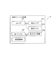
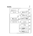
- the substrate working system 1 includes a substrate working device 12 and an appearance inspection device 13.
- the substrate working device 12 is a device for mounting and joining components on a substrate, for example.
- the substrate working system 1 has a plurality of substrate working devices 12 (seven units).
- the appearance inspection apparatus 13 is an apparatus that inspects the mounting state or the bonding state of a component mounted or bonded to a substrate.
- the substrate working system 1 has a plurality of appearance inspection apparatuses 13 (two units).
- a loader 2 a substrate cleaning device 15, a printing machine 3, a printing inspection machine 4, a component mounting device 5, a reflow furnace 6 and an unloader 7 shown in FIG. 1 are examples of the substrate working device 12.
- the board working system 1 may include two or more component mounting apparatuses 5 as the board working apparatus 12. Further, the board working system 1 may include two or more board working apparatuses 12 other than the component mounting apparatus 5. Further, in the substrate working system 1, the substrate inspection device 4 may not be provided as the substrate working device 12, and the substrate cleaning device 15 may not be provided as the substrate working device 12.
- substrate work system 1 is not limited to the system provided with the above-mentioned structure.
- the loader 2 carries the substrate into the substrate working system 1.
- the printing machine 3 prints a wiring pattern on the supplied substrate.
- the print inspection machine 4 inspects the wiring pattern printed on the substrate.
- the component mounting apparatus 5 mounts components on a board.
- the reflow furnace 6 joins the component to the substrate by melting and solidifying the wiring pattern printed on the substrate.
- the unloader 7 carries out the board to which the components are joined from the board working system 1.
- the direction in which the substrate is transported by the conveyor 14 is defined as a substrate transport direction.
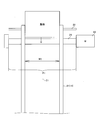
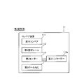
- the loader 2 includes a first conveyor 21, a first motor 23, a first ball screw 24, a first fixed rail 22, and a first encoder 23a.
- the loader 2 has a substrate supply device 25. Note that the configuration of the loader 2 is not limited to the configuration described above, but is merely an example of the configuration of the loader 2.
- the substrate supply device 25 includes a first storage unit and a first transfer unit.
- the first accommodating portion is a rack that accommodates a large number of substrates to be supplied into the substrate working system 1.
- the first transport unit transports the substrate stored in the first storage unit to the supply position on the first conveyor 21.
- the first conveyor 21 extends long in the substrate transfer direction.
- the first conveyor 21 can adjust the interval W1 in the direction orthogonal to the substrate transport direction in the horizontal plane in accordance with the width of the substrate.
- the first ball screw 24 extends long in a direction perpendicular to the substrate transport direction in a horizontal plane.
- the first ball screw 24 is attached to the first motor 23.
- the first ball screw 24 has a central axis that is perpendicular to the substrate transport direction.
- the first ball screw 24 rotates around a direction orthogonal to the substrate transport direction.
- the first fixed rail 22 extends in a direction orthogonal to the substrate transport direction.
- the 1st conveyor 21 is supported by the 1st fixed rail 22 so that a movement in the direction orthogonal to a conveyance direction is possible.
- the first motor 23 is provided with a first encoder 23a that detects rotation.
- the first conveyor 21 moves along the first fixed rail 22 in the length range P ⁇ b> 1 of the first ball screw 24.
- the first encoder 23a can detect the speed C1 of the first conveyor 21 and the position C1 in the direction orthogonal to the substrate transport direction.
- the substrate cleaning device 15 includes a conveyor 151, a first table 152, and a substrate cleaning unit 153. Note that the configuration of the substrate cleaning device 15 is not limited to the configuration described above, but is merely an example of the configuration of the substrate cleaning device 15.
- the conveyor 151 includes a second conveyor 151 a that carries a substrate into the first table 152 and a third conveyor 151 b that carries the substrate out of the third table 42.
- the conveyor 151 has the same configuration as the first conveyor 21.
- the second conveyor 151a and the third conveyor 151b extend long in the substrate transport direction.
- the first table 152 includes a first clamping device 152a that fixes the substrate.
- the substrate cleaning unit 153 is configured to remove foreign matters such as dust on the substrate and remove dirt on the substrate.
- the substrate cleaning unit 153 is an air nozzle.
- the substrate cleaning unit 153 may be a brush unit, a roller, a cleaning sheet, or the like instead of an air nozzle, and the air nozzle is just an example of the substrate cleaning unit 153.
- the second conveyor 151 a transports the substrate carried into the substrate cleaning device 15 by the first conveyor 21 to the first table 152.
- the 1st table 152 supports the board
- the first clamp device 152 a fixes the substrate supported by the first table 152.
- the substrate cleaning unit 153 ejects compressed air from the air nozzle to remove dust and dirt on the substrate. Then, the third conveyor 151 b carries out the substrate from the first table 152.
- the printing machine 3 includes a conveyor 31, a printing stage 32, a squeegee unit 33, and a solder supply unit 34.
- the conveyor 31 includes a fourth conveyor 31a that conveys the substrate to the printing stage 32 and a fifth conveyor 31b that carries out the substrate.
- the conveyor 31 extends long in the substrate transport direction.
- the conveyor 31 has the same configuration as the first conveyor 21.
- the printing stage 32 includes a second table 32a, a second clamping device 32b, a first imaging unit 32d, and a first illumination unit 32e. Further, the printing stage 32 has a mask sheet 32c on which printing openings of a predetermined pattern are formed.
- the first imaging unit 32d is, for example, a CCD camera.
- the first lighting unit 32e is, for example, an LED.
- the other imaging units and illumination units described below have the same configuration.
- the fourth conveyor 31a conveys the substrate carried into the printing machine 3 by the third conveyor 151b to the second table 32a.
- the 2nd table 32a supports the board
- the second clamp device 32b fixes the substrate supported by the second table 32a.
- the solder supply unit 34 supplies paste such as cream solder and conductive paste onto the mask sheet 32c.
- the squeegee unit 33 expands the paste supplied on the mask sheet 32c while kneading on the mask sheet 32c.
- the first imaging unit 32d images the substrate and the mask sheet 32c irradiated with light by the first illumination unit 32e.
- the 5th conveyor 31b carries out a board
- the print inspection machine 4 includes a conveyor 41, a third table 42, a second imaging unit 43, and a second illumination unit 44.
- the configuration of the print inspection machine 4 is not limited to the above-described configuration, but is merely an example of the configuration of the print inspection machine 4.
- the conveyor 41 includes a sixth conveyor 41 a that carries substrates into the third table 42 and a seventh conveyor 41 b that carries substrates from the third table 42.
- the conveyor 41 has the same configuration as the first conveyor 21.
- the sixth conveyor 41a and the seventh conveyor 41b extend long in the substrate transport direction.
- the third table 42 includes a third clamping device 42a that fixes the substrate.
- the sixth conveyor 41a conveys the substrate carried into the printing inspection machine 4 by the fifth conveyor 31b to the third table 42.
- the 3rd table 42 supports the board
- the third clamping device 42 a fixes the substrate supported by the third table 42.
- the second illumination unit 44 irradiates the substrate fixed on the third table 42 with illumination.
- the second imaging unit 43 images the wiring pattern of the substrate illuminated by the second illumination unit 44 in order to confirm the wiring pattern on the substrate.
- the seventh conveyor 41 b carries out the substrate from the third table 42.
- the component mounting apparatus 5 includes a conveyor 51, a fourth table 52, and a component mounting head 53.
- the conveyor 51 includes an eighth conveyor 51 a that carries substrates into the fourth table 52, and a ninth conveyor 51 b that carries substrates from the fourth table 52.
- the conveyor 51 has the same configuration as the first conveyor 21.
- the fourth table 52 includes a fourth clamp device 52a, a camera device 52b, and an illumination device 52c.
- the component mounting head 53 includes a nozzle 53 a that sucks and mounts the component, and a moving mechanism 53 b that moves the component mounting head 53.
- the component mounting head 53 includes a third imaging unit 53c and a third illumination unit 53d.
- the component mounting apparatus 5 includes a component supply unit 54.
- the component supply unit 54 is disposed outside the conveyor 51.
- a plurality of tape feeders 54 a are arranged in the component supply unit 54.
- the tape feeder 54a holds a reel 54b around which a tape holding a plurality of components at a predetermined interval is wound.
- the 8th conveyor 51a conveys the board
- the fourth table 52 supports the substrate carried in from the eighth conveyor 51a from below.
- the fourth clamp device 52 a fixes the substrate supported by the fourth table 52.
- the component mounting head 53 is moved between the component supply unit 54 and the substrate by the moving mechanism 53b.
- the component mounting head 53 sucks the component by the nozzle 53 a in the component supply unit 54.
- the illumination device 52c irradiates light to the nozzle 53a.
- the camera device 52b images the nozzle 53a and the parts adsorbed by the nozzle 53a.
- the camera device 52b performs imaging to confirm the shape of the nozzle 53a and the state of the parts.
- the third illumination unit 53d illuminates the substrate.
- the third imaging unit 53c images the substrate that is illuminated by the third illumination unit 53d.
- the third image pickup unit 53c picks up a fiducial mark (FI (Fiducial Mark) mark) on the substrate and confirms the positional deviation of the substrate.
- FI mark is a mark provided on the substrate in order to align the substrate and the component mounting device 5 before the component mounting device 5 mounts the component on the substrate.
- the component mounting head 53 mounts components on the board.
- the ninth conveyor 51b carries out the board on which the components are mounted from the fourth table 52.
- the reflow furnace 6 includes a conveyor 61, a fifth table 62, a heater 63, and a cooling fan 64.
- the conveyor 61 includes a tenth conveyor 61 a that carries substrates into the fifth table 62 and an eleventh conveyor 61 b that carries substrates from the fifth table 62.
- the conveyor 61 has the same configuration as the first conveyor 21.
- the fifth table 62 has a fifth clamping device 62a.
- the reflow furnace 6 is supplied with oxygen, nitrogen, hydrogen, and formic acid having predetermined concentrations.
- 10th conveyor 61a conveys the board
- FIG. The fifth table 62 supports the substrate conveyed from the tenth conveyor 61a from below.
- the fifth clamp device 62 a fixes the substrate supported by the fifth table 62.
- the heater 63 melts the solder on the board, and the cooling fan 64 cools and hardens the melted solder, so that the component and the board are joined by the solder.
- the 11th conveyor 61b carries out the board
- the unloader 7 includes a twelfth conveyor 71, a second motor 73, a second ball screw 74, a second fixed rail 72, and a second encoder 73a. Further, the unloader 7 has a substrate housing device 75. Note that the configuration of the unloader 7 is not limited to the configuration described above, and is merely an example of the configuration of the unloader 7.
- the twelfth conveyor 71 has the same configuration as the first conveyor 21.
- the twelfth conveyor 71 extends long in the substrate transport direction. In the twelfth conveyor 71, the interval in the direction orthogonal to the substrate transport direction can be adjusted according to the width of the substrate.
- the second ball screw 74 extends long in a direction orthogonal to the substrate transport direction.
- the second ball screw 74 is attached to the second motor 73.
- the second ball screw 74 has a central axis that is perpendicular to the substrate transport direction.
- the second ball screw 74 rotates around a direction orthogonal to the substrate transport direction.
- the second fixed rail 72 extends in a direction orthogonal to the substrate transport direction.
- the 12th conveyor 71 is supported by the 2nd fixed rail 72 so that a movement in the direction orthogonal to a conveyance direction is possible.
- the second motor 73 is provided with a second encoder 73a that detects rotation.
- the substrate storage device 75 includes a second storage part 75a and a second transport part 75b.
- the 2nd conveyance part 75b carries in the board
- the second accommodating portion 75a is a rack that accommodates a large number of substrates to which components are joined by solder.
- the loader 2 can detect the speed of the twelfth conveyor 71 and the position in the direction orthogonal to the substrate transport direction by the second encoder 73a.
- the substrate working system 1 includes a first appearance inspection device 8 and a second appearance inspection device 9.
- the first appearance inspection device 8 or the second appearance inspection device 9 may be used as the appearance inspection device.
- substrate work system 1 is not limited to the system provided with the above-mentioned structure.
- the first appearance inspection device 8 is disposed on the upstream side of the reflow furnace 6.
- the first appearance inspection device 8 inspects the components on the board, the solder on the board, and the board before being carried into the reflow furnace 6.
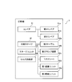
- the first appearance inspection device 8 includes a conveyor 81, a sixth table 82, a first inspection head 83, and a first measuring device 84.
- the configuration of the first appearance inspection apparatus 8 is not limited to the above-described configuration, but is merely an example of the configuration of the first appearance inspection apparatus 8.
- the conveyor 81 has a thirteenth conveyor 81 a disposed on the upstream side of the sixth table 82 and a fourteenth conveyor 81 b disposed on the downstream side of the sixth table 82.
- the conveyor 81 has the same configuration as the first conveyor 21.
- the thirteenth conveyor 81 a carries the substrate into the sixth table 82.
- the fourteenth conveyor 81 b carries out the substrate from the sixth table 82.
- the sixth table 82 has a sixth clamping device 82a.
- the first inspection head 83 includes a fourth imaging unit 83a and a fourth illumination unit 83b.
- the first measuring device 84 has a first height measuring device 84a.
- the first height measuring device 84a there are a laser measuring device using laser light, a 3D measuring device using moire light emitted from a projector, and the like. Note that the measurement devices listed as the first height measurement device 84a are merely examples.
- the thirteenth conveyor 81a conveys the substrate carried into the first appearance inspection apparatus 8 by the ninth conveyor 51b to the sixth table 82.
- the sixth table 82 supports the substrate carried in from the thirteenth conveyor 81a from below.
- the sixth clamp device 82 a fixes the substrate supported by the sixth table 82.
- the fourth illumination unit 83b illuminates the substrate.
- the fourth imaging unit 83a images the components on the board, the solder on the board, and the board.
- the first height measuring device 84a measures the solder height of the solder at the joint between the substrate and the component.
- the fourteenth conveyor 81b carries out the substrate from the sixth table 82.
- the first appearance inspection apparatus 8 images the substrate by the fourth imaging unit 83a, thereby allowing the positional deviation of the substrate, the foreign matter on the substrate, the arrangement of the components, the missing components, and the like before the reflow process. Inspection of solder misalignment, component misalignment, component height, component lead height, etc. Further, the first appearance inspection apparatus 8 measures the solder height, area, and volume by measuring the solder at the joint portion between the substrate and the component before the reflow process by the first height measuring device 84a. . Further, the first appearance inspection device 8 may measure the component height, the lead height of the component, and the like by measuring the component before the reflow process by the first height measuring device 84a.
- the second appearance inspection device 9 is disposed downstream of the reflow furnace 6 (see FIG. 1).
- the second appearance inspection device 9 inspects the components on the board, the solder on the board, and the board after being removed from the reflow furnace 6.
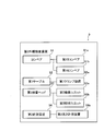
- the second appearance inspection device 9 includes a conveyor 91, a seventh table 92, a second inspection head 93, and a second measuring device 94.
- the configuration of the second appearance inspection apparatus 9 is not limited to the configuration described above, but is merely an example of the configuration of the second appearance inspection apparatus 9.
- the conveyor 91 has a fifteenth conveyor 91 a disposed on the upstream side of the seventh table 92 and a sixteenth conveyor 91 b disposed on the downstream side of the seventh table 92.
- the conveyor 91 has the same configuration as the first conveyor 21.
- the fifteenth conveyor 91 a carries the substrate onto the seventh table 92.
- the sixteenth conveyor 91 b carries out the substrate from the seventh table 92.
- the seventh table 92 has a seventh clamping device 92a.
- the second inspection head 93 has a fifth imaging unit 93a and a fifth illumination unit 93b.
- the second measuring device 94 has a second height measuring device 94a.
- the 15th conveyor 91a conveys the board
- FIG. The seventh table 92 supports the substrate carried in from the sixteenth conveyor 91b from below.
- the seventh clamp device 92 a fixes the substrate supported by the seventh table 92.
- the fifth illumination unit 93b illuminates the substrate.
- the fifth imaging unit 93a images the components on the board, the solder on the board, and the board.
- the second height measuring device 94a measures the solder height of the solder at the joint between the substrate and the component.
- the sixteenth conveyor 91b carries out the substrate from the seventh table 92.
- the second appearance inspection apparatus 9 images the substrate by the fifth imaging unit 93a, so that the positional deviation of the substrate, the foreign matter on the substrate, the arrangement of the component, the missing component, and the like after the reflow process. Inspection of solder misalignment, component misalignment, component height, component lead height, etc. Moreover, the 2nd external appearance inspection apparatus 9 measures the height, area, and volume of a solder after a reflow process by measuring the junction part of a board
- the board working system 1 includes the board working apparatus 12 including at least the component mounting apparatus 5 for mounting components on the board.
- the board working system 1 also includes an appearance inspection apparatus 13 that inspects the mounting state of components on the board by the component mounting apparatus 5.
- the appearance inspection apparatus 13 includes a first appearance inspection apparatus 8 and a second appearance inspection apparatus 9 disposed downstream from the first appearance inspection apparatus 8.
- a reflow furnace 6 is disposed between the first appearance inspection device 8 and the second appearance inspection device 9.
- the calibration In the substrate working system 1 of the present embodiment, calibration for returning the substrate working apparatus 12 to the initial state is performed on the defective portion of the substrate working apparatus 12.
- the calibration means returning to the original state in which each of the substrate working apparatuses 12 is installed. Note that calibration is defined as including returning to the previous calibration state.
- the first visual inspection apparatus 8 and the second visual inspection apparatus 9 perform an inspection process on the substrate, the components on the substrate, and the solder on the substrate. Hereinafter, the inspection process will be described.
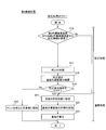
- the first visual inspection device 8 or the second visual inspection device 9 specifies the defective substrate working device 12 and the defective portion based on the inspection processing as shown in FIG. In the following, based on FIG. 12, as an example, the specification of the substrate working device 12 that is defective by the first appearance inspection device 8 and the specification of the defective portion will be described.
- step S1 the substrate is inspected by the first appearance inspection device 8.
- the first appearance inspection device 8 inspects the substrate on which the wiring pattern is printed by the printing machine 3 and the component is mounted by the component mounting device 5.
- the inspection by the first appearance inspection apparatus 8 includes, for example, inspection such as missing parts on the substrate, solder area, width and height of the entire substrate, presence / absence of foreign matter on the substrate, and whether or not the FI mark can be imaged. There is.
- the above-described inspection is performed by appropriately using, for example, a measurement device such as the fourth imaging unit 83a and the first height measurement device 84a. Thereafter, the process proceeds to step S2.
- step S2 the first appearance inspection apparatus 8 determines whether or not the defective portion needs to be calibrated based on the inspection item diagnosed as defective by the inspection in step S1.
- the first appearance inspection device 8 inspects whether or not the number of times of diagnosis as defective is equal to or greater than a threshold value.
- the inspection process ends.
- the first appearance inspection device 8 determines that the calibration process is to be performed when the number of times diagnosed as defective is equal to or greater than the threshold, and proceeds to step S3. Further, the first appearance inspection apparatus 8 may make the calibration determination based on the increasing rate of the number of times diagnosed as defective per predetermined time.
- the first appearance inspection apparatus 8 ends the inspection process as it is when the rate of increase in the number of times diagnosed as defective per predetermined time is less than a predetermined value.
- the first appearance inspection device 8 determines that calibration is to be performed when the rate of change in the number of times diagnosed as defective per predetermined time is equal to or greater than a predetermined value, and proceeds to step S3.
- step S ⁇ b> 3 the first appearance inspection device 8 specifies the substrate working device 12 associated with the inspection item (for example, the solder area on the substrate and the printing machine 3) based on the inspection item diagnosed as defective. . Thereafter, the process proceeds to step S4. In step S4, the first visual inspection apparatus 8 automatically notifies the substrate working apparatus 12 specified in step S3 of the calibration information including the defective portion and the calibration content to be performed. Then, the process proceeds to step S5. In step S ⁇ b> 5, the first appearance inspection device 8 ends the work after carrying out the substrate.
- the substrate working device 12 for example, the solder area on the substrate and the printing machine 3
- step S6 the substrate working apparatus 12 determines whether calibration information has been received from the first appearance inspection apparatus 8 or the second appearance inspection apparatus 9. If calibration information has been received, the process proceeds to step S7. If calibration information has not been received, the process proceeds to step S13.
- step S7 the substrate working apparatus 12 inspects the specified defective portion based on the calibration information. Thereafter, in step S8, the substrate working apparatus 12 proceeds to step S8 in order to perform calibration processing when the specified defective portion is defective based on the inspection result in step S7. Moreover, in the board
- step S9 the substrate working device 12 automatically calibrates based on the calibration content included in the calibration information notified from the first appearance inspection device 8. Thereafter, in step S10, it is inspected whether or not the defect has been eliminated by the calibration performed by the substrate working apparatus 12. And in the board
- step S12 the substrate working device 12 stops all the substrate working devices 12 of the substrate working system 1, and notifies the operator that the defect detected by the first appearance inspection device 8 has not been eliminated.
- step S11 the substrate working apparatus 12 proceeds to step S13 when the inspection performed in step S10 can be cleared.
- Steps S6 to S12 are calibration processes, and Steps S13 to S15 are normal processes for performing a normal operation of the substrate working apparatus 12 after the calibration process of the substrate working apparatus 12 is completed.
- step S13 the substrate working device 12 carries the substrate into the substrate working device 12 in which the defect has been eliminated, and sets the substrate at a predetermined working position.
- step S ⁇ b> 14 the substrate working apparatus 12 performs a predetermined work operation on the loaded substrate in the substrate working apparatus 12 in which the defect is eliminated.
- step S15 the substrate working device 12 carries out the substrate on which the predetermined work operation has been performed from the substrate working device 12 in which the defect has been eliminated.
- the first appearance inspection device 8 inspects the FI mark as one of inspections by the fourth imaging unit 83a in step S1.
- the first appearance inspection apparatus 8 determines whether or not to calibrate the loader 2 based on the FI mark inspection result in step S2.
- the first appearance inspection apparatus 8 is configured to load the loader 2 when an error that the FI mark is not captured (hereinafter referred to as the first error) occurs five times or more in the image of the substrate captured by the fourth imaging unit 83a. It is determined that calibration will be performed.
- One possible cause of the first error is an error that occurs when the widths of the substrate and the first conveyor 21 do not match.
- the 1st external appearance inspection apparatus 8 can estimate factors other than the width
- step S7 the loader 2 checks the loader 2 for the first error at the current position and width of the first conveyor 21, the position C1 (see FIG. 3) and the width W1 of the first conveyor 21 at the beginning of installation (FIG. 3). Check).
- step S8 the loader 2 determines whether to calibrate the loader 2 based on the inspection result in step S7.
- step S ⁇ b> 9 the loader 2 returns the position in the direction orthogonal to the transport direction of the first conveyor 21 to the initial position of the installation by the first motor 23 as the content of the calibration of the loader 2 with respect to the first error.
- step S9 the loader 2 returns the width in the direction orthogonal to the conveying direction of the first conveyor 21 to the initial value at the time of installation as the content of the calibration of the loader 2 for the first error.
- step S10 the loader 2 compares the position and width of the first conveyor 21 after calibration with the position and width of the first conveyor 21 after installation as an inspection of the content of the calibration of the loader 2 for the first error. To do. As a result, the loader 2 determines whether the content of the calibration is good or bad.
- the threshold for the number of occurrences of the first error is not limited to five.
- the information that the first appearance inspection device 8 determines to calibrate the loader 2 includes, for example, not only the number of occurrences of the first error but also the transition of the occurrence of the first error and the first height measuring device 84a. It may be a measured value or the like.
- the FI mark inspection is given as a specific example of the inspection of the loader 2 of the first appearance inspection device 8, but the inspection of the loader 2 of the first appearance inspection device 8 is not limited to the inspection of the FI mark.
- step S1 the first appearance inspection apparatus 8 inspects the foreign matter or dirt on the substrate as one of inspections by the fourth imaging unit 83a.
- step S2 the first appearance inspection device 8 determines whether or not to calibrate the substrate cleaning device 15 based on the inspection result of the foreign matter or dirt on the substrate.
- the first appearance inspection device 8 detects the substrate cleaning device 15 when an error (hereinafter referred to as a second error) occurs on the substrate in the image of the substrate imaged by the fourth imaging unit 83a. Determine that calibration is to be performed.
- One possible cause of the second error is an error that occurs due to the clogging of the air nozzle of the substrate cleaning unit 153 of the substrate cleaning device 15.
- the first appearance inspection apparatus 8 can estimate factors other than the clogging of the air nozzle as the second error occurrence factor, and can also perform calibration.
- step S7 the substrate cleaning device 15 performs an inspection by comparing the image of the air nozzle by an imaging unit (not shown) with the image of the air nozzle at the time of installation as an inspection of the substrate cleaning device 15 for the second error.
- step S8 the substrate cleaning device 15 determines whether the substrate cleaning device 15 is inspected based on the inspection result in step S7.
- step S ⁇ b> 9 the substrate cleaning device 15 eliminates the clogging of the air nozzle by blowing air to the air nozzle of the substrate cleaning unit 153 as the calibration content of the substrate cleaning device 15 for the second error. At this time, the substrate cleaning device 15 returns the air nozzle to the initial state.
- step S10 the substrate cleaning device 15 compares the image of the air nozzle after calibration by the imaging unit with the image of the air nozzle at the time of installation as an inspection of the calibration content of the substrate cleaning device 15 for the second error. To do. As a result, the substrate cleaning device 15 determines whether the content of the calibration is acceptable.
- the information that the first appearance inspection device 8 determines to calibrate the substrate cleaning device 15 may be, for example, not only foreign matter or dirt on the substrate but also floating components on the substrate. Further, as an inspection of the substrate cleaning device 15 of the first appearance inspection apparatus 8, the foreign matter or dirt on the substrate is given as a specific example, but the inspection of the substrate inspection device 15 of the first appearance inspection device 8 is a foreign matter on the substrate. Or it is not limited to the inspection of dirt. The inspection of the first appearance inspection device 8 for the substrate cleaning device 15 may be a foreign matter on the substrate or a floating component on the substrate. Further, the first appearance inspection apparatus 8 may detect the occurrence of the second error based on the height, width, and volume of the solder by the first height measuring device 84a.
- the calibration of the substrate cleaning device 15 may be performed not only by air blow but also by cleaning the air nozzle, replacing the air nozzle, adjusting the air pressure of the air nozzle, and adjusting the jet angle of the air nozzle.
- the substrate cleaning device 15 is a brush unit, a roller, and a cleaning sheet
- the calibration of the substrate cleaning device 15 may be performed by cleaning and replacing the brush unit, the roller, and the cleaning sheet.
- the first appearance inspection apparatus 8 inspects the solder application area on the substrate as one of inspections by the fourth imaging unit 83a in step S1.
- the first appearance inspection apparatus 8 determines whether or not to calibrate the printing machine 3 based on the inspection result of the solder application area in step S2. In other words, the first appearance inspection apparatus 8 determines that the printing machine has an error that the solder application area is less than a predetermined area (hereinafter referred to as a third error) five times or more in the image of the board imaged by the fourth imaging unit 83a. It is determined that the calibration of 3 is performed.
- One possible cause of the third error is an error that occurs due to clogging of the mask sheet 32c.
- the first appearance inspection apparatus 8 can estimate factors other than the clogging of the mask sheet 32c as the third error occurrence factor, and can also perform calibration.
- the printing machine 3 compares the image of the current mask sheet 32c imaged by the first imaging unit 32d with the image of the mask sheet 32c at the beginning of installation as an inspection of the printing machine 3 for the third error in step S7. Perform an inspection.
- the printing machine 3 determines whether to calibrate the printing machine 3 based on the inspection result in step S7.
- the printing machine 3 eliminates clogging of the mask sheet 32 c by blowing compressed air on the mask sheet 32 c using an air blower (not shown) as the calibration contents of the printing machine 3 for the second error. Then, the mask sheet 32c is returned to the initial state.
- step S10 the printing machine 3 checks the contents of the calibration of the printing machine 3 against the second error, the image of the calibrated mask sheet 32c imaged by the first imaging unit 32d, and the initial mask sheet 32c. Compare the image with. As a result, the printing press 3 determines whether the content of the calibration is acceptable.
- the first appearance inspection apparatus 8 may detect the occurrence of the third error based on the height, width and volume of the solder by the first height measuring device 84a. Further, as the content of the calibration of the printing machine 3 with respect to the third error, alignment between the land of the substrate and the mask hole of the mask sheet 32c may be performed. Further, as the content of the calibration of the printing machine 3 with respect to the third error, the pressing pressure and pressing time of the squeegee unit 33 may be adjusted, and the attack angle and speed may be adjusted.
- the threshold for the number of occurrences of the third error is not limited to five.
- the information that the first appearance inspection device 8 determines to calibrate the printing machine 3 may be, for example, not only the solder application area but also the solder volume, the solder position shift, and the solder blur. Further, as an inspection of the first appearance inspection apparatus 8 with respect to the printing machine 3, the solder application area on the substrate is given as a specific example. However, the inspection of the first appearance inspection apparatus 8 with respect to the printing machine 3 includes solder volume, solder Misalignment of solder and fading of solder. Further, in the first appearance inspection apparatus 8, even if the occurrence of the third error is detected based on the solder height, width, and volume by the first height measuring device 84a (laser measuring device, 3D measuring device, etc.). Good.
- the first appearance inspection apparatus 8 inspects the solder application area on the substrate as one of inspections by the fourth imaging unit 83a in step S1. In step S2, the first appearance inspection apparatus 8 determines whether or not to calibrate the print inspection machine 4 based on the inspection result of the solder application area. That is, the first appearance inspection device 8 performs a print inspection when an error that the solder application area is less than a predetermined area (hereinafter referred to as a fourth error) occurs five times or more in the image of the board imaged by the fourth imaging unit 83a. It is determined that the machine 4 is to be calibrated.
- a predetermined area hereinafter referred to as a fourth error
- One possible cause of the fourth error is an error that occurs due to a decrease in image quality of the third imaging unit 53c due to insufficient light quantity of the third illumination unit 53d of the printing inspection machine 4.
- the first appearance inspection apparatus 8 can estimate factors other than the insufficient light amount of the third illumination unit 53d of the printing inspection machine 4 as the fifth error occurrence factor, and can also perform calibration.
- the printing inspection machine 4 performs the illuminance inspection of the fourth illumination unit 83b as the inspection of the printing inspection machine 4 for the fourth error in step S7.
- the illuminance inspection is performed using a luminance meter (not shown).
- the printing inspection machine 4 performs inspection by comparing the measured values of the luminance meters of the illuminance of the fourth illumination unit 83b and the illuminance of the fourth illumination unit 83b at the beginning of installation.
- step S8 the print inspection machine 4 determines whether to calibrate the print inspection machine 4 based on the inspection result in step S7.
- step S9 the print inspection machine 4 adjusts the illuminance of the third illumination unit 53d as the calibration content of the print inspection machine 4 for the fourth error, thereby eliminating the illuminance shortage of the third illumination unit 53d.
- the printing inspection machine 4 returns the third illumination unit 53d to the initial state.
- step S10 the print inspection machine 4 checks the current illuminance of the fourth illumination unit 83b and the illuminance of the fourth illumination unit 83b at the beginning of installation as an inspection of the contents of the calibration of the print inspection machine 4 for the third error. Compare Thereby, the printing inspection machine 4 determines whether the content of the calibration is acceptable.
- the threshold for the number of occurrences of the fourth error is not limited to five.
- the information that the first appearance inspection device 8 determines to calibrate the printing inspection machine 4 may be, for example, not only the solder application area but also the solder volume, solder position deviation, and solder blur. .
- the solder application area on the substrate is given as a specific example. And solder misalignment and solder fading. Further, in the first appearance inspection apparatus 8, even if the occurrence of the third error is detected based on the solder height, width, and volume by the first height measuring device 84a (laser measuring device, 3D measuring device, etc.). Good.
- step S1 the first appearance inspection apparatus 8 inspects a missing part of a component on the board as one of inspections by the fourth imaging unit 83a.
- the first appearance inspection device 8 determines whether or not to calibrate the component mounting device 5 based on the inspection result of the missing component on the board in step S2.
- the first appearance inspection apparatus 8 detects that a component missing part (hereinafter, “fifth error”) placed at a predetermined position in the image of the board imaged by the fourth imaging unit 83a occurs. It is determined that calibration will be performed.
- a component missing part hereinafter, “fifth error”
- One possible cause of the fifth error is an error that occurs due to damage to the nozzle 53a of the component mounting apparatus 5.
- the first appearance inspection apparatus 8 can estimate factors other than the damage of the nozzle 53a of the component mounting apparatus 5 as the fifth error occurrence factor, and can also perform calibration.
- step S7 the component mounting apparatus 5 performs an inspection by comparing the image of the nozzle 53a by the fourth imaging unit 83a with the image of the nozzle 53a at the beginning of installation as an inspection of the component mounting apparatus 5 for the fourth error. .
- step S8 the component mounting apparatus 5 determines whether the component mounting apparatus 5 is inspected based on the inspection result in step S7.
- step S9 the component mounting apparatus 5 eliminates the damage to the nozzle 53a by replacing the nozzle 53a of the component mounting head 53 as the calibration content of the component mounting apparatus 5 for the fourth error. At this time, the component mounting apparatus 5 returns the nozzle 53a to the initial state.
- step S10 the component mounting apparatus 5 then inspects the contents of calibration of the component mounting apparatus 5 for the fourth error, and the image of the nozzle 53a after calibration by the fourth imaging unit 83a and the image of the nozzle 53a at the beginning of installation. And compare. Thereby, the component mounting apparatus 5 determines the quality of the content of calibration.
- the component mounting apparatus 5 determines the quality of the content of calibration.
- the first appearance inspection device 8 and the second appearance inspection device 9 provide the above-described plurality of generation factors for one error on the substrate discovered by inspection. Can be estimated. Furthermore, in the substrate working system 1, the substrate working apparatus 12 corresponding to each of the plurality of occurrence factors can perform calibration related to each of the plurality of occurrence factors.
- the component mounting apparatus 5 may inspect the vacuum pressure of the nozzle 53a as an inspection of the calibration content of the component mounting apparatus 5 for the fourth error.
- the first appearance inspection apparatus 8 performs component mounting based on the floating of the component on the substrate, the positional deviation, the reversal of the component, and the reversal of the component polarity as one of the inspections by the fourth imaging unit 83a in step S2. It may be determined whether or not the device 5 is calibrated. That is, when the first appearance inspection apparatus 8 is in a state in which the component is lifted and displaced from a predetermined state in the image of the board imaged by the fourth imaging unit 83a (hereinafter referred to as a sixth error), the component It is determined that the mounting apparatus 5 is to be calibrated. As one of the causes of the sixth error, an error that occurs when the nozzle 53a of the component mounting apparatus 5 is damaged can be considered. Note that the first appearance inspection apparatus 8 can estimate factors other than the damage of the nozzle 53a of the component mounting apparatus 5 as the cause of the sixth error, and can also perform calibration.
- the deformation of the nozzle 53a is eliminated by replacing the nozzle 53a of the component mounting head 53 in step S9. At this time.
- the component mounting apparatus 5 returns the nozzle 53a to the initial state.
- the component mounting apparatus 5 then inspects the contents of calibration of the component mounting apparatus 5 for the sixth error, and the image of the nozzle 53a after calibration by the fourth imaging unit 83a and the image of the nozzle 53a at the beginning of installation. And compare. Thereby, the component mounting apparatus 5 determines the quality of the content of calibration.
- the first appearance inspection apparatus 8 determines the component mounting apparatus 5 based on the imaging result by the fourth imaging unit 83a or the measurement result of the first height measuring apparatus 84a of the foreign matter attached to the component on the board. It may be determined whether or not to calibrate. In other words, the first appearance inspection device 8 calibrates the component mounting device 5 when a foreign object is attached to the component in the image of the board imaged by the fourth imaging unit 83a (hereinafter referred to as a seventh error). Judge to do. One possible cause of the seventh error is an error that occurs due to foreign matter adhering to the nozzle 53a of the component mounting apparatus 5. The first appearance inspection device 8 can estimate factors other than the adhering of foreign matter to the nozzle 53a of the component mounting device 5 as the seventh error generation factor, and can also perform calibration.
- the component mounting apparatus 5 eliminates the contamination of the nozzle 53a by replacing the nozzle 53a of the component mounting head 53 in step S9. At this time, in the component mounting apparatus 5, the nozzle 53a returns to the initial state.
- step S10 in the component mounting apparatus 5, as an inspection of the content of the calibration of the component mounting apparatus 5 for the seventh error, the image of the nozzle 53a after the calibration by the fourth imaging unit 83a and the image of the nozzle 53a at the beginning of installation. And compare. Thereby, the component mounting apparatus 5 determines the quality of the content of calibration.
- the first appearance inspection apparatus 8 determines whether or not to calibrate the component mounting apparatus 5 based on the inspection result of the front / back inversion or front / reverse inversion of the component on the board by the fourth imaging unit 83a in step S2. Also good. In other words, the first appearance inspection device 8 determines that the component mounting device 5 is in a state where the component is reversed from front to back or front and back reversed (hereinafter, “8th error”) in the image of the board imaged by the fourth imaging unit 83a. Determine that calibration is to be performed.
- One of the causes of the eighth error may be an error that occurs due to a shift in the component supply position, a shift in feed time, or a shift in feed speed in the tape feeder 54a of the component mounting apparatus 5.
- step S9 the component mounting apparatus 5 automatically adjusts the component feed position of the tape feeder 54a, thereby reversing the front and back of the component or reversing the front and back. Eliminate.
- the tape feeder 54a returns to the initial state.
- step S10 the component mounting apparatus 5 sets the current value of the calibrated reel 54b that moves the tape feeder 54a and the installation as an inspection of the calibration content of the component mounting apparatus 5 for the eighth error. The initial current value of the reel 54b is compared. Thereby, the component mounting apparatus 5 determines the quality of the content of calibration.
- step S1 the second appearance inspection apparatus 9 inspects the substrate on which the wiring pattern is printed by the printing machine 3 and the component is bonded to the substrate by the reflow furnace 6.
- inspections by the second appearance inspection apparatus 9 there is an inspection using an image of a substrate imaged by the fourth imaging unit 83a.
- inspections using images include inspections such as missing parts on the board, solder area of the entire board, presence or absence of foreign matter on the board, whether or not a fiducial mark (hereinafter referred to as FI mark) can be imaged. .
- FI mark fiducial mark
- the inspection using the second height measuring device 94a includes inspection such as solder width and height. Thereafter, the process proceeds to step S2.
- the substrate working apparatus 12 in which the calibration process is performed based on the inspection by the second appearance inspection apparatus 9 in the substrate working apparatus 12 other than the substrate working apparatus 12 described in the calibration process of the first appearance inspection apparatus 8 will be described.
- step S1 the second appearance inspection apparatus 9 inspects the solder volume applied on the substrate as one of inspections by the fifth imaging unit 93a.
- the second appearance inspection apparatus 9 determines whether or not to calibrate the reflow furnace 6 based on the inspection result of the solder volume on the substrate in step S2. That is, the second appearance inspection device 9 calibrates the reflow furnace 6 when the solder volume at the time of the current inspection is reduced by about 10% or more from the solder volume on the substrate at the time of the first inspection (hereinafter referred to as the ninth error).
- the ninth error may be an error that occurs due to a change in the concentration or ratio of oxygen, nitrogen, hydrogen, and formic acid charged in the reflow furnace 6.
- the second appearance inspection device 9 can estimate factors other than changes in the concentration or ratio of oxygen, nitrogen, hydrogen and formic acid charged in the reflow furnace 6 as the ninth error generation factor, Calibration can also be performed.
- step S7 the reflow furnace 6 checks the current oxygen, nitrogen, hydrogen and formic acid concentrations as well as the initial oxygen, nitrogen, hydrogen and formic acid concentrations as an inspection of the reflow furnace 6 for the ninth error by a concentration meter (not shown). Compare the concentration.
- step S8 the reflow furnace 6 determines whether or not the reflow furnace 6 is calibrated based on the inspection result in step S7.
- step S9 the reflow furnace 6 eliminates the decrease in the solder volume by supplying oxygen, nitrogen, hydrogen and formic acid into the reflow furnace 6 as the contents of calibration of the reflow furnace 6 for the ninth error.
- the reflow furnace 6 returns the concentrations of oxygen, nitrogen, hydrogen and formic acid in the reflow furnace 6 to the initial state. Then, in step S10, the reflow furnace 6 inspects the contents of the calibration of the reflow furnace 6 for the ninth error, the concentration of oxygen, nitrogen, hydrogen and formic acid after calibration, and the initial oxygen, nitrogen, hydrogen and formic acid after installation. Compare the concentration of Thereby, the reflow furnace 6 judges the quality of the content of calibration.
- blow by an air blow device (not shown) in the reflow furnace 6 may be performed. Further, in the reflow furnace 6, the temperature of the heater 63 of the reflow furnace 6 may be adjusted as the content of calibration of the reflow furnace 6 with respect to the ninth error.
- the information that the second visual inspection apparatus 9 determines to calibrate the reflow furnace 6 may not be the volume of solder applied on the substrate.
- the solder volume applied on the substrate is given as a specific example.
- the inspection of the reflow furnace 6 of the second appearance inspection apparatus 9 is applied on the substrate. It is not limited to the inspection of the solder volume.
- the second appearance inspection apparatus 9 may detect the occurrence of the ninth error based on the height, width and volume of the solder by the second height measuring apparatus 94a.
- the FI mark is inspected as one of inspections by the fifth imaging unit 93a in step S1.
- the unloader 7 performs the same calibration as that of the loader 2 on the basis of the FI mark inspection result in step S2.
- the second appearance inspection device 9 determines that the loader 2 is not loaded when an error that the FI mark is not captured (hereinafter referred to as the tenth error) occurs five times or more in the image of the substrate captured by the fifth imaging unit 93a. It is determined that the unloader 7 is to be calibrated in the same manner.
- the unloader 7 inspects the current position and width of the twelfth conveyor 71 and the position and width of the twelfth conveyor 71 at the beginning of installation as the inspection of the unloader 7 for the tenth error in step S7.
- the unloader 7 determines whether to calibrate the unloader 7 based on the inspection result in step S7.
- step S ⁇ b> 9 the unloader 7 returns the position in the direction orthogonal to the transport direction of the twelfth conveyor 71 to the initial position of the installation by the second motor 73 as the calibration contents of the unloader 7 for the tenth error.
- step S9 the unloader 7 returns the width in the direction perpendicular to the transport direction of the twelfth conveyor 71 to the initial value at the time of installation as the calibration contents of the unloader 7 for the tenth error.
- step S10 the unloader 7 checks the position and width of the twelfth conveyor 71 after calibration, and the position and width of the twelfth conveyor 71 at the beginning of installation as an inspection of the calibration contents of the unloader 7 for the tenth error. Compare As a result, the unloader 7 determines whether the content of the calibration is acceptable.
- the threshold for the number of occurrences of the tenth error is not limited to five.
- the information that the second appearance inspection device 9 determines to calibrate the unloader 7 includes, for example, not only the number of occurrences of the tenth error but also the transition of the occurrence of the tenth error and the second height measuring device 94a. May be a measured value.
- the FI mark inspection is given as a specific example of the inspection of the unloader 7 of the second appearance inspection device 9, but the inspection of the unloader 7 of the second appearance inspection device 9 is not limited to the inspection of the FI mark.
- the substrate working system 1 is configured to perform calibration for returning the substrate working device 12 to the initial state based on the inspection result of the appearance inspection device 13.
- the substrate working system 1 performs calibration to return the mechanical components (for example, the width and position of the conveyor 31) of the substrate working apparatus 12 to the initial state based on the inspection result of the appearance inspection apparatus 13. It is configured.
- the substrate working system 1 is configured to specify the substrate working device 12 to be configured based on the inspection result of the appearance inspection device 13. Further, the substrate working system 1 is configured to notify calibration information for performing calibration for returning the specified substrate working apparatus 12 to the initial state.
- the calibration information includes information on a defective portion of the board working device 12 specified by the inspection result of the appearance inspection device 13 (for example, deformation of the nozzle 53a of the component mounting device 5).
- the substrate working device 12 is configured to perform calibration based on the information on the defective part.
- the substrate working device 12 is configured to inspect a defective portion to be calibrated based on the notified calibration information and determine whether or not calibration is necessary based on the inspection result of the defective portion.
- the substrate working device 12 is configured to perform the configuration when it is determined that calibration is necessary.
- the substrate working device 12 is configured to inspect the defective part after calibration again and perform the operation on the substrate when the inspection passes.
- the board working system 1 includes a board working apparatus 12 including at least a component mounting apparatus 5 and an appearance inspection apparatus 13.
- the substrate working system 1 calibration for returning the substrate working apparatus 12 to the initial state is performed based on the inspection result of the appearance inspection apparatus 13.
- the degree of mismatch between the calibrated substrate work apparatus 12 and another substrate work apparatus 12 can be reduced.
- the mechanical component of the substrate working apparatus 12 is calibrated so that the substrate working apparatus 12 returns to the initial state.
- the mechanical component of the substrate working apparatus 12 is calibrated so that the substrate working apparatus 12 returns to the initial state.
- the first appearance inspection device 8 and the second appearance inspection device 9 identify the substrate working device 12 having a defective portion based on the respective inspection results. Then, the first appearance inspection apparatus 8 and the second appearance inspection apparatus 9 notify the substrate work apparatus 12 having a defective portion of calibration information for performing calibration for returning the specified substrate work apparatus 12 to the initial state. Thereby, the operator can easily recognize the substrate working apparatus that requires calibration. As a result, it is possible to reduce the amount of work for the operator when the substrate working apparatus 12 is calibrated.
- the calibration information includes information on a defective portion of the substrate working device 12, and the substrate working device 12 performs calibration based on the information on the defective portion.
- the substrate working system 1 can automatically identify the defective portion of the substrate working apparatus 12 that requires calibration based on the inspection results of the first appearance inspection apparatus 8 and the second appearance inspection apparatus 9.
- the calibration can be automatically performed on the substrate working apparatus 12 side based on the information on the defective portion. As a result, the burden on the operator can be reduced.
- the substrate working device 12 inspects a defective portion to be calibrated based on the calibration information, and determines whether calibration is necessary based on the inspection result of the defective portion. Then, the substrate working device 12 performs calibration when it is determined that calibration is necessary. As a result, the substrate work apparatus 12 can reconfirm the necessity of calibration for the result of necessity of calibration of the substrate working apparatus 12 based on the inspection results of the first appearance inspection apparatus 8 and the second appearance inspection apparatus 9. it can. As a result, it is possible to prevent the substrate work apparatus 12 that does not require calibration from being calibrated.
- the substrate working apparatus 12 inspects the defective part after the calibration again, and performs the operation on the substrate when the inspection passes. Thereby, it can be confirmed whether the defect location of the board
- the reflow furnace 6 is disposed between the first appearance inspection device 8 and the second appearance inspection device 9.
- melted by the reflow furnace 6 can be test
- the first appearance inspection device 8 and the second appearance inspection device 9 are used to inspect changes on the substrate before and after the reflow, the defect is more accurately detected than when the inspection is performed with only one appearance inspection device 13.
- the generated substrate working device 12 can be identified.
- the substrate working system 1 according to the first modified example includes a dispenser 10 as the substrate working device 12.
- the substrate working system 1 includes a dispenser 10. As shown in FIG. 14, the dispenser 10 includes a conveyor 101, an eighth table 102, and a head unit 103. Note that the configuration of the dispenser 10 is not limited to the above-described configuration, but is merely an example of the configuration of the dispenser 10.
- the conveyor 101 has a seventeenth conveyor 101 a that carries substrates into the eighth table 102 and an eighteenth conveyor 101 b that carries substrates from the eighth table 102.
- the conveyor 101 has the same configuration as the first conveyor 21.
- the seventeenth conveyor 101a and the eighteenth conveyor 101b extend long in the substrate transport direction.
- the eighth table 102 has an eighth clamping device 102a.
- the head unit 103 includes a syringe 103a that stores an adhesive and the like, and a nozzle 103b that discharges the adhesive and the like in the syringe 103a.
- the head unit 103 includes a sixth imaging unit 103c and a sixth illumination unit 103d.
- the 17th conveyor 101a conveys the substrate to the eighth table 102.
- the eighth table 102 supports the substrate conveyed from the seventeenth conveyor 101a from below.
- the eighth clamp device 102 a fixes the substrate supported by the eighth table 102.
- the head unit 103 images the substrate irradiated with light by the sixth illumination unit 103d using the sixth imaging unit 103c.
- the head unit 103 applies a predetermined amount of adhesive supplied from the syringe 103a to the nozzle 103b to a predetermined position on the substrate based on the image captured by the sixth imaging unit 103c. Then, the eighteenth conveyor 101b carries the substrate out of the eighth table 102.
- the first appearance inspection apparatus 8 inspects the adhesion of foreign matter on the substrate as one of inspections by the fourth imaging unit 83a in step S1.
- the first appearance inspection apparatus 8 determines whether or not to calibrate the dispenser 10 based on the inspection result of the adhesion of the foreign matter on the substrate in step S2.
- the adhesion of the foreign matter on the substrate is an adhesive discharged from the dispenser 10 that has not been applied to a predetermined position.
- the first appearance inspection apparatus 8 determines that the dispenser 10 is to be calibrated when foreign matter adhesion (hereinafter referred to as the eleventh error) on the substrate occurs in the image of the substrate imaged by the fourth imaging unit 83a. To do.
- One of the causes of the eleventh error may be an error that occurs when the nozzle 103b of the dispenser 10 is damaged.
- the first appearance inspection apparatus 8 can estimate factors other than the breakage of the nozzle 103b of the dispenser 10 as the cause of the eleventh error, and can also perform calibration.
- step S7 the dispenser 10 performs an inspection by comparing the image of the nozzle 103b by the fourth imaging unit 83a with the image of the nozzle 103b at the beginning of installation as an inspection of the dispenser 10 for the eleventh error.
- step S8 the dispenser 10 determines whether or not to inspect the dispenser 10 based on the inspection result in step S7.
- step S9 the dispenser 10 eliminates the damage to the nozzle 103b by replacing the nozzle 103b of the dispenser 10 as the calibration contents of the dispenser 10 with respect to the eleventh error. At this time, in the dispenser 10, the nozzle 103b returns to the initial state.
- step S10 the dispenser 10 compares the image of the nozzle 103b after calibration by the fourth imaging unit 83a with the image of the nozzle 103b at the beginning of installation as an inspection of the calibration content of the dispenser 10 for the eleventh error. . Thereby, the dispenser 10 judges the quality of the content of calibration.
- the information that the first appearance inspection apparatus 8 determines to calibrate the dispenser 10 may be, for example, not only foreign matter or dirt on the substrate but also floating components on the substrate. Further, as a specific example of the inspection of the dispenser 10 of the first appearance inspection apparatus 8, the foreign matter or dirt on the substrate is given as an example. However, the inspection of the dispenser 10 of the first appearance inspection apparatus 8 is an inspection of foreign matter or dirt on the substrate. Not only. Further, the first appearance inspection apparatus 8 may detect the occurrence of the eleventh error based on the height, width and volume of the solder by the first height measuring device 84a. Further, as the calibration of the dispenser 10, the application amount or height of the adhesive discharged from the nozzle 103b may be adjusted.
- the board working system 1 according to the second modification is characterized in that the board working apparatus 12 includes a conveyor device 11 upstream of the component mounting apparatus 5.
- the conveyor device 11 has a function of distributing the board to be carried into the component mounting device 5 to the corresponding lane.
- the substrate working system 1 includes a conveyor device 11. As shown in FIG. 15, the conveyor device 11 includes a nineteenth conveyor 111, a third fixed rail 112, a third motor 113, a third ball screw 114, and a third encoder 113a.
- the structure of the conveyor apparatus 11 is not limited to an above-described structure, It is an example to the last of the structure of the conveyor apparatus 11.
- the 19th conveyor 111 has the same configuration as the first conveyor 21.
- the nineteenth conveyor 111 extends long in the substrate transport direction.
- the 19th conveyor 111 can adjust the space
- the third ball screw 114 extends long in a direction orthogonal to the substrate transport direction.
- the third ball screw 114 is attached to the third motor 113.
- the third ball screw 114 has a central axis in a direction orthogonal to the substrate transport direction.
- the third ball screw 114 rotates around a direction orthogonal to the substrate transport direction.
- the third fixed rail 112 extends in a direction orthogonal to the substrate transport direction.
- the fifth conveyor 31b is supported by the third fixed rail 112 so as to be movable in a direction orthogonal to the transport direction.
- the third motor 113 is provided with a third encoder 113a that detects rotation.
- the nineteenth conveyor 111 moves along the third fixed rail 112.
- the third encoder 113a can detect the speed of the nineteenth conveyor 111 and the position in the direction orthogonal to the substrate transport direction.
- the FI mark is inspected as one of inspections by the fourth imaging unit 83a in step S1.
- the first appearance inspection device 8 determines whether or not to calibrate the conveyor device 11 in step S2 based on the FI mark inspection result.
- the first appearance inspection device 8 is configured to convey the conveyor device when an error that the FI mark is not imaged (hereinafter referred to as the twelfth error) occurs five times or more in the image of the substrate imaged by the fourth imaging unit 83a.
- 11 is determined to be calibrated.
- One of the causes of the twelfth error is considered to be an error that occurs when the widths of the substrate and the nineteenth conveyor 111 do not match.
- the 1st external appearance inspection apparatus 8 can estimate factors other than the width
- step S7 the conveyor apparatus 11 performs a comparative inspection between the current position and width of the nineteenth conveyor 111 and the position and width of the nineteenth conveyor 111 at the beginning of installation as an inspection of the conveyor apparatus 11 for the twelfth error.
- step S8 the conveyor device 11 determines whether to calibrate the conveyor device 11 based on the inspection result in step S7.
- step S ⁇ b> 9 the conveyor device 11 returns the position in the direction orthogonal to the conveying direction of the nineteenth conveyor 111 to the initial position at the time of installation as a content of calibration of the conveyor device 11 with respect to the twelfth error.
- the conveyor apparatus 11 returns the width
- the threshold of the number of occurrences of the twelfth error is not limited to five.
- the information that the first appearance inspection device 8 determines to calibrate the conveyor device 11 includes, for example, not only the number of occurrences of the twelfth error but also the transition of the occurrence of the twelfth error and the first height measuring device 84a. May be a measured value.
- the FI mark inspection is given as a specific example of the inspection of the first appearance inspection device 8 with respect to the conveyor device 11, but the inspection of the first appearance inspection device 8 with respect to the conveyor device 11 is not limited to the inspection of the FI mark.
- the remaining configuration of the second modification is the same as that of the first embodiment.
- the effect of the second modification is the same as that of the first embodiment.
- step S ⁇ b> 16 the substrate working device 12 determines whether calibration information has been received from the first appearance inspection device 8 and the second appearance inspection device 9. If calibration information has been received, the process proceeds to step S17. If calibration information has not been received, the process proceeds to step S21.
- step S17 the substrate working device 12 automatically calibrates based on the calibration contents included in the calibration information notified from the first appearance inspection device 8 and the second appearance inspection device 9. Thereafter, in step S18, the substrate working apparatus 12 inspects whether or not the defect has been eliminated by calibration.
- step S19 if the inspection performed in step S18 cannot be cleared, the process proceeds to step S20.
- step S ⁇ b> 20 the substrate working system 1 stops all the substrate working devices 12 of the substrate working system 1 and notifies the operator that the defect detected by the first appearance inspection device 8 has not been eliminated.
- step S19 if the inspection performed in step S18 can be cleared, the process proceeds to step S21.
- step S21 the substrate working apparatus 12 in which the defect is eliminated carries in the substrate and sets the substrate at a predetermined working position.
- step S ⁇ b> 22 the substrate working apparatus 12 in which the defect is eliminated performs a predetermined work operation on the loaded substrate.
- step S23 the substrate working apparatus 12 in which the defect has been eliminated carries out the substrate on which the predetermined work operation has been performed.
- the remaining configuration of the second embodiment is the same as that of the first embodiment.
- the substrate working apparatus 12 performs the calibration based on the notified calibration information without performing the inspection of the defective portion (the processing in step S7 and step S8 in FIG. 13).
- the substrate working apparatus 12 performs calibration based on the notified calibration information without inspecting the defective portion. Thereby, the work of the substrate working apparatus 12 can be simplified as much as the defect inspection process by the substrate working apparatus 12 is eliminated. As a result, the work of the substrate working apparatus 12 can be performed more smoothly.
- the present invention is not limited to this. That is, in the present invention, the number of substrate working apparatuses may be less than 7 or 8 or more.
- the present invention is not limited to this. That is, the present invention may include one or more appearance inspection apparatuses.
- the appearance inspection apparatus 13 determines whether or not calibration processing is necessary, but the present invention is not limited to this. That is, according to the present invention, the substrate working apparatus may determine whether or not calibration processing is necessary based on the inspection result of the appearance inspection apparatus. Moreover, based on the inspection result of the appearance inspection apparatus, a management computer installed outside may determine whether calibration processing is necessary.
- the appearance inspection apparatus 13 determines whether or not calibration processing is necessary, and the substrate working apparatus 12 is automatically calibrated.
- the present invention is not limited to this. That is, according to the present invention, the operator may be notified of the defective portion by a message, and calibration may be performed manually by the operator.
- the mechanical components of the substrate working apparatus 12 are calibrated, but the present invention is not limited to this. That is, in the present invention, calibration of software components may be performed.
- the software components include, for example, the feed time of the reel 54b of the tape feeder 54a, the shift of the feed position, and the current value of the motor that rotates the reel.
- the appearance inspection apparatus 13 determines whether or not the substrate work apparatus 12 needs to perform the calibration process, and automatically notifies the board work apparatus 12 of the execution of the calibration process.
- the present invention is not limited to this. That is, according to the present invention, the management computer may notify the substrate work processing apparatus of the execution of the calibration process.
- the appearance inspection apparatus 13 identifies a defective portion of the substrate working apparatus 12, but the present invention is not limited to this. That is, in the present invention, the defective portion may be specified by the substrate working apparatus itself.
- the appearance inspection apparatus 13 includes the first appearance inspection apparatus 8 and the second appearance inspection apparatus 9, but the present invention is not limited to this. That is, according to the present invention, the appearance inspection apparatus may be arranged only downstream of the reflow furnace.
- the first visual inspection apparatus 8 does not include an X-ray inspection apparatus, but the present invention is not limited to this. That is, the present invention may include an X-ray inspection apparatus for inspecting the internal state of the solder by photographing the solder at the joint portion between the substrate and the component.
- steps S14 to S15 in FIG. 12 are normal processes for performing normal operations of the substrate working apparatus 12, but the present invention is not limited to this. That is, according to the present invention, steps S14 to S15 may be processing for performing a trial run of the substrate working apparatus 12.
- the substrate working system 1 includes the reflow furnace 6, but the present invention is not limited to this. That is, the present invention may include a laser unit including a laser head.
- the processing operation of the control unit has been described using a flow-driven flowchart in which processing is performed in order along the processing flow, but the present invention is not limited to this.
- the processing operation of the control unit may be performed by event-driven (event-driven) processing that executes processing in units of events. In this case, it may be performed by a complete event drive type or a combination of event drive and flow drive.
Landscapes
- Engineering & Computer Science (AREA)
- Operations Research (AREA)
- Manufacturing & Machinery (AREA)
- Microelectronics & Electronic Packaging (AREA)
- Supply And Installment Of Electrical Components (AREA)
- Electric Connection Of Electric Components To Printed Circuits (AREA)
Abstract
この基板作業システム(1)は、部品を基板に実装する作業を行なう部品実装装置(5)を少なくとも含む基板作業装置(12)と、部品実装装置(5)による部品の基板への実装状態を検査する外観検査装置(13)とを備える。基板作業システム(1)は、外観検査装置(13)の検査結果に基づいて、基板作業装置(12)を初期状態に戻す校正が行なわれるように構成されている。
Description
この発明は、基板作業システムに関し、特に、部品の基板への実装状態を検査する外観検査装置を備えた基板作業システムに関する。
従来、外観検査装置を備えた基板作業システムは、たとえば、特開平06-045753号公報が知られている。
上記特開平06-045753号公報には、プリント配線基板に挿入部品または表面実装部品を実装する部品実装システム(基板作業システム)が開示されている。部品実装システムは、クリーム半田印刷機と、接着剤塗布機と、異形部品挿入装置と、チップ部品装着装置(以下、各種基板作業装置という)とを備えている。また、部品実装システムは、外観検査装置と、サーキットテスタと、チップチェッカーとを備えている。外観検査装置およびチップチェッカーは、半田付けの半田量の過不足、半田光沢状態、部品実装位置のズレ、チップ部品の浮きまたは立ちなどに関する検査を行なう。また、サーキットテスタは、実装部品と基板の上に配置されている導体パターンとの導通の有無などに関する検査を行なう。
上記特開平06-045753号公報に記載の部品実装システムでは、外観検査装置、サーキットテスタおよびチップチェッカーの検査データが、パーソナルコンピューターにより集計・分析される。そして、各種基板作業装置は、フィードバックされた検査データに基づいて、各種基板作業装置のそれぞれの設定条件を自動的に補正する。
上記特開06-045753号公報の部品実装システムでは、各種基板作業装置自身が、フィードバックされた検査データに基づいて、基板作業装置のそれぞれの設定条件を個別に補正する。このとき、基板作業装置のそれぞれの設定条件が、基板作業装置の設置当初の設定条件から大きく変更されてしまう場合がある。この場合、設定条件が設置当初から大きく変更された基板作業装置が稼動すると、設置当初の設定条件から設定条件が大きく変更されていない他の基板作業装置との間で、装置間の設定条件の不整合が大きくなることに起因して不良が発生するという問題点がある。そのため、基板作業装置間における設定条件の不整合の度合いが大きくなることに起因する不良の発生を抑制することが可能な基板作業システムが望まれている。
この発明は、上記のような課題を解決するためになされたものであり、この発明の1つの目的は、基板作業装置間における設定条件の不整合の度合いが大きくなることに起因する不良の発生を抑制可能な基板作業システムを提供することである。
上記目的を達成するために、この発明の一の局面による基板作業システムは、部品を基板に実装する作業を行なう部品実装装置を少なくとも含む基板作業装置と、部品実装装置による部品の基板への実装状態を検査する外観検査装置とを備え、外観検査装置の検査結果に基づいて、基板作業装置を初期状態に戻す校正が行なわれるように構成されている。
この発明の一の局面による基板作業システムでは、上記のように、外観検査装置の検査結果に基づいて、基板作業装置を初期状態に戻す校正が行われるように構成する。これにより、校正が行なわれた基板作業装置と他の基板作業装置との間における不整合の度合いを小さくすることができる。その結果、基板作業装置間における設定条件の不整合の度合いが大きくなることに起因する不良の発生を抑制することができる。
上記一の局面による基板作業システムにおいて、好ましくは、基板作業システムは、外観検査装置の検査結果に基づいて、基板作業装置の機械的な構成要素を初期状態に戻す校正を行なうように構成されている。このように構成すれば、基板作業装置の設置当初の設定条件のうち、特に基板作業装置の機械的な構成要素を初期状態に戻す校正を行なうことができる。その結果、基板作業装置間において、基板作業装置間の物理的に作用しあう機械的な構成要素の不整合による、基板作業装置のさらなる機械的な構成要素の不良の発生を抑制することができる。
上記基板作業システムにおいて、好ましくは、基板作業システムは、外観検査装置の検査結果に基づいて校正を行なう基板作業装置を特定するとともに、特定された基板作業装置を初期状態に戻す校正を行なう校正情報を通知するように構成されている。このように構成すれば、作業者は容易に校正を必要としている基板作業装置を認識することができる。
上記外観検査装置の検査結果に基づいて校正を行なう基板作業装置を特定するように構成されている基板作業システムにおいて、好ましくは、校正情報は、外観検査装置の検査結果により特定された基板作業装置の不良箇所の情報を含み、基板作業装置は、不良箇所の情報に基づいて校正を行なうように構成されている。このように構成すれば、校正を必要としている基板作業装置の不良箇所を外観検査装置の検査結果に基づいて、自動的に基板作業システムが特定することができるとともに、基板作業装置側において不良箇所の情報に基づいて校正を自動的に行うことができる。その結果、作業者の負担を軽減することができる。
上記特定された基板作業装置を初期状態に戻す校正を行なう校正情報を通知するように構成されている基板作業システムにおいて、好ましくは、基板作業装置は、通知された校正情報に基づいて校正を行なう不良箇所を検査し、不良箇所の検査結果に基づいて校正の要否を判断するとともに、校正が必要と判断した場合に校正を行なうように構成されている。このように構成すれば、外観検査装置の検査結果による基板作業装置の校正の要否の結果について、さらに基板作業装置において校正の要否の再確認をすることができる。その結果、校正を必要としていない基板作業装置に対して校正が行なわれることを抑制することができる。
上記校正情報に含まれる不良箇所の情報に基づいて校正を行なう基板作業システムにおいて、好ましくは、基板作業装置は、校正後の不良箇所を再度検査し、検査に合格した場合に、基板に対して作業を実施するように構成されている。このように構成すれば、基板作業装置の不良箇所の校正が適切に行なわれたかどうかを確認することができる。その結果、基板作業装置の不良箇所の校正が適切に行なわれないまま、基板作業システムが稼動することを抑制することができる。
上記校正情報に含まれる不良箇所の情報に基づいて校正を行なう基板作業システムにおいて、好ましくは、基板作業装置は、通知された校正情報に基づいて、不良箇所の検査を行なうことなく校正を実施するように構成されている。このように構成すれば、基板作業装置による不良箇所の検査の工程がなくなる分、基板作業装置の作業を簡略化することができる。
上記一の局面による基板作業システムにおいて、好ましくは、外観検査装置は、第1外観検査装置と、第1外観検査装置より下流に配置される第2外観検査装置とを有し、第1外観検査装置と第2外観検査装置との間には、リフロー炉が配置されている。このように構成すれば、リフロー炉により溶融される基板上のはんだのリフロー工程の前後における変化を検査することができる。その結果、第1外観検査装置および第2外観検査装置を用いてリフロー前後の基板上の変化を検査するため、1つの外観検査装置のみで検査を行なうよりも、より精度良く不良の発生した基板作業装置を特定することができる。
本発明によれば、上記のように、基板作業装置間における設定条件の不整合の度合いが大きくなることに起因する不良の発生を抑制できる。
以下、本発明を具体化した実施形態を図面に基づいて説明する。
[第1実施形態]
図1~図13を参照して、本発明の第1実施形態による基板作業システム1の構成について説明する。ここでは一例として、第1実施形態の基板作業システム1が、第1外観検査装置8からの校正情報により基板作業装置12において行なう校正処理について説明する。
図1~図13を参照して、本発明の第1実施形態による基板作業システム1の構成について説明する。ここでは一例として、第1実施形態の基板作業システム1が、第1外観検査装置8からの校正情報により基板作業装置12において行なう校正処理について説明する。
(基板作業システム)
基板作業システム1は、図1に示すように、部品が基板に実装および接合された製品を製造するように構成されている。具体的には、基板作業システム1は、基板作業装置12と、外観検査装置13とを備えている。基板作業装置12は、たとえば基板に部品を実装および接合する装置である。基板作業システム1は、複数の基板作業装置12(7台)を有している。また、外観検査装置13は、基板に実装または接合された部品の実装状態または接合状態を検査する装置である。基板作業システム1は、複数の外観検査装置13(2台)を有している。
基板作業システム1は、図1に示すように、部品が基板に実装および接合された製品を製造するように構成されている。具体的には、基板作業システム1は、基板作業装置12と、外観検査装置13とを備えている。基板作業装置12は、たとえば基板に部品を実装および接合する装置である。基板作業システム1は、複数の基板作業装置12(7台)を有している。また、外観検査装置13は、基板に実装または接合された部品の実装状態または接合状態を検査する装置である。基板作業システム1は、複数の外観検査装置13(2台)を有している。
(基板作業装置)
図1に示す、ローダー2、基板クリーニング装置15、印刷機3、印刷検査機4、部品実装装置5、リフロー炉6およびアンローダー7は、基板作業装置12の一例である。なお、基板作業システム1において、基板作業装置12として部品実装装置5を2台以上備えていてもよい。また、基板作業システム1において、部品実装装置5以外の基板作業装置12も2台以上備えていてもよい。さらに、基板作業システム1において、基板作業装置12として印刷検査機4を備えていなくてもよいし、基板作業装置12として基板クリーニング装置15を備えていなくてもよい。このように、基板作業システム1は、上記した構成を備えたシステムに限定されるものではない。
図1に示す、ローダー2、基板クリーニング装置15、印刷機3、印刷検査機4、部品実装装置5、リフロー炉6およびアンローダー7は、基板作業装置12の一例である。なお、基板作業システム1において、基板作業装置12として部品実装装置5を2台以上備えていてもよい。また、基板作業システム1において、部品実装装置5以外の基板作業装置12も2台以上備えていてもよい。さらに、基板作業システム1において、基板作業装置12として印刷検査機4を備えていなくてもよいし、基板作業装置12として基板クリーニング装置15を備えていなくてもよい。このように、基板作業システム1は、上記した構成を備えたシステムに限定されるものではない。
基板作業システム1では、ローダー2が、基板作業システム1内に基板を搬入する。印刷機3が、供給された基板に配線パターンを印刷する。印刷検査機4は、基板に印刷された配線パターンの検査を行なう。部品実装装置5は、部品を基板に実装する。リフロー炉6は、基板に印刷された配線パターンを溶融させ、そして固化させることにより部品を基板に接合する。アンローダー7は、部品を接合した基板を基板作業システム1内から搬出する。ここで、図3に示すように、基板がコンベア14により搬送されていく方向を基板搬送方向とする。
<ローダー>
ローダー2は、図2に示すように、第1コンベア21と、第1モーター23と、第1ボールねじ24と、第1固定レール22と、第1エンコーダー23aとを有する。また、ローダー2は、基板供給装置25を有している。なお、ローダー2の構成は上記した構成に限定されるものではなく、ローダー2の構成のあくまで一例である。
ローダー2は、図2に示すように、第1コンベア21と、第1モーター23と、第1ボールねじ24と、第1固定レール22と、第1エンコーダー23aとを有する。また、ローダー2は、基板供給装置25を有している。なお、ローダー2の構成は上記した構成に限定されるものではなく、ローダー2の構成のあくまで一例である。
基板供給装置25は、第1収容部と、第1搬送部とを有している。第1収容部は、基板作業システム1内に供給するための基板を多数収容するラックとなっている。また、第1搬送部は、第1コンベア21に供給位置まで第1収容部に収容されている基板を搬送する。
第1コンベア21は、図3に示すように、基板搬送方向に長く延びている。第1コンベア21は、基板の幅に合わせて、水平面内における基板搬送方向に直交する方向の間隔W1が調整可能となっている。第1ボールねじ24は、水平面内における基板搬送方向の直交する方向に長く延びている。第1ボールねじ24は、第1モーター23に取り付けられている。第1ボールねじ24は、基板搬送方向に直交する方向を中心軸線とする。第1ボールねじ24は、基板搬送方向に直交する方向回りに回転する。また、第1固定レール22は、基板搬送方向に直交する方向に延びている。第1コンベア21は、搬送方向に直交する方向に移動可能に第1固定レール22に支持されている。第1モーター23には、回動を検知する第1エンコーダー23aが設けられている。
ローダー2では、第1モーター23が駆動し第1ボールねじ24が回転すると、第1コンベア21が第1固定レール22に沿って第1ボールねじ24の長さの範囲P1内を移動する。ここで、ローダー2では、第1コンベア21の速度および基板搬送方向に直交する方向の位置C1を第1エンコーダー23aにより検知することが可能である。
<基板クリーニング装置>
基板クリーニング装置15は、図4に示すように、コンベア151と、第1テーブル152と、基板清掃部153とを含んでいる。なお、基板クリーニング装置15の構成は上記した構成に限定されるものではなく、基板クリーニング装置15の構成のあくまで一例である。
基板クリーニング装置15は、図4に示すように、コンベア151と、第1テーブル152と、基板清掃部153とを含んでいる。なお、基板クリーニング装置15の構成は上記した構成に限定されるものではなく、基板クリーニング装置15の構成のあくまで一例である。
コンベア151は、第1テーブル152に基板を搬入する第2コンベア151aと、第3テーブル42から基板を搬出する第3コンベア151bとを有している。ここで、コンベア151は、第1コンベア21と同様の構成を有している。第2コンベア151aおよび第3コンベア151bは、基板搬送方向に長く延びている。第1テーブル152は、基板を固定する第1クランプ装置152aを有している。
基板清掃部153は、基板上のごみなどの異物の除去、および、基板上の汚れの除去を行なうように構成されている。具体的には、基板清掃部153は、エアーノズルとなっている。なお、基板清掃部153は、エアーノズルではなく、ブラシユニット、ローラー、クリーニングシートなどであってもよく、エアーノズルは基板清掃部153のあくまで一例である。
第2コンベア151aは、第1コンベア21により基板クリーニング装置15に搬入される基板を第1テーブル152へと搬送する。第1テーブル152は、第2コンベア151aにより搬送された基板を下方から支持する。第1クランプ装置152aは、第1テーブル152に支持された基板を固定する。基板清掃部153は、エアーノズルから圧縮空気を噴出させ、基板上のごみおよび汚れを除去する。そして、第3コンベア151bは、基板を第1テーブル152から搬出する。
<印刷機>
印刷機3は、図5に示すように、コンベア31と、印刷ステージ32と、スキージユニット33と、はんだ供給部34とを含んでいる。なお、印刷機3の構成は上記した構成に限定されるものではなく、印刷機3の構成のあくまで一例である。コンベア31は、印刷ステージ32に基板を搬送する第4コンベア31aと、搬出する第5コンベア31bとを有している。コンベア31は、基板搬送方向に長く延びている。コンベア31は、第1コンベア21と同様の構成を有している。
印刷機3は、図5に示すように、コンベア31と、印刷ステージ32と、スキージユニット33と、はんだ供給部34とを含んでいる。なお、印刷機3の構成は上記した構成に限定されるものではなく、印刷機3の構成のあくまで一例である。コンベア31は、印刷ステージ32に基板を搬送する第4コンベア31aと、搬出する第5コンベア31bとを有している。コンベア31は、基板搬送方向に長く延びている。コンベア31は、第1コンベア21と同様の構成を有している。
印刷ステージ32は、第2テーブル32aと、第2クランプ装置32bと、第1撮像ユニット32dと、第1照明ユニット32eとを有している。また、印刷ステージ32は、所定パターンの印刷用開口が形成されたマスクシート32cを有している。第1撮像ユニット32dは、たとえばCCDカメラとなっている。第1照明ユニット32eは、たとえばLEDとなっている。ここで、以下に記載される他の撮像ユニットおよび照明ユニットも同様の構成となっている。
第4コンベア31aは、第3コンベア151bにより印刷機3に搬入された基板を第2テーブル32aへと搬送する。第2テーブル32aは、第4コンベア31aから搬入された基板を下方から支持する。第2クランプ装置32bは、第2テーブル32aに支持された基板を固定する。はんだ供給部34は、クリームはんだおよび導電ペーストなどのペーストをマスクシート32c上に供給する。スキージユニット33は、マスクシート32c上に供給されたペーストをマスクシート32c上において混練しながら拡張する。
第1撮像ユニット32dは、第1照明ユニット32eにより光が照射された基板およびマスクシート32cを撮像する。そして、第5コンベア31bは、基板を第2テーブル32aから搬出する。
<印刷検査機>
印刷検査機4は、図6に示すように、コンベア41と、第3テーブル42と、第2撮像ユニット43と、第2照明ユニット44とを含んでいる。なお、印刷検査機4の構成は上記した構成に限定されるものではなく、印刷検査機4の構成のあくまで一例である。コンベア41は、第3テーブル42に基板を搬入する第6コンベア41aと、第3テーブル42から基板を搬出する第7コンベア41bとを有している。ここで、コンベア41は、第1コンベア21と同様の構成を有している。第6コンベア41aおよび第7コンベア41bは、基板搬送方向に長く延びている。第3テーブル42は、基板を固定する第3クランプ装置42aを有している。
印刷検査機4は、図6に示すように、コンベア41と、第3テーブル42と、第2撮像ユニット43と、第2照明ユニット44とを含んでいる。なお、印刷検査機4の構成は上記した構成に限定されるものではなく、印刷検査機4の構成のあくまで一例である。コンベア41は、第3テーブル42に基板を搬入する第6コンベア41aと、第3テーブル42から基板を搬出する第7コンベア41bとを有している。ここで、コンベア41は、第1コンベア21と同様の構成を有している。第6コンベア41aおよび第7コンベア41bは、基板搬送方向に長く延びている。第3テーブル42は、基板を固定する第3クランプ装置42aを有している。
第6コンベア41aは、第5コンベア31bにより印刷検査機4に搬入される基板を第3テーブル42へと搬送する。第3テーブル42は、第6コンベア41aにより搬送された基板を下方から支持する。第3クランプ装置42aは、第3テーブル42に支持された基板を固定する。第2照明ユニット44は、第3テーブル42上に固定された基板に照明を照射する。第2撮像ユニット43は、基板上の配線パターンの確認のため、第2照明ユニット44による照明が当てられた基板の配線パターンを撮像する。そして、第7コンベア41bは、基板を第3テーブル42から搬出する。
<部品実装装置>
部品実装装置5は、図7に示すように、コンベア51と、第4テーブル52と、部品装着ヘッド53とを含んでいる。なお、部品実装装置5の構成は上記した構成に限定されるものではなく、部品実装装置5の構成のあくまで一例である。コンベア51は、第4テーブル52に基板を搬入する第8コンベア51aと、第4テーブル52から基板を搬出する第9コンベア51bと、を有している。ここで、コンベア51は、第1コンベア21と同様の構成を有している。第4テーブル52は、第4クランプ装置52aと、カメラ装置52bと、照明装置52cとを有している。また、部品装着ヘッド53は、部品を吸着および実装するノズル53aと、部品装着ヘッド53を移動させる移動機構53bとを有している。また、部品装着ヘッド53は、第3撮像ユニット53cと、第3照明ユニット53dとを有している。
部品実装装置5は、図7に示すように、コンベア51と、第4テーブル52と、部品装着ヘッド53とを含んでいる。なお、部品実装装置5の構成は上記した構成に限定されるものではなく、部品実装装置5の構成のあくまで一例である。コンベア51は、第4テーブル52に基板を搬入する第8コンベア51aと、第4テーブル52から基板を搬出する第9コンベア51bと、を有している。ここで、コンベア51は、第1コンベア21と同様の構成を有している。第4テーブル52は、第4クランプ装置52aと、カメラ装置52bと、照明装置52cとを有している。また、部品装着ヘッド53は、部品を吸着および実装するノズル53aと、部品装着ヘッド53を移動させる移動機構53bとを有している。また、部品装着ヘッド53は、第3撮像ユニット53cと、第3照明ユニット53dとを有している。
部品実装装置5は、部品供給部54を含んでいる。部品供給部54は、コンベア51の外側に配置されている。また、部品供給部54には、複数のテープフィーダ54aが配置されている。テープフィーダ54aは、複数の部品を所定の間隔を隔てて保持したテープが巻き付けられたリール54bを保持している。
第8コンベア51aは、第7コンベア41bにより部品実装装置5に搬入される基板を第4テーブル52へと搬送する。第4テーブル52は、第8コンベア51aから搬入された基板を下方から支持する。第4クランプ装置52aは、第4テーブル52に支持された基板を固定する。部品装着ヘッド53は、移動機構53bにより部品供給部54と基板との間を移動する。部品装着ヘッド53は、部品供給部54において部品をノズル53aによって吸着する。
照明装置52cは、ノズル53aに光を照射する。カメラ装置52bは、ノズル53aおよびノズル53aに吸着された部品を撮像する。カメラ装置52bは、ノズル53aの形状の確認および部品の状態の確認のために、撮像を行なっている。第3照明ユニット53dは、基板に照明を照射する。第3撮像ユニット53cは、第3照明ユニット53dによる照明が当てられた基板を撮像する。第3撮像ユニット53cは、基板上のフィデューシャルマーク(FI(Fiducial Mark)マーク)を撮像し、基板の位置ずれを確認する。ここで、FIマークとは、部品を部品実装装置5が基板上に実装する前に、基板と部品実装装置5との位置あわせを行なうために、基板上に設けられたマークである。部品装着ヘッド53は、基板上において部品を実装する。そして、第9コンベア51bは、部品が実装された基板を第4テーブル52から搬出する。
<リフロー炉>
リフロー炉6は、図8に示すように、コンベア61と、第5テーブル62と、ヒーター63と、冷却ファン64とを含んでいる。なお、リフロー炉6の構成は上記した構成に限定されるものではなく、リフロー炉6の構成のあくまで一例である。コンベア61は、第5テーブル62に基板を搬入する第10コンベア61aと、第5テーブル62から基板を搬出する第11コンベア61bとを有している。ここで、コンベア61は、第1コンベア21と同様の構成を有している。第5テーブル62は、第5クランプ装置62aを有している。また、リフロー炉6内には所定の濃度の酸素、窒素、水素および蟻酸が供給されている。
リフロー炉6は、図8に示すように、コンベア61と、第5テーブル62と、ヒーター63と、冷却ファン64とを含んでいる。なお、リフロー炉6の構成は上記した構成に限定されるものではなく、リフロー炉6の構成のあくまで一例である。コンベア61は、第5テーブル62に基板を搬入する第10コンベア61aと、第5テーブル62から基板を搬出する第11コンベア61bとを有している。ここで、コンベア61は、第1コンベア21と同様の構成を有している。第5テーブル62は、第5クランプ装置62aを有している。また、リフロー炉6内には所定の濃度の酸素、窒素、水素および蟻酸が供給されている。
第10コンベア61aは、第9コンベア51bによりリフロー炉6に搬入される基板を第5テーブル62へと搬送する。第5テーブル62は、第10コンベア61aから搬送された基板を下方から支持する。第5クランプ装置62aは、第5テーブル62に支持された基板を固定する。ヒーター63は、基板上のはんだを溶融させ、冷却ファン64が溶融されたはんだを冷却し固めることにより、部品と基板とがはんだにより接合される。そして、第11コンベア61bは、部品が接合された基板を第5テーブル62から搬出する。
<アンローダー>
アンローダー7は、図9に示すように、第12コンベア71と、第2モーター73と、第2ボールねじ74と、第2固定レール72と、第2エンコーダー73aとを有している。また、アンローダー7は、基板収容装置75を有している。なお、アンローダー7の構成は上記した構成に限定されるものではなく、あくまでアンローダー7の構成の一例である。
アンローダー7は、図9に示すように、第12コンベア71と、第2モーター73と、第2ボールねじ74と、第2固定レール72と、第2エンコーダー73aとを有している。また、アンローダー7は、基板収容装置75を有している。なお、アンローダー7の構成は上記した構成に限定されるものではなく、あくまでアンローダー7の構成の一例である。
第12コンベア71は、第1コンベア21と同様の構成を有している。第12コンベア71は、基板搬送方向に長く延びている。第12コンベア71は、基板の幅に合わせて、基板搬送方向に直交する方向の間隔が調整可能となっている。第2ボールねじ74は、基板搬送方向に直交する方向に長く延びている。第2ボールねじ74は、第2モーター73に取り付けられている。第2ボールねじ74は、基板搬送方向に直交する方向を中心軸線とする。第2ボールねじ74は、基板搬送方向に直交する方向回りに回転する。また、第2固定レール72は、基板搬送方向に直交する方向に延びている。第12コンベア71は、搬送方向に直交する方向に移動可能に第2固定レール72に支持されている。第2モーター73には、回動を検知する第2エンコーダー73aが設けられている。
基板収容装置75は、第2収容部75aと、第2搬送部75bとを有している。第2搬送部75bは、第12コンベア71から搬送されてきた基板を第2収容部75aへと搬入する。第2収容部75aは、はんだにより部品を接合した基板を多数収容するラックとなっている。
アンローダー7では、第2モーター73が駆動し第2ボールねじ74が回転すると、第12コンベア71が第2固定レール72に沿って移動する。ここで、ローダー2では、第12コンベア71の速度および基板搬送方向に直交する方向の位置を第2エンコーダー73aにより検知することが可能である。
(外観検査装置)
図1に示すように、基板作業システム1は、第1外観検査装置8と、第2外観検査装置9とを備えている。なお、基板作業システム1において、外観検査装置として第1外観検査装置8または第2外観検査装置9のみであってもよい。また、基板作業システム1において、外観検査装置は3台以上あってもよい。このように、基板作業システム1は、上記した構成を備えたシステムに限定されるものではない。
図1に示すように、基板作業システム1は、第1外観検査装置8と、第2外観検査装置9とを備えている。なお、基板作業システム1において、外観検査装置として第1外観検査装置8または第2外観検査装置9のみであってもよい。また、基板作業システム1において、外観検査装置は3台以上あってもよい。このように、基板作業システム1は、上記した構成を備えたシステムに限定されるものではない。
<第1外観検査装置>
第1外観検査装置8は、リフロー炉6よりも上流側に配置されている。第1外観検査装置8は、リフロー炉6への搬入前の基板上の部品、基板上のはんだおよび基板を検査する。第1外観検査装置8は、図9に示すように、コンベア81と、第6テーブル82と、第1検査ヘッド83と、第1計測装置84とを含んでいる。なお、第1外観検査装置8の構成は上記した構成に限定されるものではなく、第1外観検査装置8の構成のあくまで一例である。
第1外観検査装置8は、リフロー炉6よりも上流側に配置されている。第1外観検査装置8は、リフロー炉6への搬入前の基板上の部品、基板上のはんだおよび基板を検査する。第1外観検査装置8は、図9に示すように、コンベア81と、第6テーブル82と、第1検査ヘッド83と、第1計測装置84とを含んでいる。なお、第1外観検査装置8の構成は上記した構成に限定されるものではなく、第1外観検査装置8の構成のあくまで一例である。
コンベア81は、第6テーブル82の上流側に配置される第13コンベア81aと、第6テーブル82の下流側に配置される第14コンベア81bとを有している。ここで、コンベア81は、第1コンベア21と同様の構成を有している。第13コンベア81aは、第6テーブル82に基板を搬入する。第14コンベア81bは、第6テーブル82から基板を搬出する。第6テーブル82は、第6クランプ装置82aを有している。
また、第1検査ヘッド83は、第4撮像ユニット83aと、第4照明ユニット83bとを有している。第1計測装置84は、第1高さ計測装置84aを有している。ここで、第1高さ計測装置84aとしては、レーザー光を用いるレーザー計測装置、および、プロジェクターから照射されるモアレ光を用いる3D計測装置などといったものがある。なお、第1高さ計測装置84aとして列挙した計測装置はあくまで一例である。
第13コンベア81aは、第9コンベア51bにより第1外観検査装置8に搬入される基板を第6テーブル82へと搬送する。第6テーブル82は、第13コンベア81aから搬入された基板を下方から支持する。第6クランプ装置82aは、第6テーブル82に支持された基板を固定する。第1検査ヘッド83において、第4照明ユニット83bは、基板上に照明を照射する。第1検査ヘッド83において、第4撮像ユニット83aは、基板上の部品、基板上のはんだおよび基板を撮像する。第1高さ計測装置84aは、基板と部品との接合部分のはんだのはんだの高さを計測する。たとえば、レーザー計測装置であれば、基板と部品との接合部分のはんだにレーザー光を照射し、また、3D計測装置であれば、基板と部品との接合部分のはんだにモアレ光を照射する。そして、第14コンベア81bは、基板を第6テーブル82から搬出する。
このように、第1外観検査装置8は、第4撮像ユニット83aにより基板上を撮像することにより、リフロー工程前における、基板の位置ずれ、基板上の異物、部品の配置、部品の欠品およびはんだの位置ずれ、部品の位置ずれ、部品の高さおよび部品のリード高さなどを検査する。また、第1外観検査装置8は、第1高さ計測装置84aにより、リフロー工程前における、基板と部品との接合部分のはんだを計測することにより、はんだの高さ、面積、体積を計測する。さらに、第1外観検査装置8は、第1高さ計測装置84aにより、リフロー工程前における、部品を計測することにより、部品高さや部品のリード高さなどを計測してもよい。
<第2外観検査装置>
第2外観検査装置9は、リフロー炉6よりも下流側に配置(図1参照)されている。第2外観検査装置9は、リフロー炉6からの搬出後の基板上の部品、基板上のはんだおよび基板を検査する。第2外観検査装置9は、図10に示すように、コンベア91と、第7テーブル92と、第2検査ヘッド93と、第2計測装置94とを含んでいる。なお、第2外観検査装置9の構成は上記した構成に限定されるものではなく、第2外観検査装置9の構成のあくまで一例である。
第2外観検査装置9は、リフロー炉6よりも下流側に配置(図1参照)されている。第2外観検査装置9は、リフロー炉6からの搬出後の基板上の部品、基板上のはんだおよび基板を検査する。第2外観検査装置9は、図10に示すように、コンベア91と、第7テーブル92と、第2検査ヘッド93と、第2計測装置94とを含んでいる。なお、第2外観検査装置9の構成は上記した構成に限定されるものではなく、第2外観検査装置9の構成のあくまで一例である。
コンベア91は、第7テーブル92の上流側に配置される第15コンベア91aと、第7テーブル92の下流側に配置される第16コンベア91bとを有している。ここで、コンベア91は、第1コンベア21と同様の構成を有している。第15コンベア91aは、第7テーブル92に基板を搬入する。第16コンベア91bは、第7テーブル92から基板を搬出する。第7テーブル92は、第7クランプ装置92aを有している。
また、第2検査ヘッド93は、第5撮像ユニット93aと、第5照明ユニット93bとを有している。第2計測装置94は、第2高さ計測装置94aを有している。
第15コンベア91aは、第11コンベア61bにより第2外観検査装置9に搬入される基板を第7テーブル92へと搬送する。第7テーブル92は、第16コンベア91bから搬入された基板を下方から支持する。第7クランプ装置92aは、第7テーブル92に支持された基板を固定する。第2検査ヘッド93において、第5照明ユニット93bは、基板上に照明を照射する。第2検査ヘッド93において、第5撮像ユニット93aは、基板上の部品、基板上のはんだおよび基板を撮像する。第2高さ計測装置94aは、基板と部品との接合部分のはんだのはんだの高さを計測する。たとえば、レーザー計測装置であれば、基板と部品との接合部分のはんだにレーザー光を照射し、また、3D計測装置であれば、基板と部品との接合部分のはんだにモアレ光を照射する。そして、第16コンベア91bは、基板を第7テーブル92から搬出する。
このように、第2外観検査装置9は、第5撮像ユニット93aにより基板上を撮像することにより、リフロー工程後における、基板の位置ずれ、基板上の異物、部品の配置、部品の欠品およびはんだの位置ずれ、部品の位置ずれ、部品の高さおよび部品のリード高さなどを検査する。また、第2外観検査装置9は、第2高さ計測装置94aを用いて基板と部品との接合部分を計測することにより、リフロー工程後における、はんだの高さ、面積、体積を計測する。さらに、第2外観検査装置9は、第2高さ計測装置94aにより、リフロー工程後における、部品を計測することにより、部品高さや部品のリード高さなどを計測してもよい。
このように、基板作業システム1は、部品を基板に実装する部品実装装置5を少なくとも含む基板作業装置12を備えている。また、基板作業システム1は、部品実装装置5による部品の基板への実装状態を検査する外観検査装置13を備えている。
また、外観検査装置13は、第1外観検査装置8と、第1外観検査装置8より下流に配置される第2外観検査装置9とを有している。第1外観検査装置8と第2外観検査装置9との間には、リフロー炉6が配置されている。
(検査処理)
本実施形態の基板作業システム1では、基板作業装置12の不良箇所に対して、基板作業装置12を初期状態に戻す校正が行なわれる。ここで、校正とは、基板作業装置12のそれぞれが設置された当初の状態に戻すことを示す。なお、校正とは、前回校正を行なった状態に戻すことも含むものと定義する。ここで、校正処理を行なう前に、基板、基板上の部品および基板上のはんだに関する検査処理が、第1外観検査装置8および第2外観検査装置9において行なわれる。以下、検査処理について説明を行なう。
本実施形態の基板作業システム1では、基板作業装置12の不良箇所に対して、基板作業装置12を初期状態に戻す校正が行なわれる。ここで、校正とは、基板作業装置12のそれぞれが設置された当初の状態に戻すことを示す。なお、校正とは、前回校正を行なった状態に戻すことも含むものと定義する。ここで、校正処理を行なう前に、基板、基板上の部品および基板上のはんだに関する検査処理が、第1外観検査装置8および第2外観検査装置9において行なわれる。以下、検査処理について説明を行なう。
第1外観検査装置8または第2外観検査装置9は、図12に示すような検査処理に基づいて、不良となった基板作業装置12の特定と、不良箇所の特定を行なう。以下、図12に基づいて、ここでは一例として、第1外観検査装置8による不良となった基板作業装置12の特定および不良箇所の特定について説明する。
まず、ステップS1において、基板に対して第1外観検査装置8による検査が行なわれる。第1外観検査装置8は、印刷機3により配線パターンが印刷され、かつ、部品実装装置5により部品が実装された基板に対して、検査を行なう。第1外観検査装置8による検査としては、たとえば、基板上の部品の欠品、基板全体のはんだの面積、幅および高さ、基板上の異物の存否、および、FIマークの撮像可否などといった検査がある。ここで、第1外観検査装置8では、たとえば、第4撮像ユニット83aおよび第1高さ計測装置84aなどといった計測装置を適宜用いることにより上記した検査を行なう。その後、ステップS2に進む。
ステップS2において、第1外観検査装置8が、ステップS1の検査により不良と診断した検査項目に基づいて、不良箇所の校正処理の要否を判断する。ここで、第1外観検査装置8が、不良と診断した検査項目において、不良と診断した回数が閾値以上のであるか否かを検査する。ここで、第1外観検査装置8が、不良と診断した回数が閾値未満の場合、そのまま検査処理は終了する。第1外観検査装置8は、不良と診断した回数が閾値以上の場合、校正処理を行なうと判断し、ステップS3に進む。また、第1外観検査装置8は、所定時間あたりの不良と診断された回数の増加率を基準にして校正の判断を行なってもよい。すなわち、第1外観検査装置8は、所定時間あたりの不良と診断された回数の増加率が、所定値未満の場合、そのまま検査処理を終了する。第1外観検査装置8は、所定時間あたりの不良と診断した回数の変化率が、所定値以上の場合、校正を行なうと判断し、ステップS3に進む。
ステップS3において、第1外観検査装置8は、不良と診断した検査項目に基づいて、検査項目に関連付けられている(たとえば、基板上のはんだ面積と印刷機3など)基板作業装置12を特定する。その後、ステップS4に進む。ステップS4において、第1外観検査装置8は、ステップS3において特定した基板作業装置12に対して、不良箇所および行なうべき校正内容を含んだ校正情報を自動的に通知する。そして、ステップS5に進む。ステップS5において、第1外観検査装置8は、基板を搬出したのち作業を終了する。
上記した検査処理は、第2外観検査装置9においても同様に行なわれる。次に、図13に基づいて、ステップS4において、校正情報を通知された基板作業装置12における不良箇所の校正処理について説明する。
(校正処理)
まず、ステップS6において、基板作業装置12は、第1外観検査装置8または第2外観検査装置9から校正情報を受信したか否かを判断する。そして、校正情報を受信していた場合はステップS7に進み、校正情報を受信していない場合はステップS13に進む。
まず、ステップS6において、基板作業装置12は、第1外観検査装置8または第2外観検査装置9から校正情報を受信したか否かを判断する。そして、校正情報を受信していた場合はステップS7に進み、校正情報を受信していない場合はステップS13に進む。
ステップS7において、基板作業装置12は、校正情報に基づいて、特定された不良箇所の検査を行なう。その後、ステップS8において、基板作業装置12では、ステップS7の検査結果に基づいて、特定された不良箇所が不良であった場合は校正処理を実施するためステップS8に進む。また、基板作業装置12では、特定された不良箇所の実際の状態が良好であった場合は校正処理を実施する必要が無いためステップS13に進む。
ステップS9において、基板作業装置12は、第1外観検査装置8から通知された校正情報に含まれる校正内容に基づいて、自動的に校正を行なう。その後、ステップS10において、基板作業装置12が行なった校正により、不良が解消されたか否かを検査する。そして、基板作業装置12では、ステップS11において、ステップS10において行なった検査をクリアできなかった場合、ステップS12に進む。ステップS12において、基板作業装置12は、基板作業システム1の全ての基板作業装置12を停止させ、作業者に第1外観検査装置8により検知された不良が解消されていない旨を報知する。ステップS11において、基板作業装置12では、ステップS10において行なった検査をクリアできた場合、ステップS13に進む。
ステップS6からステップS12は校正処理となっており、ステップS13からステップS15は、基板作業装置12の校正処理が終了した後における、基板作業装置12の通常の作業を行なう通常処理となっている。ステップS13において、基板作業装置12は、不良が解消された基板作業装置12に基板を搬入し、基板を所定の作業位置にセットする。そして、ステップS14において、基板作業装置12は、不良が解消された基板作業装置12において、搬入された基板に対して所定の作業動作を実施する。その後、ステップS15において、基板作業装置12は、不良が解消された基板作業装置12から所定の作業動作が実施した基板を搬出する。
以下、具体的な基板作業装置12を示して、校正処理の具体的な内容について説明する。具体的な基板作業装置12の例において、図11のステップS1およびステップS2、図12のステップS7~ステップS11に関する部分がそれぞれの基板作業装置12において異なる。したがって、以下の校正処理の説明では、図11および図12を参照して、異なるステップについてのみ説明し、他のステップについての説明は省略する。
<ローダーの校正>
第1外観検査装置8は、ステップS1において第4撮像ユニット83aによる検査の1つとして、FIマークの検査を行なう。第1外観検査装置8は、ステップS2においてFIマークの検査結果に基づいて、ローダー2を校正するか否かを判断する。すなわち、第1外観検査装置8は、第4撮像ユニット83aにより撮像された基板の画像において、FIマークが撮像されていないというエラー(以下、第1エラー)が5回以上発生した場合、ローダー2の校正を行なうと判断する。第1エラーの発生要因の1つとしては、基板と第1コンベア21の幅が一致していないときに発生するエラーが考えられる。なお、第1外観検査装置8は、第1エラーの発生要因として、基板と第1コンベア21の幅が一致していない以外の要因を推定することが可能であり、校正も行うことができる。
第1外観検査装置8は、ステップS1において第4撮像ユニット83aによる検査の1つとして、FIマークの検査を行なう。第1外観検査装置8は、ステップS2においてFIマークの検査結果に基づいて、ローダー2を校正するか否かを判断する。すなわち、第1外観検査装置8は、第4撮像ユニット83aにより撮像された基板の画像において、FIマークが撮像されていないというエラー(以下、第1エラー)が5回以上発生した場合、ローダー2の校正を行なうと判断する。第1エラーの発生要因の1つとしては、基板と第1コンベア21の幅が一致していないときに発生するエラーが考えられる。なお、第1外観検査装置8は、第1エラーの発生要因として、基板と第1コンベア21の幅が一致していない以外の要因を推定することが可能であり、校正も行うことができる。
ローダー2は、ステップS7において第1エラーに対するローダー2の検査として、現在の第1コンベア21の位置および幅と、設置当初の第1コンベア21の位置C1(図3参照)および幅W1(図3参照)の検査を行なう。ローダー2は、ステップS8においてステップS7の検査結果に基づいて、ローダー2の校正を行なうかを判断する。ローダー2は、ステップS9において、第1エラーに対するローダー2の校正の内容として、第1モーター23により第1コンベア21の搬送方向に直交する方向の位置を設置当初の初期位置に戻す。さらに、ローダー2は、ステップS9において、第1エラーに対するローダー2の校正の内容として、第1コンベア21の搬送方向に直交する方向の幅を設置当初の初期値に戻す。そして、ローダー2は、ステップS10において第1エラーに対するローダー2の校正の内容の検査として、校正後の第1コンベア21の位置および幅と、設置当初の第1コンベア21の位置および幅とを比較する。これにより、ローダー2は校正の内容の良否を判断する。
なお、第1エラーの発生回数の閾値は5回に限定されない。また、第1外観検査装置8がローダー2の校正を行なうと判断する情報としては、たとえば、第1エラーの発生回数だけでなく、第1エラーの発生の推移、第1高さ計測装置84aの計測値などであってもよい。また、第1外観検査装置8のローダー2に対する検査としてFIマークの検査を具体例としてあげたが、第1外観検査装置8のローダー2に対する検査はFIマークの検査だけに限られない。
<基板クリーニング装置の校正>
第1外観検査装置8は、ステップS1において第4撮像ユニット83aによる検査の1つとして、基板上の異物または汚れの検査を行なう。第1外観検査装置8は、ステップS2において、基板上の異物または汚れの検査結果に基づいて、基板クリーニング装置15を校正するか否かを判断する。すなわち、第1外観検査装置8は、第4撮像ユニット83aにより撮像された基板の画像において、基板上に異物または汚れありというエラー(以下、第2エラー)が発生した場合、基板クリーニング装置15の校正を行なうと判断する。第2エラーの発生要因の1つとしては、基板クリーニング装置15の基板清掃部153のエアーノズルの詰まりに伴い発生するエラーが考えられる。なお、第1外観検査装置8は、第2エラーの発生要因として、エアーノズルの詰まり以外の要因を推定することが可能であり、校正も行うことができる。
第1外観検査装置8は、ステップS1において第4撮像ユニット83aによる検査の1つとして、基板上の異物または汚れの検査を行なう。第1外観検査装置8は、ステップS2において、基板上の異物または汚れの検査結果に基づいて、基板クリーニング装置15を校正するか否かを判断する。すなわち、第1外観検査装置8は、第4撮像ユニット83aにより撮像された基板の画像において、基板上に異物または汚れありというエラー(以下、第2エラー)が発生した場合、基板クリーニング装置15の校正を行なうと判断する。第2エラーの発生要因の1つとしては、基板クリーニング装置15の基板清掃部153のエアーノズルの詰まりに伴い発生するエラーが考えられる。なお、第1外観検査装置8は、第2エラーの発生要因として、エアーノズルの詰まり以外の要因を推定することが可能であり、校正も行うことができる。
基板クリーニング装置15は、ステップS7において、第2エラーに対する基板クリーニング装置15の検査として、図示しない撮像ユニットによるエアーノズルの画像と、設置当初のエアーノズルの画像とを比較することにより検査を行なう。基板クリーニング装置15は、ステップS8においてステップS7の検査結果に基づいて、基板クリーニング装置15の検査が行なわれるかを判断する。基板クリーニング装置15は、ステップS9において、第2エラーに対する基板クリーニング装置15の校正の内容として、基板清掃部153のエアーノズルにエアブローを行なうことにより、エアーノズルの詰まりを解消する。このとき、基板クリーニング装置15は、エアーノズルを初期状態に戻す。そして、基板クリーニング装置15は、ステップS10において、第2エラーに対する基板クリーニング装置15の校正の内容の検査として、撮像ユニットによる校正後のエアーノズルの画像と、設置当初のエアーノズルの画像とを比較する。これにより、基板クリーニング装置15は校正の内容の良否を判断する。
なお、第1外観検査装置8が基板クリーニング装置15の校正を行なうと判断する情報としては、たとえば、基板上の異物または汚れだけでなく、基板上の部品の浮きなどであってもよい。また、第1外観検査装置8の基板クリーニング装置15に対する検査として、基板上の異物または汚れを具体例としてあげたが、第1外観検査装置8の基板クリーニング装置15に対する検査は、基板上の異物または汚れの検査だけに限られない。第1外観検査装置8の基板クリーニング装置15に対する検査は、基板上の異物または基板上の部品の浮きであってもよい。さらに、第1外観検査装置8では、第1高さ計測装置84aによるはんだの高さ、幅および体積に基づいて、第2エラーの発生を検知してもよい。また、基板クリーニング装置15の校正は、エアブローだけでなく、エアーノズルの清掃、エアーノズルの交換、エアーノズルのエアー圧の調整およびエアーノズルの噴射角度の調整などを行なってもよい。また、基板クリーニング装置15がブラシユニット、ローラーおよびクリーニングシートであった場合、基板クリーニング装置15の校正は、ブラシユニット、ローラーおよびクリーニングシートの清掃および交換を行なってもよい。
<印刷機の校正>
第1外観検査装置8は、ステップS1において第4撮像ユニット83aによる検査の1つとして、基板上のはんだ塗布面積の検査を行なう。第1外観検査装置8は、ステップS2においてはんだ塗布面積の検査結果に基づいて、印刷機3を校正するか否かを判断する。すなわち、第1外観検査装置8は、第4撮像ユニット83aにより撮像された基板の画像において、はんだ塗布面積が所定面積未満というエラー(以下、第3エラー)が5回以上発生した場合、印刷機3の校正を行なうと判断する。第3エラーの発生要因の1つとしては、マスクシート32cの目詰まりにより発生するエラーが考えられる。なお、第1外観検査装置8は、第3エラーの発生要因として、マスクシート32cの目詰まり以外の要因を推定することが可能であり、校正も行うことができる。
第1外観検査装置8は、ステップS1において第4撮像ユニット83aによる検査の1つとして、基板上のはんだ塗布面積の検査を行なう。第1外観検査装置8は、ステップS2においてはんだ塗布面積の検査結果に基づいて、印刷機3を校正するか否かを判断する。すなわち、第1外観検査装置8は、第4撮像ユニット83aにより撮像された基板の画像において、はんだ塗布面積が所定面積未満というエラー(以下、第3エラー)が5回以上発生した場合、印刷機3の校正を行なうと判断する。第3エラーの発生要因の1つとしては、マスクシート32cの目詰まりにより発生するエラーが考えられる。なお、第1外観検査装置8は、第3エラーの発生要因として、マスクシート32cの目詰まり以外の要因を推定することが可能であり、校正も行うことができる。
印刷機3は、ステップS7において第3エラーに対する印刷機3の検査として、第1撮像ユニット32dにより撮像した現在のマスクシート32cの画像と、設置当初のマスクシート32cの画像とを比較することにより検査を行なう。印刷機3は、ステップS8においてステップS7の検査結果に基づいて、印刷機3の校正を行なうかを判断する。印刷機3は、ステップS9において、第2エラーに対する印刷機3の校正の内容として、マスクシート32cに図示しないエアブロー装置を用いて圧縮空気を吹きつけることにより、マスクシート32cの目詰まりを解消し、マスクシート32cを初期状態に戻す。そして、印刷機3は、ステップS10において、第2エラーに対する印刷機3の校正の内容の検査として、第1撮像ユニット32dにより撮像した校正後のマスクシート32cの画像と、設置当初のマスクシート32cの画像とを比較する。これにより、印刷機3は校正の内容の良否を判断する。
なお、第1外観検査装置8では、第1高さ計測装置84aによるはんだの高さ、幅および体積に基づいて、第3エラーの発生を検知してもよい。また、第3エラーに対する印刷機3の校正の内容としては、基板のランドとマスクシート32cのマスク孔との位置合わせを行なってもよい。また、第3エラーに対する印刷機3の校正の内容としては、スキージユニット33の押し込み圧力、押し込み時間の調節、アタック角度および速度の調節を行なってもよい。
また、第3エラーの発生回数の閾値は5回に限定されない。第1外観検査装置8が印刷機3の校正を行なうと判断する情報としては、たとえば、はんだの塗布面積だけでなく、はんだの体積、はんだの位置ずれおよびはんだのかすれなどであってもよい。また、第1外観検査装置8の印刷機3に対する検査として、基板上のはんだの塗布面積を具体例としてあげたが、第1外観検査装置8の印刷機3に対する検査は、はんだの体積、はんだの位置ずれおよびはんだのかすれなどが挙げられる。さらに、第1外観検査装置8では、第1高さ計測装置84a(レーザー計測装置、3D計測装置など)によるはんだの高さ、幅および体積に基づいて、第3エラーの発生を検知してもよい。
<印刷検査機の校正>
第1外観検査装置8は、ステップS1において第4撮像ユニット83aによる検査の1つとして、基板上のはんだ塗布面積の検査を行なう。第1外観検査装置8は、ステップS2において、はんだ塗布面積の検査結果に基づいて、印刷検査機4を校正するか否かを判断する。すなわち、第1外観検査装置8は、第4撮像ユニット83aにより撮像された基板の画像において、はんだ塗布面積が所定面積未満というエラー(以下、第4エラー)が5回以上発生した場合、印刷検査機4の校正を行なうと判断する。第4エラーの発生要因の1つとしては、印刷検査機4の第3照明ユニット53dの光量不足による、第3撮像ユニット53cの画像の品質低下に伴い発生するエラーが考えられる。なお、第1外観検査装置8は、第5エラーの発生要因として、印刷検査機4の第3照明ユニット53dの光量不足以外の要因を推定することが可能であり、校正も行うことができる。
第1外観検査装置8は、ステップS1において第4撮像ユニット83aによる検査の1つとして、基板上のはんだ塗布面積の検査を行なう。第1外観検査装置8は、ステップS2において、はんだ塗布面積の検査結果に基づいて、印刷検査機4を校正するか否かを判断する。すなわち、第1外観検査装置8は、第4撮像ユニット83aにより撮像された基板の画像において、はんだ塗布面積が所定面積未満というエラー(以下、第4エラー)が5回以上発生した場合、印刷検査機4の校正を行なうと判断する。第4エラーの発生要因の1つとしては、印刷検査機4の第3照明ユニット53dの光量不足による、第3撮像ユニット53cの画像の品質低下に伴い発生するエラーが考えられる。なお、第1外観検査装置8は、第5エラーの発生要因として、印刷検査機4の第3照明ユニット53dの光量不足以外の要因を推定することが可能であり、校正も行うことができる。
印刷検査機4は、ステップS7において第4エラーに対する印刷検査機4の検査として、第4照明ユニット83bの照度検査を行なう。照度検査は、図示しない輝度計を用いて行なわれる。印刷検査機4は、第4照明ユニット83bの照度および設置当初の第4照明ユニット83bの照度のそれぞれの輝度計の計測値を比較することにより検査を行なう。印刷検査機4は、ステップS8においてステップS7の検査結果に基づいて、印刷検査機4の校正を行なうかを判断する。印刷検査機4は、ステップS9において、第4エラーに対する印刷検査機4の校正の内容として、第3照明ユニット53dの照度を調節することにより、第3照明ユニット53dの照度不足を解消する。このとき、印刷検査機4は、第3照明ユニット53dを初期状態に戻す。そして、印刷検査機4は、ステップS10において、第3エラーに対する印刷検査機4の校正の内容の検査として、現状の第4照明ユニット83bの照度と、設置当初の第4照明ユニット83bの照度とを比較する。これにより、印刷検査機4は校正の内容の良否を判断する。
また、第4エラーの発生回数の閾値は5回に限定されない。第1外観検査装置8が印刷検査機4の校正を行なうと判断する情報としては、たとえば、はんだの塗布面積だけでなく、はんだの体積、はんだの位置ずれおよびはんだのかすれなどであってもよい。また、第1外観検査装置8の印刷検査機4に対する検査として、基板上のはんだの塗布面積を具体例としてあげたが、第1外観検査装置8の印刷検査機4に対する検査は、はんだの体積、はんだの位置ずれおよびはんだのかすれなどが挙げられる。さらに、第1外観検査装置8では、第1高さ計測装置84a(レーザー計測装置、3D計測装置など)によるはんだの高さ、幅および体積に基づいて、第3エラーの発生を検知してもよい。
<部品実装装置の校正>
第1外観検査装置8は、ステップS1において第4撮像ユニット83aによる検査の1つとして、基板上の部品の欠品の検査を行なう。第1外観検査装置8は、ステップS2において基板上の部品の欠品の検査結果に基づいて、部品実装装置5を校正するか否かを判断する。すなわち、第1外観検査装置8は、第4撮像ユニット83aにより撮像された基板の画像において、所定位置に配置される部品の欠品(以下、第5エラー)が発生した場合、部品実装装置5の校正を行なうと判断する。第5エラーの発生要因の1つとしては、部品実装装置5のノズル53aが破損したことにより発生するエラーが考えられる。なお、第1外観検査装置8は、第5エラーの発生要因として、部品実装装置5のノズル53aの破損以外の要因を推定することが可能であり、校正も行うことができる。
第1外観検査装置8は、ステップS1において第4撮像ユニット83aによる検査の1つとして、基板上の部品の欠品の検査を行なう。第1外観検査装置8は、ステップS2において基板上の部品の欠品の検査結果に基づいて、部品実装装置5を校正するか否かを判断する。すなわち、第1外観検査装置8は、第4撮像ユニット83aにより撮像された基板の画像において、所定位置に配置される部品の欠品(以下、第5エラー)が発生した場合、部品実装装置5の校正を行なうと判断する。第5エラーの発生要因の1つとしては、部品実装装置5のノズル53aが破損したことにより発生するエラーが考えられる。なお、第1外観検査装置8は、第5エラーの発生要因として、部品実装装置5のノズル53aの破損以外の要因を推定することが可能であり、校正も行うことができる。
部品実装装置5は、ステップS7において、第4エラーに対する部品実装装置5の検査として、第4撮像ユニット83aによるノズル53aの画像と、設置当初のノズル53aの画像とを比較することにより検査を行なう。部品実装装置5は、ステップS8においてステップS7の検査結果に基づいて、部品実装装置5の検査が行なわれるかを判断する。部品実装装置5は、ステップS9において、第4エラーに対する部品実装装置5の校正の内容として、部品装着ヘッド53のノズル53aを交換することにより、ノズル53aの破損を解消する。このとき、部品実装装置5は、ノズル53aを初期状態に戻す。そして、部品実装装置5は、ステップS10において、第4エラーに対する部品実装装置5の校正の内容の検査として、第4撮像ユニット83aによる校正後のノズル53aの画像と、設置当初のノズル53aの画像とを比較する。これにより、部品実装装置5は校正の内容の良否を判断する。ここで、第1外観検査装置8および第2外観検査装置9による検査で発見されたエラーに対する発生要因は、上記した具体例では1つとなっている。しかし、第1外観検査装置8および第2外観検査装置9による検査で発見されたエラーに対する発生要因は、複数となる場合も起こりうる。この場合でも、本実施形態の基板作業システム1では、第1外観検査装置8および第2外観検査装置9が、検査により発見された基板上の1つのエラーに対して上記した複数の発生要因を推定することができる。さらに、基板作業システム1では、複数の発生要因のそれぞれに対応する基板作業装置12が、複数の発生要因のそれぞれに関連する校正を行うことができる。
なお、部品実装装置5は、第4エラーに対する部品実装装置5の校正の内容の検査として、ノズル53aの真空圧の検査を行なってもよい。
また、第1外観検査装置8は、ステップS2において第4撮像ユニット83aによる検査の1つとして、基板上の部品の浮き、位置ずれ、部品の表裏反転および部品の極性反転に基づいて、部品実装装置5を校正するか否かを判断してもよい。すなわち、第1外観検査装置8は、第4撮像ユニット83aにより撮像された基板の画像において、部品の所定状態からの浮きおよび位置ずれをした状態となった(以下、第6エラー)場合、部品実装装置5の校正を行なうと判断する。第6エラーの発生要因の1つとしては、部品実装装置5のノズル53aが破損したことにより発生するエラーが考えられる。なお、第1外観検査装置8は、第6エラーの発生要因として、部品実装装置5のノズル53aの破損以外の要因を推定することが可能であり、校正も行うことができる。
第6エラーに対する部品実装装置5の校正の内容としては、ステップS9において、部品装着ヘッド53のノズル53aを交換することにより、ノズル53aの変形を解消する。このとき。部品実装装置5は、ノズル53aを初期状態に戻す。そして、部品実装装置5は、ステップS10において、第6エラーに対する部品実装装置5の校正の内容の検査として、第4撮像ユニット83aによる校正後のノズル53aの画像と、設置当初のノズル53aの画像とを比較する。これにより、部品実装装置5は校正の内容の良否を判断する。
また、第1外観検査装置8は、ステップS2において、基板上の部品に付着した異物の第4撮像ユニット83aによる撮像結果または第1高さ計測装置84aの計測結果に基づいて、部品実装装置5を校正するか否かを判断してもよい。すなわち、第1外観検査装置8は、第4撮像ユニット83aにより撮像された基板の画像において、部品に異物が付着した状態となった(以下、第7エラー)場合、部品実装装置5の校正を行なうと判断する。第7エラーの発生要因の1つとしては、部品実装装置5のノズル53aに異物が付着したことにより発生するエラーが考えられる。なお、第1外観検査装置8は、第7エラーの発生要因として、部品実装装置5のノズル53aに異物が付着したこと以外の要因を推定することが可能であり、校正も行うことができる。
第7エラーに対する部品実装装置5の校正の内容としては、部品実装装置5は、ステップS9において、部品装着ヘッド53のノズル53aを交換することにより、ノズル53aの汚れを解消する。このとき、部品実装装置5では、ノズル53aが初期状態に戻る。そして、部品実装装置5では、ステップS10において、第7エラーに対する部品実装装置5の校正の内容の検査として、第4撮像ユニット83aによる校正後のノズル53aの画像と、設置当初のノズル53aの画像とを比較する。これにより、部品実装装置5は校正の内容の良否を判断する。
また、第1外観検査装置8は、ステップS2において第4撮像ユニット83aによる基板上の部品の表裏反転または前後反転の検査結果に基づいて、部品実装装置5を校正するか否かを判断してもよい。すなわち、第1外観検査装置8は、第4撮像ユニット83aにより撮像された基板の画像において、部品が表裏反転または前後反転の状態となった(以下、第8エラー)場合、部品実装装置5の校正を行なうと判断する。第8エラーの発生要因の1つとしては、部品実装装置5のテープフィーダ54aにおける、部品供給位置のずれ、送り時間のずれ、送り速度のずれにより発生するエラーが考えられる。
第8エラーに対する部品実装装置5の校正の内容としては、ステップS9において、部品実装装置5が、テープフィーダ54aの部品の送り位置を自動的に調節することにより、部品の表裏反転または前後反転を解消する。このとき、部品実装装置5は、テープフィーダ54aが初期状態に戻る。そして、部品実装装置5は、ステップS10において、部品実装装置5は、第8エラーに対する部品実装装置5の校正の内容の検査として、テープフィーダ54aを動かす校正後のリール54bの電流値と、設置当初のリール54bの電流値とを比較する。これにより、部品実装装置5は校正の内容の良否を判断する。
第2外観検査装置9では、第1外観検査装置8と同様の校正処理が行なわれる。まず、ステップS1において、印刷機3により配線パターンが印刷され、かつ、リフロー炉6により部品が基板に接合された基板に対して、第2外観検査装置9による検査が行なわれる。
第2外観検査装置9による検査の1つとしては、たとえば、第4撮像ユニット83aにより撮像した基板の画像を用いた検査がある。画像を用いた検査の例としては、基板上の部品の欠品、基板全体のはんだの面積、基板上の異物の存否、フィデューシャルマーク(以下、FIマーク)の撮像可否などといった検査がある。
また、たとえば、第2高さ計測装置94a検査がある。第2高さ計測装置94aを用いた検査としては、はんだの幅、高さなどといった検査がある。その後、ステップS2に進む。以下、第1外観検査装置8の校正処理において説明した基板作業装置12以外の基板作業装置12において、第2外観検査装置9による検査に基づいて校正処理が行なわれる基板作業装置12について説明する。
<リフロー炉の校正>
第2外観検査装置9は、ステップS1において、第5撮像ユニット93aによる検査の1つとして、基板上に塗布されたはんだ体積の検査を行なう。第2外観検査装置9は、ステップS2において基板上のはんだ体積の検査結果に基づいて、リフロー炉6を校正するか否かを判断する。すなわち、第2外観検査装置9は、今回検査時のはんだ体積が初回検査時の基板上のはんだ体積より約10%以上減少(以下、第9エラー)が発生した場合、リフロー炉6の校正を行なうと判断する。第9エラーの発生要因の1つとしては、リフロー炉6に充填される酸素、窒素、水素および蟻酸の濃度または比率が変化したことにより発生するエラーが考えられる。なお、第2外観検査装置9は、第9エラーの発生要因として、リフロー炉6に充填される酸素、窒素、水素および蟻酸の濃度または比率の変化以外の要因を推定することが可能であり、校正も行うことができる。
第2外観検査装置9は、ステップS1において、第5撮像ユニット93aによる検査の1つとして、基板上に塗布されたはんだ体積の検査を行なう。第2外観検査装置9は、ステップS2において基板上のはんだ体積の検査結果に基づいて、リフロー炉6を校正するか否かを判断する。すなわち、第2外観検査装置9は、今回検査時のはんだ体積が初回検査時の基板上のはんだ体積より約10%以上減少(以下、第9エラー)が発生した場合、リフロー炉6の校正を行なうと判断する。第9エラーの発生要因の1つとしては、リフロー炉6に充填される酸素、窒素、水素および蟻酸の濃度または比率が変化したことにより発生するエラーが考えられる。なお、第2外観検査装置9は、第9エラーの発生要因として、リフロー炉6に充填される酸素、窒素、水素および蟻酸の濃度または比率の変化以外の要因を推定することが可能であり、校正も行うことができる。
リフロー炉6は、ステップS7において、図示しない濃度計により、第9エラーに対するリフロー炉6の検査として、現在の酸素、窒素、水素および蟻酸の濃度と、設置当初の酸素、窒素、水素および蟻酸の濃度とを比較する。リフロー炉6は、ステップS8においてステップS7の検査結果に基づいて、リフロー炉6の校正が行なわれるかを判断する。リフロー炉6は、ステップS9において、第9エラーに対するリフロー炉6の校正の内容として、リフロー炉6内に酸素、窒素、水素および蟻酸を供給することにより、はんだ体積の減少を解消する。このとき、リフロー炉6は、リフロー炉6内の酸素、窒素、水素および蟻酸の濃度を初期状態に戻す。そして、リフロー炉6は、ステップS10において、第9エラーに対するリフロー炉6の校正の内容の検査として、校正後の酸素、窒素、水素および蟻酸の濃度と、設置当初の酸素、窒素、水素および蟻酸の濃度とを比較する。これにより、リフロー炉6は、校正の内容の良否を判断する。
なお、リフロー炉6では、第9エラーに対するリフロー炉6の校正の内容として、リフロー炉6内の図示しないエアブロー装置によるブローの実施が行なわれてもよい。また、リフロー炉6では、第9エラーに対するリフロー炉6の校正の内容として、リフロー炉6のヒーター63の温度の調節が行なわれてもよい
なお、第2外観検査装置9がリフロー炉6の校正を行なうと判断する情報としては、基板上に塗布されたはんだ体積でなくともよい。また、第2外観検査装置9のリフロー炉6に対する検査として、基板上に塗布されたはんだ体積を具体例としてあげたが、第2外観検査装置9のリフロー炉6に対する検査は、基板上に塗布されたはんだ体積の検査だけに限られない。さらに、第2外観検査装置9では、第2高さ計測装置94aによるはんだの高さ、幅および体積に基づいて、第9エラーの発生を検知してもよい。
<アンローダーの校正>
第2外観検査装置9では、ステップS1において第5撮像ユニット93aによる検査の1つとして、FIマークの検査が行なわれる。第2外観検査装置9では、ステップS2においてFIマークの検査結果に基づいて、ローダー2と同様の校正をアンローダー7にも行なう。すなわち、第2外観検査装置9は、第5撮像ユニット93aにより撮像された基板の画像において、FIマークが撮像されていないというエラー(以下、第10エラー)が5回以上発生した場合、ローダー2と同様にアンローダー7の校正を行なうと判断する。
第2外観検査装置9では、ステップS1において第5撮像ユニット93aによる検査の1つとして、FIマークの検査が行なわれる。第2外観検査装置9では、ステップS2においてFIマークの検査結果に基づいて、ローダー2と同様の校正をアンローダー7にも行なう。すなわち、第2外観検査装置9は、第5撮像ユニット93aにより撮像された基板の画像において、FIマークが撮像されていないというエラー(以下、第10エラー)が5回以上発生した場合、ローダー2と同様にアンローダー7の校正を行なうと判断する。
アンローダー7は、ステップS7において第10エラーに対するアンローダー7の検査として、現在の第12コンベア71の位置および幅と、設置当初の第12コンベア71の位置および幅の検査を行なう。アンローダー7は、ステップS8においてステップS7の検査結果に基づいて、アンローダー7の校正を行なうかを判断する。アンローダー7は、ステップS9において、第10エラーに対するアンローダー7の校正の内容として、第2モーター73により第12コンベア71の搬送方向に直交する方向の位置を設置当初の初期位置に戻す。さらに、アンローダー7は、ステップS9において、第10エラーに対するアンローダー7の校正の内容として、第12コンベア71の搬送方向に直交する方向の幅を設置当初の初期値に戻す。そして、アンローダー7は、ステップS10において第10エラーに対するアンローダー7の校正の内容の検査として、校正後の第12コンベア71の位置および幅と、設置当初の第12コンベア71の位置および幅とを比較する。これにより、アンローダー7は校正の内容の良否を判断する。
なお、第10エラーの発生回数の閾値は5回に限定されない。また、第2外観検査装置9がアンローダー7の校正を行なうと判断する情報としては、たとえば、第10エラーの発生回数だけでなく、第10エラーの発生の推移、第2高さ計測装置94aの計測値などであってもよい。また、第2外観検査装置9のアンローダー7に対する検査としてFIマークの検査を具体例としてあげたが、第2外観検査装置9のアンローダー7に対する検査はFIマークの検査だけに限られない。
このように、第1実施形態の基板作業システム1は、外観検査装置13の検査結果に基づいて、基板作業装置12を初期状態に戻す校正が行なわれるように構成されている。
また、基板作業システム1は、外観検査装置13の検査結果に基づいて、基板作業装置12の機械的な構成要素(たとえば、コンベア31の幅および位置など)を初期状態に戻す校正を行なうように構成されている。
また、基板作業システム1は、外観検査装置13の検査結果に基づいて構成を行なう基板作業装置12を特定するように構成されている。さらに、基板作業システム1は、特定された基板作業装置12を初期状態に戻す校正を行なう校正情報を通知するように構成されている。
また、校正情報は、外観検査装置13の検査結果により特定された基板作業装置12の不良箇所の情報(たとえば、部品実装装置5のノズル53aの変形)を含む。そして、基板作業装置12は、不良箇所の情報に基づいて校正を行なうように構成されている。
また、基板作業装置12は、通知された校正情報に基づいて校正を行なう不良箇所を検査し、不良箇所の検査結果に基づいて校正の要否を判断するように構成されている。基板作業装置12は、校正を必要と判断した場合に構成を行なうように構成されている。
また、基板作業装置12は、校正後の不良箇所を再度検査し、検査に合格した場合に、基板に対して作業を実施するように構成されている。
[第1実施形態の効果]
第1実施形態では、基板作業システム1は、部品実装装置5を少なくとも含む基板作業装置12と、外観検査装置13とを備えている。そして、基板作業システム1では、外観検査装置13の検査結果に基づいて、基板作業装置12を初期状態に戻す校正が行なわれる。これにより、校正が行なわれた基板作業装置12と他の基板作業装置12との間における不整合の度合いを小さくすることができる。この結果、基板作業装置12間における設定条件の不整合の度合いが大きくなることに起因する不良の発生を抑制することができる。
第1実施形態では、基板作業システム1は、部品実装装置5を少なくとも含む基板作業装置12と、外観検査装置13とを備えている。そして、基板作業システム1では、外観検査装置13の検査結果に基づいて、基板作業装置12を初期状態に戻す校正が行なわれる。これにより、校正が行なわれた基板作業装置12と他の基板作業装置12との間における不整合の度合いを小さくすることができる。この結果、基板作業装置12間における設定条件の不整合の度合いが大きくなることに起因する不良の発生を抑制することができる。
第1実施形態では、外観検査装置13の検査結果に基づいて、基板作業装置12の機械的な構成要素を基板作業装置12が初期状態に戻す校正を行なう。これにより、基板作業装置12の設置当初の設定条件のうち、特に基板作業装置12の機械的な構成要素を初期状態に戻す校正を行なうことができる。この結果、基板作業装置12間において、基板作業装置12間の物理的に作用しあう機械的な構成要素の不整合による、基板作業装置12のさらなる機械的な構成要素の不良の発生を抑制することができる。
第1実施形態では、第1外観検査装置8および第2外観検査装置9は、それぞれの検査結果に基づいて、不良箇所を有する基板作業装置12を特定する。そして、第1外観検査装置8および第2外観検査装置9は、特定された基板作業装置12を初期状態に戻す校正を行なう校正情報を不良箇所を有する基板作業装置12に通知する。これにより、作業者は容易に校正を必要としている基板作業装置を認識することができる。この結果、基板作業装置12の校正を行なう際における、作業者の作業量を少なくすることができる。
第1実施形態では、校正情報は、基板作業装置12の不良箇所の情報を含み、基板作業装置12は、不良箇所の情報に基づいて校正を行なう。これにより、校正を必要としている基板作業装置12の不良箇所を第1外観検査装置8および第2外観検査装置9の検査結果に基づいて、自動的に基板作業システム1が特定することができるとともに、基板作業装置12側において不良箇所の情報に基づいて校正を自動的に行うことができる。この結果、作業者の負担を軽減することができる。
第1実施形態では、基板作業装置12は、校正情報に基づいて校正を行なう不良箇所を検査し、不良箇所の検査結果に基づいて校正の要否を判断する。そして、基板作業装置12は、校正が必要と判断した場合に校正を行なう。これにより、第1外観検査装置8および第2外観検査装置9の検査結果による基板作業装置12の校正の要否の結果について、さらに基板作業装置12において校正の要否の再確認をすることができる。その結果、校正を必要としていない基板作業装置12に対して校正が行なわれることを抑制することができる。
第1実施形態では、基板作業装置12は、校正後の不良箇所を再度検査し、検査に合格した場合に、基板に対して作業を実施する。これにより、基板作業装置12の不良箇所の校正が適切に行なわれたかどうかを確認することができる。この結果、基板作業装置12の不良箇所の校正が適切に行なわれないまま、基板作業システム1が稼動することを抑制することができる。
第1実施形態では、第1外観検査装置8と第2外観検査装置9との間には、リフロー炉6が配置されている。これにより、リフロー炉6により溶融される基板上のはんだのリフロー工程の前後における変化を検査することができる。この結果、リフロー炉6により溶融される基板上のはんだのリフロー工程の前後における変化を検査することができる。その結果、第1外観検査装置8および第2外観検査装置9を用いてリフロー前後の基板上の変化を検査するため、1つの外観検査装置13のみで検査を行なうよりも、より精度良く不良の発生した基板作業装置12を特定することができる。
[第1変形例]
次に、図12~図14を参照して、本実施形態の第1変形例による基板作業システム1について説明する。ここでは一例として、第1変形例の基板作業システム1が、基板作業装置12としてディスペンサー10を備えていることを特徴とする。
次に、図12~図14を参照して、本実施形態の第1変形例による基板作業システム1について説明する。ここでは一例として、第1変形例の基板作業システム1が、基板作業装置12としてディスペンサー10を備えていることを特徴とする。
基板作業システム1は、ディスペンサー10を含んでいる。ディスペンサー10は、図14に示すように、コンベア101と、第8テーブル102と、ヘッドユニット103とを含んでいる。なお、ディスペンサー10の構成は上記した構成に限定されるものではなく、ディスペンサー10の構成のあくまで一例である。コンベア101は、第8テーブル102に基板を搬入する第17コンベア101aおよび第8テーブル102から基板を搬出する第18コンベア101bを有している。ここで、コンベア101は、第1コンベア21と同様の構成を有している。第17コンベア101aおよび第18コンベア101bは、基板搬送方向に長く延びている。第8テーブル102は、第8クランプ装置102aを有している。ヘッドユニット103は、接着剤などを貯留しておくシリンジ103aと、シリンジ103a内の接着剤などを吐出するノズル103bとを有している。また、ヘッドユニット103は、第6撮像ユニット103cと、第6照明ユニット103dとを有している。
第17コンベア101aは、基板を第8テーブル102へと搬送する。第8テーブル102は、第17コンベア101aから搬送された基板を下方から支持する。第8クランプ装置102aは、第8テーブル102に支持された基板を固定する。ヘッドユニット103は、第6照明ユニット103dにより光が照射された基板を第6撮像ユニット103cを用いて撮像する。ヘッドユニット103は、第6撮像ユニット103cにより撮像された画像に基づいて、シリンジ103aからノズル103bに供給される接着剤を基板上の所定位置に所定量塗布する。そして、第18コンベア101bは、基板を第8テーブル102から搬出する。
<ディスペンサーの校正>
以下、ディスペンサー10の校正に関しての説明を図12および図13に基づいて説明する。
以下、ディスペンサー10の校正に関しての説明を図12および図13に基づいて説明する。
第1外観検査装置8は、ステップS1において第4撮像ユニット83aによる検査の1つとして、基板上の異物の付着の検査が行なわれる。第1外観検査装置8は、ステップS2において基板上の異物の付着の検査結果に基づいて、ディスペンサー10を校正するか否かを判断する。ここで、基板上の異物の付着とは、所定位置に塗布されなかったディスペンサー10から吐出される接着剤となっている。すなわち、第1外観検査装置8は、第4撮像ユニット83aにより撮像された基板の画像において、基板上の異物の付着(以下、第11エラー)が発生した場合、ディスペンサー10の校正を行なうと判断する。第11エラーの発生要因の1つとしては、ディスペンサー10のノズル103bが破損したことにより発生するエラーが考えられる。なお、第1外観検査装置8は、第11エラーの発生要因として、ディスペンサー10のノズル103bの破損以外の要因を推定することが可能であり、校正も行うことができる。
ディスペンサー10は、ステップS7において、第11エラーに対するディスペンサー10の検査として、第4撮像ユニット83aによるノズル103bの画像と、設置当初のノズル103bの画像とを比較することにより検査を行なう。ディスペンサー10は、ステップS8においてステップS7の検査結果に基づいて、ディスペンサー10の検査を行なうか否かを判断する。ディスペンサー10は、ステップS9において、第11エラーに対するディスペンサー10の校正の内容として、ディスペンサー10のノズル103bを交換することにより、ノズル103bの破損を解消する。このとき、ディスペンサー10は、ノズル103bが初期状態に戻る。そして、ディスペンサー10は、ステップS10において、第11エラーに対するディスペンサー10の校正の内容の検査として、第4撮像ユニット83aによる校正後のノズル103bの画像と、設置当初のノズル103bの画像とを比較する。これにより、ディスペンサー10は、校正の内容の良否を判断する。
なお、第1外観検査装置8がディスペンサー10の校正を行なうと判断する情報としては、たとえば、基板上の異物または汚れだけでなく、基板上の部品の浮きなどであってもよい。また、第1外観検査装置8のディスペンサー10に対する検査として、基板上の異物または汚れを具体例としてあげたが、第1外観検査装置8のディスペンサー10に対する検査は、基板上の異物または汚れの検査だけに限られない。さらに、第1外観検査装置8では、第1高さ計測装置84aによるはんだの高さ、幅および体積に基づいて、第11エラーの発生を検知してもよい。また、ディスペンサー10の校正としては、ノズル103bから吐出される接着剤の塗布量または高さを調節してもよい。
なお、第1変形例のその他の構成は、第1実施形態と同様である。また、第1変形例の効果は、第1実施形態と同様である。
[第2変形例]
次に、図12、図13および図15を参照して、本実施形態の第2変形例による基板作業システム1について説明する。特に、第2変形例の基板作業システム1では、基板作業装置12が部品実装装置5の上流にコンベア装置11を備えていることを特徴とする。コンベア装置11は、部品実装装置5に搬入させる基板を対応するレーンに振り分ける機能を有する。
次に、図12、図13および図15を参照して、本実施形態の第2変形例による基板作業システム1について説明する。特に、第2変形例の基板作業システム1では、基板作業装置12が部品実装装置5の上流にコンベア装置11を備えていることを特徴とする。コンベア装置11は、部品実装装置5に搬入させる基板を対応するレーンに振り分ける機能を有する。
基板作業システム1は、コンベア装置11を含んでいる。コンベア装置11は、図15に示すように、第19コンベア111と、第3固定レール112と、第3モーター113と、第3ボールねじ114と、第3エンコーダー113aとを有している。なお、コンベア装置11の構成は上記した構成に限定されるものではなく、コンベア装置11の構成のあくまで一例である。
第19コンベア111は、第1コンベア21と同様の構成を有している。第19コンベア111は、基板搬送方向に長く延びている。第19コンベア111は、基板の幅に合わせて、基板搬送方向に直交する方向の間隔が調整可能となっている。第3ボールねじ114は、基板搬送方向に直交する方向に長く延びている。第3ボールねじ114は、第3モーター113に取り付けられている。第3ボールねじ114は、基板搬送方向に直交する方向を中心軸線とする。第3ボールねじ114は、基板搬送方向に直交する方向回りに回転する。また、第3固定レール112は、基板搬送方向に直交する方向に延びている。第5コンベア31bは、搬送方向に直交する方向に移動可能に第3固定レール112に支持されている。第3モーター113には、回動を検知する第3エンコーダー113aが設けられている。
コンベア装置11では、第3モーター113が駆動し第3ボールねじ114が回転すると、第19コンベア111が第3固定レール112に沿って移動する。ここで、第19コンベア111では、第19コンベア111の速度および基板搬送方向に直交する方向の位置を第3エンコーダー113aにより検知することが可能である。
<コンベア装置の校正>
第1外観検査装置8では、ステップS1において第4撮像ユニット83aによる検査の1つとして、FIマークの検査が行なわれる。第1外観検査装置8は、ステップS2においてFIマークの検査結果に基づいて、コンベア装置11を校正するか否かを判断する。すなわち、第1外観検査装置8は、第4撮像ユニット83aにより撮像された基板の画像において、FIマークが撮像されていないというエラー(以下、第12エラー)が5回以上発生した場合、コンベア装置11の校正を行なうと判断する。第12エラーの発生要因の1つとしてとしては、基板と第19コンベア111の幅が一致していないときに発生するエラーであると考えられる。なお、第1外観検査装置8は、第12エラーの発生要因として、基板と第19コンベア111の幅が一致していない以外の要因を推定することが可能であり、校正も行うことができる。
第1外観検査装置8では、ステップS1において第4撮像ユニット83aによる検査の1つとして、FIマークの検査が行なわれる。第1外観検査装置8は、ステップS2においてFIマークの検査結果に基づいて、コンベア装置11を校正するか否かを判断する。すなわち、第1外観検査装置8は、第4撮像ユニット83aにより撮像された基板の画像において、FIマークが撮像されていないというエラー(以下、第12エラー)が5回以上発生した場合、コンベア装置11の校正を行なうと判断する。第12エラーの発生要因の1つとしてとしては、基板と第19コンベア111の幅が一致していないときに発生するエラーであると考えられる。なお、第1外観検査装置8は、第12エラーの発生要因として、基板と第19コンベア111の幅が一致していない以外の要因を推定することが可能であり、校正も行うことができる。
コンベア装置11は、ステップS7において第12エラーに対するコンベア装置11の検査として、現在の第19コンベア111の位置および幅と、設置当初の第19コンベア111の位置および幅との比較検査を行なう。コンベア装置11は、ステップS8においてステップS7の検査結果に基づいて、コンベア装置11の校正を行なうかを判断する。コンベア装置11は、ステップS9において、第12エラーに対するコンベア装置11の校正の内容として、第3モーター113により第19コンベア111の搬送方向に直交する方向の位置を設置当初の初期位置に戻す。さらに、コンベア装置11は、ステップS9において、第12エラーに対するコンベア装置11の校正の内容として、第19コンベア111の搬送方向に直交する方向の幅を設置当初の初期値に戻す。そして、コンベア装置11は、ステップS10において第12エラーに対するコンベア装置11の校正の内容の検査として、校正後の第19コンベア111の位置および幅と、設置当初の第19コンベア111の位置および幅とを比較する。これにより、コンベア装置11は校正の内容の良否を判断する。
なお、第12エラーの発生回数の閾値は5回に限定されない。また、第1外観検査装置8がコンベア装置11の校正を行なうと判断する情報としては、たとえば、第12エラーの発生回数だけでなく、第12エラーの発生の推移、第1高さ計測装置84aの計測値などであってもよい。また、第1外観検査装置8のコンベア装置11に対する検査としてFIマークの検査を具体例としてあげたが、第1外観検査装置8のコンベア装置11に対する検査はFIマークの検査だけに限られない。
なお、第2変形例のその他の構成は、第1実施形態と同様である。また、第2変形例の効果は、第1実施形態と同様である。
[第2実施形態]
図16を参照して、本発明の第2実施形態による基板作業システム1の構成について説明する。特に、第2実施形態の基板作業システム1は、基板作業装置12において、校正の要否の検査が行なわれない校正処理の例について説明する。
図16を参照して、本発明の第2実施形態による基板作業システム1の構成について説明する。特に、第2実施形態の基板作業システム1は、基板作業装置12において、校正の要否の検査が行なわれない校正処理の例について説明する。
図16に基づいて、校正情報を通知された基板作業装置12における不良箇所の校正処理について説明する。
まず、ステップS16において、基板作業装置12は、第1外観検査装置8および第2外観検査装置9から校正情報を受信したか否かを判断する。そして、校正情報を受信していた場合はステップS17に進み、校正情報を受信していない場合はステップS21に進む。
ステップS17において、基板作業装置12は、第1外観検査装置8および第2外観検査装置9から通知された校正情報に含まれる校正内容に基づいて、自動的に校正を行なう。その後、ステップS18において、基板作業装置12は、校正により不良が解消されたか否かを検査する。そして、ステップS19において、ステップS18において行なった検査をクリアできなかった場合、ステップS20に進む。ステップS20において、基板作業システム1は、基板作業システム1の全ての基板作業装置12を停止させ、作業者に第1外観検査装置8により検知された不良が解消されていない旨を報知する。ステップS19において、ステップS18において行なった検査をクリアできた場合、ステップS21に進む。
ステップS21において、不良が解消された基板作業装置12は、基板を搬入し、基板を所定の作業位置にセットする。そして、ステップS22において、不良が解消された基板作業装置12は、搬入された基板に対して所定の作業動作が実施される。その後、ステップS23において、不良が解消された基板作業装置12は、所定の作業動作が実施された基板を搬出する。なお、第2実施形態のその他の構成は、第1実施形態と同様である。
このように、第2実施形態の基板作業装置12は、通知された校正情報に基づいて、不良箇所の検査(図13のステップS7およびステップS8の処理)を行なうことなく校正を実施する。
[第2実施形態の効果]
第2実施形態では、基板作業装置12は、通知された校正情報に基づいて、不良箇所の検査を行なうことなく校正を実施する。これにより、基板作業装置12による不良箇所の検査の工程がなくなる分、基板作業装置12の作業を簡略化することができる。この結果、基板作業装置12の作業をよりスムーズに行わせることができる。
第2実施形態では、基板作業装置12は、通知された校正情報に基づいて、不良箇所の検査を行なうことなく校正を実施する。これにより、基板作業装置12による不良箇所の検査の工程がなくなる分、基板作業装置12の作業を簡略化することができる。この結果、基板作業装置12の作業をよりスムーズに行わせることができる。
なお、第2実施形態のその他の効果は、第1実施形態と同様である。
[変形例]
なお、今回開示された実施形態は、すべての点で例示であって制限的なものではないと考えられるべきである。本発明の範囲は、上記した実施形態の説明ではなく特許請求の範囲によって示され、さらに特許請求の範囲と均等の意味および範囲内でのすべての変更(変形例)が含まれる。
なお、今回開示された実施形態は、すべての点で例示であって制限的なものではないと考えられるべきである。本発明の範囲は、上記した実施形態の説明ではなく特許請求の範囲によって示され、さらに特許請求の範囲と均等の意味および範囲内でのすべての変更(変形例)が含まれる。
たとえば、上記第1および第2実施形態では、基板作業装置12は7台であったが、本発明はこれに限定されない。すなわち、本発明は、基板作業装置が7台未満または8台以上であってもよい。
また、上記第1および第2実施形態では、外観検査装置13は2台であったが、本発明はこれに限定されない。すなわち、本発明は、外観検査装置が1台または3台以上であってもよい。
また、上記第1および第2実施形態では、外観検査装置13が校正処理の要否を判断していたが、本発明はこれに限定されない。すなわち、本発明は、外観検査装置の検査結果に基づいて、基板作業装置が校正処理の要否を判断してもよい。また、外観検査装置の検査結果に基づいて、外部に設置された管理コンピューターが校正処理の要否を判断してもよい。
また、上記第1および第2実施形態では、外観検査装置13が校正処理の要否を判断し、自動的に基板作業装置12の校正が行なわれていたが、本発明はこれに限定されない。すなわち、本発明は、作業者にメッセージにより不良箇所を通知し、作業者による手作業により校正が行なわれてもよい。
また、上記第1および第2実施形態では、基板作業装置12の機械的な構成要素の校正が行なわれていたが、本発明はこれに限定されない。すなわち、本発明は、ソフトウェア的な構成要素の校正が行なわれてもよい。ソフトウェア的な構成要素とは、たとえば、テープフィーダ54aのリール54bの送り時間、送り位置のずれおよびリールを回転させるモーターの電流値などである。
また、上記第1および第2実施形態では、外観検査装置13が校正処理を基板作業装置12の要否を判断し、自動的に基板作業装置12に校正処理の実施を通知していたが、本発明はこれに限定されない。すなわち、本発明は、管理コンピューターが基板作業処理装置に校正処理の実施を通知してもよい。
また、上記第1および第2実施形態では、外観検査装置13が基板作業装置12の不良箇所を特定していたが、本発明はこれに限定されない。すなわち、本発明は、基板作業装置自身により不良箇所を特定してもよい。
また、上記第1および第2実施形態では、外観検査装置13は第1外観検査装置8および第2外観検査装置9を有していたが、本発明はこれに限定されない。すなわち、本発明は、外観検査装置はリフロー炉の下流にのみ外観検査装置を配置してもよい。
また、上記第1および第2実施形態では、第1外観検査装置8は、X線検査装置を備えていないが、本発明はこれに限定されない。すなわち、本発明は、基板と部品との接合部分のはんだを撮影することにより、はんだの内部の状態を検査するためX線検査装置を備えていてもよい。
また、上記第1および第2実施形態では、図12において、ステップS14~ステップS15は、基板作業装置12の通常の作業を行なう通常処理となっているが、本発明はこれに限定されない。すなわち、本発明は、ステップS14~ステップS15が、基板作業装置12の試運転を行なう処理であってもよい。
また、上記第1および第2実施形態では、基板作業システム1は、リフロー炉6を備えているが、本発明はこれに限定されない。すなわち、本発明は、レーザーヘッドを含んでいるレーザーユニットを備えていてもよい。
上記第1および2実施形態では、説明の便宜上、制御部の処理動作を処理フローに沿って順番に処理を行なうフロー駆動型のフローチャートを用いて説明したが、本発明はこれに限られない。本発明では、制御部の処理動作を、イベント単位で処理を実行するイベント駆動型(イベントドリブン型)の処理により行ってもよい。この場合、完全なイベント駆動型で行ってもよいし、イベント駆動およびフロー駆動を組み合わせて行ってもよい。
1 基板作業システム
5 部品実装装置(基板作業装置)
6 リフロー炉(基板作業装置)
8 第1外観検査装置(外観検査装置)
9 第2外観検査装置(外観検査装置)
12 基板作業装置
13 外観検査装置
5 部品実装装置(基板作業装置)
6 リフロー炉(基板作業装置)
8 第1外観検査装置(外観検査装置)
9 第2外観検査装置(外観検査装置)
12 基板作業装置
13 外観検査装置
Claims (8)
- 部品を基板に実装する作業を行なう部品実装装置(5)を少なくとも含む基板作業装置(12)と、
前記部品実装装置による前記部品の前記基板への実装状態を検査する外観検査装置(13)とを備え、
前記外観検査装置の検査結果に基づいて、前記基板作業装置を初期状態に戻す校正が行なわれるように構成されている、基板作業システム。 - 前記外観検査装置の検査結果に基づいて、前記基板作業装置の機械的な構成要素を初期状態に戻す校正を行なうように構成されている、請求項1に記載の基板作業システム。
- 前記外観検査装置の検査結果に基づいて校正を行なう前記基板作業装置を特定するとともに、特定された前記基板作業装置を初期状態に戻す校正を行なう校正情報を通知するように構成されている、請求項1または2に記載の基板作業システム。
- 前記校正情報は、前記外観検査装置の検査結果により特定された前記基板作業装置の不良箇所の情報を含み、
前記基板作業装置は、前記不良箇所の情報に基づいて校正を行なうように構成されている、請求項3に記載の基板作業システム。 - 前記基板作業装置は、通知された前記校正情報に基づいて校正を行なう前記不良箇所を検査し、前記不良箇所の検査結果に基づいて校正の要否を判断するとともに、校正が必要と判断した場合に校正を行なうように構成されている、請求項4に記載の基板作業システム。
- 前記基板作業装置は、校正後の前記不良箇所を再度検査し、検査に合格した場合に、前記基板に対して作業を実施するように構成されている、請求項5に記載の基板作業システム。
- 前記基板作業装置は、通知された前記校正情報に基づいて、前記不良箇所の検査を行なうことなく校正を実施するように構成されている、請求項4に記載の基板作業システム。
- 前記外観検査装置は、
第1外観検査装置(8)と、
前記第1外観検査装置より下流に配置される第2外観検査装置(9)とを有し、
前記第1外観検査装置と前記第2外観検査装置との間には、リフロー炉(6)が配置されている、請求項1~7のいずれか1項に記載の基板作業システム。
Priority Applications (2)
| Application Number | Priority Date | Filing Date | Title |
|---|---|---|---|
| PCT/JP2016/086090 WO2018105014A1 (ja) | 2016-12-05 | 2016-12-05 | 基板作業システム |
| JP2018555344A JP6720336B2 (ja) | 2016-12-05 | 2016-12-05 | 基板作業システム |
Applications Claiming Priority (1)
| Application Number | Priority Date | Filing Date | Title |
|---|---|---|---|
| PCT/JP2016/086090 WO2018105014A1 (ja) | 2016-12-05 | 2016-12-05 | 基板作業システム |
Publications (1)
| Publication Number | Publication Date |
|---|---|
| WO2018105014A1 true WO2018105014A1 (ja) | 2018-06-14 |
Family
ID=62491038
Family Applications (1)
| Application Number | Title | Priority Date | Filing Date |
|---|---|---|---|
| PCT/JP2016/086090 Ceased WO2018105014A1 (ja) | 2016-12-05 | 2016-12-05 | 基板作業システム |
Country Status (2)
| Country | Link |
|---|---|
| JP (1) | JP6720336B2 (ja) |
| WO (1) | WO2018105014A1 (ja) |
Citations (3)
| Publication number | Priority date | Publication date | Assignee | Title |
|---|---|---|---|---|
| JPH06112295A (ja) * | 1992-09-30 | 1994-04-22 | Matsushita Electric Ind Co Ltd | 実装基板生産システム |
| JPH1197894A (ja) * | 1997-09-18 | 1999-04-09 | Sanyo Electric Co Ltd | 吸着ノズルの詰まり検出方法およびその装置 |
| JP2003224397A (ja) * | 2002-01-30 | 2003-08-08 | Fuji Mach Mfg Co Ltd | 電気部品保持装置のフィルタの目詰まり状態検査,清掃方法および装置 |
Family Cites Families (1)
| Publication number | Priority date | Publication date | Assignee | Title |
|---|---|---|---|---|
| JP4700653B2 (ja) * | 2007-05-30 | 2011-06-15 | ヤマハ発動機株式会社 | 実装ライン、実装基板の検査装置および検査方法 |
-
2016
- 2016-12-05 JP JP2018555344A patent/JP6720336B2/ja active Active
- 2016-12-05 WO PCT/JP2016/086090 patent/WO2018105014A1/ja not_active Ceased
Patent Citations (3)
| Publication number | Priority date | Publication date | Assignee | Title |
|---|---|---|---|---|
| JPH06112295A (ja) * | 1992-09-30 | 1994-04-22 | Matsushita Electric Ind Co Ltd | 実装基板生産システム |
| JPH1197894A (ja) * | 1997-09-18 | 1999-04-09 | Sanyo Electric Co Ltd | 吸着ノズルの詰まり検出方法およびその装置 |
| JP2003224397A (ja) * | 2002-01-30 | 2003-08-08 | Fuji Mach Mfg Co Ltd | 電気部品保持装置のフィルタの目詰まり状態検査,清掃方法および装置 |
Also Published As
| Publication number | Publication date |
|---|---|
| JP6720336B2 (ja) | 2020-07-08 |
| JPWO2018105014A1 (ja) | 2019-10-24 |
Similar Documents
| Publication | Publication Date | Title |
|---|---|---|
| JP4767995B2 (ja) | 部品実装方法、部品実装機、実装条件決定方法、実装条件決定装置およびプログラム | |
| JP5959656B2 (ja) | 生産ライン監視装置 | |
| CN101427126B (zh) | 印刷检查方法、印刷检查装置、印刷装置 | |
| JP6075932B2 (ja) | 基板検査管理方法および装置 | |
| CN104111037B (zh) | 焊锡印刷检查装置 | |
| CN102256479B (zh) | 部件安装系统 | |
| CN102293076A (zh) | 部件组装线和部件组装方法 | |
| JP4896655B2 (ja) | 実装不良の原因特定方法および実装基板製造装置 | |
| US20180310446A1 (en) | Substrate working system and component mounter | |
| JP5980944B2 (ja) | 部品実装ラインの生産監視システム及び生産監視方法 | |
| JPH0199286A (ja) | スクリーン印刷方法 | |
| CN101378649A (zh) | 异常检测方法及装置 | |
| JP2013214588A (ja) | 電子部品実装システム | |
| JP2008198730A (ja) | 表面実装機、スクリーン印刷装置及び実装ライン | |
| JP2015099863A (ja) | 部品実装システムおよび部品実装方法 | |
| JP2020043159A (ja) | 実装システム、および生産管理装置 | |
| JP2012064613A (ja) | 電子部品実装装置及び電子部品実装方法 | |
| JP4685066B2 (ja) | 印刷装置 | |
| JP2006287062A (ja) | 実装基板製造装置 | |
| JP5927504B2 (ja) | 部品実装システムおよび部品実装方法 | |
| JP7473735B2 (ja) | 異物検出装置および異物検出方法 | |
| CN101274316B (zh) | 在基板上涂覆粘性介质的装置和方法 | |
| JP6720336B2 (ja) | 基板作業システム | |
| JP2002118360A5 (ja) | ||
| JP7261309B2 (ja) | 部品実装機 |
Legal Events
| Date | Code | Title | Description |
|---|---|---|---|
| 121 | Ep: the epo has been informed by wipo that ep was designated in this application |
Ref document number: 16923439 Country of ref document: EP Kind code of ref document: A1 |
|
| ENP | Entry into the national phase |
Ref document number: 2018555344 Country of ref document: JP Kind code of ref document: A |
|
| NENP | Non-entry into the national phase |
Ref country code: DE |
|
| 122 | Ep: pct application non-entry in european phase |
Ref document number: 16923439 Country of ref document: EP Kind code of ref document: A1 |