WO2018105012A1 - ズームレンズ、撮像装置、移動体及びシステム - Google Patents
ズームレンズ、撮像装置、移動体及びシステム Download PDFInfo
- Publication number
- WO2018105012A1 WO2018105012A1 PCT/JP2016/086086 JP2016086086W WO2018105012A1 WO 2018105012 A1 WO2018105012 A1 WO 2018105012A1 JP 2016086086 W JP2016086086 W JP 2016086086W WO 2018105012 A1 WO2018105012 A1 WO 2018105012A1
- Authority
- WO
- WIPO (PCT)
- Prior art keywords
- lens
- lens group
- refractive power
- lenses
- negative
- Prior art date
- Legal status (The legal status is an assumption and is not a legal conclusion. Google has not performed a legal analysis and makes no representation as to the accuracy of the status listed.)
- Ceased
Links
Images







Classifications
-
- G—PHYSICS
- G02—OPTICS
- G02B—OPTICAL ELEMENTS, SYSTEMS OR APPARATUS
- G02B15/00—Optical objectives with means for varying the magnification
- G02B15/14—Optical objectives with means for varying the magnification by axial movement of one or more lenses or groups of lenses relative to the image plane for continuously varying the equivalent focal length of the objective
- G02B15/143—Optical objectives with means for varying the magnification by axial movement of one or more lenses or groups of lenses relative to the image plane for continuously varying the equivalent focal length of the objective having three groups only
- G02B15/1435—Optical objectives with means for varying the magnification by axial movement of one or more lenses or groups of lenses relative to the image plane for continuously varying the equivalent focal length of the objective having three groups only the first group being negative
- G02B15/143507—Optical objectives with means for varying the magnification by axial movement of one or more lenses or groups of lenses relative to the image plane for continuously varying the equivalent focal length of the objective having three groups only the first group being negative arranged -++
-
- G—PHYSICS
- G02—OPTICS
- G02B—OPTICAL ELEMENTS, SYSTEMS OR APPARATUS
- G02B7/00—Mountings, adjusting means, or light-tight connections, for optical elements
- G02B7/02—Mountings, adjusting means, or light-tight connections, for optical elements for lenses
- G02B7/021—Mountings, adjusting means, or light-tight connections, for optical elements for lenses for more than one lens
-
- G—PHYSICS
- G02—OPTICS
- G02B—OPTICAL ELEMENTS, SYSTEMS OR APPARATUS
- G02B13/00—Optical objectives specially designed for the purposes specified below
- G02B13/02—Telephoto objectives, i.e. systems of the type + - in which the distance from the front vertex to the image plane is less than the equivalent focal length
-
- G—PHYSICS
- G02—OPTICS
- G02B—OPTICAL ELEMENTS, SYSTEMS OR APPARATUS
- G02B13/00—Optical objectives specially designed for the purposes specified below
- G02B13/06—Panoramic objectives; So-called "sky lenses" including panoramic objectives having reflecting surfaces
-
- G—PHYSICS
- G02—OPTICS
- G02B—OPTICAL ELEMENTS, SYSTEMS OR APPARATUS
- G02B13/00—Optical objectives specially designed for the purposes specified below
- G02B13/18—Optical objectives specially designed for the purposes specified below with lenses having one or more non-spherical faces, e.g. for reducing geometrical aberration
-
- G—PHYSICS
- G02—OPTICS
- G02B—OPTICAL ELEMENTS, SYSTEMS OR APPARATUS
- G02B15/00—Optical objectives with means for varying the magnification
- G02B15/14—Optical objectives with means for varying the magnification by axial movement of one or more lenses or groups of lenses relative to the image plane for continuously varying the equivalent focal length of the objective
- G02B15/16—Optical objectives with means for varying the magnification by axial movement of one or more lenses or groups of lenses relative to the image plane for continuously varying the equivalent focal length of the objective with interdependent non-linearly related movements between one lens or lens group, and another lens or lens group
- G02B15/20—Optical objectives with means for varying the magnification by axial movement of one or more lenses or groups of lenses relative to the image plane for continuously varying the equivalent focal length of the objective with interdependent non-linearly related movements between one lens or lens group, and another lens or lens group having an additional movable lens or lens group for varying the objective focal length
-
- G—PHYSICS
- G02—OPTICS
- G02B—OPTICAL ELEMENTS, SYSTEMS OR APPARATUS
- G02B9/00—Optical objectives characterised both by the number of the components and their arrangements according to their sign, i.e. + or -
- G02B9/34—Optical objectives characterised both by the number of the components and their arrangements according to their sign, i.e. + or - having four components only
-
- H—ELECTRICITY
- H04—ELECTRIC COMMUNICATION TECHNIQUE
- H04N—PICTORIAL COMMUNICATION, e.g. TELEVISION
- H04N23/00—Cameras or camera modules comprising electronic image sensors; Control thereof
- H04N23/50—Constructional details
- H04N23/55—Optical parts specially adapted for electronic image sensors; Mounting thereof
Definitions
- the present invention relates to a zoom lens, an imaging device, a moving body, and a system.
- Patent Documents 1 and 2 A zoom lens having a negative-positive-positive three-group configuration is known (for example, Patent Documents 1 and 2).
- Patent Document 1 International Publication No. 2012/066735
- Patent Document 2 Japanese Patent Application Laid-Open No. 2007-249087
- Patent Document 3 Japanese Patent Application Laid-Open No. 2014-98811
- a compact zoom lens with a wide angle of view and corrected chromatic aberration is desired.
- a zoom lens according to an aspect of the present invention includes, in order from the object side, a first lens group having a negative refractive power, a second lens group having a positive refractive power, and a third lens group having a positive refractive power.
- the first lens group includes four lenses having negative, negative, negative, and positive refractive power in order from the object side.
- the second lens group may include an aspheric lens having at least one positive refractive power on the object side.
- the second lens group may include at least two cemented lenses closer to the image side than the aspherical lens.
- the Abbe number v of all positive lenses constituting at least two cemented lenses may satisfy v> 60. If the focal length of the second lens group is f2, conditional expression 1.3 ⁇ f2 / fw ⁇ 2.6. You may be satisfied.
- the third lens group may be composed of a single lens or a cemented lens, and may have a focus function.
- the object side lens may be a spherical lens. At least one of the two lenses positioned closer to the image side than the lens on the object side may be an aspherical lens.
- a diaphragm that moves integrally with the second lens group at the time of zooming from the wide-angle end to the telephoto end may be further provided.
- the second lens group may include a 2a lens group, a stop, and a 2b lens group in order from the object side.
- An imaging apparatus includes the zoom lens and an imaging element.
- the moving body according to one embodiment of the present invention moves with the zoom lens described above.
- the moving body may be an unmanned aerial vehicle.
- a system includes the above zoom lens, a support mechanism that supports the zoom lens so as to be displaceable, and a handle that is attached to the support mechanism.
- the zoom lens described above it is possible to provide a small zoom lens having a wide angle of view and a favorable aberration correction.
- FIG. 1 schematically illustrates an example of a mobile system 10 that includes an unmanned aerial vehicle (UAV) 100 and a controller 50.
- UAV unmanned aerial vehicle
- FIG. 1 shows a lens configuration of a lens system 300 in a first example.
- the movement locus of each lens unit at the time of zooming from the wide angle end to the telephoto end is schematically shown. It shows spherical aberration, astigmatism and distortion at the wide angle end. Spherical aberration, astigmatism, and distortion are shown at an intermediate angle of view. Spherical aberration, astigmatism and distortion at the telephoto end are shown.
- the spherical aberration diagram of the lens system 300 for three wavelengths of light is shown.
- the lens structure of the lens system 900 in 2nd Example is shown.
- the movement locus of each lens unit at the time of zooming from the wide angle end to the telephoto end is schematically shown. It shows spherical aberration, astigmatism and distortion at the wide angle end. Spherical aberration, astigmatism, and distortion are shown at an intermediate angle of view. Spherical aberration, astigmatism and distortion at the telephoto end are shown.
- the spherical aberration figure about the light of 3 wavelengths of the lens system 900 is shown.
- 2 is an external perspective view showing an example of a stabilizer 800.
- FIG. 1 schematically shows an example of a mobile system 10 including an unmanned aerial vehicle (UAV) 100 and a controller 50.
- the UAV 100 includes a UAV main body 101, a gimbal 110, a plurality of imaging devices 230, and an imaging device 220.
- the imaging device 220 includes a lens device 160 and an imaging unit 140.
- the UAV 100 is an example of a moving body that includes an imaging device and moves.
- the moving body is a concept including, in addition to UAV, other aircraft that moves in the air, vehicles that move on the ground, ships that move on the water, and the like.
- the UAV main body 101 includes a plurality of rotor blades.
- the UAV main body 101 flies the UAV 100 by controlling the rotation of a plurality of rotor blades.
- the UAV main body 101 causes the UAV 100 to fly using four rotary wings.
- the number of rotor blades is not limited to four.
- the UAV 100 may be a fixed wing aircraft that does not have rotating blades.
- the imaging device 230 is an imaging camera that images a subject included in a desired imaging range.
- the plurality of imaging devices 230 are sensing cameras that image the surroundings of the UAV 100 in order to control the flight of the UAV 100.
- the imaging device 230 may be fixed to the UAV main body 101.
- Two imaging devices 230 may be provided on the front surface which is the nose of the UAV 100.
- Two other imaging devices 230 may be provided on the bottom surface of the UAV 100.
- the two imaging devices 230 on the front side may be paired and function as a so-called stereo camera.
- the two imaging devices 230 on the bottom side may also be paired and function as a stereo camera.
- Three-dimensional spatial data around the UAV 100 may be generated based on images captured by the plurality of imaging devices 230.
- the distance to the subject imaged by the plurality of imaging devices 230 can be specified by a stereo camera by the plurality of imaging devices 230.
- the number of imaging devices 230 provided in the UAV 100 is not limited to four.
- the UAV 100 only needs to include at least one imaging device 230.
- the UAV 100 may include at least one imaging device 230 on each of the nose, the tail, the side surface, the bottom surface, and the ceiling surface of the UAV 100.
- the imaging device 230 may have a single focus lens or a fisheye lens.
- the plurality of imaging devices 230 may be collectively referred to simply as the imaging device 230.
- the controller 50 includes a display unit 54 and an operation unit 52.
- the operation unit 52 receives an input operation for controlling the attitude of the UAV 100 from the user.
- the controller 50 transmits a signal for controlling the UAV 100 based on a user operation received by the operation unit 52.
- the operation unit 52 receives an operation for changing the magnification of the lens device 160.
- the controller 50 transmits a signal instructing the change of the magnification to the UAV 100.
- the controller 50 receives an image captured by at least one of the imaging device 230 and the imaging device 220.
- the display unit 54 displays an image received by the controller 50.
- the display unit 54 may be a touch panel.
- the controller 50 may accept an input operation from the user through the display unit 54.
- the display unit 54 may accept a user operation or the like in which the user specifies the position of the subject to be imaged by the imaging device 220.
- the imaging unit 140 generates and records image data of an optical image formed by the lens device 160.
- the lens device 160 may be provided integrally with the imaging unit 140.
- the lens device 160 may be a so-called interchangeable lens.
- the lens device 160 may be provided so as to be detachable from the imaging unit 140.
- the gimbal 110 has a support mechanism that movably supports the imaging device 220.
- the imaging device 220 is attached to the UAV main body 101 via the gimbal 110.
- the gimbal 110 supports the imaging device 220 so as to be rotatable about the pitch axis.
- the gimbal 110 supports the imaging device 220 so as to be rotatable around a roll axis.
- the gimbal 110 supports the imaging device 220 so as to be rotatable about the yaw axis.
- the gimbal 110 may support the imaging device 220 rotatably around at least one of a pitch axis, a roll axis, and a yaw axis.
- the gimbal 110 may support the imaging device 220 rotatably about each of the pitch axis, the roll axis, and the yaw axis.
- the gimbal 110 may hold the imaging unit 140.
- the gimbal 110 may hold the lens device 160.
- the gimbal 110 may change the imaging direction of the imaging device 220 by rotating the imaging unit 140 and the lens device 160 about at least one of the yaw axis, the pitch axis, and the roll axis.
- FIG. 2 shows an example of functional blocks of the UAV100.
- the UAV 100 includes an interface 102, a control unit 104, a memory 106, a gimbal 110, an imaging unit 140, and a lens device 160.
- the interface 102 communicates with the controller 50.
- the interface 102 receives various commands from the controller 50.
- the control unit 104 controls the flight of the UAV 100 according to the command received from the controller 50.
- the control unit 104 controls the gimbal 110, the imaging unit 140, and the lens device 160.
- the control unit 104 may be configured by a microprocessor such as a CPU or MPU, a microcontroller such as an MCU, or the like.
- the memory 106 stores a program necessary for the control unit 104 to control the gimbal 110, the imaging unit 140, and the lens device 160.
- the memory 106 may be a computer-readable recording medium.
- the memory 106 may include at least one of flash memory such as SRAM, DRAM, EPROM, EEPROM, and USB memory.
- the memory 106 may be provided in the housing of the UAV 100. It may be provided so as to be removable from the housing of the UAV 100.
- the gimbal 110 includes a control unit 112, a driver 114, a driver 116, a driver 118, a drive unit 124, a drive unit 126, a drive unit 128, and a support mechanism 130.
- the drive unit 124, the drive unit 126, and the drive unit 128 may be motors.
- the support mechanism 130 supports the imaging device 220.
- the support mechanism 130 movably supports the imaging direction of the imaging device 220.
- the support mechanism 130 supports the imaging unit 140 and the lens device 160 so as to be rotatable about the yaw axis, the pitch axis, and the roll axis.
- the support mechanism 130 includes a rotation mechanism 134, a rotation mechanism 136, and a rotation mechanism 138.
- the rotation mechanism 134 rotates the imaging unit 140 and the lens device 160 around the yaw axis using the drive unit 124.
- the rotation mechanism 136 rotates the imaging unit 140 and the lens device 160 around the pitch axis using the driving unit 126.
- the rotation mechanism 138 uses the drive unit 128 to rotate the imaging unit 140 and the lens device 160 around the roll axis.
- the control unit 112 outputs an operation command indicating each rotation angle to the driver 114, the driver 116, and the driver 118 according to the operation command of the gimbal 110 from the control unit 104.
- the driver 114, the driver 116, and the driver 118 drive the drive unit 124, the drive unit 126, and the drive unit 128 in accordance with an operation command that indicates a rotation angle.
- the rotation mechanism 134, the rotation mechanism 136, and the rotation mechanism 138 are driven and rotated by the drive unit 124, the drive unit 126, and the drive unit 128, respectively, and change the postures of the imaging unit 140 and the lens device 160.
- the imaging unit 140 captures an image with light that has passed through the lens system 300.
- the imaging unit 140 includes a control unit 222, an imaging element 221, and a memory 223.
- the control unit 222 may be configured by a microprocessor such as a CPU or MPU, a microcontroller such as an MCU, or the like.
- the control unit 222 controls the imaging unit 140 and the lens device 160 in accordance with an operation command for the imaging unit 140 and the lens device 160 from the control unit 104. Based on the signal received from the controller 50, the controller 222 outputs to the lens device 160 a control command that instructs the lens device 160 to change the magnification.
- the memory 223 may be a computer-readable recording medium, and may include at least one of flash memory such as SRAM, DRAM, EPROM, EEPROM, and USB memory.
- the memory 223 may be provided inside the housing of the imaging unit 140. It may be provided so as to be removable from the housing of the imaging unit 140.
- the imaging element 221 generates image data of an optical image that is held inside the housing of the imaging unit 140 and is formed via the lens device 160, and outputs the image data to the control unit 222.
- the control unit 222 stores the image data output from the image sensor 221 in the memory 223.
- the control unit 222 may output the image data to the memory 106 via the control unit 104 and store it.
- the lens device 160 is a zoom lens.
- the lens device 160 is a zoom lens with a variable overall length.
- the lens device 160 is a relatively wide-angle zoom lens.
- the lens device 160 is a three-group zoom lens.
- the lens device 160 includes a control unit 162, a memory 163, a drive mechanism 161, and a lens system 300.
- the lens system 300 includes a first lens group 301, a second lens group 302, and a third lens group 303 in order from the object side.
- the optical axis of the lens system 300 may be simply referred to as “optical axis”.
- the “lens group” refers to a group of one or more lenses. A lens composed of a single lens is also called a “lens group”.
- the control unit 162 moves at least one of the first lens group 301, the second lens group 302, and the third lens group 303 along the optical axis in accordance with a control command from the control unit 222.
- the second control unit 162 moves the first lens group 301, the second lens group 302, and the third lens group 303 along the optical axis during zooming. This prevents the movement of the focus position during zooming.
- An image formed by the lens system 300 of the lens device 160 is captured by the imaging unit 140.
- the driving mechanism 161 drives the first lens group 301, the second lens group 302, and the third lens group 303.
- the drive mechanism 161 includes, for example, an actuator and a holding member that holds the first lens group 301, the second lens group 302, and the third lens group 303.
- Driving pulses are supplied from the control unit 162 to the actuator.
- the actuator is displaced by a driving amount corresponding to the supplied pulse.
- the holding member is displaced according to the displacement of the actuator, the first lens group 301, the second lens group 302, and the third lens group 303 are displaced.
- the lens device 160 may be provided integrally with the imaging unit 140.
- the lens device 160 may be a so-called interchangeable lens.
- the lens device 160 may be provided so as to be detachable from the imaging unit 140.
- the imaging device 230 includes a control unit 232, a control unit 234, an imaging device 231, a memory 233, and a lens 235.
- the control unit 232 may be configured by a microprocessor such as a CPU or MPU, a microcontroller such as an MCU, or the like.
- the control unit 232 controls the image sensor 231 in accordance with an operation command for the image sensor 231 from the control unit 104.
- the control unit 234 may be configured by a microprocessor such as a CPU or MPU, a microcontroller such as an MCU, or the like.
- the control unit 234 controls the focal length of the lens 235 in accordance with an operation command for the lens 235 from the control unit 104.
- the control unit 234 may control the focal point of the lens 235 in accordance with an operation command for the lens 235.
- the control unit 234 may control a diaphragm included in the lens 235 in accordance with an operation command for the lens 235.
- the memory 233 may be a computer-readable recording medium.
- the memory 233 may include at least one of flash memory such as SRAM, DRAM, EPROM, EEPROM, and USB memory.
- the image sensor 231 generates image data of an optical image formed through the lens 235 and outputs the image data to the control unit 232.
- the control unit 232 stores the image data output from the image sensor 231 in the memory 233.
- the UAV 100 includes the control unit 104, the control unit 112, the control unit 222, the control unit 232, the control unit 234, and the control unit 162
- any one of the control units 104, the control unit 112, the control unit 222, the control unit 232, the control unit 234, and the process executed by a plurality of the control units 162 may be executed by any one control unit.
- Processing executed by the control unit 104, the control unit 112, the control unit 222, the control unit 232, the control unit 234, and the control unit 162 may be executed by one control unit.
- the UAV 100 includes the memory 106, the memory 223, and the memory 233 will be described.
- Information stored in at least one of the memory 106, the memory 223, and the memory 233 may be stored in one or more other memories of the memory 106, the memory 223, and the memory 233.
- the first lens group 301 has negative refractive power.
- the second lens group 302 has a positive refractive power.
- the third lens group 303 has positive refractive power.
- the first lens group 301, the second lens group 302, and the third lens group 303 are provided in the order of the first lens group 301, the second lens group 302, and the third lens group 303 from the object side.
- the behavior of the lens system 300 at the time of zooming is described, the behavior when the lens device 160 functions as a zoom lens with respect to an object at infinity is shown.
- the distance between the first lens group 301 and the second lens group 302 decreases during zooming from the wide-angle end to the telephoto end.
- the distance between the second lens group 302 and the third lens group 303 changes.
- the distance between the second lens group 302 and the third lens group 303 may be increased.
- the distance between the second lens group 302 and the third lens group 303 may be reduced.
- the first lens group 301 includes four lenses having negative, negative, negative, and positive refractive power in order from the object side.
- Conditional expression v1> 60 (conditional expression 1) where the Abbe numbers of the three lenses having negative refractive power included in the first lens group 301 are v1, v2, and v3, respectively.
- v2> 60 (conditional expression 2)
- v3> 60 (conditional expression 3) Satisfied.
- the negative refractive power can be shared by the three lenses having negative refractive power, so that the overall negative refractive power of the first lens group 301 can be increased.
- the overall length of the lens system 300 can be shortened.
- imaging characteristics can be improved.
- a lens having negative refractive power can be formed using a low dispersion material. Thereby, chromatic aberration can be corrected more strongly. In order to more strongly correct chromatic aberration, it is desirable to satisfy v1> 65, v2> 65, and v3> 65.
- the focal length of the first lens group 301 is f1
- the focal length at the wide angle end of the entire system is fw, ⁇ 2.5 ⁇ f1 / fw ⁇ 1.2 (conditional expression 4) Satisfied.
- the lens system 300 can be reduced in size by satisfying the upper limit of conditional expression 4, that is, by making the refractive power of the first lens group 301 higher than a predetermined lower limit threshold.
- the lower limit of Conditional Expression 4 that is, by preventing the refractive power of the first lens group 301 from exceeding a predetermined upper limit threshold, it is possible to improve imaging characteristics.
- a lens system having a negative and positive three-group configuration and satisfying the above conditional expression can realize a lens system that is small but has a wide angle and high imaging characteristics.
- the first lens group 301 moves relative to the image sensor 221 at the time of zooming from the wide angle end to the telephoto end.
- the distance between the first lens group 301 and the image sensor 221 decreases.
- the distance between the first lens group 301 and the image sensor 221 decreases in the entire range from the angle of view at the wide-angle end to the angle of view at the telephoto end.
- the distance between the first lens group 301 and the image sensor 221 may be reduced only in the range from the angle of view at the wide-angle end to a predetermined angle of view. .
- the second lens group 302 may include at least one aspheric lens having positive refractive power on the object side.
- the positive refractive power of the second lens group 302 it is necessary to increase the positive refractive power of each lens constituting the second lens group 302.
- the overall length of the lens system 300 at the time of telephoto can be shortened.
- aberration can be effectively corrected by using an aspherical lens as the lens having a large refractive power.
- the second lens group 302 may include at least two cemented lenses closer to the image side than the aspherical lens on the object side.
- the Abbe number v of all the positive lenses constituting the at least two cemented lenses may satisfy v> 60.
- the chromatic aberration can be suppressed while increasing the refractive power of the second lens group 302 by setting all the Abbe numbers of the lenses having positive refractive power constituting the second lens group 302 to 60 or more. Thereby, the lens system 300 can be reduced in size while improving the imaging characteristics.
- the lens system 300 can be reduced in size by satisfying the upper limit of conditional expression 5, that is, by making the refractive power of the second lens group 302 greater than a predetermined lower limit threshold.
- the lower limit of Conditional Expression 5 that is, by preventing the refractive power of the second lens group 302 from exceeding a predetermined upper limit threshold, it is possible to improve imaging characteristics.
- the third lens group 303 may be composed of a single lens or a cemented lens.
- the third lens group 303 may have a focus function.
- the third lens group 303 may be responsible for at least part of the focus function in the lens system 300.
- the third lens group 303 may be responsible for the main component of the focus function in the lens system 300.
- the lens driving mechanism can be simplified by using a single lens or a cemented lens as the lens group responsible for the focus function.
- the lens driving element can be reduced in weight. As a result, the entire lens system 300 is reduced in size.
- the third lens group 303 may have an anti-vibration function in the lens system 300.
- the third lens group 303 may have an image stabilization function in addition to the focus function.
- the lens driving mechanism can be simplified by using a single lens or a cemented lens as the lens group responsible for the image stabilization function.
- the lens driving element can be reduced in weight. As a result, the entire lens system 300 is reduced in size.
- the lens on the object side may be a spherical lens. At least one of the two lenses positioned closer to the image side than the lens on the object side may be an aspherical lens.
- the difference in height between the axial ray and the peripheral ray becomes large.
- the first lens group 301 located closest to the object side in the lens system 300 at least one of the two lenses located on the image side is an aspheric lens, thereby effectively preventing distortion and curvature of field. It can be corrected.
- the cost can be reduced as compared with a case where the object-side lens is an aspherical lens.
- the thickness of the first lens group 301 in the optical axis direction can be reduced. This contributes to shortening the overall length of the lens system 300.
- the second lens group 302 may include, in order from the object side, a 2a lens group, a diaphragm, and a 2b lens group. If the distance between the most object side surface and the most image side surface of the 2a lens group is Da, and the distance between the most object side surface and the most image side surface of the second lens group 302 is D2, Conditional expression Da / D2 ⁇ 0.35 (conditional expression 8) Satisfied.
- the lens system 300 may include a diaphragm that moves integrally with the second lens group 302 at the time of zooming from the wide-angle end to the telephoto end.
- the stop when the distance on the optical axis of the 2a lens group satisfies the conditional expression, the stop can be positioned on the object side. Thereby, the lens diameter of the first lens group 301 can be reduced.
- the lens system 300 described above it is possible to provide a small zoom lens having a wide angle of view and having a high resolving power with good correction of aberrations such as chromatic aberration.
- a small-sized wide-angle zoom lens that has a small half field angle at the wide-angle end exceeding 45 degrees and high resolution.
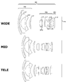
- FIG. 3 shows the lens configuration of the lens system 300 in the first embodiment, together with the image sensor 221.
- FIG. 3 shows the positions of the first lens group 301, the second lens group 302, and the third lens group 303 at the wide-angle end, the intermediate field angle, and the telephoto end, respectively.
- STO indicates an aperture.
- a plurality of surfaces of the lens system 300 are identified by a surface number i.
- the first surface of the lens as viewed from the object side is the first surface, and thereafter the surface numbers are counted up in the order in which the light passes through the surface.
- “Di” indicates an interval on the optical axis between the i-th surface and the (i + 1) -th surface.
- F indicates the focal length.
- Fno indicates an F number.
- ⁇ indicates a half angle of view.
- R indicates a radius of curvature. In the radius of curvature, “INF” indicates a plane.
- N represents a refractive index.
- V indicates the Abbe number.
- Table 1 shows lens data of lenses included in the lens system 300 in the first example.
- Di, n, and v are shown in association with the surface number i.
- a surface numbered with * is a surface having an aspherical shape.
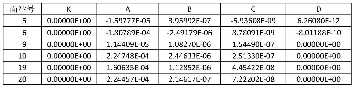
- Table 2 shows the surface number of the surface having the aspheric shape and the aspheric parameter.
- ⁇ represents a conic constant (conic constant).
- A”, “B”, “C”, and “D” are fourth-order, sixth-order, eighth-order, and tenth-order aspheric coefficients, respectively.
- Ei represents an exponential expression with 10 as the base. That is, “ Ei ” represents “10 ⁇ i ”. For example, “ ⁇ 1.59777E-05” represents “ ⁇ 1.59777 ⁇ 10 ⁇ 5 ”.
- the paraxial curvature is the reciprocal of the radius of curvature.
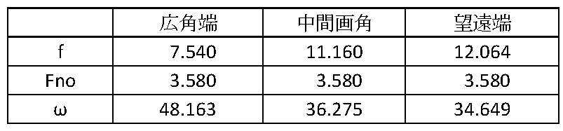
- Table 3 shows the focal length, F number, and half angle of view of the lens system 300 at each of the wide angle end, the intermediate angle of view, and the telephoto end.
- the focal length is a value for light having a wavelength of 546.07 nm.
- the surface distance D18 and the surface distance D20 between the third lens group 303 and the image sensor 221 can change.
- Table 4 shows the focal length and the surface interval of the entire lens system 300 at each of the wide angle end, the intermediate angle of view, and the telephoto end.
- Table 5 shows focal lengths of the first lens group 301, the second lens group 302, and the third lens group 303.
- FIG. 4 schematically shows a trajectory in which the first lens group 301, the second lens group 302, and the third lens group 303 move when the lens system 300 is zoomed from the wide-angle end to the telephoto end.
- the arrow indicates that the lens system 300 moves upon zooming.
- the distance from the first lens group 301 to the image sensor 221 is variable.
- the first lens group 301 has four lenses of a negative lens L1, a negative lens L2, a negative lens L3, and a positive lens L4 from the object side. This makes it possible to gently bend off-axis light rays on the wide angle side where the incident angle is particularly large. Therefore, it is possible to satisfactorily correct off-axis aberrations such as distortion, coma, and field curvature. In addition, the spherical aberration on the telephoto side can be corrected well. Further, since the negative refractive power of the first lens group 301 is shared by the three negative lenses L1 to L3, the negative refractive power of the first lens group 301 can be increased while suppressing aberrations. Further, the overall length of the lens system 300 can be shortened.
- the Abbe numbers v of the negative lenses L1 to L3 in the first lens group 301 all satisfy v> 60. More preferably, the Abbe numbers v of the negative lenses L1 to L3 all satisfy v> 65.
- the negative lens included in the first lens group 301 which is a negative lens, of a low dispersion glass material, the lateral chromatic aberration on the wide-angle side and the axial chromatic aberration on the telephoto side can be favorably corrected.
- the second lens group 302 includes a positive single lens L5, a stop STO, negative and positive cemented lenses L7 and L8, a positive single lens L9, and positive and negative cemented lenses L10 and L11 from the object side.
- the single lens L5 corresponds to the above-described 2a lens group.
- Negative and positive cemented lenses L7 and L8 correspond to the above-described second lens group b.
- the object-side surface and the image-side surface have an aspheric shape. By making at least one surface of the most object side positive single lens L5 an aspherical surface, spherical aberration can be corrected more favorably. Only one surface of the positive single lens L5 may have an aspheric shape.
- the stop STO is disposed between the positive single lens L5 and the negative and positive cemented lenses indicated by L7 and L8.
- the distance between the first lens group 301 having negative refractive power and the image sensor 221 is variable at the time of zooming from the wide-angle end to the telephoto end.
- the first lens group 301 monotonously moves toward the image sensor 221 when zooming from the wide-angle end to the telephoto end.
- the second lens group 302 monotonously moves from the image sensor 221 side to the object side during zooming from the wide-angle end to the telephoto end.
- the third lens group 303 moves monotonously toward the object side upon zooming from the wide angle end to the telephoto end.
- the second lens group 302 is responsible for the main variable magnification component
- the third lens group 303 is responsible for the secondary variable magnification component.
- the third lens group 303 is also responsible for correcting image plane fluctuations associated with zooming.
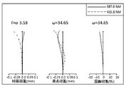
- FIG. 5 shows spherical aberration, astigmatism and distortion at the wide angle end.
- FIG. 6 shows spherical aberration, astigmatism and distortion at an intermediate angle of view.
- FIG. 7 shows spherical aberration, astigmatism and distortion at the telephoto end.
- the solid line indicates the value of the d-line (587.6 nm), and the broken line indicates the value of the g-line (435.8 nm).
- the solid line indicates the value of the sagittal image plane of the d line, and the broken line indicates the value of the meridional image plane of the d line.
- the distortion diagrams shown in FIGS. 5 to 7 show values for the d-line. From the respective aberration diagrams, it can be seen that the lens system 300 is excellent in various aberrations and has excellent imaging performance.
- FIG. 8 shows a spherical aberration diagram of the lens system 300 for light of three wavelengths.
- the alternate long and short dash line indicates the value of c-line (656.3 nm)
- the solid line indicates the value of d-line (587.6 nm)
- the broken line indicates the value of g-line (435.8 nm).
- the spherical aberration is within a range of 0.1 mm or less for each wavelength of light. Thereby, it can be seen that the chromatic aberration is corrected well.
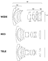
- FIG. 9 shows the lens configuration of the lens system 900 in the second embodiment together with the image sensor 221.
- the lens system 900 includes a first lens group 901, a second lens group 902, and a third lens group 903.
- the first lens group 901, the second lens group 902, and the third lens group 903 correspond to the first lens group 301, the second lens group 302, and the third lens group 303 in the lens system 300, respectively.
- symbols and the like used in the description of the lens system 900 have the same meanings as symbols and the like described in relation to the lens system 300 unless otherwise specified.
- FIG. 9 shows the positions of the first lens group 901, the second lens group 902, and the third lens group 903 at the wide-angle end, the intermediate field angle, and the telephoto end, respectively.
- Table 6 shows lens data of lenses included in the lens system 900.
- surfaces with * in the surface number are surfaces having an aspherical shape.
- Table 7 shows surfaces having an aspheric shape in the lens system 900 and aspheric parameters. “A”, “B”, “C”, and “D” are fourth-order, sixth-order, eighth-order, and tenth-order aspheric coefficients, respectively.
- Table 8 shows the focal length, F-number, and half angle of view of the lens system 900 at the wide angle end, the intermediate field angle, and the telephoto end, respectively.
- the focal length is a value for light having a wavelength of 546.07 nm.
- the surface distance D18 and the surface distance D20 between the third lens group 903 and the image sensor 221 can change.
- Table 9 shows the focal length and surface distance of the entire lens system 900 at the wide-angle end, the intermediate field angle, and the telephoto end, respectively.
- Table 10 shows the focal lengths of the first lens group 901, the second lens group 902, and the third lens group 903.
- FIG. 10 schematically shows the trajectories of the first lens group 901, the second lens group 902, and the third lens group 903 when the lens system 900 is zoomed from the wide-angle end to the telephoto end.
- the arrow indicates that the lens system 900 moves upon zooming.
- the interval from the first lens group 901 to the image sensor 221 is variable at the time of zooming.
- the first lens group 901 has four lenses, a negative lens L1, a negative lens L2, a negative lens L3, and a positive lens L4, from the object side.
- Li is a symbol for indicating that the lens is the i-th optical element from the object side. In the second example, even if the same symbol as the symbol Li assigned to the lens in the first example is assigned, it does not mean that the lens is the same.
- the first lens group 901 By configuring the first lens group 901 to include the four lenses of the negative lens L1, the negative lens L2, the negative lens L3, and the positive lens L4, off-axis rays on the wide-angle side where the incident angle is particularly large can be moderated. Can be bent. Therefore, it is possible to satisfactorily correct off-axis aberrations such as distortion, coma, and field curvature. In addition, the spherical aberration on the telephoto side can be corrected well. Further, since the negative refractive power of the first lens group 901 is shared by the three negative lenses L1 to L3, the negative refractive power of the first lens group 901 can be increased while suppressing aberrations. Further, the overall length of the lens system 900 can be shortened.
- the Abbe numbers v of the negative lenses L1 to L3 of the first lens group 901 are all v> 60.
- the second lens group 902 includes, from the object side, a positive single lens L5, a stop STO, negative and positive cemented lenses L7 and L8, a positive single lens L9, and positive and negative cemented lenses L10 and L11.
- the single lens L5 corresponds to the above-described 2a lens group.
- Negative and positive cemented lenses L7 and L8 correspond to the above-described second lens group b.
- the object-side surface and the image-side surface have an aspheric shape. By making at least one surface of the most object side positive single lens L5 an aspherical surface, spherical aberration can be corrected more favorably. Only one surface of the positive single lens L5 may have an aspheric shape.
- the stop STO is disposed between the positive single lens L5 and the negative and positive cemented lenses indicated by L7 and L8.
- the distance between the first lens group 901 having negative refractive power and the image sensor 221 is variable at the time of zooming from the wide-angle end to the telephoto end.
- the first lens group 901 moves monotonously toward the image sensor 221 when zooming from the wide-angle end to the telephoto end.
- the second lens group 902 moves monotonously from the image sensor 221 side to the object side during zooming from the wide-angle end to the telephoto end.
- the third lens group 903 moves monotonously to the object side during zooming from the wide-angle end to the telephoto end.
- the second lens group 902 is responsible for the main variable magnification component
- the third lens group 903 is responsible for the secondary variable magnification component.
- the third lens group 903 is also responsible for correcting image plane fluctuations accompanying zooming.
- FIG. 11 shows spherical aberration, astigmatism and distortion at the wide angle end.
- FIG. 12 shows spherical aberration, astigmatism and distortion at an intermediate angle of view.
- FIG. 13 shows spherical aberration, astigmatism and distortion at the telephoto end.
- the solid line shows the value of the d-line (587.6 nm), and the broken line shows the value of the g-line (435.8 nm).
- the solid line indicates the value of the sagittal image plane of the d line, and the broken line indicates the value of the meridional image plane of the d line.
- the distortion diagrams shown in FIGS. 11 to 13 show values for the d-line. From each aberration diagram, it can be seen that the lens system 900 has excellent imaging performance with various aberrations corrected well.
- FIG. 14 is a spherical aberration diagram for the three-wavelength light of the lens system 900.
- the alternate long and short dash line indicates the value of c-line (656.3 nm)
- the solid line indicates the value of d-line (587.6 nm)
- the broken line indicates the value of g-line (435.8 nm).
- the spherical aberration is within a range of 0.1 mm or less for each wavelength of light. It can be seen that the longitudinal chromatic aberration is corrected well.
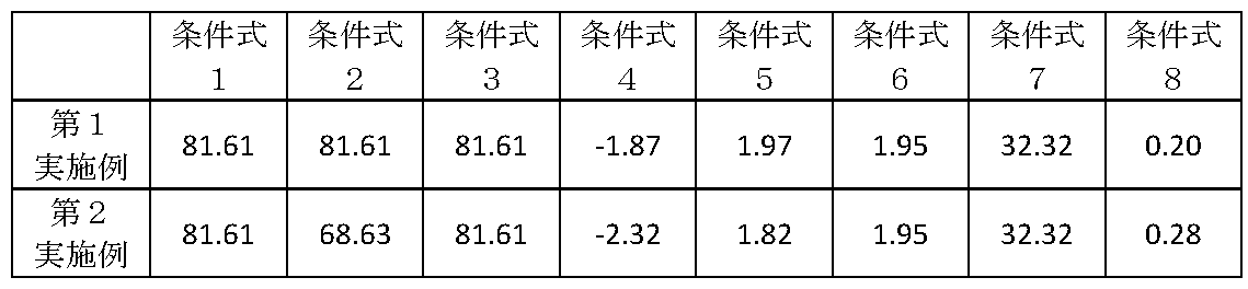
- Table 11 collectively shows numerical values according to the conditional expressions of the first and second embodiments.
- the numerical values associated with Conditional Expression 1, Conditional Expression 2, and Conditional Expression 3 indicate the Abbe numbers of the negative lens L1, the negative lens L2, and the negative lens L3, respectively.
- the numerical value associated with conditional expression 4 indicates the value of f1 / fw.
- the numerical value associated with conditional expression 5 indicates the value of f2 / fw.
- Numerical values associated with conditional expression 6 and conditional expression 7 indicate the refractive index and Abbe number of lenses having positive refractive power included in the first lens group 301, respectively.
- the numerical value associated with conditional expression 8 indicates Da / D2.
- the lens system 300 and the lens system 900 described above it is possible to provide a zoom lens having a high resolving power and a small size and a wide angle of view.
- a small-sized wide-angle zoom lens that has a small half field angle at the wide-angle end exceeding 45 degrees and high resolution.
- FIG. 15 is an external perspective view showing an example of the stabilizer 800.
- the stabilizer 800 is another example of the moving body.
- the camera unit 813 included in the stabilizer 800 may include an imaging device having the same configuration as the imaging device 220.
- the camera unit 813 may include a lens device having the same configuration as the lens device 160.
- the stabilizer 800 includes a camera unit 813, a gimbal 820, and a handle portion 803.
- the gimbal 820 supports the camera unit 813 in a rotatable manner.
- the gimbal 820 has a pan axis 809, a roll axis 810, and a tilt axis 811.
- the gimbal 820 supports the camera unit 813 so as to be rotatable about a pan axis 809, a roll axis 810, and a tilt axis 811.
- the gimbal 820 is an example of a support mechanism.
- the camera unit 813 is an example of an imaging device.
- the camera unit 813 has a slot 812 for inserting a memory.
- the gimbal 820 is fixed to the handle portion 803 via the holder 807.
- the handle portion 803 has various buttons for operating the gimbal 820 and the camera unit 813.
- the handle portion 803 includes a shutter button 804, a recording button 805, and an operation button 806. By pressing the shutter button 804, a still image can be recorded by the camera unit 813.
- the recording button 805 is pressed, a moving image can be recorded by the camera unit 813.
- the device holder 801 is fixed to the handle portion 803.
- the device holder 801 holds a mobile device 802 such as a smartphone.
- the mobile device 802 is communicably connected to the stabilizer 800 via a wireless network such as WiFi. Thereby, an image captured by the camera unit 813 can be displayed on the screen of the mobile device 802.
- the UAV 100 and the stabilizer 800 are taken up as an example of the moving body.
- An imaging device having a configuration similar to that of the imaging device 220 may be attached to a moving body other than the UAV 100 and the stabilizer.
- the imaging device attached to the moving body has been described.
- the imaging device having the same configuration as that of the imaging device 220 is not limited to the imaging device attached to the moving body.
- a configuration similar to that of the imaging device 220 can be applied to a non-lens interchangeable camera such as a so-called compact digital camera.
- the same configuration as the lens device 160 can be applied to an interchangeable lens of a lens interchangeable camera such as a single-lens reflex camera.
- the same configuration as the lens device 160 can be applied to the configurations of various lens devices for imaging.
Landscapes
- Physics & Mathematics (AREA)
- General Physics & Mathematics (AREA)
- Optics & Photonics (AREA)
- Nonlinear Science (AREA)
- Engineering & Computer Science (AREA)
- Multimedia (AREA)
- Signal Processing (AREA)
- Lenses (AREA)
Abstract
ズームレンズは、物体側より順に、負の屈折力を有する第1レンズ群と、正の屈折力を有する第2レンズ群と、正の屈折力を有する第3レンズ群とを備える。広角端から望遠端への変倍時に、第1レンズ群と第2レンズ群との間隔が減少し、第2レンズ群と第3レンズ群との間隔が変化する。第1レンズ群は、物体側から順に、それぞれ負、負、負、正の屈折力を有する4つのレンズを含む。第1レンズ群に含まれる負の屈折力を有する3つのレンズのアッベ数をそれぞれv1、v2、v3とし、第1レンズ群の焦点距離をf1、全系の広角端の焦点距離をfwとすると、条件式 v1>60、v2>60、v3>60、 -2.5 < f1/fw < -1.2を満足する。
Description
本発明は、ズームレンズ、撮像装置、移動体及びシステムに関する。
負-正-正の3群構成のズームレンズが知られている(例えば、特許文献1、2)。
特許文献1 国際公開第2012/066735号
特許文献2 特開2007-249087号公報
特許文献3 特開2014-98811号公報
特許文献1 国際公開第2012/066735号
特許文献2 特開2007-249087号公報
特許文献3 特開2014-98811号公報
画角が広く、色収差が補正された小型のズームレンズが望まれている。
本発明の一態様に係るズームレンズは、物体側より順に、負の屈折力を有する第1レンズ群と、正の屈折力を有する第2レンズ群と、正の屈折力を有する第3レンズ群とを備える。広角端から望遠端への変倍時に、第1レンズ群と第2レンズ群との間隔が減少し、第2レンズ群と第3レンズ群との間隔が変化する。第1レンズ群は、物体側から順に、それぞれ負、負、負、正の屈折力を有する4つのレンズを含む。第1レンズ群に含まれる負の屈折力を有する3つのレンズのアッベ数をそれぞれv1、v2、v3とし、第1レンズ群の焦点距離をf1、全系の広角端の焦点距離をfwとすると、条件式
v1>60
v2>60
v3>60
-2.5 < f1/fw < -1.2
を満足する。
v1>60
v2>60
v3>60
-2.5 < f1/fw < -1.2
を満足する。
第2レンズ群は、物体側に、少なくとも1つの正の屈折力を有する非球面レンズを含んでよい。第2レンズ群は、非球面レンズより像側に、少なくとも2つの接合レンズを含んでよい。少なくとも2つの接合レンズを構成する全ての正レンズのアッベ数vがv>60を満足してよい。第2レンズ群の焦点距離をf2とすると、条件式
1.3 < f2/fw < 2.6
を満足してよい。
1.3 < f2/fw < 2.6
を満足してよい。
第3レンズ群は、単一のレンズまたは接合レンズから構成され、フォーカス機能を担ってよい。
第1レンズ群に含まれる負の屈折力を有する3つのレンズのうち、物体側のレンズが球面レンズであってよい。当該物体側のレンズより像側に位置する2つのレンズのうちの少なくとも1つが非球面レンズであってよい。
第1レンズ群に含まれる正の屈折力を有するレンズの屈折率をn4、アッベ数をv4とすると、条件式
n4>1.9
v4<35
を満足してよい。
n4>1.9
v4<35
を満足してよい。
広角端から望遠端への変倍時に、第2レンズ群と一体的に移動する絞りを更に備えてよい。
第2レンズ群は、物体側より順に、第2aレンズ群と、絞りと、第2bレンズ群とを含んでよい。第2aレンズ群の最も物体側の面と最も像側の面との間の間隔をDa、第2レンズ群の最も物体側の面と最も像側の面との間の間隔をD2とすると、条件式
Da/D2 < 0.35
を満足してよい。
Da/D2 < 0.35
を満足してよい。
本発明の一態様に係る撮像装置は、上記のズームレンズと、撮像素子とを備える。
本発明の一態様に係る移動体は、上記のズームレンズを備えて移動する。
移動体は無人航空機であってよい。
本発明の一態様に係るシステムは、上記のズームレンズと、ズームレンズを変位可能に支持する支持機構と、支持機構に取り付けられている持ち手部とを備える。
上記のズームレンズによれば、画角が広く、収差が良好に補正された小型のズームレンズを提供できる。
上記の発明の概要は、本発明の特徴の全てを列挙したものではない。これらの特徴群のサブコンビネーションも発明となりうる。
以下、発明の実施の形態を通じて本発明を説明するが、以下の実施形態は請求の範囲に係る発明を限定するものではない。また、実施形態の中で説明されている特徴の組み合わせの全てが発明の解決手段に必須であるとは限らない。
請求の範囲、明細書、図面、及び要約書には、著作権による保護の対象となる事項が含まれる。著作権者は、これらの書類の何人による複製に対しても、特許庁のファイルまたはレコードに表示される通りであれば異議を唱えない。ただし、それ以外の場合、一切の著作権を留保する。
図1は、無人航空機(UAV)100及びコントローラ50を備える移動体システム10の一例を概略的に示す。UAV100は、UAV本体101、ジンバル110、複数の撮像装置230、及び撮像装置220を備える。撮像装置220は、レンズ装置160及び撮像部140を備える。UAV100は、撮像装置を備えて移動する移動体の一例である。移動体とは、UAVの他、空中を移動する他の航空機、地上を移動する車両、水上を移動する船舶等を含む概念である。
UAV本体101は、複数の回転翼を備える。UAV本体101は、複数の回転翼の回転を制御することでUAV100を飛行させる。UAV本体101は、例えば、4つの回転翼を用いてUAV100を飛行させる。回転翼の数は、4つには限定されない。UAV100は、回転翼を有さない固定翼機でもよい。
撮像装置230は、所望の撮像範囲に含まれる被写体を撮像する撮像用のカメラである。複数の撮像装置230は、UAV100の飛行を制御するためにUAV100の周囲を撮像するセンシング用のカメラである。撮像装置230は、UAV本体101に固定されていてよい。
2つの撮像装置230が、UAV100の機首である正面に設けられてよい。さらに他の2つの撮像装置230が、UAV100の底面に設けられてよい。正面側の2つの撮像装置230はペアとなり、いわゆるステレオカメラとして機能してよい。底面側の2つの撮像装置230もペアとなり、ステレオカメラとして機能してよい。複数の撮像装置230により撮像された画像に基づいて、UAV100の周囲の3次元空間データが生成されてよい。複数の撮像装置230により撮像された被写体までの距離は、複数の撮像装置230によるステレオカメラにより特定され得る。
UAV100が備える撮像装置230の数は4つには限定されない。UAV100は、少なくとも1つの撮像装置230を備えていればよい。UAV100は、UAV100の機首、機尾、側面、底面、及び天井面のそれぞれに少なくとも1つの撮像装置230を備えてもよい。撮像装置230は、単焦点レンズ又は魚眼レンズを有してもよい。UAV100に係る説明において、複数の撮像装置230を、単に撮像装置230と総称する場合がある。
コントローラ50は、表示部54と操作部52を備える。操作部52は、UAV100の姿勢を制御するための入力操作をユーザから受け付ける。コントローラ50は、操作部52が受け付けたユーザの操作に基づいて、UAV100を制御するための信号を送信する。例えば、操作部52は、レンズ装置160の倍率を変更する操作を受け付ける。コントローラ50は、倍率の変更を指示する信号をUAV100に送信する。
コントローラ50は、撮像装置230及び撮像装置220の少なくとも一方が撮像した画像を受信する。表示部54は、コントローラ50が受信した画像を表示する。表示部54はタッチ式のパネルであってよい。コントローラ50は、表示部54を通じて、ユーザから入力操作を受け付けてよい。表示部54は、撮像装置220に撮像させるべき被写体の位置をユーザが指定するユーザ操作等を受け付けてよい。
撮像部140は、レンズ装置160により結像された光学像の画像データを生成して記録する。レンズ装置160は、撮像部140と一体的に設けられてよい。レンズ装置160は、いわゆる交換レンズであってよい。レンズ装置160は、撮像部140に対して着脱可能に設けられてよい。
ジンバル110は、撮像装置220を可動に支持する支持機構を有する。撮像装置220は、ジンバル110を介してUAV本体101に取り付けられる。ジンバル110は、撮像装置220を、ピッチ軸を中心に回転可能に支持する。ジンバル110は、撮像装置220を、ロール軸を中心に回転可能に支持する。ジンバル110は、撮像装置220を、ヨー軸を中心に回転可能に支持する。ジンバル110は、ピッチ軸、ロール軸、及びヨー軸の少なくとも1つの軸を中心に、撮像装置220を回転可能に支持してよい。ジンバル110は、ピッチ軸、ロール軸、及びヨー軸のそれぞれを中心に、撮像装置220を回転可能に支持してよい。ジンバル110は、撮像部140を保持してもよい。ジンバル110は、レンズ装置160を保持してもよい。ジンバル110は、ヨー軸、ピッチ軸、及びロール軸の少なくとも1つを中心に撮像部140及びレンズ装置160を回転させることで、撮像装置220の撮像方向を変更してよい。
図2は、UAV100の機能ブロックの一例を示す。UAV100は、インタフェース102、制御部104、メモリ106、ジンバル110、撮像部140、及びレンズ装置160を備える。
インタフェース102は、コントローラ50と通信する。インタフェース102は、コントローラ50から各種の命令を受信する。制御部104は、コントローラ50から受信した命令に従って、UAV100の飛行を制御する。制御部104は、ジンバル110、撮像部140、及びレンズ装置160を制御する。制御部104は、CPU又はMPUなどのマイクロプロセッサ、MCUなどのマイクロコントローラなどにより構成されてよい。メモリ106は、制御部104がジンバル110、撮像部140、及びレンズ装置160を制御するのに必要なプログラムなどを格納する。
メモリ106は、コンピュータが可読な記録媒体でよい。メモリ106は、SRAM、DRAM、EPROM、EEPROM、及びUSBメモリなどのフラッシュメモリの少なくとも1つを含んでよい。メモリ106は、UAV100の筐体に設けられてよい。UAV100の筐体から取り外し可能に設けられてよい。
ジンバル110は、制御部112、ドライバ114、ドライバ116、ドライバ118、駆動部124、駆動部126、駆動部128、及び支持機構130を有する。駆動部124、駆動部126及び駆動部128は、モータであってよい。
支持機構130は、撮像装置220を支持する。支持機構130は、撮像装置220の撮像方向を可動に支持する。支持機構130は、撮像部140及びレンズ装置160をヨー軸、ピッチ軸、及びロール軸を中心に回転可能に支持する。支持機構130は、回転機構134、回転機構136、及び回転機構138を含む。回転機構134は、駆動部124を用いてヨー軸を中心に撮像部140及びレンズ装置160を回転させる。回転機構136は、駆動部126を用いてピッチ軸を中心に撮像部140及びレンズ装置160を回転させる。回転機構138は、駆動部128を用いてロール軸を中心に撮像部140及びレンズ装置160を回転させる。
制御部112は、制御部104からのジンバル110の動作命令に応じて、ドライバ114、ドライバ116、及びドライバ118に対して、それぞれの回転角度を示す動作命令を出力する。ドライバ114、ドライバ116、及びドライバ118は、回転角度を示す動作命令に従って駆動部124、駆動部126、及び駆動部128を駆動させる。回転機構134、回転機構136、及び回転機構138は、駆動部124、駆動部126、及び駆動部128によりそれぞれ駆動されて回転し、撮像部140及びレンズ装置160の姿勢を変更する。
撮像部140は、レンズ系300を通過した光により撮像する。撮像部140は、制御部222、撮像素子221及びメモリ223を備える。制御部222は、CPU又はMPUなどのマイクロプロセッサ、MCUなどのマイクロコントローラなどにより構成されてよい。制御部222は、制御部104からの撮像部140及びレンズ装置160に対する動作命令に応じて、撮像部140及びレンズ装置160を制御する。制御部222は、コントローラ50から受信した信号に基づいて、レンズ装置160に変倍を指示する制御命令をレンズ装置160に出力する。
メモリ223は、コンピュータが可読な記録媒体でよく、SRAM、DRAM、EPROM、EEPROM、及びUSBメモリなどのフラッシュメモリの少なくとも1つを含んでよい。メモリ223は、撮像部140の筐体の内部に設けられてよい。撮像部140の筐体から取り外し可能に設けられてよい。
撮像素子221は、撮像部140の筐体の内部に保持され、レンズ装置160を介して結像された光学像の画像データを生成して、制御部222に出力する。制御部222は、撮像素子221から出力された画像データをメモリ223に格納する。制御部222は、画像データを、制御部104を介してメモリ106に出力して格納してもよい。
レンズ装置160は、ズームレンズである。レンズ装置160は、全長可変のズームレンズである。レンズ装置160は、比較的に広角のズームレンズである。レンズ装置160は、3群ズームレンズである。レンズ装置160は、制御部162、メモリ163、駆動機構161、及びレンズ系300を備える。レンズ系300は、物体側から順に、第1レンズ群301、第2レンズ群302及び第3レンズ群303を備える。本実施形態の説明において、レンズ系300の光軸のことを、単に「光軸」と呼ぶ場合がある。また、「レンズ群」とは、1つ以上のレンズのまとまりのことをいう。単一のレンズから構成されるレンズのことも「レンズ群」と呼ぶ。
制御部162は、制御部222からの制御命令に従って、第1レンズ群301、第2レンズ群302及び第3レンズ群303の少なくとも一つを光軸に沿って移動させる。例えば、第2制御部162は、変倍時に、第1レンズ群301、第2レンズ群302及び第3レンズ群303を光軸に沿って移動させる。これにより、変倍時にピント位置の移動が生じないようにする。レンズ装置160のレンズ系300により結像された像は、撮像部140により撮像される。
駆動機構161は、第1レンズ群301、第2レンズ群302及び第3レンズ群303を駆動する。駆動機構161は、例えばアクチュエータと、第1レンズ群301、第2レンズ群302及び第3レンズ群303を保持する保持部材とを備える。アクチュエータには、制御部162から駆動用のパルスが供給される。アクチュエータは、供給されたパルスに応じた駆動量だけ変位する。アクチュエータの変位に応じて保持部材が変位することにより、第1レンズ群301、第2レンズ群302及び第3レンズ群303が変位する。
レンズ装置160は、撮像部140と一体的に設けられてよい。レンズ装置160は、いわゆる交換レンズであってよい。レンズ装置160は、撮像部140に対して着脱可能に設けられてよい。
撮像装置230は、制御部232、制御部234、撮像素子231、メモリ233、及びレンズ235を備える。制御部232は、CPU又はMPUなどのマイクロプロセッサ、MCUなどのマイクロコントローラなどにより構成されてよい。制御部232は、制御部104からの撮像素子231の動作命令に応じて、撮像素子231を制御する。
制御部234は、CPU又はMPUなどのマイクロプロセッサ、MCUなどのマイクロコントローラなどにより構成されてよい。制御部234は、制御部104からのレンズ235に対する動作命令に応じて、レンズ235の焦点距離を制御する。制御部234は、レンズ235に対する動作命令に応じて、レンズ235の焦点を制御してよい。制御部234は、レンズ235に対する動作命令に応じて、レンズ235が有する絞りを制御してよい。
メモリ233は、コンピュータが可読な記録媒体であってよい。メモリ233は、SRAM、DRAM、EPROM、EEPROM、及びUSBメモリなどのフラッシュメモリの少なくとも1つを含んでよい。
撮像素子231は、レンズ235を介して結像された光学像の画像データを生成して、制御部232に出力する。制御部232は、撮像素子231から出力された画像データをメモリ233に格納する。
本実施形態では、UAV100が、制御部104、制御部112、制御部222、制御部232、制御部234、及び制御部162を備える例について説明する。しかし、制御部104、制御部112、制御部222、制御部232、制御部234、及び制御部162のうちの複数で実行される処理をいずれか1つの制御部が実行してよい。制御部104、制御部112、制御部222、制御部232、制御部234、及び制御部162で実行される処理を1つの制御部で実行してもよい。本実施形態では、UAV100が、メモリ106、メモリ223、及びメモリ233を備える例について説明する。メモリ106、メモリ223、及びメモリ233のうちの少なくとも1つに記憶される情報は、メモリ106、メモリ223、及びメモリ233のうちの他の1つ又は複数のメモリに記憶してよい。
レンズ系300において、第1レンズ群301は、負屈折力を有する。第2レンズ群302は、正屈折力を有する。第3レンズ群303は、正屈折力を有する。第1レンズ群301、第2レンズ群302及び第3レンズ群303は、物体側より、第1レンズ群301、第2レンズ群302及び第3レンズ群303の順で設けられる。なお、本実施形態の説明においてレンズ系300の変倍時の挙動を説明する場合、無限遠の被写体に対してレンズ装置160をズームレンズとして機能させる場合の挙動を示す。
広角端から望遠端への変倍時に、第1レンズ群301と第2レンズ群302との間隔は減少する。広角端から望遠端への変倍時に、第2レンズ群302と第3レンズ群303との間隔が変化する。広角端から望遠端への変倍時に、第2レンズ群302と第3レンズ群303との間隔が増加してよい。広角端から望遠端への変倍時に、第2レンズ群302と第3レンズ群303との間隔が減少してよい。
第1レンズ群301は、物体側から順に、それぞれ負、負、負、正の屈折力を有する4つのレンズを含む。第1レンズ群301に含まれる負の屈折力を有する3つのレンズのアッベ数をそれぞれv1、v2、v3とし、条件式
v1>60 (条件式1)
v2>60 (条件式2)
v3>60 (条件式3)
を満足する。
v1>60 (条件式1)
v2>60 (条件式2)
v3>60 (条件式3)
を満足する。
第1レンズ群301において、負の屈折力を有する3つのレンズで負屈折力を分担することができるので、第1レンズ群301の全体の負屈折力を高めることができる。レンズ系300の全長を短くすることができる。また、結像特性を高めることができる。負の屈折力を有する3つのレンズで第1レンズ群301の負屈折力を分担することで、低分散材を用いて負の屈折力を持つレンズを形成することができる。これにより、色収差をより強く補正することができる。なお、色収差をより強く補正するためには、v1>65、v2>65、及びv3>65を満たすことが望ましい。
第1レンズ群301の焦点距離をf1、全系(レンズ系300)の広角端の焦点距離をfwとすると、
-2.5 < f1/fw < -1.2 (条件式4)
を満足する。
-2.5 < f1/fw < -1.2 (条件式4)
を満足する。
条件式4の上限を満足する、すなわち、第1レンズ群301の屈折力を所定の下限閾値より高くすることで、レンズ系300を小型化することができる。条件式4の下限を満足する、すなわち第1レンズ群301の屈折力を所定の上限閾値以上にならないようにすることで、結像特性を高めることができる。
レンズ系300によれば、負正正の3群構成とし、上記条件式を満足することで、小型でありながら広角で高い結像特性を持つレンズ系を実現できる。
なお、広角端から望遠端への変倍時に、第1レンズ群301は撮像素子221に対して移動する。広角端から望遠端への変倍時に、第1レンズ群301と撮像素子221との間の間隔が減少する。広角端から望遠端への変倍時に、広角端における画角から望遠端における画角までの全範囲において、第1レンズ群301と撮像素子221との間の間隔が減少する。なお、広角端から望遠端への変倍時に、広角端における画角から予め定められた画角までの範囲においてのみ、第1レンズ群301と撮像素子221との間の間隔が減少してよい。
第2レンズ群302は、物体側に、少なくとも1つの正の屈折力を有する非球面レンズを含んでよい。
第2レンズ群302の正の屈折力を大きくするためには、第2レンズ群302を構成する各レンズの正屈折力を大きくする必要がある。ここで、特に物体側のレンズの正の屈折力を大きくすることで、望遠時におけるレンズ系300の全長を短くすることができる。更に、当該大きい屈折力を持つレンズとして非球面レンズを用いることで、収差を効果的に補正することが可能となる。
第2レンズ群302は、上記物体側の非球面レンズより像側に、少なくとも2つの接合レンズを含んでよい。当該少なくとも2つの接合レンズを構成する全ての正レンズのアッベ数vがv>60を満足してよい。
第2レンズ群302を構成する正の屈折力を有するレンズのアッベ数を全て60以上にすることで、第2レンズ群302の屈折力を大きくしつつ、色収差を抑制することができる。これにより、結像特性を高めつつ、レンズ系300を小型化することができる。
第2レンズ群302の焦点距離をf2とすると、条件式
1.3 < f2/fw < 2.6(条件式5)
を満足してよい。
1.3 < f2/fw < 2.6(条件式5)
を満足してよい。
条件式5の上限を満足する、すなわち、第2レンズ群302の屈折力を所定の下限閾値より大きくすることで、レンズ系300を小型化することができる。条件式5の下限を満足する、すなわち、第2レンズ群302の屈折力を所定の上限閾値以上にならないようにすることで、結像特性を高めることができる。
第3レンズ群303は、単一のレンズまたは接合レンズから構成されてよい。第3レンズ群303は、フォーカス機能を担ってよい。第3レンズ群303は、レンズ系300におけるフォーカス機能の少なくとも一部を担ってよい。第3レンズ群303は、レンズ系300におけるフォーカス機能の主成分を担ってよい。
フォーカス機能を実現するには、いずれかのレンズ群を駆動することが必要となる。レンズ系300においては、フォーカス機能を担うレンズ群を単一のレンズ又は接合レンズとすることで、レンズの駆動機構を簡素化することができる。また、レンズの駆動素子を軽量化することができる。ひいてはレンズ系300全体の小型化に寄与する。
第3レンズ群303は、レンズ系300における防振機能を担ってよい。第3レンズ群303は、フォーカス機能に加えて、防振機能を担ってよい。光学的な防振機能を実現するには、いずれかのレンズ群を駆動することが必要となる。レンズ系300においては、防振機能を担うレンズ群を単一のレンズ又は接合レンズとすることで、レンズの駆動機構を簡素化することができる。また、レンズの駆動素子を軽量化することができる。ひいてはレンズ系300全体の小型化に寄与する。
第1レンズ群301に含まれる負の屈折力を有する3つのレンズのうち、物体側のレンズが球面レンズであってよい。当該物体側のレンズより像側に位置する2つのレンズのうちの少なくとも1つが非球面レンズであってよい。
物体側のレンズの位置では、軸上光線と周辺光線の高さの差が大きくなる。レンズ系300において最も物体側に位置する第1レンズ群301において、像側に位置する2つのレンズのうちの少なくとも1つを非球面レンズにすることで、歪曲収差や像面湾曲を効果的に補正することができる。また、有効径が大きい物体側のレンズを球面レンズにすることで、物体側のレンズを非球面レンズにする場合に比べて、コストを削減することができる。
第1レンズ群301に含まれる正の屈折力を有するレンズの屈折率をn4、アッベ数をv4とすると、条件式
n4>1.9 (条件式6)
v4<35 (条件式7)
を満足してよい。
n4>1.9 (条件式6)
v4<35 (条件式7)
を満足してよい。
第1レンズ群301の正の屈折力を有するレンズが上記条件式6、条件式7を満足することで、第1レンズ群301の光軸方向の厚みを薄くすることができる。これにより、レンズ系300の全長の短縮化に寄与する。
第2レンズ群302は、物体側より順に、第2aレンズ群と、絞りと、第2bレンズ群とを含んでよい。第2aレンズ群の最も物体側の面と最も像側の面との間の間隔をDa、第2レンズ群302の最も物体側の面と最も像側の面との間の間隔をD2とすると、条件式
Da/D2 < 0.35 (条件式8)
を満足する。
Da/D2 < 0.35 (条件式8)
を満足する。
レンズ系300は、広角端から望遠端への変倍時に、第2レンズ群302と一体的に移動する絞りを備えてよい。
第2レンズ群302において、第2aレンズ群の光軸上の間隔が条件式を満足することにより、絞りを物体側に位置することができる。これにより、第1レンズ群301のレンズ径を小さくすることができる。
以上に説明したレンズ系300によれば、色収差等の収差が良好に補正され、高い解像力を有する小型で広画角なズームレンズを提供することができる。例えば、広角端の半画角が45度を超える小型で解像力が高い広角ズームレンズを提供し得る。
図3は、第1実施例におけるレンズ系300のレンズ構成を、撮像素子221とともに示す。図3は、広角端、中間画角、及び望遠端のそれぞれにおける第1レンズ群301、第2レンズ群302及び第3レンズ群303の位置を示す。なお、STOは絞りを示す。
ここで、レンズ系300の実施例の説明で用いられる記号等の意味を説明する。レンズ系300が有する複数の面は、面番号iで識別される。物体側からみてレンズの最初の面を第1面とし、以降、光線が面を通過する順に面番号をカウントアップする。「Di」は、第i番目の面と第i+1番目の面との間の光軸上の間隔を示す。
「f」は焦点距離を示す。「Fno」はFナンバーを示す。「ω」は半画角を示す。「R」は曲率半径を示す。曲率半径において、「INF」は平面であることを示す。「n」は屈折率を示す。「v」は、アッベ数を示す。屈折率n及びアッベ数vは、d線(λ=587.6nm)における値である。
表1は、第1実施例におけるレンズ系300が有するレンズのレンズデータを示す。なお、表1において、Di、n及びvは面番号iに対応づけて示されている。

表1において、面番号に*が付されている面は、非球面形状を有する面である。表2は、非球面形状を有する面の面番号と、非球面パラメータとを示す。表2において、「κ」は、円錐定数(コーニック定数)を示す。「A」、「B」、「C」、及び「D」は、それぞれ4次、6次、8次、及び10次の非球面係数である。また、非球面係数において、「E-i」は10を底とする指数表現を示す。すなわち、「E-i」は、「10-i」を表す。例えば、「-1.59777E-05」は、「-1.59777×10⁻⁵」を表す。
「x」をレンズ面の頂点からの光軸方向における距離とし、「y」を光軸に垂直な方向における高さとし、「c」をレンズの頂点における近軸曲率とした場合、非球面形状は次の式によって定義される。
x=cy2/(1+(1-(1+κ)c2y2)1/2)+Ay4+By6+Cy8+Dy10
なお、「x」はサグ量とも呼ばれる。「y」は像高とも呼ばれる。近軸曲率は、曲率半径の逆数である。
x=cy2/(1+(1-(1+κ)c2y2)1/2)+Ay4+By6+Cy8+Dy10
なお、「x」はサグ量とも呼ばれる。「y」は像高とも呼ばれる。近軸曲率は、曲率半径の逆数である。
表3は、広角端、中間画角及び望遠端のそれぞれにおけるレンズ系300の焦点距離、Fナンバー及び半画角を示す。なお、焦点距離は、波長546.07nmの光についての値である。
レンズ系300における広角端と望遠端との間の変倍に際して、第1レンズ群301と第2レンズ群302との間の面間隔D8、第2レンズ群302と第3レンズ群303との間の面間隔D18、第3レンズ群303と撮像素子221との間の面間隔D20が変化し得る。表4は、広角端、中間画角及び望遠端のそれぞれにおける、レンズ系300の全系の焦点距離及び面間隔を示す。

表5は、第1レンズ群301、第2レンズ群302及び第3レンズ群303のそれぞれの焦点距離を示す。
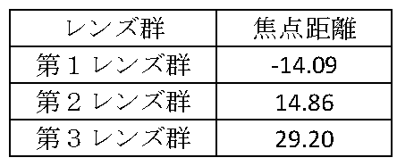
図4は、レンズ系300を広角端から望遠端への変倍時に第1レンズ群301、第2レンズ群302及び第3レンズ群303が移動する軌跡を模式的に示す。矢印は、レンズ系300の変倍に際して移動することを示す。図3及び図4に示されるように、第1レンズ群301から撮像素子221までの間隔が可変である。
第1レンズ群301は、物体側より、負レンズL1、負レンズL2、負レンズL3及び正レンズL4の4枚のレンズを有する。これにより、特に入射角が大きくなる広角側の軸外光線を緩やかに曲げることができる。したがって、歪曲収差、コマ収差、及び像面湾曲などの軸外収差を良好に補正することができる。また、望遠側の球面収差を良好に補正することができる。また、第1レンズ群301が持つ負の屈折力を3枚の負レンズL1~L3で分担するので、収差を抑えながら第1レンズ群301の負の屈折力を大きくすることができる。また、レンズ系300の全長を短くすることができる。
第1レンズ群301の負レンズL1~L3のアッベ数vは、全てv>60を満たすことが望ましい。負レンズL1~L3のアッベ数vは、全てv>65を満たすことがより好ましい。負レンズである第1レンズ群301に含まれる負レンズを低分散硝材で形成することで、広角側の倍率色収差及び望遠側の軸上色収差を良好に補正することができる。
第2レンズ群302は、物体側より正の単レンズL5、絞りSTO、負正の接合レンズL7及びL8、正の単レンズL9、及び正負の接合レンズL10及びL11を有する。単レンズL5は、上述した第2aレンズ群に対応する。負正の接合レンズL7及びL8は、上述した第2bレンズ群に対応する。正の単レンズL5は、物体側の面及び像面側の面が非球面形状を有する。最も物体側の正の単レンズL5の少なくとも一面を非球面にすることで、球面収差をより良好に補正することができる。なお、正の単レンズL5の一方の面のみが非球面形状を有してよい。
なお、絞りSTOは、正の単レンズL5と、L7及びL8で示される負正の接合レンズとの間に配置している。このように配置することで、望遠側で第1レンズ群301と第2レンズ群302との間隔を短くすることが出来る。そのため、レンズ系300の全長が短くすることができる。
図3及び図4に示されるように、負の屈折力を持つ第1レンズ群301と撮像素子221との間隔は、広角端から望遠端への変倍時に可変である。第1レンズ群301は、広角端から望遠端への変倍時に撮像素子221側へ単調に移動する。第2レンズ群302は、広角端から望遠端への変倍時に撮像素子221側から物体側へ単調に移動する。第3レンズ群303は、広角端から望遠端への変倍時に、物体側へ単調に移動する。第2レンズ群302が主変倍成分を担い、第3レンズ群303が副変倍成分を担う。第3レンズ群303は、変倍に伴う像面変動の補正も担う。
図5は、広角端における球面収差、非点収差及び歪曲収差を示す。図6は、中間画角における球面収差、非点収差及び歪曲収差を示す。図7は、望遠端における球面収差、非点収差及び歪曲収差を示す。
図5から図7に示す球面収差図において、実線はd線(587.6nm)の値を示し、破線はg線(435.8nm)の値を示す。図5から図7に示す非点収差図において、実線はd線のサジタル像面の値を示し、破線はd線のメリディオナル像面の値を示す。図5から図7に示す歪曲収差図は、d線についての値を示す。各収差図から、レンズ系300は諸収差が良好に補正され、優れた結像性能を有していることが分かる。
図8は、3波長の光についてのレンズ系300の球面収差図を示す。一点鎖線はc線(656.3nm)、実線はd線(587.6nm)、破線はg線(435.8nm)の値を示す。広角端、中間画角、望遠端ともに、各波長の光について球面収差が0.1mm以内の範囲に収まっている。これにより、色収差が良好に補正されていることが分かる。
図9は、第2実施例におけるレンズ系900のレンズ構成を、撮像素子221とともに示す。レンズ系900は、第1レンズ群901と、第2レンズ群902と、第3レンズ群903とを備える。第1レンズ群901、第2レンズ群902及び第3レンズ群903は、それぞれ、レンズ系300における第1レンズ群301、第2レンズ群302及び第3レンズ群303に対応する。レンズ系900に関する説明において、レンズ系900が有する特徴のうち、レンズ系300との相違点のみを説明し、同様の特徴については省略する場合がある。また、レンズ系900の説明で用いられる記号等は、特に説明しない限り、レンズ系300に関連して説明した記号等の意味と同じである。
図9には、広角端、中間画角、及び望遠端のそれぞれにおける第1レンズ群901、第2レンズ群902及び第3レンズ群903の位置が示されている。
表6は、レンズ系900が有するレンズのレンズデータを示す。
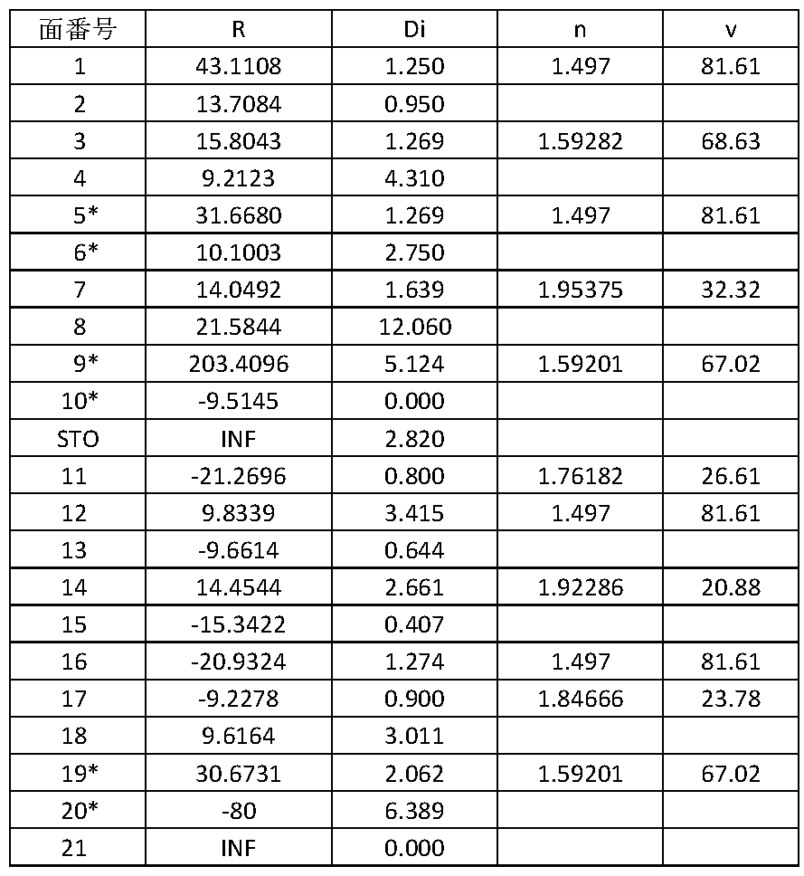
表6において、面番号に*が付されている面は、非球面形状を有する面である。表7は、レンズ系900において非球面形状を有する面と、非球面パラメータとを示す。「A」、「B」、「C」、「D」は、それぞれ4次、6次、8次、及び10次の非球面係数である。
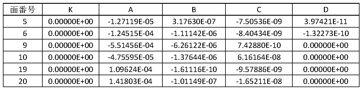
表8は、広角端、中間画角及び望遠端のそれぞれにおけるレンズ系900の焦点距離、Fナンバー及び半画角を示す。なお、焦点距離は、波長546.07nmの光についての値である。
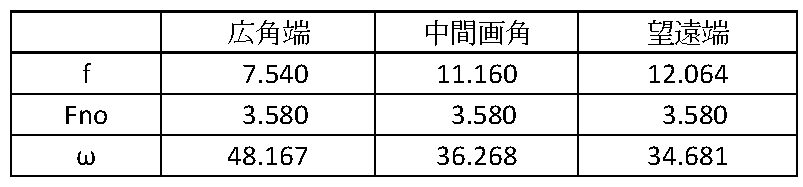
レンズ系900における広角端と望遠端との間の変倍に際して、第1レンズ群901と第2レンズ群902との間の面間隔D8、第2レンズ群902と第3レンズ群903との間の面間隔D18、第3レンズ群903と撮像素子221との間の面間隔D20が変化し得る。表9は、広角端、中間画角及び望遠端のそれぞれにおける、レンズ系900の全系の焦点距離及び面間隔を示す。

表10は、第1レンズ群901、第2レンズ群902及び第3レンズ群903のそれぞれの焦点距離を示す。
図10は、レンズ系900を広角端から望遠端への変倍時に第1レンズ群901、第2レンズ群902及び第3レンズ群903が移動する軌跡を模式的に示す。矢印は、レンズ系900の変倍に際して移動することを示す。図9及び図10に示されるように、第1レンズ群901から撮像素子221までの間隔は、変倍時に可変である。
第1レンズ群901は、物体側より、負レンズL1、負レンズL2、負レンズL3及び正レンズL4の4枚のレンズを有する。なお、第2実施例において、Liは、物体側からi番目の光学要素のレンズであることを示すための記号である。第2実施例において、第1実施例においてレンズに割り当てられた記号Liと同じ記号が割り当てられていても、同じレンズであることを意味しない。
第1レンズ群901を、負レンズL1、負レンズL2、負レンズL3及び正レンズL4の4枚のレンズを含んで構成することで、特に入射角が大きくなる広角側の軸外光線を緩やかに曲げることができる。したがって、歪曲収差、コマ収差、及び像面湾曲などの軸外収差を良好に補正することができる。また、望遠側の球面収差を良好に補正することができる。また、第1レンズ群901が持つ負の屈折力を3枚の負レンズL1~L3で分担するので、収差を抑えながら第1レンズ群901の負の屈折力を大きくすることができる。また、レンズ系900の全長を短くすることができる。
第1レンズ群901の負レンズL1~L3のアッベ数vは、全てv>60であることが望ましい。負レンズである第1レンズ群901に含まれる負レンズを低分散硝材で形成することで、広角側の倍率色収差及び望遠側の軸上色収差を良好に補正することができる。
第2レンズ群902は、物体側より、正の単レンズL5、絞りSTO、負正の接合レンズL7及びL8、正の単レンズL9、及び正負の接合レンズL10及びL11を有する。単レンズL5は、上述した第2aレンズ群に対応する。負正の接合レンズL7及びL8は、上述した第2bレンズ群に対応する。正の単レンズL5は、物体側の面及び像面側の面が非球面形状を有する。最も物体側の正の単レンズL5の少なくとも一面を非球面にすることで、球面収差をより良好に補正することができる。なお、正の単レンズL5の一方の面のみが非球面形状を有してよい。
なお、絞りSTOは、正の単レンズL5と、L7及びL8で示される負正の接合レンズとの間に配置している。このように配置することで、望遠側で第1レンズ群301と第2レンズ群302との間隔を短くすることが出来る。そのため、レンズ系900の全長が短くすることができる。
図9及び図10に示されるように、負の屈折力を持つ第1レンズ群901と撮像素子221との間隔は、広角端から望遠端への変倍時に可変である。第1レンズ群901は、広角端から望遠端への変倍時に撮像素子221側へ単調に移動する。第2レンズ群902は、広角端から望遠端への変倍時に撮像素子221側から物体側へ単調に移動する。第3レンズ群903は、広角端から望遠端への変倍時に、物体側へ単調に移動する。第2レンズ群902が主変倍成分を担い、第3レンズ群903が副変倍成分を担う。第3レンズ群903は、変倍に伴う像面変動の補正も担う。
図11は、広角端における球面収差、非点収差及び歪曲収差を示す。図12は、中間画角における球面収差、非点収差及び歪曲収差を示す。図13は、望遠端における球面収差、非点収差及び歪曲収差を示す。
図11から図13に示す球面収差図において、実線はd線(587.6nm)の値を示し、破線はg線(435.8nm)の値を示す。図11から図13に示す非点収差図において、実線はd線のサジタル像面の値を示し、破線はd 線のメリディオナル像面の値を示す。図11から図13に示す歪曲収差図は、d線についての値を示す。各収差図から、レンズ系900は諸収差が良好に補正され、優れた結像性能を有していることが分かる。
図14は、レンズ系900の3波長の光についての球面収差図を示す。一点鎖線はc線(656.3nm)、実線はd線(587.6nm)、破線はg線(435.8nm)の値を示す。広角端、中間画角、望遠端ともに、各波長の光について球面収差が0.1mm以内の範囲に収まっている。軸上色収差が良好に補正されていることが分かる。
表11は、第1実施例及び第2実施例の条件式に係る数値をまとめて示す。表11において条件式1、条件式2及び条件式3に対応づけられた数値は、それぞれ負レンズL1、負レンズL2及び負レンズL3のアッベ数を示す。条件式4に対応づけられた数値は、f1/fwの値を示す。条件式5に対応づけられた数値は、f2/fwの値を示す。条件式6及び条件式7に対応づけられた数値は、それぞれ第1レンズ群301に含まれる正の屈折力を有するレンズの屈折率及びアッベ数を示す。条件式8に対応づけられた数値は、Da/D2を示す。
以上に説明したレンズ系300及びレンズ系900によれば、高い解像力を有し、小型で広画角なズームレンズを提供することができる。例えば、広角端の半画角が45度を超える小型で解像力が高い広角ズームレンズを提供し得る。
図15は、スタビライザ800の一例を示す外観斜視図である。スタビライザ800は、移動体の他の一例である。例えば、スタビライザ800が備えるカメラユニット813が、撮像装置220と同様の構成の撮像装置を備えてよい。カメラユニット813が、レンズ装置160と同様の構成のレンズ装置を備えてよい。
スタビライザ800は、カメラユニット813、ジンバル820、及び持ち手部803を備える。ジンバル820は、カメラユニット813を回転可能に支持する。ジンバル820は、パン軸809、ロール軸810、及びチルト軸811を有する。ジンバル820は、パン軸809、ロール軸810、及びチルト軸811を中心に、カメラユニット813を回転可能に支持する。ジンバル820は、支持機構の一例である。
カメラユニット813は、撮像装置の一例である。カメラユニット813は、メモリを挿入するためのスロット812を有する。ジンバル820は、ホルダ807を介して持ち手部803に固定される。
持ち手部803は、ジンバル820、カメラユニット813を操作するための各種ボタンを有する。持ち手部803は、シャッターボタン804、録画ボタン805、及び操作ボタン806を含む。シャッターボタン804が押下されることで、カメラユニット813により静止画を記録することができる。録画ボタン805が押下されることで、カメラユニット813により動画を記録することができる。
デバイスホルダ801が持ち手部803に固定されている。デバイスホルダ801は、スマートフォンなどのモバイルデバイス802を保持する。モバイルデバイス802は、WiFiなどの無線ネットワークを介してスタビライザ800と通信可能に接続される。これにより、カメラユニット813により撮像された画像をモバイルデバイス802の画面に表示させることができる。
スタビライザ800においても、カメラユニット813がスタビライザ800の他の部位と干渉することを抑制できる。
以上、移動体の一例としてUAV100及びスタビライザ800を取り上げて説明した。撮像装置220と同様の構成を有する撮像装置は、UAV100及びスタビライザ以外の移動体に取り付けられてよい。
以上において、移動体に取り付けられる撮像装置について説明した。しかし、撮像装置220と同様の構成を有する撮像装置は、移動体に取り付けられる撮像装置に限られない。撮像装置220と同様の構成は、いわゆるコンパクトデジタルカメラ等のレンズ非交換式のカメラに適用できる。レンズ装置160と同様の構成は、一眼レフレックスカメラ等のレンズ交換式カメラの交換レンズに適用できる。レンズ装置160と同様の構成は、撮像用の様々なレンズ装置の構成に適用できる。
以上、本発明を実施の形態を用いて説明したが、本発明の技術的範囲は上記実施の形態に記載の範囲には限定されない。上記実施の形態に、多様な変更または改良を加えることが可能であることが当業者に明らかである。その様な変更または改良を加えた形態も本発明の技術的範囲に含まれ得ることが、請求の範囲の記載から明らかである。
請求の範囲、明細書、および図面中において示した装置、システム、プログラム、および方法における動作、手順、ステップ、および段階等の各処理の実行順序は、特段「より前に」、「先立って」等と明示しておらず、前の処理の出力を後の処理で用いるのでない限り、任意の順序で実現可能である。請求の範囲、明細書、および図面中の動作フローに関して、便宜上「まず、」、「次に、」等を用いて説明したとしても、この順で実施することが必須であることを意味するものではない。
10 移動体システム
50 コントローラ
52 操作部
54 表示部
100 UAV
101 UAV本体
102 インタフェース
104 制御部
106 メモリ
110 ジンバル
112 制御部
114、116、118 ドライバ
124、126,128 駆動部
130 支持機構
134、136、138 回転機構
140 撮像部
160 レンズ装置
161 駆動機構
162 制御部
163 メモリ
220、230 撮像装置
221 撮像素子
222 制御部
223 メモリ
231 撮像素子
232 制御部
233 メモリ
234 制御部
235 レンズ
300 レンズ系
301 第1レンズ群
302 第2レンズ群
303 第3レンズ群
800 スタビライザ
801 デバイスホルダ
802 モバイルデバイス
803 持ち手部
804 シャッターボタン
805 録画ボタン
806 操作ボタン
807 ホルダ
809 パン軸
810 ロール軸
811 チルト軸
812 スロット
813 カメラユニット
820 ジンバル
900 レンズ系
901 第1レンズ群
902 第2レンズ群
903 第3レンズ群
50 コントローラ
52 操作部
54 表示部
100 UAV
101 UAV本体
102 インタフェース
104 制御部
106 メモリ
110 ジンバル
112 制御部
114、116、118 ドライバ
124、126,128 駆動部
130 支持機構
134、136、138 回転機構
140 撮像部
160 レンズ装置
161 駆動機構
162 制御部
163 メモリ
220、230 撮像装置
221 撮像素子
222 制御部
223 メモリ
231 撮像素子
232 制御部
233 メモリ
234 制御部
235 レンズ
300 レンズ系
301 第1レンズ群
302 第2レンズ群
303 第3レンズ群
800 スタビライザ
801 デバイスホルダ
802 モバイルデバイス
803 持ち手部
804 シャッターボタン
805 録画ボタン
806 操作ボタン
807 ホルダ
809 パン軸
810 ロール軸
811 チルト軸
812 スロット
813 カメラユニット
820 ジンバル
900 レンズ系
901 第1レンズ群
902 第2レンズ群
903 第3レンズ群
Claims (11)
- 物体側より順に、負の屈折力を有する第1レンズ群と、正の屈折力を有する第2レンズ群と、正の屈折力を有する第3レンズ群とを備え、広角端から望遠端への変倍時に、前記第1レンズ群と前記第2レンズ群との間隔が減少し、前記第2レンズ群と前記第3レンズ群との間隔が変化し、
前記第1レンズ群は、物体側から順に、それぞれ負、負、負、正の屈折力を有する4つのレンズを含み、前記第1レンズ群に含まれる前記負の屈折力を有する3つの前記レンズのアッベ数をそれぞれv1、v2、v3とし、前記第1レンズ群の焦点距離をf1、全系の広角端の焦点距離をfwとすると、条件式
v1>60
v2>60
v3>60
-2.5 < f1/fw < -1.2
を満足するズームレンズ。 - 前記第2レンズ群は、物体側に、少なくとも1つの正の屈折力を有する非球面レンズを含み、前記非球面レンズより像側に、少なくとも2つの接合レンズを含み、
前記少なくとも2つの接合レンズを構成する全ての正レンズのアッベ数vがv>60を満足し、
前記第2レンズ群の焦点距離をf2とすると、条件式
1.3 < f2/fw < 2.6
を満足する
請求項1に記載のズームレンズ。 - 前記第3レンズ群は、単一のレンズまたは接合レンズから構成され、フォーカス機能を担う
請求項1又は2に記載のズームレンズ。 - 前記第1レンズ群に含まれる前記負の屈折力を有する3つのレンズのうち、物体側のレンズが球面レンズであり、前記物体側のレンズより像側に位置する2つのレンズのうちの少なくとも1つが非球面レンズである
請求項1又は2に記載のズームレンズ。 - 前記第1レンズ群に含まれる正の屈折力を有する前記レンズの屈折率をn4、アッベ数をv4とすると、条件式
n4>1.9
v4<35
を満足する
請求項1又は2に記載のズームレンズ。 - 広角端から望遠端への変倍時に、前記第2レンズ群と一体的に移動する絞りを更に備える
請求項1又は2に記載のズームレンズ。 - 前記第2レンズ群は、物体側より順に、第2aレンズ群と、絞りと、第2bレンズ群とを含み、
前記第2aレンズ群の最も物体側の面と最も像側の面との間の間隔をDa、前記第2レンズ群の最も物体側の面と最も像側の面との間の間隔をD2とすると、条件式
Da/D2 < 0.35
を満足する
請求項1又は2に記載のズームレンズ。 - 請求項1又は2に記載のズームレンズと、
撮像素子と
を備える撮像装置。 - 請求項1又は2に記載のズームレンズを備えて移動する移動体。
- 前記移動体は無人航空機である
請求項9に記載の移動体。 - 請求項1又は2に記載のズームレンズと、
前記ズームレンズを変位可能に支持する支持機構と、
前記支持機構に取り付けられている持ち手部と
を備えるシステム。
Priority Applications (3)
| Application Number | Priority Date | Filing Date | Title |
|---|---|---|---|
| JP2017560333A JP6532044B2 (ja) | 2016-12-05 | 2016-12-05 | ズームレンズ、撮像装置、移動体及びシステム |
| PCT/JP2016/086086 WO2018105012A1 (ja) | 2016-12-05 | 2016-12-05 | ズームレンズ、撮像装置、移動体及びシステム |
| US16/430,091 US11143836B2 (en) | 2016-12-05 | 2019-06-03 | Zoom lens, imaging device, movable object, and system |
Applications Claiming Priority (1)
| Application Number | Priority Date | Filing Date | Title |
|---|---|---|---|
| PCT/JP2016/086086 WO2018105012A1 (ja) | 2016-12-05 | 2016-12-05 | ズームレンズ、撮像装置、移動体及びシステム |
Related Child Applications (1)
| Application Number | Title | Priority Date | Filing Date |
|---|---|---|---|
| US16/430,091 Continuation US11143836B2 (en) | 2016-12-05 | 2019-06-03 | Zoom lens, imaging device, movable object, and system |
Publications (1)
| Publication Number | Publication Date |
|---|---|
| WO2018105012A1 true WO2018105012A1 (ja) | 2018-06-14 |
Family
ID=62490844
Family Applications (1)
| Application Number | Title | Priority Date | Filing Date |
|---|---|---|---|
| PCT/JP2016/086086 Ceased WO2018105012A1 (ja) | 2016-12-05 | 2016-12-05 | ズームレンズ、撮像装置、移動体及びシステム |
Country Status (3)
| Country | Link |
|---|---|
| US (1) | US11143836B2 (ja) |
| JP (1) | JP6532044B2 (ja) |
| WO (1) | WO2018105012A1 (ja) |
Cited By (2)
| Publication number | Priority date | Publication date | Assignee | Title |
|---|---|---|---|---|
| WO2020170590A1 (ja) * | 2019-02-22 | 2020-08-27 | 株式会社ニコン | 変倍光学系、光学機器、及び変倍光学系の製造方法 |
| JP2023519335A (ja) * | 2020-03-27 | 2023-05-10 | アドバンスド イメージ ロボティクス | コンピュータ支援カメラ及び制御システム |
Citations (5)
| Publication number | Priority date | Publication date | Assignee | Title |
|---|---|---|---|---|
| JP2006189527A (ja) * | 2005-01-04 | 2006-07-20 | Olympus Imaging Corp | 投射用ズームレンズ及びそれを用いたプロジェクタ装置 |
| JP2011257625A (ja) * | 2010-06-10 | 2011-12-22 | Nitto Kogaku Kk | レンズシステム |
| JP2014153443A (ja) * | 2013-02-06 | 2014-08-25 | Ricoh Co Ltd | ズームレンズ、カメラおよび携帯情報端末装置 |
| JP2015028530A (ja) * | 2013-07-30 | 2015-02-12 | キヤノン株式会社 | ズームレンズ及びそれを有する撮像装置 |
| WO2015178095A1 (ja) * | 2014-05-19 | 2015-11-26 | オリンパス株式会社 | ズームレンズ及びそれを有する撮像装置 |
Family Cites Families (7)
| Publication number | Priority date | Publication date | Assignee | Title |
|---|---|---|---|---|
| JP2007249087A (ja) | 2006-03-17 | 2007-09-27 | Ricoh Co Ltd | 撮影光学系、カメラ装置および携帯情報端末装置 |
| JP2007271697A (ja) * | 2006-03-30 | 2007-10-18 | Fujinon Corp | 投影用ズームレンズおよび投写型表示装置 |
| JP5163347B2 (ja) * | 2008-08-01 | 2013-03-13 | カシオ計算機株式会社 | 口径の小さいレンズ系及びそれを用いたプロジェクタ装置 |
| JP2011257265A (ja) | 2010-06-09 | 2011-12-22 | Yokogawa Electric Corp | 波形測定装置および波形測定方法 |
| WO2012066735A1 (ja) | 2010-11-18 | 2012-05-24 | 富士フイルム株式会社 | ズームレンズ |
| JP6066277B2 (ja) | 2012-11-14 | 2017-01-25 | 株式会社リコー | ズームレンズ、撮像装置および情報装置 |
| JP6797401B2 (ja) * | 2016-09-14 | 2020-12-09 | 株式会社シグマ | ズームレンズ |
-
2016
- 2016-12-05 WO PCT/JP2016/086086 patent/WO2018105012A1/ja not_active Ceased
- 2016-12-05 JP JP2017560333A patent/JP6532044B2/ja not_active Expired - Fee Related
-
2019
- 2019-06-03 US US16/430,091 patent/US11143836B2/en active Active
Patent Citations (5)
| Publication number | Priority date | Publication date | Assignee | Title |
|---|---|---|---|---|
| JP2006189527A (ja) * | 2005-01-04 | 2006-07-20 | Olympus Imaging Corp | 投射用ズームレンズ及びそれを用いたプロジェクタ装置 |
| JP2011257625A (ja) * | 2010-06-10 | 2011-12-22 | Nitto Kogaku Kk | レンズシステム |
| JP2014153443A (ja) * | 2013-02-06 | 2014-08-25 | Ricoh Co Ltd | ズームレンズ、カメラおよび携帯情報端末装置 |
| JP2015028530A (ja) * | 2013-07-30 | 2015-02-12 | キヤノン株式会社 | ズームレンズ及びそれを有する撮像装置 |
| WO2015178095A1 (ja) * | 2014-05-19 | 2015-11-26 | オリンパス株式会社 | ズームレンズ及びそれを有する撮像装置 |
Cited By (8)
| Publication number | Priority date | Publication date | Assignee | Title |
|---|---|---|---|---|
| WO2020170590A1 (ja) * | 2019-02-22 | 2020-08-27 | 株式会社ニコン | 変倍光学系、光学機器、及び変倍光学系の製造方法 |
| JP2020134803A (ja) * | 2019-02-22 | 2020-08-31 | 株式会社ニコン | 変倍光学系、光学機器、及び変倍光学系の製造方法 |
| CN113302533A (zh) * | 2019-02-22 | 2021-08-24 | 株式会社尼康 | 变倍光学系统、光学设备以及变倍光学系统的制造方法 |
| CN113302533B (zh) * | 2019-02-22 | 2022-09-30 | 株式会社尼康 | 变倍光学系统以及光学设备 |
| JP7189505B2 (ja) | 2019-02-22 | 2022-12-14 | 株式会社ニコン | 変倍光学系及び光学機器 |
| US12000998B2 (en) | 2019-02-22 | 2024-06-04 | Nikon Corporation | Magnification-variable optical system, optical apparatus, and method for manufacturing magnification-variable optical system |
| JP2023519335A (ja) * | 2020-03-27 | 2023-05-10 | アドバンスド イメージ ロボティクス | コンピュータ支援カメラ及び制御システム |
| JP7739324B2 (ja) | 2020-03-27 | 2025-09-16 | アドバンスド イメージ ロボティクス | コンピュータ支援カメラ及び制御システム |
Also Published As
| Publication number | Publication date |
|---|---|
| JPWO2018105012A1 (ja) | 2018-12-06 |
| JP6532044B2 (ja) | 2019-06-19 |
| US20190285824A1 (en) | 2019-09-19 |
| US11143836B2 (en) | 2021-10-12 |
Similar Documents
| Publication | Publication Date | Title |
|---|---|---|
| JP6903850B1 (ja) | レンズ系、撮像装置、及び移動体 | |
| CN107688227B (zh) | 变焦透镜和包括变焦透镜的图像拾取装置 | |
| JP6519890B1 (ja) | レンズ系、撮像装置、及び移動体 | |
| JP6450950B2 (ja) | ズームレンズ、撮像装置、移動体及びシステム | |
| JP6736820B1 (ja) | レンズ系、撮像装置、及び移動体 | |
| JP6524548B2 (ja) | レンズ系、撮像装置、移動体及びシステム | |
| JP6750176B2 (ja) | レンズ系、撮像装置、移動体及びシステム | |
| JP6582315B2 (ja) | レンズ系、撮像装置、移動体及びシステム | |
| JP6911251B1 (ja) | レンズ系、撮像装置、及び移動体 | |
| JP5465018B2 (ja) | ズームレンズ及びそれを有する光学機器 | |
| JP2021189381A (ja) | レンズ系、撮像装置、及び移動体 | |
| US20220057601A1 (en) | Lens system, photographing apparatus, and moving body | |
| JP6561369B2 (ja) | レンズ系、撮像装置、移動体及びシステム | |
| US11143836B2 (en) | Zoom lens, imaging device, movable object, and system | |
| JP6443567B2 (ja) | ズームレンズ、撮像装置、移動体及びシステム | |
| JP2021189382A (ja) | レンズ系、撮像装置、及び移動体 | |
| JP2022160964A (ja) | レンズ系、撮像装置、及び移動体 |
Legal Events
| Date | Code | Title | Description |
|---|---|---|---|
| ENP | Entry into the national phase |
Ref document number: 2017560333 Country of ref document: JP Kind code of ref document: A |
|
| 121 | Ep: the epo has been informed by wipo that ep was designated in this application |
Ref document number: 16923395 Country of ref document: EP Kind code of ref document: A1 |
|
| NENP | Non-entry into the national phase |
Ref country code: DE |
|
| 122 | Ep: pct application non-entry in european phase |
Ref document number: 16923395 Country of ref document: EP Kind code of ref document: A1 |