WO2018101152A1 - 舶用ディーゼルエンジン - Google Patents
舶用ディーゼルエンジン Download PDFInfo
- Publication number
- WO2018101152A1 WO2018101152A1 PCT/JP2017/042104 JP2017042104W WO2018101152A1 WO 2018101152 A1 WO2018101152 A1 WO 2018101152A1 JP 2017042104 W JP2017042104 W JP 2017042104W WO 2018101152 A1 WO2018101152 A1 WO 2018101152A1
- Authority
- WO
- WIPO (PCT)
- Prior art keywords
- exhaust valve
- engine
- closing timing
- load
- valve closing
- Prior art date
- Legal status (The legal status is an assumption and is not a legal conclusion. Google has not performed a legal analysis and makes no representation as to the accuracy of the status listed.)
- Ceased
Links
Images



Classifications
-
- F—MECHANICAL ENGINEERING; LIGHTING; HEATING; WEAPONS; BLASTING
- F02—COMBUSTION ENGINES; HOT-GAS OR COMBUSTION-PRODUCT ENGINE PLANTS
- F02D—CONTROLLING COMBUSTION ENGINES
- F02D13/00—Controlling the engine output power by varying inlet or exhaust valve operating characteristics, e.g. timing
- F02D13/02—Controlling the engine output power by varying inlet or exhaust valve operating characteristics, e.g. timing during engine operation
- F02D13/0242—Variable control of the exhaust valves only
- F02D13/0249—Variable control of the exhaust valves only changing the valve timing only
-
- F—MECHANICAL ENGINEERING; LIGHTING; HEATING; WEAPONS; BLASTING
- F02—COMBUSTION ENGINES; HOT-GAS OR COMBUSTION-PRODUCT ENGINE PLANTS
- F02D—CONTROLLING COMBUSTION ENGINES
- F02D13/00—Controlling the engine output power by varying inlet or exhaust valve operating characteristics, e.g. timing
- F02D13/02—Controlling the engine output power by varying inlet or exhaust valve operating characteristics, e.g. timing during engine operation
-
- F—MECHANICAL ENGINEERING; LIGHTING; HEATING; WEAPONS; BLASTING
- F02—COMBUSTION ENGINES; HOT-GAS OR COMBUSTION-PRODUCT ENGINE PLANTS
- F02D—CONTROLLING COMBUSTION ENGINES
- F02D31/00—Use of speed-sensing governors to control combustion engines, not otherwise provided for
- F02D31/001—Electric control of rotation speed
-
- Y—GENERAL TAGGING OF NEW TECHNOLOGICAL DEVELOPMENTS; GENERAL TAGGING OF CROSS-SECTIONAL TECHNOLOGIES SPANNING OVER SEVERAL SECTIONS OF THE IPC; TECHNICAL SUBJECTS COVERED BY FORMER USPC CROSS-REFERENCE ART COLLECTIONS [XRACs] AND DIGESTS
- Y02—TECHNOLOGIES OR APPLICATIONS FOR MITIGATION OR ADAPTATION AGAINST CLIMATE CHANGE
- Y02T—CLIMATE CHANGE MITIGATION TECHNOLOGIES RELATED TO TRANSPORTATION
- Y02T10/00—Road transport of goods or passengers
- Y02T10/10—Internal combustion engine [ICE] based vehicles
- Y02T10/12—Improving ICE efficiencies
Definitions
- the present invention relates to a marine diesel engine.
- Patent Document 1 describes adjusting the angle at which the fuel is injected and the angle at which the exhaust valve for exhausting the air burned in the combustion area is opened when the engine speed is in the dangerous speed range. . Specifically, it is described that the exhaust angle in the critical speed range is smaller than the exhaust angle in the range lower than the critical speed range.
- control may be performed to increase the number of revolutions of the engine in a short time in the dangerous revolution number range in order to shorten the operation time in the dangerous revolution number range.
- control when control is performed to increase the engine speed, the balance between fuel and air in the engine is broken, fuel combustion is insufficient, the speed of the engine speed increases, and black smoke is generated. There is a risk of
- the present invention is intended to solve the above-mentioned problems, and it is an object of the present invention to provide a marine diesel engine capable of stabilizing combustion in a dangerous rotation speed region and operating the engine body under better conditions.
- the present invention for achieving the above object is a marine diesel engine, comprising: an engine body for opening and closing an exhaust valve and controlling exhaust from a combustion chamber; controlling the engine body; A control device for controlling the operation of the exhaust valve based on an exhaust valve closing timing pattern in which the timing at which the exhaust valve is closed in the combustion cycle is delayed as the rotational speed increases;
- the pattern includes the load or the rotational speed in a critical rotation range including a period during which the load or the rotational speed of the engine body passes the critical rotational speed range, and a first range in which the load or the rotational speed is lower than the dangerous rotational range.
- Marine diesel engines set an exhaust valve closing timing pattern in which the timing to close the exhaust valve in the combustion cycle is delayed as the rotational speed of the engine body increases, and is more dangerous than the inflection point of the exhaust valve closing timing pattern
- the rate of change on the rotation range side is made smaller than the rate of change on the first range side of the inflection point.
- the load of the engine main body calculated by the parameter including the rotational speed is associated with the timing of closing the exhaust valve, and the combustion is performed as the load of the engine increases.
- the timing of closing the exhaust valve in the cycle is delayed.
- the closing timing of the exhaust valve be constant in the dangerous rotation range.
- the amount of air in the combustion chamber can be increased even during operation in the dangerous rotation speed region, and combustion in the dangerous rotation speed region can be stabilized.
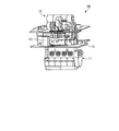
- FIG. 1 is a schematic diagram showing a marine diesel engine provided with the EGR system of the present embodiment.
- FIG. 2 is a schematic block diagram showing the EGR system of the present embodiment.
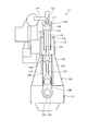
- FIG. 3 is a schematic view showing a schematic configuration of an engine main body of the present embodiment.
- FIG. 4 is a graph showing the relationship between the engine load and the exhaust valve closing timing.
- FIG. 5 is a graph showing another example of the relationship between the engine load and the exhaust valve closing timing.
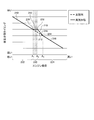
- FIG. 6 is a graph showing the relationship between the rotational speed of the engine body and the exhaust valve closing timing.
- FIG. 1 is a schematic diagram showing a marine diesel engine provided with an EGR system
- FIG. 2 is a schematic configuration diagram showing an EGR system.
- the marine diesel engine 10 of the present embodiment includes an engine body (engine) 11, a supercharger 12, and an EGR system 13.
- the engine body 11 is a propulsion engine (main engine) that drives and rotates a propulsion propeller via a propeller shaft.
- the engine body 11 is a uniflow sweep-type exhaust cross-head diesel engine, and is a two-stroke diesel engine, in which the flow of intake and exhaust in the cylinder is one direction from the lower side to the upper side to eliminate residual exhaust.
- the engine body 11 includes a plurality of cylinders 21 in which the pistons move up and down, a scavenging air trunk 22 in communication with the cylinders 21, and an exhaust manifold 23 in communication with the cylinders 21.
- the scavenging ports 24 are provided between the cylinders 21 and the scavenging trunk 22, and the exhaust flow path 25 is provided between the cylinders 21 and the exhaust manifold 23.
- the engine body 11 has the scavenging air trunk 22 connected to the air supply line G1 and the exhaust manifold 23 connected to the exhaust line G2.
- FIG. 3 is a schematic view showing an engine body.
- FIG. 3 shows a portion of the engine body 11 corresponding to one piston and cylinder 21.
- the engine main body 11 has a base plate 111 located below, a frame 112 provided on the base plate 111, and a cylinder jacket 113 provided on the frame 112.
- the base plate 111, the frame 112 and the cylinder jacket 113 are integrally fastened and fixed by a plurality of tension bolts (tie bolts / connection members) 114 and nuts 115 extending in the vertical direction.
- the cylinder jacket 113 is provided with a cylinder liner 116, and a cylinder cover 117 is provided on the upper end of the cylinder liner 116.
- the cylinder liner 116 and the cylinder cover 117 define a space portion 118, and the piston 119 is provided in the space portion 118 so as to be capable of reciprocating up and down, thereby forming the combustion chamber 120.
- the cylinder cover 117 is provided with an exhaust valve (exhaust gas valve) 121.
- the exhaust valve 121 opens and closes the combustion chamber 120 and the exhaust gas pipe 122.
- the exhaust valve 121 only needs to have a function of opening and closing the combustion chamber 120 and the exhaust gas pipe 122, and is not necessarily provided at the center of the cylinder cover 117.
- combustion is performed by supplying the fuel supplied from the fuel injection pump and the combustion gas compressed by the turbocharger 12 to the combustion chamber 120. Then, the piston 119 moves up and down by the energy generated by this combustion. At this time, when the combustion chamber 120 is opened by the exhaust valve 121, the exhaust gas generated by the combustion is pushed out to the exhaust gas pipe 122, while the combustion gas is introduced from the scavenging port 24 into the combustion chamber 120.
- the exhaust gas pipe 122 is connected to the exhaust manifold 23.
- the piston 119 is connected to the upper end portion of the piston rod 123 and is movably connected to the piston rod 123 in the piston axial direction.
- the base plate 111 is a crankcase and is provided with a bearing 125 for rotatably supporting the crankshaft 124.
- the lower end portion of the connecting rod 127 is rotatably connected to the crankshaft 124 via a crank 126.
- a pair of guide plates 128 extending in the vertical direction is fixed at a predetermined interval, and the crosshead 129 is supported so as to be vertically movable between the pair of guide plates 128.
- the crosshead 129 has a lower half of a crosshead pin provided at a lower end of the piston rod 123 connected to an upper end of a connecting rod 127 so that a crosshead bearing can be freely rotated.
- the piston 119 to which the energy generated in the combustion chamber 120 of the cylinder jacket 113 is transmitted is directed to the installation surface of the engine main body 11 together with the piston rod 123 (downward in the direction of the base plate 111, ie, the piston axial direction Press down to). Then, the piston rod 123 pushes down the crosshead 129 in the piston axial direction to rotate the crankshaft 124 via the connecting rod 127 and the crank 126.
- the engine body 11 is provided with a rotation speed detection unit 62 and a fuel injection amount detection unit 64.
- the rotation speed detection unit 62 detects the rotation speed of the engine main body 11 (the rotation speed of the rotation shaft connected to the propeller shaft).
- the rotation speed detection unit 62 may detect the rotation speed of the rotation shaft inserted in the engine main body 11, or may detect the rotation speed of the propeller shaft.
- the fuel input amount detection unit 64 detects the fuel input amount of the engine body 11.
- the engine control device 26 controls the operation of the engine body 11.
- the engine control device 26 controls the operation of the engine main body 11 based on various input conditions such as a required load and results detected by various sensors such as the rotation speed detection unit 62 and the fuel input amount detection unit 64.
- the engine control unit 26 controls the injection timing of fuel into the cylinder 21, the injection amount, and the opening / closing timing of the exhaust valve 121 to control the amount of injected fuel and the number of revolutions of the engine body 11 and the combustion in the combustion chamber 120.
- the engine control device 26 controls the output of the engine main body 11 by controlling the amount of injected fuel and the number of revolutions.
- the supercharger 12 is configured by connecting a compressor (compressor) 31 and a turbine 32 so as to rotate integrally with a rotating shaft 33.
- the turbine 32 is rotated by the exhaust gas discharged from the exhaust line G2 of the engine body 11, the rotation of the turbine 32 is transmitted by the rotation shaft 33, and the compressor 31 is rotated.
- At least one of the recycle gas is compressed and supplied to the engine body 11 from the air supply line G1 as compressed compressed gas.
- the compressor 31 is connected to a suction line G6 for drawing air from the outside (atmosphere).
- the turbocharger 12 is connected to an exhaust line G3 for discharging the exhaust gas that has rotated the turbine 32, and the exhaust line G3 is connected to a chimney (funnel) not shown. Further, an EGR system 13 is provided between the exhaust line G3 and the air supply line G1.
- the EGR system 13 includes exhaust gas recirculation lines G4, G5, G7, a scrubber 42, a demister unit 14, an EGR blower (blower) 47, and an EGR control device 60.
- the EGR system 13 mixes a part of the exhaust gas discharged from the engine body 11 with air as a recirculation gas, and then compresses the mixture by the turbocharger 12 to recirculate it to the marine diesel engine 10 as a combustion gas. And suppress the generation of NOx by combustion.
- a part of the exhaust gas is extracted from the downstream side of the turbine 32, a part of the exhaust gas may be extracted from the upstream side of the turbine 32.
- the exhaust gas is a gas exhausted from the exhaust line G3 to the outside after being discharged from the engine main body 11 to the exhaust line G2.
- the recycle gas refers to a part of the exhaust gas separated from the exhaust line G3.
- the recirculation gas is returned to the engine body 11 by the exhaust gas recirculation lines G4, G5, G7.
- the exhaust gas recirculation line G4 is connected to the middle of the exhaust line G3.
- the exhaust gas recirculation line G4 is provided with an EGR inlet valve (opening / closing valve) 41A, and the other end is connected to the scrubber 42.
- the EGR inlet valve 41A opens / closes the exhaust gas branched from the exhaust line G3 to the exhaust gas recirculation line G4 by opening / closing the exhaust gas recirculation line G4.
- the EGR inlet valve 41A may be used as a flow rate adjusting valve to adjust the flow rate of the exhaust gas passing through the exhaust gas recirculation line G4.
- the scrubber 42 is a Venturi-type scrubber, and includes a hollow throat 43, a venturi 44 into which exhaust gas is introduced, and an enlarged portion 45 that gradually returns to the original flow velocity.
- the scrubber 42 includes a water injection unit 46 that injects water to the recirculation gas introduced to the venturi unit 44.
- the scrubber 42 is connected to an exhaust gas recirculation line G5 for discharging waste water containing harmful substances and recycled gas from which harmful substances such as SOx and particulates (PM) such as dust are removed.
- a Venturi type is employ
- the marine diesel engine 10 may also be equipped with an exhaust gas cleaning device other than the scrubber 42.
- the exhaust gas recirculation line G5 is provided with a demister unit 14 and an EGR blower 47.
- the demister unit 14 separates the recycled gas and the waste water from which harmful substances have been removed by water injection.
- the demister unit 14 is provided with a drainage circulation line W1 that circulates the drainage to the water injection unit 46 of the scrubber 42.
- the drainage circulation line W1 is provided with a hold tank 49 and a pump 50 for temporarily storing mist (drainage).
- the EGR blower 47 sends the recirculated gas in the scrubber 42 from the exhaust gas recirculation line G5 to the compressor 31 via the demister unit 14.
- the exhaust gas recirculation line G7 has one end connected to the EGR blower 47 and the other end connected to the compressor 31 via a mixer (not shown), and the EGR blower 47 sends the recirculation gas to the compressor 31.
- the exhaust gas recirculation line G7 is provided with an EGR outlet valve (on-off valve or flow control valve) 41B.
- the air from the suction line G6 and the recirculation gas from the exhaust gas recirculation line G7 are mixed in a mixer to generate a combustion gas.
- this mixer may be provided separately from the silencer, or the silencer may be configured to have a function of mixing the recirculation gas and air without separately providing a mixer.
- the supercharger 12 can supply the combustion gas compressed by the compressor 31 from the air supply line G1 to the engine body 11, and an air cooler (cooler) 48 is provided on the air supply line G1.
- the air cooler 48 cools the combustion gas by exchanging heat between the combustion gas compressed by the compressor 31 and having a high temperature and the cooling water.
- an oxygen concentration detection unit 66 is disposed in the air supply line G ⁇ b> 1 or the scavenging trunk 22.
- the oxygen concentration detection unit 66 of the present embodiment is disposed closer to the engine body 11 than the air cooler 48.
- the oxygen concentration detection unit 66 detects the oxygen concentration of the air supplied to the engine body 11, that is, the oxygen concentration of the combustion gas when the EGR system 13 is in operation.
- the EGR control device 60 controls the operation of each part of the EGR system 13.
- the EGR control device 60 acquires load information from the engine control device 26.
- the EGR control device 60 sends information on ON / OFF of the EGR system 13 to the engine control device 26.
- the EGR control device 60 acquires the rotational speed information of the engine body 11 from the rotational speed detection unit 62.
- the EGR control device 60 acquires information on the amount of injected fuel of the engine body 11 from the amount of injected fuel detection unit 64.
- the EGR control device 60 acquires information on the oxygen concentration of the combustion gas supplied from the oxygen concentration detection unit 66 to the engine body 11.
- the EGR control device 60 operates the EGR blower 47 based on the acquired load information of the engine main body 11 and the oxygen concentration of the air supplied to the engine main body 11, and supplies the engine main body 11 from the EGR system 13 again. Control the amount of circulating gas.
- the EGR control device 60 stores the relationship between the load of the engine body 11 and the target value of the oxygen concentration, and calculates the target value of the oxygen concentration according to the load.
- the EGR control device 60 calculates the target value of the oxygen concentration based on the relationship between the load of the engine body 11 and the target value of the oxygen concentration, and the relationship between the calculated target value of the oxygen concentration and the obtained oxygen concentration and the present
- the frequency (operating frequency) of the EGR blower 47 is calculated based on the frequency of the EGR blower 47.
- the EGR control device 60 rotates the EGR blower 47 at the calculated frequency of the EGR blower 47.
- the EGR control device 60 also controls the components other than the EGR blower 47, for example, the opening and closing of the EGR inlet valve 41A and the EGR outlet valve 41B, and the operation of the scrubber 42.
- the operation of the EGR system 13 of the present embodiment will be described.
- the combustion gas is supplied from the scavenging trunk 22 into the cylinder 21, the combustion gas is compressed by the piston, and the fuel for the high temperature combustion gas is compressed. Spontaneous ignition and combustion by injection. Then, the generated combustion gas is discharged from the exhaust manifold 23 to the exhaust line G2 as an exhaust gas.
- the exhaust gas discharged from the engine body 11 is discharged to the exhaust line G3 after rotating the turbine 32 in the turbocharger 12, and when the EGR inlet valve 41A and the EGR outlet valve 41B are closed, the entire amount is the exhaust line It is discharged to the outside from G3.
- a scrubber 42 removes harmful substances from the recycle gas that has flowed to the exhaust gas recirculation line G4. That is, when the recirculating gas passes through the venturi portion 44 at high speed, the scrubber 42 injects water from the water injecting portion 46, thereby cooling the recirculating gas with the water and causing harmful substances to fall together with the water. Remove. Then, the mist (drainage) containing the harmful substance flows into the demister unit 14 together with the recycle gas.
- the recycle gas from which harmful substances have been removed by the scrubber 42 is discharged to the exhaust gas recirculation line G5, and after the mist (drainage) is separated by the demister unit 14, it is sent to the turbocharger 12 by the exhaust gas recirculation line G7. . Then, the recirculated gas is mixed with air taken in from the suction line G6 to become a combustion gas, compressed by the compressor 31 of the supercharger 12, then cooled by the air cooler 48, and from the air supply line G1 to the engine It is supplied to the main body 11.
- FIG. 4 is a graph showing the relationship between the engine load and the exhaust valve closing timing.
- the engine control device 26 changes the exhaust valve closing timing according to the engine load, based on the exhaust valve closing timing pattern which is the relationship between the engine load and the exhaust valve closing timing shown in FIG. 4.
- the exhaust valve closing timing is a timing at which the exhaust valve is closed in the combustion cycle, and can be indicated by the angle of the combustion cycle.
- An exhaust valve closing timing pattern 210 shown by a solid line in FIG. 4 shows the relationship between the engine load and the exhaust valve closing timing of the present embodiment.
- the exhaust valve closing timing patterns 210 and 212 both have a relationship in which the exhaust valve closing timing is delayed as the engine load increases.
- the engine control unit 26 detects an engine load, and controls an exhaust valve closing timing which is a timing for closing the exhaust valve 121 based on the relationship between the detected engine load and the exhaust valve closing timing pattern 210 shown by a solid line in FIG.
- the timing at which the exhaust valve 121 is closed is controlled based on an angle that makes one stroke of the piston of the engine body 11 360 degrees as described above, that is, a crank angle. That is, the engine control device 26 opens the exhaust valve 121 when the crank angle becomes the set angle. When the timing at which the exhaust valve 121 closes is delayed, the exhaust valve 121 is closed at a larger crank angle.
- the rate of change which is the amount of change of the exhaust valve closing timing with respect to the amount of change of the engine load, becomes constant.
- the change rate is fixed, but the change amount may change.
- the exhaust valve closing timing pattern 212 is an ideal line set based on the result of calculating the exhaust valve closing timing at which engine performance such as fuel efficiency becomes high with each engine load without considering the dangerous rotation speed. And the exhaust valve closing timing.
- the ideal line first determines the combustion maximum pressure from the design output of the engine. From this, the combustion pressure of each load is determined, the compression pressure is designed from the combustion pressure, and the planned exhaust valve closing timing is determined to be the compression pressure.
- the exhaust valve closing timing is determined so that parameters such as fuel efficiency and exhaust gas outlet temperature become optimal.
- the exhaust valve closing timing described above is performed for each load, and the optimum exhaust valve closing timing angle is determined for each load.
- the exhaust valve closing timing pattern 212 carries out fine adjustment so as to smoothly connect the timings of the respective loads.
- Exhaust valve closing timing pattern 210 of this embodiment includes a critical rotation range 220 is a range where the engine load is overlapped with the rotational speed region risk (engine load A 1 or the engine load A 2 or less range), than critical rotation range 220 a second range 224 is a range the engine load is small range engine load than the first range 222 and critical rotation range 220 (range of less than the engine load a 1) is larger (in the range of greater than engine load a 2), The change rate of the change amount of the exhaust valve closing timing to the engine load is different.
- the engine load A 2 is a high loading than the engine load A 1.
- the engine load changes depending on the engine speed and the amount of fuel input.
- the dangerous rotation speed range is a load range in which the rotation speed is in the dangerous rotation speed range, taking into consideration the variation range of the fuel input amount changing under various conditions.
- Engine load A 1 is calculated based on the minimum value and the minimum value of the critical speed of rotation of the fuel input amount assumed in critical rotation speed range.
- Engine load A 2 is calculated based on the maximum value and the maximum value of the critical speed of rotation of the fuel input amount assumed in critical rotation speed range.
- the engine load is calculated based on parameters other than the amount of injected fuel and the number of revolutions of the engine body 11.
- Exhaust valve closing timing pattern 210 there is an inflection point 230 which changes the rate of change in the engine load A 1, there is an inflection point 232 where the rate of change varies with engine load A 2, higher than the engine load A 2 change rate is the inflection point 234 which varies the engine load A 3 is.
- Exhaust valve closing timing pattern 210 inflection point 230 (engine load A 1) 240 parts engine load is low segment than next inflection point 230 (engine load A 1) and an inflection point 232 (engine load A 2 ) becomes a line segment 242, and a line segment 244 between an inflection point 232 (engine load A 2 ) and an inflection point 234 (engine load A 3 ) becomes an inflection point 234 (engine load A 3).
- a portion where the engine load is higher than is a line segment 246.
- the line segment 240 and the line segment 246 have the same inclination as the exhaust valve closing timing pattern 212.
- the line segment 242 connects the line segment 240 and the line segment 244, and the rate of change does not change, that is, the exhaust valve closing timing does not change.
- the line segment 244 connects the line segment 242 and the line segment 246, and the change rate is larger than the line segment 242 and the line segment 246.
- the exhaust valve closing timing pattern 210 has a dangerous rotation range 220 including a period during which the engine load (number of rotations of the engine main body 11) passes through the dangerous rotation number range, and a first rotation number lower than the dangerous rotation range 220
- the range 222 there is an inflection point 230 where the rate of change of the change in timing of closing the exhaust valve with respect to the increase in rotational speed changes, and the rate of change of the line segment 242 on the dangerous rotation range 220 side with respect to the inflection point 230 is The change rate of the line segment 240 closer to the first range 222 than the inflection point 230 is smaller.
- the engine control device 26 controls the exhaust valve closing timing based on the exhaust valve closing timing pattern 210 so that the exhaust valve closing timing in the dangerous rotation range 220 is earlier than when operating with the exhaust valve closing timing pattern 212. Become. Thereby, when operating at the dangerous rotation speed, the oxygen excess rate at the time of fuel combustion in the combustion chamber 120 proportional to the increase of the load (rotational speed) of the engine main body 11 as compared with the case other than the dangerous rotation range 220 Can be suppressed. It is possible to suppress a decrease in the oxygen excess rate of the combustion chamber 120 at the same load as in the case where the exhaust valve closing timing pattern 212 is operated.
- the engine control device 26 can increase the amount of oxygen corresponding to the increase of the fuel supplied to the combustion chamber 120 even if the load increases in the dangerous rotation range 220, and can suppress the reduction of the excess air ratio.
- the fuel can be suitably burned. Specifically, in order to pass the load in the dangerous rotation range 220 in a short time, the engine control device 26 increases the fuel input amount, increases the power generated by the combustion, and accelerates the rotation speed in a short time Execute the process By executing this process, the engine control device 26 increases the amount of fuel input.
- the engine control unit 26 controls the exhaust valve closing timing based on the exhaust valve closing timing pattern 210, so that the amount of air corresponding to the increase of the fuel supplied to the combustion chamber 120 even when the fuel input amount increases. Since a large amount of fuel can be held, the amount of oxygen supplied to the combustion chamber 120 can be suppressed from being reduced.
- the amount of oxygen in the fuel decreases, and it is possible to suppress the combustion from becoming unstable, and to suppress the generation of black smoke due to the incomplete combustion.
- the combustion can be stably performed, a desired output can be obtained, and the rotational speed can be suitably increased.
- the oxygen concentration of the air supplied to the combustion chamber 120 decreases, and the risk of combustion instability and black smoke generation increases.
- the exhaust valve closing timing By controlling the exhaust valve closing timing based on the exhaust valve closing timing pattern 210, it is possible to suppress the combustion from becoming unstable and to suppress the generation of black smoke due to the incomplete combustion.
- the combustion can be stably performed, a desired output can be obtained, and the rotational speed can be suitably increased.
- the exhaust valve closing timing pattern 210 makes the amount of oxygen held in the combustion chamber 120 even if the engine load increases in the dangerous rotation range 220, by making the closing timing of the exhaust valve in the dangerous rotation range 220 constant. It can be made the same as or more the conditions under which the engine load is small. Further, by setting the closing timing of the exhaust valve in the dangerous rotation range 220 constant, setting of parameters can be simplified and control can be simplified. Since the control can be simplified, the operation of the engine body 11 can be stabilized.
- the exhaust valve closing timing pattern 210 is an exhaust line calculated to be an ideal line other than the line segment 242 of the dangerous rotation range 220 and the line segment 244 that brings the exhaust valve closing timing pattern 210 closer to the exhaust valve closing timing pattern 212 It is preferable to use a pattern that matches the valve closing timing pattern 212.
- the engine body 11 can be operated more efficiently in the load range other than the dangerous rotation speed range 220.
- the rate of change of the line segment 242 is preferably close to zero. Therefore, when the load of the engine body 11 increases or decreases in the range of the line segment 242, the fluctuation of the exhaust valve closing timing becomes too large, and the operation of the engine body 11 can be prevented from becoming unstable.
- the exhaust valve closing timing pattern 210 associates the load of the engine main body 11 calculated by the parameter including the rotational speed with the timing of closing the exhaust valve, and as the load of the engine main body 11 increases, the exhaust in the combustion cycle The operating efficiency of the engine body 11 can be increased by setting the timing for closing the valve to be delayed.
- the exhaust valve closing timing pattern 210 has a constant exhaust valve closing timing in the dangerous rotation range 220, the present invention is not limited to this.
- the engine control device 26 may switch the applied exhaust valve closing timing pattern 210 between when the load increases (rises) and when the load decreases.
- FIG. 5 is a graph showing another example of the relationship between the engine load and the exhaust valve closing timing.
- the engine control device 26 using the relationship between the engine load and the exhaust valve closing timing shown in FIG. 5 has an exhaust valve closing timing pattern 250 and an exhaust valve closing timing pattern 252.
- the exhaust valve close timing pattern 250 is a relationship between the engine load and the exhaust valve close timing which are applied when the engine load increases.
- the exhaust valve closing timing pattern 252 is the relationship between the engine load and the exhaust valve closing timing that are applied when the engine load decreases.
- Exhaust valve closing timing pattern 250 there is an inflection point 230a which changes the rate of change in the engine load A 1, there is an inflection point 232a which changes the rate of change in the engine load A 2, higher than the engine load A 2 there is an inflection point 234a of the rate of change varies with engine load A 3 is.
- a portion where the engine load is lower than the inflection point 230a (engine load A 1 ) is a line segment 240a, and the inflection point 230a (engine load A 1 ) and the inflection point 232a (engine load A) 2 ) becomes a line segment 242a, and a line segment 244a between an inflection point 232a (engine load A 2 ) and an inflection point 234a (engine load A 3 ) becomes an inflection point 234a (engine load A 3)
- the portion where the engine load is higher than) is the line segment 246a.
- the line segment 240 a and the line segment 246 a have the same inclination as the exhaust valve closing timing pattern calculated based on the ideal line, similar to the exhaust valve closing timing pattern 210.
- the line segment 242a connects the line segment 240a and the line segment 244a, and as the load increases, the exhaust valve closing timing is delayed.
- the change rate of the line segment 242a is smaller than that of the line segment 240a. That is, in the graph in which the vertical axis shown in FIG. 5 is the angle of the exhaust valve closing timing and the horizontal axis is the load of the engine body 11, the inclination of the line segment 242a is smaller than that of the line segment 240a.
- the line segment 244a connects the line segment 242a and the line segment 246a, and the change rate is larger than the line segment 242a and the line segment 246a.
- the exhaust valve closing timing pattern 250 has the dangerous rotation range 220 including the period during which the engine load (rotation speed of the engine body) passes through the dangerous rotation speed region, although the change rate of the line segment 242a is not zero.
- the rate of change in the timing of closing the exhaust valve changes with respect to the increase in the number of rotations.
- the change rate of the line segment 242a on the dangerous rotation range 220 side is smaller than the change rate of the line segment 240a on the first range 222 side than the inflection point 230a.
- the engine control unit 26 changes the change rate of the line segment 242a closer to the dangerous rotation range 220 than the inflection point 230a is closer to the first range 222 than the inflection point 230a.
- the exhaust valve closing timing pattern 250 may cause the operation of the engine main body 11 in the dangerous rotation range 220 to be more unstable than in the exhaust valve closing timing pattern 210, but may increase the operation efficiency. it can.
- Exhaust valve closing timing pattern 252 there is an inflection point at which the rate of change varies with load is small engine load A 4 than the engine load A 1, there is an inflection point at which the rate of change varies with engine load A 1, the engine the rate of change in the load A 2 is an inflection point of change.
- Exhaust valve closing timing pattern 252 the engine load A 4 engine load than lower portion line 240b, and the can next to the line segment 248 between the engine load A 4 and engine load A 1, the engine load A 1 and engine load line segment 244b becomes between the a 2, engine load than the engine load a 2 is higher portion becomes a line segment 246b.
- the line segment 240 b and the line segment 246 b have the same inclination as the exhaust valve closing timing pattern calculated based on the ideal line, similar to the exhaust valve closing timing pattern 250.
- the line segment 248 connects the line segment 240 b and the line segment 244 b, and the change rate is larger than the line segment 240 b and the line segment 244 b.
- the line segment 244b connects the line segment 248 and the line segment 246b, and the exhaust valve closing timing does not change even if the load changes.
- the change rate of the line segment 244 b is zero.
- the engine control device 26 closes the exhaust valve closing timing based on the exhaust valve closing timing pattern 252 Control.
- the engine control device 26 reduces fuel injection in the dangerous rotation range 220, so as shown in the exhaust valve closing timing pattern 252, the dangerous rotation range than the inflection point 230a.
- the change rate of the line segment 244b on the 220 side satisfies the relation smaller than the change rate of the line segment 248 on the first range 222 side than the inflection point 230a, whereby the variation of the exhaust valve closing timing in the dangerous rotation range 220 Can be suppressed.
- the engine control unit 26 sets the rotational speed of the engine main body 11 and the exhaust valve in the dangerous operation range 220 when the rotational speed of the engine main body increases, when the rotational speed of the engine main body decreases,
- the engine main body 11 can be operated more stably by using a different relationship between the closing timing and the closing timing.
- FIG. 6 is a graph showing the relationship between the rotational speed of the engine body and the exhaust valve closing timing.
- FIG. 6 also shows an exhaust valve closing timing pattern 262 which is a relationship between the number of revolutions of the engine main body and the exhaust valve closing timing which are calculated by the ideal line as in FIG. Exhaust valve closing timing pattern shown in FIG.
- the critical rotation range 220a in the range of the rotational speed of the engine body overlaps with speed region risk (engine speed B 1 or the engine rotational speed B 2 following ranges), dangerous range is less the engine speed than the rotation range 220a first range 222a and the range the engine speed is greater than the critical rotation range 220a is (range of less than the engine rotational speed B 1) (engine speed B 2 larger range)
- the change rate of the change amount of the exhaust valve closing timing with respect to the engine speed is different.
- engine speed B 2 is a rotational speed higher than the engine rotational speed B 1.
- Exhaust valve closing timing pattern 260 there is an inflection point 230c of varying the rate of change in engine speed B 1, there is an inflection point 232c of the rate of change varies with engine speed B 2, the engine rotational speed B 2 there is an inflection point 234c which is an engine rotational speed B 3 is also a high value change rate changes.
- a portion where the engine speed is lower than the inflection point 230c (engine speed B 1 ) is the line segment 240c, and the inflection point 230c (engine speed B 1 ) and the inflection point 232c ( A line segment 242c is between the engine speed B 2 ) and a line segment 244c between the inflection point 232c (engine speed B 2 ) and the inflection point 234c (engine speed B 3 ).
- a portion where the engine rotational speed is higher than 234c (engine rotational speed B 3 ) is a line segment 246c.
- the line segment 240 c and the line segment 246 c have the same inclination as the exhaust valve closing timing pattern 262.
- the line segment 242c connects the line segment 240c and the line segment 244c, and the rate of change does not change, that is, the exhaust valve closing timing does not change.
- the line segment 244c connects the line segment 242c and the line segment 246c, and the change rate is larger than the line segment 242c and the line segment 246c. Therefore, the exhaust valve closing timing pattern 260 includes the dangerous rotation range 220a including the time during which the engine rotation speed (the rotation speed of the engine body) passes through the dangerous rotation speed range and the first rotation speed lower than the dangerous rotation range 220a.
- the engine control device 26 controls the exhaust valve closing timing based on the exhaust valve closing timing pattern 260, so that the exhaust valve closing timing in the dangerous rotation range 220a is earlier than when operating with the exhaust valve closing timing pattern 262. Become.
- fuel burns in the combustion chamber 120 in proportion to the increase (increase) of the load (rotational speed) of the engine main body 11 as compared to the case other than the dangerous rotation range 220a. It is possible to suppress the reduction of the oxygen excess rate of That is, the decrease in the amount of oxygen relative to the input fuel can be reduced, and the amount of oxygen in the combustion chamber 120 at the same load can be increased compared to the case where the exhaust valve close timing pattern 262 is operated. Thus, even if control is performed based on the rotational speed of the engine main body 11 instead of the engine load, the engine control device 26 can obtain the same effect as the case of the engine load.
- the engine control device 26 may change the change rate between the dangerous rotation speed region and the other rotation speed regions as well as the exhaust valve opening timing which is the timing for opening the exhaust valve.
Landscapes
- Engineering & Computer Science (AREA)
- Chemical & Material Sciences (AREA)
- Combustion & Propulsion (AREA)
- Mechanical Engineering (AREA)
- General Engineering & Computer Science (AREA)
- Output Control And Ontrol Of Special Type Engine (AREA)
Abstract
危険回転数域での燃焼を安定させ、エンジン本体をより良い条件で運転させることができる舶用ディーゼルエンジンを提供する。排気弁を開閉し、燃焼室内の空気の排気を制御するエンジン本体と、エンジン本体を制御し、エンジン本体の回転数が高くなるにしたがって、燃焼サイクルにおける排気弁を閉じるタイミングが遅くなる排気弁閉タイミングパターンに基づいて、排気弁の動作を制御する制御装置と、を有し、排気弁閉タイミングパターンは、エンジン本体の回転数が、危険回転数域を通過する間を含む危険回転範囲と、危険回転範囲よりも回転数が低い第1範囲とで、回転数の上昇に対する排気弁を閉じるタイミングの変化の変化率が変化する変曲点を有し、変曲点よりも危険回転範囲側の変化率が、変曲点よりも第1範囲側の変化率よりも小さい。
Description
本発明は、舶用ディーゼルエンジンに関するものである。
舶用ディーゼルエンジンは、運転が開始されると回転数を増加させる。エンジンは、回転機械であるため、共振等が生じ、その回転数域での長時間の運転が禁止される危険回転数域(Barred Range、Critical Speed)がある。特許文献1には、エンジンの回転数が危険回転数域となる状態では、燃料を噴射する角度と燃焼領域で燃焼された空気を排気する排気弁を開く角度を調整することが記載されている。具体的には、危険回転数域での排気角度を、危険回転数域よりも低い領域での排気角度よりも小さくすることが記載されている。
また、舶用ディーゼルエンジンでは、危険回転数域で運転する時間を短くするため、危険回転数域では、エンジンの回転数を短時間に増加させるための制御を実行する場合がある。このように、エンジンの回転数を増加させる制御を実行すると、エンジンでの燃料と空気とのバランスが崩れ、燃料の燃焼が不十分となり、回転数の増加速度が低下したり、黒煙が発生したりする恐れがある。
本発明は上述した課題を解決するものであり、危険回転数域での燃焼を安定させ、エンジン本体をより良い条件で運転させることができる舶用ディーゼルエンジンを提供することを目的とする。
上記の目的を達成するための本発明は、舶用ディーゼルエンジンであって、排気弁を開閉し、燃焼室内からの排気を制御するエンジン本体と、前記エンジン本体を制御し、前記エンジン本体の負荷または回転数が高くなるにしたがって、燃焼サイクルにおける前記排気弁を閉じるタイミングが遅くなる排気弁閉タイミングパターンに基づいて、前記排気弁の動作を制御する制御装置と、を有し、前記排気弁閉タイミングパターンは、前記エンジン本体の負荷または回転数が、危険回転数域を通過する間を含む危険回転範囲と、前記危険回転範囲よりも負荷または回転数が低い第1範囲とで、前記負荷または前記回転数の上昇に対する前記排気弁を閉じるタイミングの変化の変化率が変化する変曲点を有し、前記変曲点よりも前記危険回転範囲側における変化率が、前記変曲点よりも前記第1範囲側における変化率よりも小さいことを特徴とする。
舶用ディーゼルエンジンは、エンジン本体の回転数が高くなるにしたがって、燃焼サイクルにおける排気弁を閉じるタイミングが遅くなる排気弁閉タイミングパターンを設定し、さらに、排気弁閉タイミングパターンの変曲点よりも危険回転範囲側の変化率を、変曲点よりも第1範囲側の変化率よりも小さくする。これにより、舶用ディーゼルエンジンは、エンジン本体が危険回転数で回転している状態の際に、燃焼室により多くの空気が保持された状態で燃焼を行うことができる。これにより、危険回転数域での燃焼を安定させることができる。これにより、危険回転数域でエンジンの回転数が増加する速度をより高くし、かつ、燃焼時の黒煙の発生を抑制することができる。
また、前記排気弁閉タイミングパターンは、回転数を含むパラメータで算出される前記エンジン本体の負荷と、前記排気弁を閉じるタイミングと、が対応付けられ、前記エンジンの負荷が高くなるにしたがって、燃焼サイクルにおける前記排気弁を閉じるタイミングが遅くなることが好ましい。
また、前記排気弁閉タイミングパターンは、前記危険回転範囲で、前記排気弁の閉じるタイミングが一定であることが好ましい。
また、前記排気弁閉タイミングパターンは、前記エンジン本体の回転数が増加する場合と、前記エンジン本体の回転数が減少する場合と、で前記危険運転範囲の前記エンジン本体の負荷または回転数と前記排気弁を閉じるタイミングと、が異なることが好ましい。
本発明によれば、危険回転数域での運転時でも燃焼室での空気量を多くすることができ、危険回転数域での燃焼を安定させることができる。これにより、危険回転数域でエンジンの回転数が増加する速度をより高くし、かつ、燃焼時の黒煙の発生を抑制することができる。
以下に添付図面を参照して、本発明の好適な実施形態を詳細に説明する。なお、この実施形態により本発明が限定されるものではなく、また、実施形態が複数ある場合には、各実施形態を組み合わせて構成するものも含むものである。
図1は、EGRシステムを備えた舶用ディーゼルエンジンを表す概略図、図2は、EGRシステムを表す概略構成図である。
図1に示すように、本実施形態の舶用ディーゼルエンジン10は、エンジン本体(エンジン)11と、過給機12と、EGRシステム13を備えている。
図2に示すように、エンジン本体11は、図示しないが、プロペラ軸を介して推進用プロペラを駆動回転させる推進用の機関(主機関)である。このエンジン本体11は、ユニフロー掃排気式のクロスヘッド式ディーゼルエンジンであって、2ストロークディーゼルエンジンであり、シリンダ内の吸排気の流れを下方から上方への一方向とし、排気の残留を無くすようにしたものである。エンジン本体11は、ピストンが上下移動する複数のシリンダ21と、各シリンダ21に連通する掃気トランク22と、各シリンダ21に連通する排気マニホールド23とを備えている。そして、各シリンダ21と掃気トランク22との間に掃気ポート24が設けられ、各シリンダ21と排気マニホールド23との間に排気流路25が設けられている。そして、エンジン本体11は、掃気トランク22に給気ラインG1が連結され、排気マニホールド23に排気ラインG2が連結されている。
図3は、エンジン本体を表す概略図である。図3は、エンジン本体11のうち1つのピストン及びシリンダ21に対応する部分を示している。エンジン本体11は、下方に位置する台板111と、台板111上に設けられる架構112と、架構112上に設けられるシリンダジャケット113とを有している。この台板111と架構112とシリンダジャケット113は、上下方向に延在する複数のテンションボルト(タイボルト/連結部材)114及びナット115により一体に締結されて固定されている。
シリンダジャケット113は、シリンダライナ116が設けられており、このシリンダライナ116の上端にシリンダカバー117が設けられている。シリンダライナ116とシリンダカバー117は、空間部118を区画しており、この空間部118内にピストン119が上下に往復動自在に設けられることで、燃焼室120が形成される。また、シリンダカバー117は、排気弁(排ガス弁)121が設けられている。この排気弁121は、燃焼室120と排ガス管122とを開閉するものである。なお、排気弁121は、燃焼室120と排ガス管122とを開閉する機能を有していればよく、必ずしもシリンダカバー117の中央部に設ける必要はない。
そのため、燃焼室120に対して、燃料噴射ポンプから供給された燃料と、過給機12により圧縮された燃焼用ガスが供給されることで燃焼する。そして、この燃焼で発生したエネルギによりピストン119が上下動する。また、このとき、排気弁121により燃焼室120が開放されると、燃焼によって生じた排ガスが排ガス管122に押し出される一方、掃気ポート24から燃焼用ガスが燃焼室120に導入される。排ガス管122は、排気マニホールド23と接続している。
ピストン119は、ピストン棒123の上端部に接続されるとともに、ピストン棒123とともにピストン軸方向に移動可能に連結されている。台板111は、クランクケースとされており、クランクシャフト124を回転自在に支持する軸受125が設けられている。また、クランクシャフト124は、クランク126を介して連接棒127の下端部が回動自在に連結されている。架構112は、上下方向に延在する一対のガイド板128が所定間隔を空けて固定されており、一対のガイド板128の間にクロスヘッド129が上下に移動自在に支持されている。クロスヘッド129は、ピストン棒123の下端部に設けられたクロスヘッドピンの下半部を連接棒127の上端部に接続されるクロスヘッド軸受が回動自在となるように連結されている。
そのため、シリンダジャケット113の燃焼室120で発生したエネルギが伝達されたピストン119は、ピストン棒123と共に、エンジン本体11の設置面に向かって(台板111側の方向、即ち、ピストン軸方向における下向き)に押し下げる。すると、ピストン棒123は、クロスヘッド129をピストン軸方向に押し下げ、連接棒127及びクランク126を介してクランクシャフト124を回転させる。
エンジン本体11には、回転数検出部62と、燃料投入量検出部64とが配置されている。回転数検出部62は、エンジン本体11の回転数(プロペラ軸と接続された回転軸の回転数)を検出する。回転数検出部62は、エンジン本体11に挿入された回転軸の回転数を検出してもよいが、プロペラ軸の回転数を検出してもよい。燃料投入量検出部64は、エンジン本体11の燃料投入量を検出する。
エンジン制御装置26は、エンジン本体11の運転を制御する。エンジン制御装置26は、要求負荷等の各種入力条件及び回転数検出部62と燃料投入量検出部64等の各種センサで検出した結果とに基づいて、エンジン本体11の運転を制御する。エンジン制御装置26は、シリンダ21への燃料の噴射タイミングや、噴射量、排気弁121の開閉タイミングを制御して、エンジン本体11の燃料投入量や回転数、燃焼室120での燃焼を制御する。エンジン制御装置26は、燃料投入量や回転数を制御することで、エンジン本体11の出力を制御する。
過給機12は、コンプレッサ(圧縮機)31とタービン32とが回転軸33により一体に回転するように連結されて構成されている。この過給機12は、エンジン本体11の排気ラインG2から排出された排ガスによりタービン32が回転し、タービン32の回転が回転軸33により伝達されてコンプレッサ31が回転し、このコンプレッサ31が空気及び再循環ガスの少なくとも一方を圧縮し、圧縮した圧縮気体として給気ラインG1からエンジン本体11に供給する。コンプレッサ31は外部(大気)から空気を吸入する吸入ラインG6に接続されている。
過給機12は、タービン32を回転した排ガスを排出する排気ラインG3が連結されており、この排気ラインG3は、図示しない煙突(ファンネル)に連結されている。また、排気ラインG3から給気ラインG1までの間にEGRシステム13が設けられている。
EGRシステム13は、排ガス再循環ラインG4、G5、G7と、スクラバ42と、デミスタユニット14と、EGRブロワ(送風機)47と、EGR制御装置60と、を備えている。このEGRシステム13は、エンジン本体11から排出された排ガスの一部を再循環ガスとして空気と混合した後、過給機12により圧縮して燃焼用ガスとして舶用ディーゼルエンジン10に再循環させることで、燃焼によるNOxの生成を抑制するものである。なお、ここでは、タービン32の下流側から排ガスの一部を抽気したが、タービン32の上流側から排ガスの一部を抽気してもよい。
なお、以下の説明にて、排ガスとは、エンジン本体11から排気ラインG2に排出された後、排気ラインG3から外部に排出されるガスである。再循環ガスとは、排気ラインG3から分離された一部の排ガスを指す。再循環ガスは排ガス再循環ラインG4、G5、G7によりエンジン本体11に戻されるものである。
排ガス再循環ラインG4は、一端が排気ラインG3の中途部に接続されている。排ガス再循環ラインG4は、EGR入口バルブ(開閉弁)41Aが設けられており、他端がスクラバ42に接続されている。EGR入口バルブ41Aは、排ガス再循環ラインG4を開閉することで、排気ラインG3から排ガス再循環ラインG4に分流する排ガスをON/OFFする。なお、EGR入口バルブ41Aを流量調整弁とし、排ガス再循環ラインG4を通過する排ガスの流量を調整するようにしてもよい。
スクラバ42は、ベンチュリ式のスクラバであり、中空形状をなすスロート部43と、排ガスが導入されるベンチュリ部44と、元の流速に段階的に戻す拡大部45とを備えている。スクラバ42は、ベンチュリ部44に導入された再循環ガスに対して水を噴射する水噴射部46を備えている。スクラバ42は、SOxや煤塵などの微粒子(PM)といった有害物質が除去された再循環ガス及び有害物質を含む排水を排出する排ガス再循環ラインG5が連結されている。なお、本実施形態では、スクラバとしてベンチュリ式を採用しているが、この構成に限定されるものではない。また、舶用ディーゼルエンジン10は、スクラバ42以外の排ガス洗浄装置を備えていてもよい。
排ガス再循環ラインG5は、デミスタユニット14とEGRブロワ47が設けられている。
デミスタユニット14は、水噴射により有害物質が除去された再循環ガスと排水を分離するものである。デミスタユニット14は、排水をスクラバ42の水噴射部46に循環する排水循環ラインW1が設けられている。そして、この排水循環ラインW1は、ミスト(排水)を一時的に貯留するホールドタンク49とポンプ50が設けられている。
EGRブロワ47は、スクラバ42内の再循環ガスを排ガス再循環ラインG5からデミスタユニット14を経由して、コンプレッサ31に送るものである。
排ガス再循環ラインG7は、一端がEGRブロワ47に接続されると共に、他端が混合器(図示略)を介してコンプレッサ31に接続されており、EGRブロワ47により再循環ガスがコンプレッサ31に送られる。排ガス再循環ラインG7は、EGR出口バルブ(開閉弁または流量調整弁)41Bが設けられている。吸入ラインG6からの空気と、排ガス再循環ラインG7からの再循環ガスは、混合器で混合されることで燃焼用ガスが生成される。なお、この混合器は、サイレンサと別に設けられてもよいし、混合器を別途設けることなく、再循環ガスと空気を混合する機能を付加するようにサイレンサを構成してもよい。そして、過給機12は、コンプレッサ31が圧縮した燃焼用ガスを給気ラインG1からエンジン本体11に供給可能であり、給気ラインG1にエアクーラ(冷却器)48が設けられている。このエアクーラ48は、コンプレッサ31により圧縮されて高温となった燃焼用ガスと冷却水とを熱交換することで、燃焼用ガスを冷却するものである。また、EGRシステム13は、給気ラインG1または掃気トランク22に酸素濃度検出部66が配置されている。本実施形態の酸素濃度検出部66は、エアクーラ48よりもエンジン本体11側に配置されている。酸素濃度検出部66は、エンジン本体11に供給される空気の酸素濃度、つまりEGRシステム13が稼働している場合は、燃焼用ガスの酸素濃度を検出する。
EGR制御装置60は、EGRシステム13の各部の動作を制御する。EGR制御装置60は、エンジン制御装置26から負荷情報を取得する。EGR制御装置60は、エンジン制御装置26にEGRシステム13のON、OFFの情報を送る。EGR制御装置60は、回転数検出部62からエンジン本体11の回転数情報を取得する。EGR制御装置60は、燃料投入量検出部64からエンジン本体11の燃料投入量の情報を取得する。EGR制御装置60は、酸素濃度検出部66からエンジン本体11に供給される燃焼用ガスの酸素濃度の情報を取得する。EGR制御装置60は、取得したエンジン本体11の負荷情報と、エンジン本体11に供給される空気の酸素濃度とに基づいて、EGRブロワ47の運転状態、EGRシステム13からエンジン本体11に供給する再循環ガスの量を制御する。EGR制御装置60は、エンジン本体11の負荷と酸素濃度の目標値との関係を記憶しており、負荷に応じて酸素濃度の目標値を算出する。EGR制御装置60は、エンジン本体11の負荷と酸素濃度の目標値との関係とに基づいて酸素濃度の目標値を算出し、算出した酸素濃度の目標値と取得した酸素濃度との関係と現在のEGRブロワ47の周波数とに基づいて、EGRブロワ47の周波数(運転周波数)を算出する。EGR制御装置60は、算出したEGRブロワ47の周波数でEGRブロワ47を回転させる。EGR制御装置60は、EGRブロワ47以外の各部、例えば、EGR入口バルブ41A、EGR出口バルブ41Bの開閉や、スクラバ42の運転も制御する。
以下、本実施形態のEGRシステム13の作用を説明する。図2に示すように、エンジン本体11は、掃気トランク22からシリンダ21内に燃焼用ガスが供給されると、ピストンによってこの燃焼用ガスが圧縮され、この高温の燃焼用ガスに対して燃料を噴射することで自然着火し、燃焼する。そして、発生した燃焼ガスは、排ガスとして排気マニホールド23から排気ラインG2に排出される。エンジン本体11から排出された排ガスは、過給機12におけるタービン32を回転した後、排気ラインG3に排出され、EGR入口バルブ41A及びEGR出口バルブ41Bが閉止しているときは、全量が排気ラインG3から外部に排出される。
一方、EGR入口バルブ41A及びEGR出口バルブ41Bが開放しているとき、排ガスは、その一部が再循環ガスとして排気ラインG3から排ガス再循環ラインG4に流れる。排ガス再循環ラインG4に流れた再循環ガスは、スクラバ42により、有害物質が除去される。即ち、スクラバ42は、再循環ガスがベンチュリ部44を高速で通過するとき、水噴射部46から水を噴射することで、この水により再循環ガスを冷却すると共に、有害物質を水と共に落下させて除去する。そして、有害物質を含むミスト(排水)は、再循環ガスと共にデミスタユニット14に流入する。
スクラバ42により有害物質が除去された再循環ガスは、排ガス再循環ラインG5に排出され、デミスタユニット14によりミスト(排水)が分離された後、排ガス再循環ラインG7により過給機12に送られる。そして、この再循環ガスは、吸入ラインG6から吸入された空気と混合されて燃焼用ガスとなり、過給機12のコンプレッサ31で圧縮された後、エアクーラ48で冷却され、給気ラインG1からエンジン本体11に供給される。
次に、図4を用いて、舶用ディーゼルエンジン10のエンジン制御装置26で実行するエンジン本体11の制御について説明する。図4は、エンジン負荷と排気弁閉タイミングとの関係を示すグラフである。エンジン制御装置26は、図4に示すエンジン負荷と排気弁閉タイミングとの関係である排気弁閉タイミングパターンに基づいて、エンジン負荷に応じて、排気弁閉タイミングを変化させる。排気弁閉タイミングは、燃焼サイクルにおいて排気弁を閉じるタイミングであり、燃焼サイクルの角度で示すことができる。図4の実線で示す排気弁閉タイミングパターン210は、本実施形態のエンジン負荷と排気弁閉タイミングとの関係を示している。図4の点線で示す排気弁閉タイミングパターン212は、比較例のエンジン負荷と排気弁閉タイミングとの関係を示している。排気弁閉タイミングパターン210、212は、いずれもエンジン負荷が増加すると、排気弁閉タイミングが遅くなる関係となる。エンジン制御装置26は、エンジン負荷を検出し、検出したエンジン負荷と図4の実線で示す排気弁閉タイミングパターン210の関係に基づいて排気弁121を閉じるタイミングである排気弁閉タイミングを制御する。
排気弁121を閉じるタイミングは、上述したようにエンジン本体11のピストンの1ストロークを360度とした角度、つまりクランク角度に基づいて制御する。つまり、エンジン制御装置26は、クランク角度が設定された角度となった場合に排気弁121を開く。排気弁121が閉じるタイミングが遅くなると、クランク角度がより大きい角度で排気弁121が閉じられる。
比較例の排気弁閉タイミングパターン212は、エンジン負荷の変化量に対する排気弁閉タイミングの変化量である変化率が一定となる。なお、図4の比較例では、変化率を一定としたが変化量が変化してもよい。ここで、排気弁閉タイミングパターン212は、危険回転数を考慮せずに、各エンジン負荷で燃費等のエンジン性能が高くなる排気弁閉タイミングを算出して、その結果に基づいて設定した理想線となるエンジン負荷と排気弁閉タイミングとの関係である。ここで、理想線は、まず、エンジンの設計出力から燃焼時最大圧力を決定する。そこから各負荷の燃焼時圧力を決定し、その燃焼時圧力から圧縮圧力を設計し、その圧縮圧力になるように計画の排気弁の閉タイミングを決定する。その後、試運転によって計画の排気弁閉タイミング付近で、変更・調整し、燃費及び排ガス出口温度等のパラメータが最適になるように排気弁閉タイミングを決定する。各負荷で上述した排気弁閉タイミングを実施し、最適な排気弁閉タイミングの角度を各負荷で決定する。排気弁閉タイミングパターン212は、この時各負荷のタイミングを滑らかにつながるように微調整を実施し、決定する。
本実施形態の排気弁閉タイミングパターン210は、エンジン負荷が危険回転数域と重なる範囲(エンジン負荷A1以上エンジン負荷A2以下の範囲)である危険回転範囲220と、危険回転範囲220よりもエンジン負荷が小さい範囲(エンジン負荷A1未満の範囲)である第1範囲222及び危険回転範囲220よりもエンジン負荷が大きい範囲(エンジン負荷A2より大きいの範囲)である第2範囲224と、でエンジン負荷に対する排気弁閉タイミングの変化量の変化率が異なる。ここで、エンジン負荷A2は、エンジン負荷A1よりも高い負荷である。また、エンジン負荷は、エンジン回転数と燃料投入量等によって変化する。危険回転数域は、各種条件で変化する燃料投入量の変化幅を考慮して、回転数が危険回転数域となる負荷の範囲である。エンジン負荷A1は、危険回転数域で想定される燃料投入量の最小値と危険回転数の最小値とに基づいて算出される。エンジン負荷A2は、危険回転数域で想定される燃料投入量の最大値と危険回転数の最大値とに基づいて算出される。なお、エンジン負荷は、燃料投入量以外のパラメータとエンジン本体11の回転数に基づいて算出される。
排気弁閉タイミングパターン210は、エンジン負荷A1で変化率が変化する変曲点230があり、エンジン負荷A2で変化率が変化する変曲点232があり、エンジン負荷A2よりも高い値であるエンジン負荷A3で変化率が変化する変曲点234がある。排気弁閉タイミングパターン210は、変曲点230(エンジン負荷A1)よりもエンジン負荷が低い部分が線分240となり、変曲点230(エンジン負荷A1)と変曲点232(エンジン負荷A2)との間が線分242となり、変曲点232(エンジン負荷A2)と変曲点234(エンジン負荷A3)との間が線分244となり、変曲点234(エンジン負荷A3)よりもエンジン負荷が高い部分が線分246となる。線分240と線分246は、排気弁閉タイミングパターン212と同じ傾きとなる。線分242は、線分240と線分244を結んでおり、変化率が変化しない、つまり、排気弁閉タイミングが変化しない。線分244は、線分242と線分246とを結んでおり、変化率が線分242及び線分246よりも大きい。したがって、排気弁閉タイミングパターン210は、エンジン負荷(エンジン本体11の回転数)が、危険回転数域を通過する間を含む危険回転範囲220と、危険回転範囲220よりも回転数が低い第1範囲222とで、回転数の上昇に対する排気弁を閉じるタイミングの変化の変化率が変化する変曲点230を有し、変曲点230よりも危険回転範囲220側の線分242の変化率が、変曲点230よりも第1範囲222側の線分240の変化率よりも小さい。
エンジン制御装置26は、排気弁閉タイミングパターン210に基づいて、排気弁閉タイミングを制御することで、排気弁閉タイミングパターン212で運転した場合よりも危険回転範囲220での排気弁閉タイミングが早くなる。これにより、危険回転数で運転されている場合、危険回転範囲220以外の場合に比べて、エンジン本体11の負荷(回転数)の上昇に比例した燃焼室120での燃料燃焼時の酸素過剰率の低下を抑制することができる。排気弁閉タイミングパターン212で運転した場合と比べ同じ負荷での燃焼室120の酸素過剰率の低下を抑制することができる。
エンジン制御装置26は、危険回転範囲220で負荷が上昇しても燃焼室120に供給する燃料の増加に対応して酸素の量を増加させることができ、空気過剰率の低下を抑制できることで、燃料の燃焼を好適に行うことができる。具体的には、エンジン制御装置26は、危険回転範囲220の負荷を短時間で通過するために、燃料投入量を増加させ、燃焼で生じる出力を増加させ、回転数を短時間に増速させる処理を実行する。エンジン制御装置26は、この処理を実行することで燃料投入量が多くなる。ここで、ディーゼルエンジンシステム10は、エンジン負荷が上昇すると過給機12の回転数が上昇するため、単位時間当たりに供給される空気量は増加するが、危険回転範囲220では、燃料の増加の上昇に対して、過給機12の回転数の上昇が少なくなりやすく、排気弁閉タイミングが他の領域と同様に変化すると、燃料に対する酸素量が少なくなる。エンジン制御装置26は、排気弁閉タイミングパターン210に基づいて、排気弁閉タイミングを制御することで、燃料投入量が増加した場合でも燃焼室120に供給する燃料の増加に対応して空気量を多く保持することができるため、燃焼室120に供給する燃料に対して酸素が少なくなることを抑制できる。これにより、燃料に対して酸素が少なくなり、燃焼が不安定になることを抑制でき、不完全燃焼で黒煙が発生することを抑制できる。また、燃焼が安定して実行できることで、所望の出力を得ることができ、回転数を好適に上昇させることができる。特に、本実施形態の舶用ディーセルエンジン10は、EGRシステム13を稼動させることで、燃焼室120に供給される空気の酸素濃度が低くなり、燃焼の不安定性や黒煙発生のリスクが大きくなるが、排気弁閉タイミングパターン210に基づいて、排気弁閉タイミングを制御することで、燃焼が不安定になることを抑制でき、不完全燃焼で黒煙が発生することを抑制できる。また、燃焼が安定して実行できることで、所望の出力を得ることができ、回転数を好適に上昇させることができる。
排気弁閉タイミングパターン210は、危険回転範囲220での排気弁の閉タイミングを一定とすることで、危険回転範囲220においてエンジン負荷が上昇しても燃焼室120内に保持する酸素の量を、エンジン負荷が小さい条件と同様以上の量とすることができる。また、危険回転範囲220での排気弁の閉タイミングを一定とすることで、パラメータの設定を簡単にすることができ、制御を簡単にすることができる。制御を簡単にできることでエンジン本体11の運転を安定させることができる。
また、排気弁閉タイミングパターン210は、危険回転範囲220の線分242と、排気弁閉タイミングパターン210を排気弁閉タイミングパターン212に近づける線分244以外は、理想線となるように算出した排気弁閉タイミングパターン212と一致するパターンとすることが好ましい。これにより、危険回転数範囲220以外の負荷の範囲で、エンジン本体11をより効率よく運転することができる。
ここで、排気弁閉タイミングパターン210は、線分242の変化率はゼロに近いことが好ましい。これにより、エンジン本体11の負荷が線分242の範囲で増減した場合に、排気弁閉タイミングの変動が大きくなりすぎ、エンジン本体11の運転が不安定になることを抑制できる。
また、排気弁閉タイミングパターン210は、回転数を含むパラメータで算出されるエンジン本体11の負荷と排気弁を閉じるタイミングとを対応付け、エンジン本体11の負荷が高くなるにしたがって、燃焼サイクルにおける排気弁を閉じるタイミングが遅くなる関係とすることで、エンジン本体11の運転効率を高くすることができる。
ここで、排気弁閉タイミングパターン210は、危険回転範囲220で排気弁閉タイミングを一定としたが本発明はこれに限定されない。また、エンジン制御装置26は、負荷が増加(上昇)する場合と、減少する場合とで、適用する排気弁閉タイミングパターン210を切り換えてもよい。
図5は、エンジン負荷と排気弁閉タイミングとの関係の他の例を示すグラフである。以下、図5を用いて、排気弁閉タイミングパターンの他の例を説明する。図5のエンジン負荷と排気弁閉タイミングとの関係を用いるエンジン制御装置26は、排気弁閉タイミングパターン250と排気弁閉タイミングパターン252と、を有する。排気弁閉タイミングパターン250は、エンジン負荷が増加する場合に適用されるエンジン負荷と排気弁閉タイミングとの関係である。排気弁閉タイミングパターン252は、エンジン負荷が減少する場合に適用されるエンジン負荷と排気弁閉タイミングとの関係である。
排気弁閉タイミングパターン250は、エンジン負荷A1で変化率が変化する変曲点230aがあり、エンジン負荷A2で変化率が変化する変曲点232aがあり、エンジン負荷A2よりも高い値であるエンジン負荷A3で変化率が変化する変曲点234aがある。排気弁閉タイミングパターン250は、変曲点230a(エンジン負荷A1)よりもエンジン負荷が低い部分が線分240aとなり、変曲点230a(エンジン負荷A1)と変曲点232a(エンジン負荷A2)との間が線分242aとなり、変曲点232a(エンジン負荷A2)と変曲点234a(エンジン負荷A3)との間が線分244aとなり、変曲点234a(エンジン負荷A3)よりもエンジン負荷が高い部分が線分246aとなる。線分240aと線分246aは、排気弁閉タイミングパターン210と同様で理想線に基づいて算出される排気弁閉タイミングパターンと同じ傾きとなる。線分242aは、線分240aと線分244aを結んでおり、負荷が増加するにしたがって排気弁閉タイミングが遅くなる。線分242aは、線分240aに比べて変化率が小さくなる。つまり線分242aは、図5に示す縦軸を排気弁閉タイミングの角度とし、横軸をエンジン本体11の負荷としたグラフにおいて、線分240aよりも傾きが小さくなる。線分244aは、線分242aと線分246aとを結んでおり、変化率が線分242a及び線分246aよりも大きい。
このように、排気弁閉タイミングパターン250は、線分242aの変化率が0ではないが、エンジン負荷(エンジン本体の回転数)が、危険回転数域を通過する間を含む危険回転範囲220と、危険回転範囲220よりも回転数が低い第1範囲222とで、回転数の上昇に対する排気弁を閉じるタイミングの変化の変化率が変化する変曲点230aを有し、変曲点230aよりも危険回転範囲220側の線分242aの変化率が、変曲点230aよりも第1範囲222側の線分240aの変化率よりも小さい関係を満たす。エンジン制御装置26は、線分242aの変化率が0ではない場合も変曲点230aよりも危険回転範囲220側の線分242aの変化率が、変曲点230aよりも第1範囲222側の線分240aの変化率よりも小さい関係を満たすことで、上記と同様の効果を得ることができる。また、排気弁閉タイミングパターン250は、危険回転範囲220でのエンジン本体11の運転が、排気弁閉タイミングパターン210の場合よりも不安定になる恐れがあるが、運転の効率を上昇させることができる。
排気弁閉タイミングパターン252は、エンジン負荷A1よりも負荷が小さいエンジン負荷A4で変化率が変化する変曲点があり、エンジン負荷A1で変化率が変化する変曲点があり、エンジン負荷A2で変化率が変化する変曲点がある。排気弁閉タイミングパターン252は、エンジン負荷A4よりもエンジン負荷が低い部分が線分240bとなり、エンジン負荷A4とエンジン負荷A1との間が線分248となり、エンジン負荷A1とエンジン負荷A2との間が線分244bとなり、エンジン負荷A2よりもエンジン負荷が高い部分が線分246bとなる。線分240bと線分246bは、排気弁閉タイミングパターン250と同様で理想線に基づいて算出される排気弁閉タイミングパターンと同じ傾きとなる。線分248は、線分240bと線分244bを結んでおり、変化率が線分240b及び線分244bよりも大きい。線分244bは、線分248と線分246bを結んでおり、負荷が変化しても排気弁閉タイミングが変化しない。線分244bは、変化率が0となる。
エンジン制御装置26は、エンジン本体11の負荷が減少する場合、例えば、所定の船速で航行している状態からエンジン本体11を停止させる場合、排気弁閉タイミングパターン252に基づいて排気弁閉タイミングを制御する。エンジン制御装置26は、エンジン本体11の負荷が減少する場合、危険回転範囲220で、燃料の投入が少なくなるため、排気弁閉タイミングパターン252に示すように、変曲点230aよりも危険回転範囲220側の線分244bの変化率が、変曲点230aよりも第1範囲222側の線分248の変化率よりも小さい関係を満たすことで、危険回転範囲220での排気弁閉タイミングの変動を抑制することができる。これにより、危険回転範囲220において酸素過剰率が急激に変化することを抑制でき、燃焼を安定させることができる。
エンジン制御装置26は、排気弁閉タイミングパターンとして、エンジン本体の回転数が増加する場合と、エンジン本体の回転数が減少する場合と、危険運転範囲220のエンジン本体11の回転数と排気弁を閉じるタイミングと、が異なる関係を用いることで、エンジン本体11をより安定して運転させることができる。
また、上記実施形態は、エンジン負荷に基づいて排気弁閉タイミングを制御したが、これに限定されない。エンジン制御装置26は、エンジン本体11の回転数に基づいて、排気弁閉タイミングを制御してもよい。図6は、エンジン本体の回転数と排気弁閉タイミングとの関係を示すグラフである。図6は、図4と同様に理想線で算出したエンジン本体の回転数と排気弁閉タイミングとの関係である排気弁閉タイミングパターン262も示す。図6に示す排気弁閉タイミングパターン260は、エンジン本体の回転数が危険回転数域と重なる範囲(エンジン回転数B1以上エンジン回転数B2以下の範囲)である危険回転範囲220aと、危険回転範囲220aよりもエンジン回転数が小さい範囲(エンジン回転数B1未満の範囲)である第1範囲222a及び危険回転範囲220aよりもエンジン回転数が大きい範囲(エンジン回転数B2より大きい範囲)である第2範囲224aと、でエンジン回転数に対する排気弁閉タイミングの変化量の変化率が異なる。ここで、エンジン回転数B2は、エンジン回転数B1よりも高い回転数である。
排気弁閉タイミングパターン260は、エンジン回転数B1で変化率が変化する変曲点230cがあり、エンジン回転数B2で変化率が変化する変曲点232cがあり、エンジン回転数B2よりも高い値であるエンジン回転数B3で変化率が変化する変曲点234cがある。排気弁閉タイミングパターン260は、変曲点230c(エンジン回転数B1)よりもエンジン回転数が低い部分が線分240cとなり、変曲点230c(エンジン回転数B1)と変曲点232c(エンジン回転数B2)との間が線分242cとなり、変曲点232c(エンジン回転数B2)と変曲点234c(エンジン回転数B3)との間が線分244cとなり、変曲点234c(エンジン回転数B3)よりもエンジン回転数が高い部分が線分246cとなる。線分240cと線分246cは、排気弁閉タイミングパターン262と同じ傾きとなる。線分242cは、線分240cと線分244cを結んでおり、変化率が変化しない、つまり、排気弁閉タイミングが変化しない。線分244cは、線分242cと線分246cとを結んでおり、変化率が線分242c及び線分246cよりも大きい。したがって、排気弁閉タイミングパターン260は、エンジン回転数(エンジン本体の回転数)が、危険回転数域を通過する間を含む危険回転範囲220aと、危険回転範囲220aよりも回転数が低い第1範囲222aとで、回転数の上昇に対する排気弁を閉じるタイミングの変化の変化率が変化する変曲点230cを有し、変曲点230cよりも危険回転範囲220a側の線分242cの変化率が、変曲点230cよりも第1範囲222a側の線分240cの変化率よりも小さい。
エンジン制御装置26は、排気弁閉タイミングパターン260に基づいて、排気弁閉タイミングを制御することで、排気弁閉タイミングパターン262で運転した場合よりも危険回転範囲220aでの排気弁閉タイミングが早くなる。これにより、危険回転数で運転されている場合、危険回転範囲220a以外の場合に比べて、エンジン本体11の負荷(回転数)の上昇(増加)に比例して燃焼室120での燃料燃焼時の酸素過剰率が低下することを抑制できる。つまり、投入される燃料に対する酸素の量の減少を少なくすることができ、排気弁閉タイミングパターン262で運転した場合と比べ同じ負荷での燃焼室120の酸素の量を多くすることができる。このように、エンジン制御装置26は、エンジン負荷ではなく、エンジン本体11の回転数に基づいて制御を行っても、エンジン負荷の場合と同様の効果を得ることができる。
また、エンジン制御装置26は、排気弁閉タイミングに加え、排気弁を開くタイミングである排気弁開タイミングも、危険回転数域とその他の回転数域とで変化率を変化させてもよい。
また、上記実施形態においては、EGRを備える内燃機関を例としたが、EGRを備えない内燃機関にも適用される。
10 舶用ディーゼルエンジン
11 エンジン本体
12 過給機
13 EGRシステム
14 デミスタユニット
26 エンジン制御装置
41A EGR入口バルブ
41B EGR出口バルブ
42 スクラバ
47 EGRブロワ
48 エアクーラ(冷却器)
60 EGR制御装置
62 回転数検出部
64 燃料投入量検出部
66 酸素濃度検出部
111 台板
112 架構
113 シリンダジャケット
114 テンションボルト(タイボルト/連結部材)
115 ナット
116 シリンダライナ
117 シリンダカバー
118 空間部
119 ピストン
120 燃焼室
121 排気弁
122 排ガス管
123 ピストン棒
124 クランクシャフト
125 軸受
126 クランク
127 連接棒
128 ガイド板
129 クロスヘッド
11 エンジン本体
12 過給機
13 EGRシステム
14 デミスタユニット
26 エンジン制御装置
41A EGR入口バルブ
41B EGR出口バルブ
42 スクラバ
47 EGRブロワ
48 エアクーラ(冷却器)
60 EGR制御装置
62 回転数検出部
64 燃料投入量検出部
66 酸素濃度検出部
111 台板
112 架構
113 シリンダジャケット
114 テンションボルト(タイボルト/連結部材)
115 ナット
116 シリンダライナ
117 シリンダカバー
118 空間部
119 ピストン
120 燃焼室
121 排気弁
122 排ガス管
123 ピストン棒
124 クランクシャフト
125 軸受
126 クランク
127 連接棒
128 ガイド板
129 クロスヘッド
Claims (4)
- 排気弁を開閉し、燃焼室内からの排気を制御するエンジン本体と、
前記エンジン本体を制御し、前記エンジン本体の負荷または回転数が高くなるにしたがって、燃焼サイクルにおける前記排気弁を閉じるタイミングが遅くなる排気弁閉タイミングパターンに基づいて、前記排気弁の動作を制御する制御装置と、を有し、
前記排気弁閉タイミングパターンは、前記エンジン本体の負荷または回転数が、危険回転数域を通過する間を含む危険回転範囲と、前記危険回転範囲よりも負荷または回転数が低い第1範囲とで、前記負荷または前記回転数の上昇に対する前記排気弁を閉じるタイミングの変化の変化率が変化する変曲点を有し、前記変曲点よりも前記危険回転範囲側における変化率が、前記変曲点よりも前記第1範囲側における変化率よりも小さいことを特徴とする舶用ディーゼルエンジン。 - 前記排気弁閉タイミングパターンは、回転数を含むパラメータで算出される前記エンジン本体の負荷と、前記排気弁を閉じるタイミングと、が対応付けられ、
前記エンジン本体の負荷が高くなるにしたがって、燃焼サイクルにおける前記排気弁を閉じるタイミングが遅くなることを特徴とする請求項1に記載の舶用ディーゼルエンジン。 - 前記排気弁閉タイミングパターンは、前記危険回転範囲で、前記排気弁の閉じるタイミングが一定であることを特徴とする請求項1または2に記載の舶用ディーゼルエンジン。
- 前記排気弁閉タイミングパターンは、前記エンジン本体の負荷または回転数が増加する場合と、前記エンジン本体の負荷または回転数が減少する場合とで前記危険回転範囲の前記エンジン本体の負荷または回転数と前記排気弁を閉じるタイミングと、が異なることを特徴とする請求項1から3のいずれか一項に記載の舶用ディーゼルエンジン。
Priority Applications (2)
| Application Number | Priority Date | Filing Date | Title |
|---|---|---|---|
| CN201780070486.8A CN109983210B (zh) | 2016-11-30 | 2017-11-22 | 船舶用柴油发动机 |
| KR1020197013672A KR102181617B1 (ko) | 2016-11-30 | 2017-11-22 | 선박용 디젤 엔진 |
Applications Claiming Priority (2)
| Application Number | Priority Date | Filing Date | Title |
|---|---|---|---|
| JP2016-233379 | 2016-11-30 | ||
| JP2016233379A JP6938141B2 (ja) | 2016-11-30 | 2016-11-30 | 舶用ディーゼルエンジン |
Publications (1)
| Publication Number | Publication Date |
|---|---|
| WO2018101152A1 true WO2018101152A1 (ja) | 2018-06-07 |
Family
ID=62241383
Family Applications (1)
| Application Number | Title | Priority Date | Filing Date |
|---|---|---|---|
| PCT/JP2017/042104 Ceased WO2018101152A1 (ja) | 2016-11-30 | 2017-11-22 | 舶用ディーゼルエンジン |
Country Status (4)
| Country | Link |
|---|---|
| JP (1) | JP6938141B2 (ja) |
| KR (1) | KR102181617B1 (ja) |
| CN (1) | CN109983210B (ja) |
| WO (1) | WO2018101152A1 (ja) |
Citations (4)
| Publication number | Priority date | Publication date | Assignee | Title |
|---|---|---|---|---|
| JPH10339147A (ja) * | 1997-06-06 | 1998-12-22 | Yamaha Motor Co Ltd | 滑走艇用エンジン |
| JP2009103122A (ja) * | 2007-10-03 | 2009-05-14 | Mazda Motor Corp | 内燃機関の制御方法および内燃機関の制御装置 |
| JP2013036377A (ja) * | 2011-08-08 | 2013-02-21 | Daihatsu Motor Co Ltd | 制御装置 |
| JP2016061262A (ja) * | 2014-09-19 | 2016-04-25 | スズキ株式会社 | 内燃機関の制御装置 |
Family Cites Families (13)
| Publication number | Priority date | Publication date | Assignee | Title |
|---|---|---|---|---|
| JP2770236B2 (ja) * | 1989-05-09 | 1998-06-25 | 本田技研工業株式会社 | 自動変速機を備えた車輌の内燃エンジンのバルブタイミング制御方法 |
| JP2002339764A (ja) * | 2001-03-13 | 2002-11-27 | Komatsu Ltd | ディーゼルエンジン |
| JP3931900B2 (ja) * | 2004-10-06 | 2007-06-20 | いすゞ自動車株式会社 | ディーゼルエンジンの制御装置 |
| JP2006250029A (ja) * | 2005-03-10 | 2006-09-21 | Isuzu Motors Ltd | ディーゼルエンジン及びその燃焼制御方法 |
| EP1739296B1 (de) * | 2005-06-30 | 2013-03-06 | Wärtsilä Schweiz AG | Verfahren zur Optimierung eines Betriebsparameters einer Hubkolbenbrennkraftmaschine, sowie Hubkolbenbrennkraftmaschine |
| JP4442659B2 (ja) * | 2007-08-09 | 2010-03-31 | トヨタ自動車株式会社 | 内燃機関の排気浄化装置 |
| JP4816591B2 (ja) * | 2007-08-10 | 2011-11-16 | トヨタ自動車株式会社 | 内燃機関の制御装置 |
| JP4803151B2 (ja) * | 2007-10-03 | 2011-10-26 | マツダ株式会社 | ガソリンエンジンの制御装置 |
| JP2009103093A (ja) * | 2007-10-25 | 2009-05-14 | Mitsubishi Fuso Truck & Bus Corp | ディーゼルエンジンの制御装置 |
| JP5482716B2 (ja) * | 2010-08-20 | 2014-05-07 | マツダ株式会社 | ディーゼルエンジンの制御装置及びディーゼルエンジンの制御方法 |
| JP5795731B2 (ja) * | 2011-12-16 | 2015-10-14 | 川崎重工業株式会社 | ねじり振動応力低減制御装置、これを備えた船舶、及びねじり振動応力低減方法 |
| JP6019941B2 (ja) * | 2012-08-31 | 2016-11-02 | 株式会社Ihi | ユニフロー掃気式2サイクルエンジン |
| JP5826346B1 (ja) * | 2014-09-03 | 2015-12-02 | 三菱電機株式会社 | 内燃機関の制御装置 |
-
2016
- 2016-11-30 JP JP2016233379A patent/JP6938141B2/ja active Active
-
2017
- 2017-11-22 KR KR1020197013672A patent/KR102181617B1/ko active Active
- 2017-11-22 WO PCT/JP2017/042104 patent/WO2018101152A1/ja not_active Ceased
- 2017-11-22 CN CN201780070486.8A patent/CN109983210B/zh active Active
Patent Citations (4)
| Publication number | Priority date | Publication date | Assignee | Title |
|---|---|---|---|---|
| JPH10339147A (ja) * | 1997-06-06 | 1998-12-22 | Yamaha Motor Co Ltd | 滑走艇用エンジン |
| JP2009103122A (ja) * | 2007-10-03 | 2009-05-14 | Mazda Motor Corp | 内燃機関の制御方法および内燃機関の制御装置 |
| JP2013036377A (ja) * | 2011-08-08 | 2013-02-21 | Daihatsu Motor Co Ltd | 制御装置 |
| JP2016061262A (ja) * | 2014-09-19 | 2016-04-25 | スズキ株式会社 | 内燃機関の制御装置 |
Also Published As
| Publication number | Publication date |
|---|---|
| CN109983210B (zh) | 2021-11-09 |
| CN109983210A (zh) | 2019-07-05 |
| KR20190060854A (ko) | 2019-06-03 |
| JP6938141B2 (ja) | 2021-09-22 |
| JP2018091181A (ja) | 2018-06-14 |
| KR102181617B1 (ko) | 2020-11-23 |
Similar Documents
| Publication | Publication Date | Title |
|---|---|---|
| JP4381572B2 (ja) | 容積形機関の窒素酸化物(nox)排出量を削減する方法 | |
| JP6807443B2 (ja) | 大型2ストロークユニフロー掃気式ガス燃料エンジンおよび過早点火またはディーゼルノックを低減する方法 | |
| JP2009216093A (ja) | 縦掃気2サイクル大型ディ−ゼルエンジンの運転方法および縦掃気2サイクル大型ディ−ゼルエンジン | |
| KR101380795B1 (ko) | 길이방향으로 소기되는 2행정 대형 디젤 엔진의 작동 방법및 길이방향으로 소기되는 대형 디젤 엔진 | |
| KR102155495B1 (ko) | 선박용 디젤 엔진 | |
| JP6842284B2 (ja) | 舶用ディーゼルエンジン | |
| JP6938141B2 (ja) | 舶用ディーゼルエンジン | |
| JP6200537B1 (ja) | Egrシステム | |
| KR102145720B1 (ko) | 엔진 및 엔진 제어 방법 | |
| JP6109988B1 (ja) | Egrシステム | |
| KR100643823B1 (ko) | 연소실들이 있는 실린더들을 가진 크로스헤드 디젤 엔진과그러한 엔진의 연료분사방법 | |
| JP2020060175A (ja) | 往復動エンジンの内部egr |
Legal Events
| Date | Code | Title | Description |
|---|---|---|---|
| 121 | Ep: the epo has been informed by wipo that ep was designated in this application |
Ref document number: 17875542 Country of ref document: EP Kind code of ref document: A1 |
|
| ENP | Entry into the national phase |
Ref document number: 20197013672 Country of ref document: KR Kind code of ref document: A |
|
| NENP | Non-entry into the national phase |
Ref country code: DE |
|
| 122 | Ep: pct application non-entry in european phase |
Ref document number: 17875542 Country of ref document: EP Kind code of ref document: A1 |