WO2018100992A1 - 撮像光学系、カメラモジュール、及び、電子機器 - Google Patents
撮像光学系、カメラモジュール、及び、電子機器 Download PDFInfo
- Publication number
- WO2018100992A1 WO2018100992A1 PCT/JP2017/040287 JP2017040287W WO2018100992A1 WO 2018100992 A1 WO2018100992 A1 WO 2018100992A1 JP 2017040287 W JP2017040287 W JP 2017040287W WO 2018100992 A1 WO2018100992 A1 WO 2018100992A1
- Authority
- WO
- WIPO (PCT)
- Prior art keywords
- light
- imaging
- lens
- unit
- optical system
- Prior art date
Links
- 230000003287 optical effect Effects 0.000 title claims abstract description 192
- 238000003384 imaging method Methods 0.000 title claims abstract description 185
- 230000002093 peripheral effect Effects 0.000 claims abstract description 49
- 238000002834 transmittance Methods 0.000 claims abstract description 42
- 239000000463 material Substances 0.000 claims description 11
- 239000007787 solid Substances 0.000 abstract 1
- 238000004891 communication Methods 0.000 description 73
- 238000012545 processing Methods 0.000 description 66
- 238000001514 detection method Methods 0.000 description 47
- 230000006870 function Effects 0.000 description 23
- 238000012937 correction Methods 0.000 description 22
- 230000007423 decrease Effects 0.000 description 17
- 238000000034 method Methods 0.000 description 17
- 238000002674 endoscopic surgery Methods 0.000 description 16
- 238000005516 engineering process Methods 0.000 description 15
- 238000010586 diagram Methods 0.000 description 14
- 238000001356 surgical procedure Methods 0.000 description 13
- 230000005540 biological transmission Effects 0.000 description 9
- 238000013461 design Methods 0.000 description 9
- 238000003860 storage Methods 0.000 description 9
- 210000001519 tissue Anatomy 0.000 description 9
- 230000015572 biosynthetic process Effects 0.000 description 8
- 238000006243 chemical reaction Methods 0.000 description 7
- 238000010336 energy treatment Methods 0.000 description 7
- 230000009467 reduction Effects 0.000 description 7
- 239000004065 semiconductor Substances 0.000 description 6
- 238000003705 background correction Methods 0.000 description 5
- 230000000694 effects Effects 0.000 description 5
- 230000008569 process Effects 0.000 description 5
- 230000008859 change Effects 0.000 description 4
- 239000000428 dust Substances 0.000 description 4
- 230000005284 excitation Effects 0.000 description 4
- 230000001678 irradiating effect Effects 0.000 description 4
- 230000007246 mechanism Effects 0.000 description 4
- 208000005646 Pneumoperitoneum Diseases 0.000 description 3
- 210000004204 blood vessel Anatomy 0.000 description 3
- 238000004519 manufacturing process Methods 0.000 description 3
- 239000002184 metal Substances 0.000 description 3
- 238000004806 packaging method and process Methods 0.000 description 3
- 210000003815 abdominal wall Anatomy 0.000 description 2
- 230000001133 acceleration Effects 0.000 description 2
- 238000013459 approach Methods 0.000 description 2
- 238000004364 calculation method Methods 0.000 description 2
- 230000010267 cellular communication Effects 0.000 description 2
- 239000003153 chemical reaction reagent Substances 0.000 description 2
- 238000002485 combustion reaction Methods 0.000 description 2
- 238000005520 cutting process Methods 0.000 description 2
- 230000003247 decreasing effect Effects 0.000 description 2
- 238000011161 development Methods 0.000 description 2
- 230000007613 environmental effect Effects 0.000 description 2
- 239000011521 glass Substances 0.000 description 2
- MOFVSTNWEDAEEK-UHFFFAOYSA-M indocyanine green Chemical compound [Na+].[O-]S(=O)(=O)CCCCN1C2=CC=C3C=CC=CC3=C2C(C)(C)C1=CC=CC=CC=CC1=[N+](CCCCS([O-])(=O)=O)C2=CC=C(C=CC=C3)C3=C2C1(C)C MOFVSTNWEDAEEK-UHFFFAOYSA-M 0.000 description 2
- 229960004657 indocyanine green Drugs 0.000 description 2
- 238000009434 installation Methods 0.000 description 2
- 238000007789 sealing Methods 0.000 description 2
- 229910000679 solder Inorganic materials 0.000 description 2
- 230000005236 sound signal Effects 0.000 description 2
- CONKBQPVFMXDOV-QHCPKHFHSA-N 6-[(5S)-5-[[4-[2-(2,3-dihydro-1H-inden-2-ylamino)pyrimidin-5-yl]piperazin-1-yl]methyl]-2-oxo-1,3-oxazolidin-3-yl]-3H-1,3-benzoxazol-2-one Chemical compound C1C(CC2=CC=CC=C12)NC1=NC=C(C=N1)N1CCN(CC1)C[C@H]1CN(C(O1)=O)C1=CC2=C(NC(O2)=O)C=C1 CONKBQPVFMXDOV-QHCPKHFHSA-N 0.000 description 1
- 239000004593 Epoxy Substances 0.000 description 1
- 125000002066 L-histidyl group Chemical group [H]N1C([H])=NC(C([H])([H])[C@](C(=O)[*])([H])N([H])[H])=C1[H] 0.000 description 1
- 238000010521 absorption reaction Methods 0.000 description 1
- 230000002730 additional effect Effects 0.000 description 1
- 230000003321 amplification Effects 0.000 description 1
- 230000003190 augmentative effect Effects 0.000 description 1
- 230000000740 bleeding effect Effects 0.000 description 1
- 239000000919 ceramic Substances 0.000 description 1
- 230000000295 complement effect Effects 0.000 description 1
- 239000002131 composite material Substances 0.000 description 1
- 239000000470 constituent Substances 0.000 description 1
- 238000010276 construction Methods 0.000 description 1
- 238000001816 cooling Methods 0.000 description 1
- 238000005401 electroluminescence Methods 0.000 description 1
- 238000002073 fluorescence micrograph Methods 0.000 description 1
- 230000031700 light absorption Effects 0.000 description 1
- 239000004973 liquid crystal related substance Substances 0.000 description 1
- 230000007774 longterm Effects 0.000 description 1
- 229910044991 metal oxide Inorganic materials 0.000 description 1
- 150000004706 metal oxides Chemical class 0.000 description 1
- 239000003595 mist Substances 0.000 description 1
- 230000000116 mitigating effect Effects 0.000 description 1
- 238000010295 mobile communication Methods 0.000 description 1
- 238000012986 modification Methods 0.000 description 1
- 230000004048 modification Effects 0.000 description 1
- 210000004400 mucous membrane Anatomy 0.000 description 1
- 230000007935 neutral effect Effects 0.000 description 1
- 238000003199 nucleic acid amplification method Methods 0.000 description 1
- 239000013307 optical fiber Substances 0.000 description 1
- 238000012536 packaging technology Methods 0.000 description 1
- 238000000926 separation method Methods 0.000 description 1
- 230000001954 sterilising effect Effects 0.000 description 1
- 238000004659 sterilization and disinfection Methods 0.000 description 1
- 239000000758 substrate Substances 0.000 description 1
- 238000012360 testing method Methods 0.000 description 1
Images


Classifications
-
- A—HUMAN NECESSITIES
- A61—MEDICAL OR VETERINARY SCIENCE; HYGIENE
- A61B—DIAGNOSIS; SURGERY; IDENTIFICATION
- A61B1/00—Instruments for performing medical examinations of the interior of cavities or tubes of the body by visual or photographical inspection, e.g. endoscopes; Illuminating arrangements therefor
- A61B1/00002—Operational features of endoscopes
- A61B1/00039—Operational features of endoscopes provided with input arrangements for the user
- A61B1/0004—Operational features of endoscopes provided with input arrangements for the user for electronic operation
-
- A—HUMAN NECESSITIES
- A61—MEDICAL OR VETERINARY SCIENCE; HYGIENE
- A61B—DIAGNOSIS; SURGERY; IDENTIFICATION
- A61B1/00—Instruments for performing medical examinations of the interior of cavities or tubes of the body by visual or photographical inspection, e.g. endoscopes; Illuminating arrangements therefor
- A61B1/00002—Operational features of endoscopes
- A61B1/00004—Operational features of endoscopes characterised by electronic signal processing
- A61B1/00006—Operational features of endoscopes characterised by electronic signal processing of control signals
-
- A—HUMAN NECESSITIES
- A61—MEDICAL OR VETERINARY SCIENCE; HYGIENE
- A61B—DIAGNOSIS; SURGERY; IDENTIFICATION
- A61B1/00—Instruments for performing medical examinations of the interior of cavities or tubes of the body by visual or photographical inspection, e.g. endoscopes; Illuminating arrangements therefor
- A61B1/00002—Operational features of endoscopes
- A61B1/00004—Operational features of endoscopes characterised by electronic signal processing
- A61B1/00009—Operational features of endoscopes characterised by electronic signal processing of image signals during a use of endoscope
- A61B1/000095—Operational features of endoscopes characterised by electronic signal processing of image signals during a use of endoscope for image enhancement
-
- A—HUMAN NECESSITIES
- A61—MEDICAL OR VETERINARY SCIENCE; HYGIENE
- A61B—DIAGNOSIS; SURGERY; IDENTIFICATION
- A61B1/00—Instruments for performing medical examinations of the interior of cavities or tubes of the body by visual or photographical inspection, e.g. endoscopes; Illuminating arrangements therefor
- A61B1/00147—Holding or positioning arrangements
- A61B1/00149—Holding or positioning arrangements using articulated arms
-
- A—HUMAN NECESSITIES
- A61—MEDICAL OR VETERINARY SCIENCE; HYGIENE
- A61B—DIAGNOSIS; SURGERY; IDENTIFICATION
- A61B1/00—Instruments for performing medical examinations of the interior of cavities or tubes of the body by visual or photographical inspection, e.g. endoscopes; Illuminating arrangements therefor
- A61B1/00163—Optical arrangements
- A61B1/00165—Optical arrangements with light-conductive means, e.g. fibre optics
-
- A—HUMAN NECESSITIES
- A61—MEDICAL OR VETERINARY SCIENCE; HYGIENE
- A61B—DIAGNOSIS; SURGERY; IDENTIFICATION
- A61B1/00—Instruments for performing medical examinations of the interior of cavities or tubes of the body by visual or photographical inspection, e.g. endoscopes; Illuminating arrangements therefor
- A61B1/00163—Optical arrangements
- A61B1/00188—Optical arrangements with focusing or zooming features
-
- A—HUMAN NECESSITIES
- A61—MEDICAL OR VETERINARY SCIENCE; HYGIENE
- A61B—DIAGNOSIS; SURGERY; IDENTIFICATION
- A61B1/00—Instruments for performing medical examinations of the interior of cavities or tubes of the body by visual or photographical inspection, e.g. endoscopes; Illuminating arrangements therefor
- A61B1/00163—Optical arrangements
- A61B1/00193—Optical arrangements adapted for stereoscopic vision
-
- A—HUMAN NECESSITIES
- A61—MEDICAL OR VETERINARY SCIENCE; HYGIENE
- A61B—DIAGNOSIS; SURGERY; IDENTIFICATION
- A61B1/00—Instruments for performing medical examinations of the interior of cavities or tubes of the body by visual or photographical inspection, e.g. endoscopes; Illuminating arrangements therefor
- A61B1/002—Instruments for performing medical examinations of the interior of cavities or tubes of the body by visual or photographical inspection, e.g. endoscopes; Illuminating arrangements therefor having rod-lens arrangements
-
- A—HUMAN NECESSITIES
- A61—MEDICAL OR VETERINARY SCIENCE; HYGIENE
- A61B—DIAGNOSIS; SURGERY; IDENTIFICATION
- A61B1/00—Instruments for performing medical examinations of the interior of cavities or tubes of the body by visual or photographical inspection, e.g. endoscopes; Illuminating arrangements therefor
- A61B1/04—Instruments for performing medical examinations of the interior of cavities or tubes of the body by visual or photographical inspection, e.g. endoscopes; Illuminating arrangements therefor combined with photographic or television appliances
- A61B1/042—Instruments for performing medical examinations of the interior of cavities or tubes of the body by visual or photographical inspection, e.g. endoscopes; Illuminating arrangements therefor combined with photographic or television appliances characterised by a proximal camera, e.g. a CCD camera
-
- A—HUMAN NECESSITIES
- A61—MEDICAL OR VETERINARY SCIENCE; HYGIENE
- A61B—DIAGNOSIS; SURGERY; IDENTIFICATION
- A61B1/00—Instruments for performing medical examinations of the interior of cavities or tubes of the body by visual or photographical inspection, e.g. endoscopes; Illuminating arrangements therefor
- A61B1/04—Instruments for performing medical examinations of the interior of cavities or tubes of the body by visual or photographical inspection, e.g. endoscopes; Illuminating arrangements therefor combined with photographic or television appliances
- A61B1/045—Control thereof
-
- A—HUMAN NECESSITIES
- A61—MEDICAL OR VETERINARY SCIENCE; HYGIENE
- A61B—DIAGNOSIS; SURGERY; IDENTIFICATION
- A61B1/00—Instruments for performing medical examinations of the interior of cavities or tubes of the body by visual or photographical inspection, e.g. endoscopes; Illuminating arrangements therefor
- A61B1/06—Instruments for performing medical examinations of the interior of cavities or tubes of the body by visual or photographical inspection, e.g. endoscopes; Illuminating arrangements therefor with illuminating arrangements
- A61B1/0655—Control therefor
-
- A—HUMAN NECESSITIES
- A61—MEDICAL OR VETERINARY SCIENCE; HYGIENE
- A61B—DIAGNOSIS; SURGERY; IDENTIFICATION
- A61B1/00—Instruments for performing medical examinations of the interior of cavities or tubes of the body by visual or photographical inspection, e.g. endoscopes; Illuminating arrangements therefor
- A61B1/06—Instruments for performing medical examinations of the interior of cavities or tubes of the body by visual or photographical inspection, e.g. endoscopes; Illuminating arrangements therefor with illuminating arrangements
- A61B1/07—Instruments for performing medical examinations of the interior of cavities or tubes of the body by visual or photographical inspection, e.g. endoscopes; Illuminating arrangements therefor with illuminating arrangements using light-conductive means, e.g. optical fibres
-
- G—PHYSICS
- G02—OPTICS
- G02B—OPTICAL ELEMENTS, SYSTEMS OR APPARATUS
- G02B23/00—Telescopes, e.g. binoculars; Periscopes; Instruments for viewing the inside of hollow bodies; Viewfinders; Optical aiming or sighting devices
- G02B23/24—Instruments or systems for viewing the inside of hollow bodies, e.g. fibrescopes
- G02B23/2407—Optical details
- G02B23/2446—Optical details of the image relay
-
- G—PHYSICS
- G02—OPTICS
- G02B—OPTICAL ELEMENTS, SYSTEMS OR APPARATUS
- G02B23/00—Telescopes, e.g. binoculars; Periscopes; Instruments for viewing the inside of hollow bodies; Viewfinders; Optical aiming or sighting devices
- G02B23/24—Instruments or systems for viewing the inside of hollow bodies, e.g. fibrescopes
- G02B23/2407—Optical details
- G02B23/2461—Illumination
-
- G—PHYSICS
- G02—OPTICS
- G02B—OPTICAL ELEMENTS, SYSTEMS OR APPARATUS
- G02B27/00—Optical systems or apparatus not provided for by any of the groups G02B1/00 - G02B26/00, G02B30/00
- G02B27/58—Optics for apodization or superresolution; Optical synthetic aperture systems
-
- G—PHYSICS
- G02—OPTICS
- G02B—OPTICAL ELEMENTS, SYSTEMS OR APPARATUS
- G02B5/00—Optical elements other than lenses
-
- G—PHYSICS
- G02—OPTICS
- G02B—OPTICAL ELEMENTS, SYSTEMS OR APPARATUS
- G02B5/00—Optical elements other than lenses
- G02B5/20—Filters
- G02B5/205—Neutral density filters
-
- G—PHYSICS
- G02—OPTICS
- G02B—OPTICAL ELEMENTS, SYSTEMS OR APPARATUS
- G02B5/00—Optical elements other than lenses
- G02B5/20—Filters
- G02B5/208—Filters for use with infrared or ultraviolet radiation, e.g. for separating visible light from infrared and/or ultraviolet radiation
-
- G—PHYSICS
- G02—OPTICS
- G02B—OPTICAL ELEMENTS, SYSTEMS OR APPARATUS
- G02B7/00—Mountings, adjusting means, or light-tight connections, for optical elements
- G02B7/02—Mountings, adjusting means, or light-tight connections, for optical elements for lenses
- G02B7/04—Mountings, adjusting means, or light-tight connections, for optical elements for lenses with mechanism for focusing or varying magnification
- G02B7/08—Mountings, adjusting means, or light-tight connections, for optical elements for lenses with mechanism for focusing or varying magnification adapted to co-operate with a remote control mechanism
-
- G—PHYSICS
- G02—OPTICS
- G02B—OPTICAL ELEMENTS, SYSTEMS OR APPARATUS
- G02B9/00—Optical objectives characterised both by the number of the components and their arrangements according to their sign, i.e. + or -
- G02B9/02—Optical objectives characterised both by the number of the components and their arrangements according to their sign, i.e. + or - having one + component only
-
- G—PHYSICS
- G02—OPTICS
- G02B—OPTICAL ELEMENTS, SYSTEMS OR APPARATUS
- G02B9/00—Optical objectives characterised both by the number of the components and their arrangements according to their sign, i.e. + or -
- G02B9/04—Optical objectives characterised both by the number of the components and their arrangements according to their sign, i.e. + or - having two components only
-
- H—ELECTRICITY
- H04—ELECTRIC COMMUNICATION TECHNIQUE
- H04N—PICTORIAL COMMUNICATION, e.g. TELEVISION
- H04N23/00—Cameras or camera modules comprising electronic image sensors; Control thereof
-
- H—ELECTRICITY
- H04—ELECTRIC COMMUNICATION TECHNIQUE
- H04N—PICTORIAL COMMUNICATION, e.g. TELEVISION
- H04N23/00—Cameras or camera modules comprising electronic image sensors; Control thereof
- H04N23/50—Constructional details
- H04N23/55—Optical parts specially adapted for electronic image sensors; Mounting thereof
-
- H—ELECTRICITY
- H04—ELECTRIC COMMUNICATION TECHNIQUE
- H04N—PICTORIAL COMMUNICATION, e.g. TELEVISION
- H04N25/00—Circuitry of solid-state image sensors [SSIS]; Control thereof
- H04N25/70—SSIS architectures; Circuits associated therewith
- H04N25/71—Charge-coupled device [CCD] sensors; Charge-transfer registers specially adapted for CCD sensors
-
- A—HUMAN NECESSITIES
- A61—MEDICAL OR VETERINARY SCIENCE; HYGIENE
- A61B—DIAGNOSIS; SURGERY; IDENTIFICATION
- A61B1/00—Instruments for performing medical examinations of the interior of cavities or tubes of the body by visual or photographical inspection, e.g. endoscopes; Illuminating arrangements therefor
- A61B1/04—Instruments for performing medical examinations of the interior of cavities or tubes of the body by visual or photographical inspection, e.g. endoscopes; Illuminating arrangements therefor combined with photographic or television appliances
- A61B1/043—Instruments for performing medical examinations of the interior of cavities or tubes of the body by visual or photographical inspection, e.g. endoscopes; Illuminating arrangements therefor combined with photographic or television appliances for fluorescence imaging
-
- A—HUMAN NECESSITIES
- A61—MEDICAL OR VETERINARY SCIENCE; HYGIENE
- A61B—DIAGNOSIS; SURGERY; IDENTIFICATION
- A61B1/00—Instruments for performing medical examinations of the interior of cavities or tubes of the body by visual or photographical inspection, e.g. endoscopes; Illuminating arrangements therefor
- A61B1/06—Instruments for performing medical examinations of the interior of cavities or tubes of the body by visual or photographical inspection, e.g. endoscopes; Illuminating arrangements therefor with illuminating arrangements
- A61B1/0661—Endoscope light sources
- A61B1/0684—Endoscope light sources using light emitting diodes [LED]
-
- G—PHYSICS
- G02—OPTICS
- G02B—OPTICAL ELEMENTS, SYSTEMS OR APPARATUS
- G02B23/00—Telescopes, e.g. binoculars; Periscopes; Instruments for viewing the inside of hollow bodies; Viewfinders; Optical aiming or sighting devices
- G02B23/24—Instruments or systems for viewing the inside of hollow bodies, e.g. fibrescopes
- G02B23/2476—Non-optical details, e.g. housings, mountings, supports
Definitions
- the present disclosure relates to an imaging optical system, a camera module, and an electronic device.
- the number of pixels (multi-pixel) and the size of the camera are increasing.
- the pitch of one pixel of a solid-state image sensor such as a CCD image sensor or a CMOS image sensor mounted on an image pickup apparatus has become very small.
- the above-described problem of the decrease in the amount of peripheral light has been dealt with by amplifying the signal at the periphery of the screen where the amount of light has decreased by the signal processing system of the solid-state image sensor.
- enhancement of noise components emphasis on scratches on the solid-state image sensor, emphasis on fine dust adhering to the solid-state image sensor, emphasis on unevenness of the solid-state image sensor and optical materials
- the yield of the imaging apparatus is reduced.
- Patent Document 1 can solve the problem of small aperture diffraction, it does not consider the problem of a decrease in the amount of peripheral light caused by the optical characteristics of the lens.
- Patent Document 2 can make the unbalance of the peripheral light amount due to the application of the ND filter less noticeable even when the camera shake correction is performed, there is a problem of a decrease in the peripheral light amount due to the optical characteristics of the lens. Is not considered.
- the present disclosure relates to an imaging optical system that can optically correct a decrease in peripheral light amount caused by optical characteristics of a lens, not correction in signal processing, a camera module including the imaging optical system, and an electronic device using the camera module.
- the purpose is to provide equipment.
- an imaging optical system includes: A lens and an optical member;
- the optical member has a value of light transmittance of at least the peripheral portion larger than that of the central portion.
- a camera module of the present disclosure for achieving the above object includes the imaging optical system of the present disclosure.
- an electronic apparatus for achieving the above object includes a solid-state imaging device and the imaging optical system according to the present disclosure.
- the light transmittance value of at least the peripheral portion of the optical member is larger than the light transmittance value of the central portion.
- the non-uniformity of the light amount caused by the light amount decrease at the peripheral edge) is optically corrected by the optical member. That is, according to the present disclosure, the non-uniformity of the light amount caused by the decrease in the peripheral light amount based on the optical characteristics of the lens can be optically corrected by the imaging optical system, not by the correction in the signal processing.
- the effects described here are not necessarily limited, and any of the effects described in the present specification may be used. Moreover, the effect described in this specification is an illustration to the last, Comprising: It is not limited to this, There may be an additional effect.
- FIG. 1 is a cross-sectional view illustrating a cross-sectional structure of a camera module according to the first embodiment of the present disclosure.
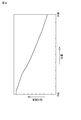
- FIG. 2 is a characteristic diagram showing the peripheral light quantity characteristic of the condenser lens.
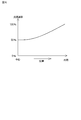
- FIG. 3 is a characteristic diagram showing an integrated characteristic of correction with respect to the light quantity characteristic of the condenser lens when the peripheral light quantity reduction is corrected by the signal processing system.
- FIG. 4A is a cross-sectional view showing an example of a formation part of a gradation ND filter for an infrared light cut filter
- FIG. 4B is a cross-sectional view showing an example of a formation part of a gradation ND filter for a condenser lens.
- FIG. 1 is a cross-sectional view illustrating a cross-sectional structure of a camera module according to the first embodiment of the present disclosure.
- FIG. 2 is a characteristic diagram showing the peripheral light quantity characteristic of the condenser lens.
- FIG. 3 is a characteristic diagram
- FIG. 5A is a diagram illustrating a case where the shape of the ND filter is a square
- FIG. 5B is a diagram illustrating a case where the shape of the ND filter is a circle
- FIG. 6 is a diagram illustrating an example of gradation characteristics of the ND filter.
- FIG. 7 is a cross-sectional view illustrating a cross-sectional structure of a camera module according to the second embodiment of the present disclosure.
- FIG. 8 is a cross-sectional view showing a cross-sectional structure of a camera module according to a modification of the second embodiment.
- FIG. 9 is a block diagram illustrating a configuration of an imaging apparatus that is an example of the electronic apparatus of the present disclosure.
- FIG. 10 is a diagram illustrating an example of a schematic configuration of an endoscopic surgery system.
- FIG. 11 is a block diagram showing an example of the functional configuration of the camera head and CCU shown in FIG.
- FIG. 12 is a block diagram illustrating an example of a schematic configuration of the vehicle control system.
- FIG. 13 is an explanatory diagram illustrating an example of the installation positions of the outside-vehicle information detection unit and the imaging unit.
- the camera module according to the present disclosure can be configured to include a solid-state imaging device that receives light that has been stored in a package made of a light-transmitting material and passed through the imaging optical system.
- the imaging optical system is disposed on the light incident side of the solid-state imaging device.
- the imaging optical system of the present disclosure the imaging optical system in the camera module of the present disclosure including the preferred configuration described above, and the imaging optical system in the electronic apparatus of the present disclosure (hereinafter collectively referred to as “the imaging optical system of the present disclosure
- the optical member may be composed of an ND filter whose light transmittance increases from the central portion toward the peripheral portion.
- the ND filter preferably has gradation characteristics.
- the light transmittance of the optical member can be configured to match the light amount characteristic of the lens.
- the optical member may be disposed away from the lens or may be configured on the lens.
- the optical member may be disposed away from the lens on the light incident side of the lens, or may be disposed away from the lens on the light exit side of the lens.
- the optical member may be provided on the light incident surface of the lens, may be provided on the light exit surface of the lens, or on the light entrance surface and the light exit surface of the lens. May be provided.
- an optical member is formed on at least one lens constituting the lens system.
- the imaging optical system of the present disclosure including the various preferable configurations described above, It has an infrared light cut filter,
- the optical member may be disposed separately from the infrared light cut filter, or may be configured on the infrared light cut filter.
- the optical member can be arranged on the light incident side of the infrared light cut filter and separated from the infrared light cut filter, and the infrared light cut on the light output side of the infrared light cut filter. It can be disposed away from the filter, and can be disposed away from the infrared light cut filter on the light incident side and light output side of the infrared light cut filter.
- the optical member may be formed on the light incident surface of the infrared light cut filter, may be formed on the light emission surface of the infrared light cut filter, or may be formed on the infrared light cut filter. It may be formed on the light incident surface and the light emitting surface.
- an optical member disposed away from the infrared light cut filter and an optical member formed on the infrared light cut filter may be combined.
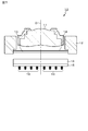
- FIG. 1 shows a cross-sectional structure of the camera module according to the first embodiment.
- the camera module according to the first embodiment is configured to include the imaging optical system of the present disclosure.
- the imaging optical system according to the first embodiment includes a lens (condensing lens 11) and an optical member (specifically, an ND filter 14), and the camera module 10 performs this imaging. It has an optical system.
- the camera module 10 according to the first embodiment includes a condenser lens 11, a lens driving unit 12, an infrared light cut filter (hereinafter referred to as “IR cut filter”) 13, and an ND filter 14. It has.
- the camera module 10 further includes a solid-state image sensor 15, a circuit board 16, and a metal wire 17.
- the condenser lens 11 captures and collects image light from a subject (not shown) as incident light, passes through the IR cut filter 13 and the like, and passes through the IR imaging filter 15. Guide on the imaging surface.
- the lens driving unit 12 includes an actuator or the like, and moves the condensing lens 11 in the direction of the optical axis O and fixes the condensing lens 11 at an optimum condensing position.
- the IR cut filter 13 is provided in the optical path of the imaging optical system, and removes an infrared light component included in the image light condensed by the condenser lens 11.
- the optical member has a value of light transmittance of at least the peripheral portion larger than that of the central portion (peripheral portion of the optical axis O including the optical axis O).
- the optical member includes the ND filter 14 whose light transmittance increases from the central portion toward the peripheral portion.
- the ND filter 14 has, for example, gradation characteristics.
- the ND filter having gradation characteristics is generally called a gradation ND filter.
- the optical member (ND filter 14) is specifically formed on the infrared light cut filter 13. More specifically, the ND filter 14 is made of, for example, a filter film formed (formed) over the entire surface (light incident surface) of the IR cut filter 13 on the condenser lens 11 side.
- the ND filter 14 is composed of, for example, an absorption ND filter.
- the gradation characteristic of the ND filter 14 is a characteristic in which the value of light transmittance increases from the optical center O (optical axis O) toward the peripheral portion (in other words, as the distance from the optical axis O increases). At this time, it is preferable that the value of the light transmittance changes continuously from the optical center O (optical axis O) toward the peripheral portion.
- “continuous” means not only strictly continuous but also substantially continuous, and the presence of various variations in design or manufacturing is allowed. Moreover, it may be stepwise.
- the light transmittance of the optical member (ND filter 14) is matched to the light amount characteristic of the condenser lens 11.
- the light transmittance of the gradation characteristic of the ND filter 14 changes in accordance with the light amount characteristic of the condenser lens 11 provided in the optical path of the imaging optical system. That is, for the gradation characteristics of the ND filter 14, the value of the light transmittance changes in accordance with the light quantity characteristic of the condenser lens 11, that is, the value of the light transmittance increases from the optical center O toward the peripheral portion. Is preferred.
- the solid-state imaging device 15 is composed of a CCD image sensor, a CMOS image sensor, or the like, and photoelectrically converts image light from the subject, which has passed through the ND filter 14 and from which the infrared light component has been removed by the IR cut filter 13, in units of pixels.
- the circuit board 16 is formed of a substrate material such as ceramic or glass epoxy, and has the solid-state imaging element 15 mounted thereon.
- the solid-state imaging device 15 is electrically connected to the circuit board 16 by, for example, a metal wire 17. On the circuit board 16, peripheral circuits of the solid-state imaging device 15 and the like are formed.
- the imaging optical system of the camera module 10 preferably transmits light in the optical path of the imaging optical system from the optical center O toward the periphery (as the distance from the optical axis O increases). It is characterized in that an ND filter (gradation ND filter) having gradation characteristics that increases the value of the rate is provided.
- ND filter gradient ND filter
- the imaging optical system when the gradation ND filter 14 is not provided will be considered.
- the peripheral light amount characteristic of the general condensing lens 11 arranged in the optical path of the imaging optical system has a light amount ratio of the peripheral portion to the central portion of about 20%.
- the problem of the decrease in the amount of peripheral light has been dealt with by correcting the signal at the periphery of the screen where the amount of light has decreased by the signal processing system of the solid-state imaging device.
- FIG. 3 shows a correction integrated characteristic with respect to the light quantity characteristic of the condenser lens 11 when the peripheral light quantity reduction is corrected by the signal processing system.
- the signal processing system corrects the decrease in the peripheral light amount
- the signal in the peripheral portion of the screen where the light amount is reduced is amplified.
- the noise component is amplified.
- problems such as emphasis on noise components, flaws on solid-state image sensors, emphasis on fine dust adhering to solid-state image sensors, and emphasis on unevenness of solid-state image sensors and optical materials This also causes a problem in that the yield decreases.
- the ND filter 14 in which at least the light transmittance of the peripheral portion is larger than the light transmittance of the central portion in the optical path of the imaging optical system.
- the correction in the signal processing is not denied, and a mode in which the optical correction in the imaging optical system is the main correction and the correction in the signal processing is the sub correction can be adopted.
- a mode in which the optical correction in the imaging optical system is the main correction and the correction in the signal processing is the sub correction can be adopted.
- the peripheral light amount decrease can be optically corrected, even if the aperture of the condenser lens 11 is increased, non-uniformity in the light amount due to the light amount decrease does not occur. Can solve the problem. Since the problem of the small aperture diffraction of the condenser lens 11 can be solved, the pixels of a solid-state image sensor such as a CCD image sensor or a CMOS image sensor can be miniaturized, so that high-definition images can be captured. Become.
- the ND filter 14 has a gradation characteristic in which the light transmittance increases from the optical center O toward the peripheral portion in accordance with the light amount characteristic of the condenser lens 11, the optical center O extends from the optical center O to the peripheral portion. Uniform brightness (luminance) can be realized.
- the design of the condensing lens 11 can relax the optical design for peripheral brightness correction (shading correction), and thus the number of lenses constituting the condensing lens 11 can be reduced. Further, since the number of lenses can be reduced, cost reduction and height reduction can be achieved.
- the optical design for shading correction can be relaxed, distortion (image distortion) can be improved.
- the ND filter 14 is formed (film-formed) on the light incident surface of the IR cut filter 13, but as shown in FIG. 4A, the light exit surface (the surface on the solid-state imaging device 15 side). Alternatively, it may be formed (film formation) or may be formed (film formation) on both the light incident surface and the light emission surface. That is, a configuration in which the ND filter 14 is formed on at least one of the light incident surface and the light emitting surface of the IR cut filter 13 as an optical member having a light transmittance at least in the peripheral portion larger than the light transmittance in the central portion. Can be taken.
- the optical member may be disposed separately from the condensing lens 11 or may be formed on the condensing lens 11. That is, as shown in FIG. 4B, the ND filter 14 may be formed (formed) on at least one of the light incident surface and the light emitting surface of the condenser lens 11.
- the condensing lens 11 is composed of a combination of a plurality of lenses, and thus is formed (deposited) on the surface of the condensing lens 11, specifically, the lens inside the condensing lens 11. ).
- the structure which forms the ND filter 14 in at least one place of the surface can be taken.
- the characteristics, processing accuracy, and manufacturing of the condenser lens 11 are determined with respect to the formation position. It can be changed as appropriate according to the method.
- the shape of the ND filter 14 may be a square shape shown in FIG. 5A or a circular shape shown in FIG. 5B. it can. Further, when the ND filter 14 is formed on the lens (when the ND filter 14 is formed on at least one place on the incident surface of the condenser lens 11, the inside of the condenser lens 11, and the exit surface of the condenser lens 11), the ND filter 14. The shape of can be a circle shown in FIG. 5B. As is clear from FIGS. 5A and 5B, the ND filter 14 has a gradation characteristic in which the value of light transmittance increases from the center to the periphery.
- FIG. 6 An example of gradation characteristics of the ND filter 14 is shown in FIG.
- the gradation characteristic shown in FIG. 6 is an example, and the present invention is not limited to this. That is, the gradation characteristic of the ND filter 14 can be set to an arbitrary characteristic in accordance with the light amount characteristic of the condenser lens 11 provided in the optical path in the imaging optical system.
- Second Embodiment 2nd Embodiment of this indication is an example which accommodates a solid-state image sensor in a package.
- FIG. 7 shows a cross-sectional structure of the imaging optical system according to the second embodiment.
- the camera module according to the second embodiment is configured to include the imaging optical system according to the present disclosure.
- the camera module 10 according to the second embodiment is configured such that the solid-state imaging device 15 is mounted on a circuit board 16 in terms of configuration in that the solid-state imaging device 15 is packaged (stored) in a package 18 made of a light transmitting material.
- the ND filter 14 preferably has a gradation characteristic in which the value of the light transmittance continuously increases as it goes from the optical center O (optical axis O) toward the peripheral portion (as it goes away from the optical axis O). have.
- the package 18 for packaging the solid-state imaging device 15 is a package made of a light transmissive material such as glass as a main constituent material.
- a WLCSP Wafer Level Chip Size Package
- the size of the semiconductor chip obtained by cutting the wafer becomes the size of the package 18 as it is, so that the camera module 10 can be reduced in size and weight.
- the package 18 that houses the solid-state imaging device 15 is mounted on a circuit board via solder bumps 19.
- the ND filter 14 is formed (film formation) on the light incident surface of the IR cut filter 13 is illustrated, but as described in the first embodiment, the light incident of the IR cut filter 13 is described. It is possible to adopt a configuration in which it is formed (film formation) on at least one of the surface and the light exit surface. Furthermore, not only the IR cut filter 13 but also a configuration in which the light is formed on at least one of the light incident surface of the condenser lens 11, the inside of the condenser lens 11, and the light emission surface of the condenser lens 11 s can be adopted. .
- the ND filter 14 is formed on the surface of the package 18 on the imaging optical system side. It is also possible to adopt a configuration to When the ND filter 14 is formed on the IR cut filter 13 side, formed on the condenser lens 11 side, or formed on the package 18 side, the formation position is as follows. 11 can be appropriately changed according to the characteristics, processing accuracy, and manufacturing method.
- the same operations and effects as the camera module 10 according to the first embodiment can be obtained. That is, in order to solve the small-aperture diffraction problem of the condensing lens 11, non-uniformity in the amount of light caused by a decrease in the amount of peripheral light caused by increasing the aperture of the lens, This is not a correction in signal processing that causes problems such as emphasis on images and emphasis on fine dust, but can be corrected optically with an imaging optical system.
- the ND filter 14 has gradation characteristics in which the value of the light transmittance increases from the optical center O toward the peripheral part in accordance with the light amount characteristic of the condenser lens 11, Uniform brightness (luminance) can be realized over the portion.
- the optical design for shading correction can be relaxed, so that the number of lenses constituting the condenser lens 11 can be reduced. Further, since the number of lenses can be reduced, cost reduction and height reduction can be achieved. Further, since the optical design for shading correction can be relaxed, distortion can be improved.
- the camera module according to the first embodiment and the second embodiment described above includes an imaging device such as a digital still camera and a video camera, a portable terminal device having an imaging function such as a mobile phone, and a solid-state imaging device in an image reading unit. It can be used as an imaging unit (image capturing unit) in electronic devices such as copying machines using That is, the electronic apparatus includes a solid-state imaging device and the imaging optical system according to the first embodiment or the second embodiment.
- FIG. 9 is a block diagram illustrating a configuration of an imaging apparatus that is an example of the electronic apparatus of the present disclosure.
- the imaging apparatus 100 includes an imaging optical system 101, an imaging unit 102, a DSP (Digital Signal Processor) circuit 103, a frame memory 104, a display device 105, a recording device 106, an operation system 107, And a power supply system 108 and the like.
- the DSP circuit 103, the frame memory 104, the display device 105, the recording device 106, the operation system 107, and the power supply system 108 are connected to each other via a bus line 109.
- the imaging optical system 101 takes in incident light (image light) from a subject and forms an image on the imaging surface of the imaging unit 102.
- the imaging unit 102 converts the amount of incident light imaged on the imaging surface by the optical system 101 into an electrical signal for each pixel and outputs the electrical signal as a pixel signal.
- the DSP circuit 103 performs general camera signal processing, such as white balance processing, demosaic processing, and gamma correction processing.
- the frame memory 104 is used for storing data as appropriate during the signal processing in the DSP circuit 103.
- the display device 105 includes a panel type display device such as a liquid crystal display device or an organic EL (electroluminescence) display device, and displays a moving image or a still image captured by the imaging unit 102.
- the recording device 106 records the moving image or still image captured by the imaging unit 102 on a recording medium such as a portable semiconductor memory, an optical disk, or an HDD (Hard Disk Disk Drive).
- the operation system 107 issues operation commands for various functions of the imaging apparatus 100 under the operation of the user.
- the power supply system 108 appropriately supplies various power supplies serving as operation power for the DSP circuit 103, the frame memory 104, the display device 105, the recording device 106, and the operation system 107 to these supply targets.
- the camera module according to the first embodiment or the second embodiment described above can be used as the imaging optical system 101 and the imaging unit 102. Since the camera module according to these embodiments can achieve uniform brightness from the optical center to the periphery, the optical design for shading correction can be relaxed in the lens design of the imaging optical system 101. Therefore, the number of lenses can be reduced.
- the technique according to the present disclosure can solve the problem of small-aperture diffraction of the condensing lens, and accordingly, the pixels of the solid-state imaging device can be miniaturized, so that high-definition images can be captured. .
- the technology according to the present disclosure can be applied to various products other than the above-described imaging devices such as a digital still camera and a video camera.
- the technology according to the present disclosure may be applied to an endoscopic surgery system.
- the technology according to the present disclosure may be any kind of automobile, electric vehicle, hybrid electric vehicle, motorcycle, bicycle, personal mobility, airplane, drone, ship, robot, construction machine, agricultural machine (tractor), etc. You may implement
- FIG. 10 is a diagram illustrating an example of a schematic configuration of an endoscopic surgery system 5000 to which the technology according to the present disclosure can be applied.
- FIG. 10 shows a state where an operator (doctor) 5067 is performing surgery on a patient 5071 on a patient bed 5069 using an endoscopic surgery system 5000.
- an endoscopic surgery system 5000 includes an endoscope 5001, other surgical tools 5017, a support arm device 5027 that supports the endoscope 5001, and various devices for endoscopic surgery. And a cart 5037 on which is mounted.
- trocars 5025a to 5025d are punctured into the abdominal wall.
- the lens barrel 5003 of the endoscope 5001 and other surgical tools 5017 are inserted into the body cavity of the patient 5071 from the trocars 5025a to 5025d.
- an insufflation tube 5019, an energy treatment tool 5021, and forceps 5023 are inserted into the body cavity of the patient 5071.
- the energy treatment device 5021 is a treatment device that performs tissue incision and separation, blood vessel sealing, or the like by high-frequency current or ultrasonic vibration.
- the illustrated surgical tool 5017 is merely an example, and as the surgical tool 5017, for example, various surgical tools generally used in endoscopic surgery such as a lever and a retractor may be used.
- the image of the surgical site in the body cavity of the patient 5071 captured by the endoscope 5001 is displayed on the display device 5041.
- the surgeon 5067 performs a treatment such as excision of the affected part, for example, using the energy treatment tool 5021 and the forceps 5023 while viewing the image of the surgical part displayed on the display device 5041 in real time.
- the pneumoperitoneum tube 5019, the energy treatment tool 5021, and the forceps 5023 are supported by an operator 5067 or an assistant during surgery.
- the support arm device 5027 includes an arm portion 5031 extending from the base portion 5029.
- the arm portion 5031 includes joint portions 5033a, 5033b, and 5033c and links 5035a and 5035b, and is driven by control from the arm control device 5045.
- the endoscope 5001 is supported by the arm unit 5031, and the position and posture thereof are controlled. Thereby, the stable position fixing of the endoscope 5001 can be realized.
- the endoscope 5001 includes a lens barrel 5003 in which a region having a predetermined length from the distal end is inserted into the body cavity of the patient 5071, and a camera head 5005 connected to the proximal end of the lens barrel 5003.
- a lens barrel 5003 in which a region having a predetermined length from the distal end is inserted into the body cavity of the patient 5071, and a camera head 5005 connected to the proximal end of the lens barrel 5003.
- an endoscope 5001 configured as a so-called rigid mirror having a rigid lens barrel 5003 is illustrated, but the endoscope 5001 is configured as a so-called flexible mirror having a flexible lens barrel 5003. Also good.
- An opening into which an objective lens is fitted is provided at the tip of the lens barrel 5003.
- a light source device 5043 is connected to the endoscope 5001, and light generated by the light source device 5043 is guided to the tip of the lens barrel by a light guide extending inside the lens barrel 5003. Irradiation is performed toward the observation target in the body cavity of the patient 5071 through the lens.
- the endoscope 5001 may be a direct endoscope, a perspective mirror, or a side endoscope.
- An optical system and an image sensor are provided inside the camera head 5005, and reflected light (observation light) from the observation target is condensed on the image sensor by the optical system. Observation light is photoelectrically converted by the imaging element, and an electrical signal corresponding to the observation light, that is, an image signal corresponding to the observation image is generated.
- the image signal is transmitted to a camera control unit (CCU) 5039 as RAW data.
- CCU camera control unit
- the camera head 5005 is equipped with a function of adjusting the magnification and the focal length by appropriately driving the optical system.
- a plurality of imaging elements may be provided in the camera head 5005 in order to cope with, for example, stereoscopic viewing (3D display).
- a plurality of relay optical systems are provided inside the lens barrel 5003 in order to guide observation light to each of the plurality of imaging elements.
- the CCU 5039 is configured by a CPU (Central Processing Unit), a GPU (Graphics Processing Unit), and the like, and comprehensively controls operations of the endoscope 5001 and the display device 5041. Specifically, the CCU 5039 performs various types of image processing for displaying an image based on the image signal, such as development processing (demosaic processing), for example, on the image signal received from the camera head 5005. The CCU 5039 provides the display device 5041 with the image signal subjected to the image processing. Further, the CCU 5039 transmits a control signal to the camera head 5005 to control the driving thereof.
- the control signal can include information regarding imaging conditions such as magnification and focal length.
- the display device 5041 displays an image based on an image signal subjected to image processing by the CCU 5039 under the control of the CCU 5039.
- the endoscope 5001 is compatible with high-resolution imaging such as 4K (horizontal pixel number 3840 ⁇ vertical pixel number 2160) or 8K (horizontal pixel number 7680 ⁇ vertical pixel number 4320), and / or 3D display
- the display device 5041 may be a display device capable of high-resolution display and / or 3D display.
- 4K or 8K high-resolution imaging a more immersive feeling can be obtained by using a display device 5041 having a size of 55 inches or more.
- a plurality of display devices 5041 having different resolutions and sizes may be provided depending on applications.
- the light source device 5043 is composed of a light source such as an LED (light emitting diode), for example, and supplies irradiation light to the endoscope 5001 when photographing a surgical site.
- a light source such as an LED (light emitting diode)
- the arm control device 5045 is configured by a processor such as a CPU, for example, and operates according to a predetermined program to control driving of the arm portion 5031 of the support arm device 5027 according to a predetermined control method.
- the input device 5047 is an input interface for the endoscopic surgery system 5000.
- the user can input various information and instructions to the endoscopic surgery system 5000 via the input device 5047.
- the user inputs various types of information related to the operation, such as the patient's physical information and information about the surgical technique, via the input device 5047.
- the user instructs the arm unit 5031 to be driven via the input device 5047 or the instruction to change the imaging conditions (type of irradiation light, magnification, focal length, etc.) by the endoscope 5001. Then, an instruction to drive the energy treatment instrument 5021 is input.
- the type of the input device 5047 is not limited, and the input device 5047 may be various known input devices.
- the input device 5047 for example, a mouse, a keyboard, a touch panel, a switch, a foot switch 5057, and / or a lever can be applied.
- the touch panel may be provided on the display surface of the display device 5041.
- the input device 5047 is a device worn by the user, such as a glasses-type wearable device or an HMD (Head Mounted Display), and various types of input are performed according to the user's gesture and line of sight detected by these devices. Is done.
- the input device 5047 includes a camera capable of detecting the user's movement, and various inputs are performed according to the user's gesture and line of sight detected from the video captured by the camera.
- the input device 5047 includes a microphone that can pick up a user's voice, and various inputs are performed by voice through the microphone.
- the input device 5047 is configured to be able to input various information without contact, so that a user belonging to a clean area (for example, an operator 5067) can operate a device belonging to an unclean area without contact. Is possible.
- a user belonging to a clean area for example, an operator 5067
- the user can operate the device without releasing his / her hand from the surgical tool he / she has, the convenience for the user is improved.
- the treatment instrument control device 5049 controls the drive of the energy treatment instrument 5021 for tissue cauterization, incision, or blood vessel sealing.
- the pneumoperitoneum device 5051 gas is introduced into the body cavity via the pneumoperitoneum tube 5019.
- the recorder 5053 is an apparatus capable of recording various types of information related to surgery.
- the printer 5055 is a device that can print various types of information related to surgery in various formats such as text, images, or graphs.
- the support arm device 5027 includes a base portion 5029 as a base and an arm portion 5031 extending from the base portion 5029.
- the arm portion 5031 includes a plurality of joint portions 5033a, 5033b, and 5033c and a plurality of links 5035a and 5035b connected by the joint portion 5033b.
- FIG. The configuration of the arm portion 5031 is shown in a simplified manner. Actually, the shape, number and arrangement of the joint portions 5033a to 5033c and the links 5035a and 5035b, the direction of the rotation axis of the joint portions 5033a to 5033c, and the like are appropriately set so that the arm portion 5031 has a desired degree of freedom. obtain.
- the arm portion 5031 can be preferably configured to have 6 degrees of freedom or more. Accordingly, the endoscope 5001 can be freely moved within the movable range of the arm portion 5031. Therefore, the barrel 5003 of the endoscope 5001 can be inserted into the body cavity of the patient 5071 from a desired direction. It becomes possible.
- the joint portions 5033a to 5033c are provided with actuators, and the joint portions 5033a to 5033c are configured to be rotatable around a predetermined rotation axis by driving the actuators.
- the arm control device 5045 By controlling the driving of the actuator by the arm control device 5045, the rotation angles of the joint portions 5033a to 5033c are controlled, and the driving of the arm portion 5031 is controlled. Thereby, control of the position and orientation of the endoscope 5001 can be realized.
- the arm control device 5045 can control the driving of the arm unit 5031 by various known control methods such as force control or position control.
- the arm control device 5045 appropriately controls the driving of the arm unit 5031 according to the operation input.
- the position and posture of the endoscope 5001 may be controlled.
- the endoscope 5001 at the tip of the arm portion 5031 can be moved from an arbitrary position to an arbitrary position, and then fixedly supported at the position after the movement.
- the arm portion 5031 may be operated by a so-called master slave method.
- the arm unit 5031 can be remotely operated by the user via the input device 5047 installed at a location away from the operating room.
- the arm control device 5045 When force control is applied, the arm control device 5045 receives the external force from the user and moves the actuators of the joint portions 5033a to 5033c so that the arm portion 5031 moves smoothly according to the external force. You may perform what is called power assist control to drive. Accordingly, when the user moves the arm unit 5031 while directly touching the arm unit 5031, the arm unit 5031 can be moved with a relatively light force. Therefore, the endoscope 5001 can be moved more intuitively and with a simpler operation, and user convenience can be improved.
- an endoscope 5001 is supported by a doctor called a scopist.
- the position of the endoscope 5001 can be more reliably fixed without relying on human hands, so that an image of the surgical site can be stably obtained. It becomes possible to perform the operation smoothly.
- the arm control device 5045 is not necessarily provided in the cart 5037. Further, the arm control device 5045 is not necessarily a single device. For example, the arm control device 5045 may be provided in each joint portion 5033a to 5033c of the arm portion 5031 of the support arm device 5027, and the plurality of arm control devices 5045 cooperate with each other to drive the arm portion 5031. Control may be realized.
- the light source device 5043 supplies irradiation light to the endoscope 5001 when photographing a surgical site.
- the light source device 5043 is composed of a white light source composed of, for example, an LED, a laser light source, or a combination thereof.
- a white light source is configured by a combination of RGB laser light sources, the output intensity and output timing of each color (each wavelength) can be controlled with high accuracy. Adjustments can be made.
- each RGB light source is controlled by irradiating the observation target with laser light from each of the RGB laser light sources in a time-sharing manner and controlling the driving of the image sensor of the camera head 5005 in synchronization with the irradiation timing. It is also possible to take the images that have been taken in time division. According to this method, a color image can be obtained without providing a color filter in the image sensor.
- the driving of the light source device 5043 may be controlled so as to change the intensity of the output light every predetermined time.
- the driving of the image sensor of the camera head 5005 is controlled to acquire images in a time-sharing manner, and the images are synthesized, so that high dynamics without so-called blackout and overexposure are obtained. A range image can be generated.
- the light source device 5043 may be configured to be able to supply light of a predetermined wavelength band corresponding to special light observation.
- special light observation for example, by utilizing the wavelength dependence of light absorption in body tissue, the surface of the mucous membrane is irradiated by irradiating light in a narrow band compared to irradiation light (that is, white light) during normal observation.
- narrow band imaging is performed in which a predetermined tissue such as a blood vessel is imaged with high contrast.
- fluorescence observation may be performed in which an image is obtained by fluorescence generated by irradiating excitation light.
- the body tissue is irradiated with excitation light to observe fluorescence from the body tissue (autofluorescence observation), or a reagent such as indocyanine green (ICG) is locally administered to the body tissue and applied to the body tissue.
- a reagent such as indocyanine green (ICG) is locally administered to the body tissue and applied to the body tissue.
- ICG indocyanine green
- the light source device 5043 can be configured to be able to supply narrowband light and / or excitation light corresponding to such special light observation.
- FIG. 11 is a block diagram showing an example of the functional configuration of the camera head 5005 and the CCU 5039 shown in FIG.
- the camera head 5005 has a lens unit 5007, an imaging unit 5009, a drive unit 5011, a communication unit 5013, and a camera head control unit 5015 as its functions.
- the CCU 5039 includes a communication unit 5059, an image processing unit 5061, and a control unit 5063 as its functions.
- the camera head 5005 and the CCU 5039 are connected to each other via a transmission cable 5065 so that they can communicate with each other.
- the lens unit 5007 is an optical system provided at a connection portion with the lens barrel 5003. Observation light captured from the tip of the lens barrel 5003 is guided to the camera head 5005 and enters the lens unit 5007.
- the lens unit 5007 is configured by combining a plurality of lenses including a zoom lens and a focus lens. The optical characteristics of the lens unit 5007 are adjusted so that the observation light is condensed on the light receiving surface of the image sensor of the imaging unit 5009. Further, the zoom lens and the focus lens are configured such that their positions on the optical axis are movable in order to adjust the magnification and focus of the captured image.
- the imaging unit 5009 is configured by an imaging element, and is disposed in the subsequent stage of the lens unit 5007.
- the observation light that has passed through the lens unit 5007 is collected on the light receiving surface of the image sensor, and an image signal corresponding to the observation image is generated by photoelectric conversion.
- the image signal generated by the imaging unit 5009 is provided to the communication unit 5013.
- CMOS Complementary Metal Oxide Semiconductor
- the imaging element for example, an element capable of capturing a high-resolution image of 4K or more may be used.
- the image sensor that configures the image capturing unit 5009 is configured to include a pair of image sensors for acquiring right-eye and left-eye image signals corresponding to 3D display. By performing the 3D display, the operator 5067 can more accurately grasp the depth of the living tissue in the surgical site.
- the imaging unit 5009 is configured as a multi-plate type, a plurality of lens units 5007 are also provided corresponding to each imaging element.
- the imaging unit 5009 is not necessarily provided in the camera head 5005.
- the imaging unit 5009 may be provided inside the lens barrel 5003 immediately after the objective lens.
- the driving unit 5011 includes an actuator, and moves the zoom lens and the focus lens of the lens unit 5007 by a predetermined distance along the optical axis under the control of the camera head control unit 5015. Thereby, the magnification and focus of the image captured by the imaging unit 5009 can be adjusted as appropriate.
- the communication unit 5013 is configured by a communication device for transmitting and receiving various types of information to and from the CCU 5039.
- the communication unit 5013 transmits the image signal obtained from the imaging unit 5009 as RAW data to the CCU 5039 via the transmission cable 5065.
- the image signal is preferably transmitted by optical communication.
- the surgeon 5067 performs the surgery while observing the state of the affected area with the captured image, so that a moving image of the surgical site is displayed in real time as much as possible for safer and more reliable surgery. Because it is required.
- the communication unit 5013 is provided with a photoelectric conversion module that converts an electrical signal into an optical signal.
- the image signal is converted into an optical signal by the photoelectric conversion module, and then transmitted to the CCU 5039 via the transmission cable 5065.
- the communication unit 5013 receives a control signal for controlling driving of the camera head 5005 from the CCU 5039.
- the control signal includes, for example, information for designating the frame rate of the captured image, information for designating the exposure value at the time of imaging, and / or information for designating the magnification and focus of the captured image. Contains information about the condition.
- the communication unit 5013 provides the received control signal to the camera head control unit 5015.
- the control signal from the CCU 5039 may also be transmitted by optical communication.
- the communication unit 5013 is provided with a photoelectric conversion module that converts an optical signal into an electric signal.
- the control signal is converted into an electric signal by the photoelectric conversion module, and then provided to the camera head control unit 5015.
- the imaging conditions such as the frame rate, exposure value, magnification, and focus are automatically set by the control unit 5063 of the CCU 5039 based on the acquired image signal. That is, a so-called AE (Auto Exposure) function, AF (Auto Focus) function, and AWB (Auto White Balance) function are mounted on the endoscope 5001.
- AE Auto Exposure
- AF Automatic Focus
- AWB Automatic White Balance
- the camera head control unit 5015 controls driving of the camera head 5005 based on a control signal from the CCU 5039 received via the communication unit 5013. For example, the camera head control unit 5015 controls driving of the imaging element of the imaging unit 5009 based on information indicating that the frame rate of the captured image is specified and / or information indicating that the exposure at the time of imaging is specified. For example, the camera head control unit 5015 appropriately moves the zoom lens and the focus lens of the lens unit 5007 via the drive unit 5011 based on information indicating that the magnification and focus of the captured image are designated.
- the camera head control unit 5015 may further have a function of storing information for identifying the lens barrel 5003 and the camera head 5005.
- the camera head 5005 can be resistant to autoclave sterilization by arranging the lens unit 5007, the imaging unit 5009, and the like in a sealed structure with high airtightness and waterproofness.
- the communication unit 5059 is configured by a communication device for transmitting and receiving various types of information to and from the camera head 5005.
- the communication unit 5059 receives an image signal transmitted from the camera head 5005 via the transmission cable 5065.
- the image signal can be suitably transmitted by optical communication.
- the communication unit 5059 is provided with a photoelectric conversion module that converts an optical signal into an electric signal.
- the communication unit 5059 provides the image processing unit 5061 with the image signal converted into the electrical signal.
- the communication unit 5059 transmits a control signal for controlling the driving of the camera head 5005 to the camera head 5005.
- the control signal may also be transmitted by optical communication.
- the image processing unit 5061 performs various types of image processing on the image signal that is RAW data transmitted from the camera head 5005. Examples of the image processing include development processing, high image quality processing (band enhancement processing, super-resolution processing, NR (Noise reduction) processing and / or camera shake correction processing, etc.), and / or enlargement processing (electronic zoom processing). Various known signal processing is included.
- the image processing unit 5061 performs detection processing on the image signal for performing AE, AF, and AWB.
- the image processing unit 5061 is configured by a processor such as a CPU or a GPU, and the above-described image processing and detection processing can be performed by the processor operating according to a predetermined program.
- the image processing unit 5061 is configured by a plurality of GPUs, the image processing unit 5061 appropriately divides information related to the image signal, and performs image processing in parallel by the plurality of GPUs.
- the control unit 5063 performs various controls relating to imaging of the surgical site by the endoscope 5001 and display of the captured image. For example, the control unit 5063 generates a control signal for controlling driving of the camera head 5005. At this time, when the imaging condition is input by the user, the control unit 5063 generates a control signal based on the input by the user. Alternatively, when the endoscope 5001 is equipped with the AE function, the AF function, and the AWB function, the control unit 5063 determines the optimum exposure value, focal length, and the like according to the detection processing result by the image processing unit 5061. A white balance is appropriately calculated and a control signal is generated.
- control unit 5063 causes the display device 5041 to display an image of the surgical site based on the image signal subjected to the image processing by the image processing unit 5061.
- the control unit 5063 recognizes various objects in the surgical unit image using various image recognition techniques. For example, the control unit 5063 detects the shape and color of the edge of the object included in the surgical part image, thereby removing surgical tools such as forceps, specific biological parts, bleeding, mist when using the energy treatment tool 5021, and the like. Can be recognized.
- the control unit 5063 displays various types of surgery support information on the image of the surgical site using the recognition result. Surgery support information is displayed in a superimposed manner and presented to the operator 5067, so that the surgery can be performed more safely and reliably.
- the transmission cable 5065 for connecting the camera head 5005 and the CCU 5039 is an electric signal cable corresponding to electric signal communication, an optical fiber corresponding to optical communication, or a composite cable thereof.
- communication is performed by wire using the transmission cable 5065, but communication between the camera head 5005 and the CCU 5039 may be performed wirelessly.
- communication between the two is performed wirelessly, there is no need to install the transmission cable 5065 in the operating room, so that the situation where the movement of the medical staff in the operating room is hindered by the transmission cable 5065 can be eliminated.
- the endoscopic surgery system 5000 to which the technology according to the present disclosure can be applied has been described.
- the endoscopic surgery system 5000 has been described as an example, but a system to which the technology according to the present disclosure can be applied is not limited to such an example.
- the technology according to the present disclosure may be applied to a testing flexible endoscope system or a microscope operation system.
- the technology according to the present disclosure can be suitably applied to the camera head 5005 among the configurations described above.
- the camera module according to the first embodiment or the second embodiment described above is used as an optical system and an imaging device provided inside the camera head 5005, more specifically, as the lens unit 5007 and the imaging unit 5009. Can be used.
- the technique according to the present disclosure to the camera head 5005, the number of lenses of the optical system can be reduced, so that the cost of the camera head 5005 can be reduced, and the cost of the endoscopic surgery system 5000 can be reduced.
- the technique according to the present disclosure can solve the problem of small aperture diffraction of the lens of the optical system, the pixels of the image sensor can be miniaturized. As a result, a high-definition image can be obtained, so that surgery can be performed more safely and reliably.
- FIG. 12 is a block diagram illustrating a schematic configuration example of a vehicle control system 7000 that is an example of a mobile control system to which the technology according to the present disclosure can be applied.
- the vehicle control system 7000 includes a plurality of electronic control units connected via a communication network 7010.
- the vehicle control system 7000 includes a drive system control unit 7100, a body system control unit 7200, a battery control unit 7300, an outside information detection unit 7400, an in-vehicle information detection unit 7500, and an integrated control unit 7600. .
- a communication network 7010 that connects the plurality of control units conforms to an arbitrary standard such as CAN (Controller Area Network), LIN (Local Interconnect Network), LAN (Local Area Network), or FlexRay (registered trademark). It may be an in-vehicle communication network.
- CAN Controller Area Network
- LIN Local Interconnect Network
- LAN Local Area Network
- FlexRay registered trademark
- Each control unit includes a microcomputer that performs arithmetic processing according to various programs, a storage unit that stores programs executed by the microcomputer or parameters used for various calculations, and a drive circuit that drives various devices to be controlled. Is provided.
- Each control unit includes a network I / F for communicating with other control units via a communication network 7010, and is connected to devices or sensors inside and outside the vehicle by wired communication or wireless communication. A communication I / F for performing communication is provided. In FIG.
- a microcomputer 7610 as a functional configuration of the integrated control unit 7600, a microcomputer 7610, a general-purpose communication I / F 7620, a dedicated communication I / F 7630, a positioning unit 7640, a beacon receiving unit 7650, an in-vehicle device I / F 7660, an audio image output unit 7670, An in-vehicle network I / F 7680 and a storage unit 7690 are illustrated.
- other control units include a microcomputer, a communication I / F, a storage unit, and the like.
- the drive system control unit 7100 controls the operation of the device related to the drive system of the vehicle according to various programs.
- the drive system control unit 7100 includes a driving force generator for generating a driving force of a vehicle such as an internal combustion engine or a driving motor, a driving force transmission mechanism for transmitting the driving force to wheels, and a steering angle of the vehicle. It functions as a control device such as a steering mechanism that adjusts and a braking device that generates a braking force of the vehicle.
- the drive system control unit 7100 may have a function as a control device such as ABS (Antilock Brake System) or ESC (Electronic Stability Control).
- a vehicle state detection unit 7110 is connected to the drive system control unit 7100.
- the vehicle state detection unit 7110 includes, for example, a gyro sensor that detects the angular velocity of the rotational movement of the vehicle body, an acceleration sensor that detects the acceleration of the vehicle, an operation amount of an accelerator pedal, an operation amount of a brake pedal, and steering of a steering wheel. At least one of sensors for detecting an angle, an engine speed, a rotational speed of a wheel, or the like is included.
- the drive system control unit 7100 performs arithmetic processing using a signal input from the vehicle state detection unit 7110, and controls an internal combustion engine, a drive motor, an electric power steering device, a brake device, or the like.
- the body system control unit 7200 controls the operation of various devices mounted on the vehicle body according to various programs.
- the body system control unit 7200 functions as a keyless entry system, a smart key system, a power window device, or a control device for various lamps such as a headlamp, a back lamp, a brake lamp, a blinker, or a fog lamp.
- the body control unit 7200 can be input with radio waves or various switch signals transmitted from a portable device that substitutes for a key.
- the body system control unit 7200 receives input of these radio waves or signals, and controls a door lock device, a power window device, a lamp, and the like of the vehicle.
- the battery control unit 7300 controls the secondary battery 7310 that is a power supply source of the drive motor according to various programs. For example, information such as battery temperature, battery output voltage, or remaining battery capacity is input to the battery control unit 7300 from a battery device including the secondary battery 7310. The battery control unit 7300 performs arithmetic processing using these signals, and controls the temperature adjustment of the secondary battery 7310 or the cooling device provided in the battery device.
- the outside information detection unit 7400 detects information outside the vehicle on which the vehicle control system 7000 is mounted.
- the outside information detection unit 7400 is connected to at least one of the imaging unit 7410 and the outside information detection unit 7420.
- the imaging unit 7410 includes at least one of a ToF (Time Of Flight) camera, a stereo camera, a monocular camera, an infrared camera, and other cameras.
- the outside information detection unit 7420 detects, for example, current weather or an environmental sensor for detecting weather, or other vehicles, obstacles, pedestrians, etc. around the vehicle equipped with the vehicle control system 7000. At least one of the surrounding information detection sensors.
- the environmental sensor may be, for example, at least one of a raindrop sensor that detects rainy weather, a fog sensor that detects fog, a sunshine sensor that detects sunlight intensity, and a snow sensor that detects snowfall.
- the ambient information detection sensor may be at least one of an ultrasonic sensor, a radar device, and a LIDAR (Light Detection and Ranging, Laser Imaging Detection and Ranging) device.
- the imaging unit 7410 and the outside information detection unit 7420 may be provided as independent sensors or devices, or may be provided as a device in which a plurality of sensors or devices are integrated.
- FIG. 13 shows an example of installation positions of the imaging unit 7410 and the vehicle outside information detection unit 7420.
- the imaging units 7910, 7912, 7914, 7916, and 7918 are provided at, for example, at least one of the front nose, the side mirror, the rear bumper, the back door, and the upper part of the windshield in the vehicle interior of the vehicle 7900.
- An imaging unit 7910 provided in the front nose and an imaging unit 7918 provided in the upper part of the windshield in the vehicle interior mainly acquire an image in front of the vehicle 7900.
- Imaging units 7912 and 7914 provided in the side mirror mainly acquire an image of the side of the vehicle 7900.
- An imaging unit 7916 provided in the rear bumper or the back door mainly acquires an image behind the vehicle 7900.
- the imaging unit 7918 provided on the upper part of the windshield in the passenger compartment is mainly used for detecting a preceding vehicle or a pedestrian, an obstacle, a traffic light, a traffic sign, a lane, or
- FIG. 13 shows an example of shooting ranges of the respective imaging units 7910, 7912, 7914, and 7916.
- the imaging range a indicates the imaging range of the imaging unit 7910 provided in the front nose
- the imaging ranges b and c indicate the imaging ranges of the imaging units 7912 and 7914 provided in the side mirrors, respectively
- the imaging range d The imaging range of the imaging part 7916 provided in the rear bumper or the back door is shown. For example, by superimposing the image data captured by the imaging units 7910, 7912, 7914, and 7916, an overhead image when the vehicle 7900 is viewed from above is obtained.
- the vehicle outside information detection units 7920, 7922, 7924, 7926, 7928, and 7930 provided on the front, rear, sides, corners of the vehicle 7900 and the upper part of the windshield in the vehicle interior may be, for example, an ultrasonic sensor or a radar device.
- the vehicle outside information detection units 7920, 7926, and 7930 provided on the front nose, the rear bumper, the back door, and the windshield in the vehicle interior of the vehicle 7900 may be, for example, LIDAR devices.
- These outside information detection units 7920 to 7930 are mainly used for detecting a preceding vehicle, a pedestrian, an obstacle, and the like.
- the vehicle exterior information detection unit 7400 causes the imaging unit 7410 to capture an image outside the vehicle and receives the captured image data. Further, the vehicle exterior information detection unit 7400 receives detection information from the vehicle exterior information detection unit 7420 connected thereto.
- the vehicle exterior information detection unit 7420 is an ultrasonic sensor, a radar device, or a LIDAR device
- the vehicle exterior information detection unit 7400 transmits ultrasonic waves, electromagnetic waves, or the like, and receives received reflected wave information.
- the outside information detection unit 7400 may perform an object detection process or a distance detection process such as a person, a car, an obstacle, a sign, or a character on a road surface based on the received information.
- the vehicle exterior information detection unit 7400 may perform environment recognition processing for recognizing rainfall, fog, road surface conditions, or the like based on the received information.
- the vehicle outside information detection unit 7400 may calculate a distance to an object outside the vehicle based on the received information.
- the outside information detection unit 7400 may perform image recognition processing or distance detection processing for recognizing a person, a car, an obstacle, a sign, a character on a road surface, or the like based on the received image data.
- the vehicle exterior information detection unit 7400 performs processing such as distortion correction or alignment on the received image data, and combines the image data captured by the different imaging units 7410 to generate an overhead image or a panoramic image. Also good.
- the vehicle exterior information detection unit 7400 may perform viewpoint conversion processing using image data captured by different imaging units 7410.
- the vehicle interior information detection unit 7500 detects vehicle interior information.
- a driver state detection unit 7510 that detects the driver's state is connected to the in-vehicle information detection unit 7500.
- Driver state detection unit 7510 may include a camera that captures an image of the driver, a biosensor that detects biometric information of the driver, a microphone that collects sound in the passenger compartment, and the like.
- the biometric sensor is provided, for example, on a seat surface or a steering wheel, and detects biometric information of an occupant sitting on the seat or a driver holding the steering wheel.
- the vehicle interior information detection unit 7500 may calculate the degree of fatigue or concentration of the driver based on the detection information input from the driver state detection unit 7510, and determines whether the driver is asleep. May be.
- the vehicle interior information detection unit 7500 may perform a process such as a noise canceling process on the collected audio signal.
- the integrated control unit 7600 controls the overall operation in the vehicle control system 7000 according to various programs.
- An input unit 7800 is connected to the integrated control unit 7600.
- the input unit 7800 is realized by a device that can be input by a passenger, such as a touch panel, a button, a microphone, a switch, or a lever.
- the integrated control unit 7600 may be input with data obtained by recognizing voice input through a microphone.
- the input unit 7800 may be, for example, a remote control device using infrared rays or other radio waves, or may be an external connection device such as a mobile phone or a PDA (Personal Digital Assistant) that supports the operation of the vehicle control system 7000. May be.
- the input unit 7800 may be, for example, a camera.
- the passenger can input information using a gesture.
- data obtained by detecting the movement of the wearable device worn by the passenger may be input.
- the input unit 7800 may include, for example, an input control circuit that generates an input signal based on information input by a passenger or the like using the input unit 7800 and outputs the input signal to the integrated control unit 7600.
- a passenger or the like operates the input unit 7800 to input various data or instruct a processing operation to the vehicle control system 7000.
- the storage unit 7690 may include a ROM (Read Only Memory) that stores various programs executed by the microcomputer, and a RAM (Random Access Memory) that stores various parameters, calculation results, sensor values, and the like.
- the storage unit 7690 may be realized by a magnetic storage device such as an HDD (Hard Disc Drive), a semiconductor storage device, an optical storage device, a magneto-optical storage device, or the like.
- General-purpose communication I / F 7620 is a general-purpose communication I / F that mediates communication with various devices existing in the external environment 7750.
- General-purpose communication I / F7620 is a cellular communication protocol such as GSM (registered trademark) (Global System of Mobile communications), WiMAX, LTE (Long Term Evolution) or LTE-A (LTE-Advanced), or a wireless LAN (Wi-Fi). (Also referred to as (registered trademark)) and other wireless communication protocols such as Bluetooth (registered trademark) may be implemented.
- GSM Global System of Mobile communications
- WiMAX Wireless LAN
- LTE Long Term Evolution
- LTE-A Long Term Evolution-A
- Wi-Fi wireless LAN
- Bluetooth registered trademark
- the general-purpose communication I / F 7620 is connected to a device (for example, an application server or a control server) existing on an external network (for example, the Internet, a cloud network, or an operator-specific network) via, for example, a base station or an access point. May be.
- the general-purpose communication I / F 7620 is a terminal (for example, a driver, a pedestrian or a store terminal, or an MTC (Machine Type Communication) terminal) that exists in the vicinity of the vehicle using, for example, P2P (Peer To Peer) technology. You may connect with.
- the dedicated communication I / F 7630 is a communication I / F that supports a communication protocol formulated for use in vehicles.
- the dedicated communication I / F 7630 is a standard protocol such as WAVE (Wireless Access in Vehicle Environment), DSRC (Dedicated Short Range Communications), or cellular communication protocol, which is a combination of the lower layer IEEE 802.11p and the upper layer IEEE 1609. May be implemented.
- the dedicated communication I / F 7630 typically includes vehicle-to-vehicle communication, vehicle-to-infrastructure communication, vehicle-to-home communication, and vehicle-to-pedestrian communication. ) Perform V2X communication, which is a concept that includes one or more of the communications.
- the positioning unit 7640 receives, for example, a GNSS signal from a GNSS (Global Navigation Satellite System) satellite (for example, a GPS signal from a GPS (Global Positioning System) satellite), performs positioning, and performs latitude, longitude, and altitude of the vehicle.
- the position information including is generated.
- the positioning unit 7640 may specify the current position by exchanging signals with the wireless access point, or may acquire position information from a terminal such as a mobile phone, PHS, or smartphone having a positioning function.
- the beacon receiving unit 7650 receives, for example, radio waves or electromagnetic waves transmitted from a radio station installed on the road, and acquires information such as the current position, traffic jam, closed road, or required time. Note that the function of the beacon receiving unit 7650 may be included in the dedicated communication I / F 7630 described above.
- the in-vehicle device I / F 7660 is a communication interface that mediates the connection between the microcomputer 7610 and various in-vehicle devices 7760 present in the vehicle.
- the in-vehicle device I / F 7660 may establish a wireless connection using a wireless communication protocol such as a wireless LAN, Bluetooth (registered trademark), NFC (Near Field Communication), or WUSB (Wireless USB).
- the in-vehicle device I / F 7660 is connected to a USB (Universal Serial Bus), HDMI (registered trademark) (High-Definition Multimedia Interface), or MHL (Mobile) via a connection terminal (and a cable if necessary). Wired connection such as High-definition Link) may be established.
- the in-vehicle device 7760 may include, for example, at least one of a mobile device or a wearable device that a passenger has, or an information device that is carried into or attached to the vehicle.
- In-vehicle device 7760 may include a navigation device that searches for a route to an arbitrary destination.
- In-vehicle device I / F 7660 exchanges control signals or data signals with these in-vehicle devices 7760.
- the in-vehicle network I / F 7680 is an interface that mediates communication between the microcomputer 7610 and the communication network 7010.
- the in-vehicle network I / F 7680 transmits and receives signals and the like in accordance with a predetermined protocol supported by the communication network 7010.
- the microcomputer 7610 of the integrated control unit 7600 is connected via at least one of a general-purpose communication I / F 7620, a dedicated communication I / F 7630, a positioning unit 7640, a beacon receiving unit 7650, an in-vehicle device I / F 7660, and an in-vehicle network I / F 7680.
- the vehicle control system 7000 is controlled according to various programs based on the acquired information. For example, the microcomputer 7610 calculates a control target value of the driving force generation device, the steering mechanism, or the braking device based on the acquired information inside and outside the vehicle, and outputs a control command to the drive system control unit 7100. Also good.
- the microcomputer 7610 realizes ADAS (Advanced Driver Assistance System) functions including vehicle collision avoidance or impact mitigation, following traveling based on inter-vehicle distance, vehicle speed maintaining traveling, vehicle collision warning, or vehicle lane departure warning. You may perform the cooperative control for the purpose. Further, the microcomputer 7610 controls the driving force generator, the steering mechanism, the braking device, or the like based on the acquired information on the surroundings of the vehicle, so that the microcomputer 7610 automatically travels independently of the driver's operation. You may perform the cooperative control for the purpose of driving.
- ADAS Advanced Driver Assistance System
- the microcomputer 7610 is information acquired via at least one of the general-purpose communication I / F 7620, the dedicated communication I / F 7630, the positioning unit 7640, the beacon receiving unit 7650, the in-vehicle device I / F 7660, and the in-vehicle network I / F 7680.
- the three-dimensional distance information between the vehicle and the surrounding structure or an object such as a person may be generated based on the above and local map information including the peripheral information of the current position of the vehicle may be created.
- the microcomputer 7610 may generate a warning signal by predicting a danger such as a collision of a vehicle, approach of a pedestrian or the like or an approach to a closed road based on the acquired information.
- the warning signal may be, for example, a signal for generating a warning sound or lighting a warning lamp.
- the audio image output unit 7670 transmits an output signal of at least one of audio and image to an output device capable of visually or audibly notifying information to a vehicle occupant or the outside of the vehicle.
- an audio speaker 7710, a display unit 7720, and an instrument panel 7730 are illustrated as output devices.
- Display unit 7720 may include at least one of an on-board display and a head-up display, for example.
- the display portion 7720 may have an AR (Augmented Reality) display function.
- the output device may be other devices such as headphones, wearable devices such as glasses-type displays worn by passengers, projectors, and lamps.
- the display device can display the results obtained by various processes performed by the microcomputer 7610 or information received from other control units in various formats such as text, images, tables, and graphs. Display visually. Further, when the output device is an audio output device, the audio output device converts an audio signal made up of reproduced audio data or acoustic data into an analog signal and outputs it aurally.
- At least two control units connected via the communication network 7010 may be integrated as one control unit.
- each control unit may be configured by a plurality of control units.
- the vehicle control system 7000 may include another control unit not shown.
- some or all of the functions of any of the control units may be given to other control units. That is, as long as information is transmitted and received via the communication network 7010, the predetermined arithmetic processing may be performed by any one of the control units.
- a sensor or device connected to one of the control units may be connected to another control unit, and a plurality of control units may transmit / receive detection information to / from each other via the communication network 7010. .
- the technology according to the present disclosure can be suitably applied to the imaging unit 7410 connected to the vehicle exterior information detection unit 7400 among the configurations described above.
- the imaging unit 7910, 7912, 7914, 7916, 7918 provided on the front nose of the vehicle 7900, the side mirror, the rear bumper, the back door, the upper part of the windshield in the vehicle interior, etc.
- the camera module according to the second embodiment can be used.
- Imaging optical system >> A lens and an optical member;
- the optical member is an imaging optical system in which at least the light transmittance value in the peripheral portion is larger than the light transmittance in the central portion.
- the imaging optical system according to [A01] in which the optical member includes an ND filter whose light transmittance increases from the central portion toward the peripheral portion.
- [A04] The imaging optical system according to any one of [A01] to [A03], wherein the optical member is disposed apart from the lens or formed on the lens. [A05] having an infrared light cut filter; The imaging optical system according to any one of [A01] to [A04], wherein the optical member is disposed apart from the infrared light cut filter or formed on the infrared light cut filter. . [B01] ⁇ Camera module >> A camera module including the imaging optical system according to any one of [A01] to [A05]. [B02] The camera module according to [B01], which includes a solid-state imaging device that receives light that has been stored in a package made of a light-transmitting material and has passed through the imaging optical system.
- Camera module >> A lens and an optical member;
- the optical member is an imaging optical system in which at least the light transmittance value in the peripheral portion is larger than the light transmittance in the central portion.
- the camera module according to [C01] including a solid-state imaging device that is received in a package made of a light-transmitting material and receives light that has passed through the imaging optical system.
- [C04] The camera module according to any one of [C01] to [C03], in which a light transmittance of the optical member is matched to a light amount characteristic of the lens.
- [C05] The camera module according to any one of [C01] to [C04], wherein the optical member is disposed away from the lens or formed on the lens.
- [C06] having an infrared light cut filter, The optical module is the camera module according to any one of [C01] to [C05], which is disposed apart from the infrared light cut filter or formed on the infrared light cut filter.
- the optical member is an imaging optical system in which at least the light transmittance value in the peripheral portion is larger than the light transmittance in the central portion.
- the electronic device according to [E01] wherein the solid-state imaging device is housed in a package made of a light transmitting material and receives light that has passed through the imaging optical system.
- the optical member includes an ND filter that increases light transmittance from the central portion toward the peripheral portion.
- [E04] The electronic device according to any one of [E01] to [E03], in which a light transmittance of the optical member is matched to a light amount characteristic of the lens.
- [E05] The electronic device according to any one of [E01] to [E04], wherein the optical member is disposed apart from the lens or formed on the lens.
- [E06] having an infrared light cut filter;
- DESCRIPTION OF SYMBOLS 10 ... Camera module, 11 ... Condensing lens, 12 ... Lens drive part, 13 ... IR cut filter (infrared light cut filter), 14 ... ND filter (gradation ND filter), DESCRIPTION OF SYMBOLS 15 ... Solid-state image sensor, 16 ... Circuit board, 17 ... Metal wire, 18 ... Package, 19 ... Solder bump
Abstract
本開示の撮像光学系は、レンズ、及び、光学部材を備えており、光学部材は、少なくとも周辺部の光透過率の値が中心部の光透過率よりも値が大きい。また、本開示のカメラモジュールは、本開示の撮像光学系を備えている。また、本開示の電子機器は、固体撮像素子、及び、本開示の撮像光学系を備えている。
Description
本開示は、撮像光学系、カメラモジュール、及び、電子機器に関する。
近年、デジタルスチルカメラやカメラ付き移動体端末装置などの撮像装置において、カメラの高画素化(多画素化)及び小型化が進んでいる。そして、カメラの高画素化及び小型化に伴って、撮像装置に実装されるCCDイメージセンサやCMOSイメージセンサなどの固体撮像素子の1画素のピッチが非常に小さくなってきている。
このような状況下において、被写体からの画像光(入射光)を取り込んで固体撮像素子の撮像面に導く撮像光学系のレンズの小絞り回折が問題となっている。この小絞り回折の問題を解決するためには、レンズの口径を大きくすることが必要である。しかし、レンズの口径を大きくすると、レンズの光学特性によって発生する、画面の周辺部(周縁部)で光量が低下する周辺光量低下(減光)の問題が新たに発生することが知られている。
そして、上記の周辺光量低下の問題については、一般的に、光量が低下した画面の周辺部の信号を、固体撮像素子の信号処理系で増幅することで対応するようにしていた。しかしながら、固体撮像素子の信号処理系での増幅処理では、ノイズ成分の強調、固体撮像素子の傷の強調、固体撮像素子に付着した微細なゴミの強調、固体撮像素子や光学材料のムラの強調などの問題が発生するため、撮像装置の歩留りの低下につながっている。
一方で、小絞り回折の問題を解決するために、光透過率が連続的に変化するグラデーションND(Neutral Density)フィルタを2枚対向して配置し、対称的に光路内に挿入/離脱させることにより、広い可変濃度範囲を持つ光量調整装置を実現する技術が提案されている(例えば、特許文献1参照)。
また、手ぶれ補正機能実行時、NDフィルタを光路に挿入することにより発生が懸念される周辺光量落ちを緩和するために、明るさの変化に応じてNDフィルタによる光量減衰量を変更し、光量減衰量が大きくなるに従い、像振れの補正範囲を小さくする技術が提案されている(例えば、特許文献2参照)。
特許文献1に記載の従来技術は、小絞り回折の問題については解決できるものの、レンズの光学特性に起因する周辺光量低下の問題については考慮されていない。また、特許文献2に記載の従来技術は、手ぶれ補正が行われても、NDフィルタのかかり方による周辺光量のアンバランスを目立ちにくくできるものの、レンズの光学特性に起因する周辺光量低下の問題については考慮されていない。
本開示は、レンズの光学特性に起因する周辺光量低下を、信号処理での補正ではなく、光学的に補正できる撮像光学系、当該撮像光学系を備えるカメラモジュール、及び、当該カメラモジュールを用いる電子機器を提供することを目的とする。
上記の目的を達成するための本開示の撮像光学系は、
レンズ、及び、光学部材を備えており、
光学部材は、少なくとも周辺部の光透過率の値が中心部の光透過率よりも値が大きい。
レンズ、及び、光学部材を備えており、
光学部材は、少なくとも周辺部の光透過率の値が中心部の光透過率よりも値が大きい。
また、上記の目的を達成するための本開示のカメラモジュールは、本開示の撮像光学系を備えている。
また、上記の目的を達成するための本開示の電子機器は、固体撮像素子、及び、本開示の撮像光学系を備えている。
本開示の撮像光学系、カメラモジュール、あるいは、電子機器にあっては、光学部材の少なくとも周辺部の光透過率の値が中心部の光透過率の値よりも大きいので、画面の周辺部(周縁部)での光量低下に起因した光量の不均一性が、光学部材によって光学的に補正される。即ち、本開示によれば、レンズの光学特性に基づく周辺光量低下に起因した光量の不均一性を、信号処理での補正ではなく、撮像光学系で光学的に補正することができる。なお、ここに記載された効果に必ずしも限定されるものではなく、本明細書中に記載されたいずれかの効果であってもよい。また、本明細書に記載された効果はあくまで例示であって、これに限定されるものではなく、また付加的な効果があってもよい。
以下、本開示に係る技術を実施するための形態(以下、「実施形態」と記述する)について図面を用いて詳細に説明する。本開示に係る技術は実施形態に限定されるものではない。以下の説明において、同一要素又は同一機能を有する要素には同一符号を用いることとし、重複する説明は省略する。なお、説明は以下の順序で行う。
1.本開示の撮像光学系、カメラモジュール、及び、電子機器、全般に関する説明
2.第1実施形態(固体撮像素子を回路基板に実装する例)
3.第2実施形態(固体撮像素子をパッケージに収納する例)
4.本開示の電子機器(撮像装置の例)
5.応用例
5-1.内視鏡手術システム
5-2.移動体に搭載される装置
6.本開示がとることができる構成
1.本開示の撮像光学系、カメラモジュール、及び、電子機器、全般に関する説明
2.第1実施形態(固体撮像素子を回路基板に実装する例)
3.第2実施形態(固体撮像素子をパッケージに収納する例)
4.本開示の電子機器(撮像装置の例)
5.応用例
5-1.内視鏡手術システム
5-2.移動体に搭載される装置
6.本開示がとることができる構成
<本開示の撮像光学系、カメラモジュール、及び、電子機器、全般に関する説明>
本開示のカメラモジュールにあっては、光透過材料から成るパッケージに収納され、撮像光学系を通過した光を受光する固体撮像素子を有する構成とすることができる。ここで、撮像光学系は、当然のことながら、固体撮像素子の光入射側に配設されている。
本開示のカメラモジュールにあっては、光透過材料から成るパッケージに収納され、撮像光学系を通過した光を受光する固体撮像素子を有する構成とすることができる。ここで、撮像光学系は、当然のことながら、固体撮像素子の光入射側に配設されている。
本開示の撮像光学系、上記の好ましい構成を含む本開示のカメラモジュールにおける撮像光学系、及び、本開示の電子機器における撮像光学系(以下、これらを総称して、『本開示の撮像光学系等』と呼ぶ)において、光学部材は、中心部から周辺部に向かって光透過率が大きくなるNDフィルタから成る構成とすることができる。ここで、NDフィルタは、グラデーション特性を有することが好ましい。
上述した好ましい構成を含む本開示の撮像光学系等において、光学部材の光透過率は、レンズの光量特性に合わせられている構成とすることができる。
上述した各種の好ましい構成を含む本開示の撮像光学系等において、光学部材は、レンズと離間して配設され、又は、レンズ上に形成されている構成とすることができる。具体的には、前者において、光学部材は、レンズの光入射側においてレンズと離間して配設されていてもよいし、レンズの光出射側においてレンズと離間して配設されていてもよい。また、後者において、光学部材は、レンズの光入射面上に設けられていてもよいし、レンズの光出射面上に設けられていてもよいし、レンズの光入射面上及び光出射面上に設けられていてもよい。レンズが、複数のレンズが組み合わされたレンズ系から構成されている場合、レンズ系を構成する少なくとも1枚のレンズの上に光学部材が形成されている。
上述した各種の好ましい構成を含む本開示の撮像光学系等は、
赤外光カットフィルタを有しており、
光学部材は、赤外光カットフィルタと離間して配設されており、又は、赤外光カットフィルタ上に形成されている構成とすることができる。
赤外光カットフィルタを有しており、
光学部材は、赤外光カットフィルタと離間して配設されており、又は、赤外光カットフィルタ上に形成されている構成とすることができる。
光学部材は、具体的には、赤外光カットフィルタの光入射側に赤外光カットフィルタと離間して配設することができるし、赤外光カットフィルタの光出射側に赤外光カットフィルタと離間して配設することができるし、赤外光カットフィルタの光入射側及び光出射側に赤外光カットフィルタと離間して配設することができる。あるいは又、光学部材は、赤外光カットフィルタの光入射面上に形成されていてもよいし、赤外光カットフィルタの光出射面上に形成されていてもよいし、赤外光カットフィルタの光入射面上及び光出射面上に形成されていてもよい。更には、赤外光カットフィルタと離間して配設された光学部材と、赤外光カットフィルタ上に形成された光学部材とを組み合わせることもできる。
<第1実施形態>
本開示の第1実施形態は、固体撮像素子を回路基板に実装する例である。第1実施形態に係るカメラモジュールの断面構造を図1に示す。第1実施形態に係るカメラモジュールは、本開示の撮像光学系を含む構成となっている。
本開示の第1実施形態は、固体撮像素子を回路基板に実装する例である。第1実施形態に係るカメラモジュールの断面構造を図1に示す。第1実施形態に係るカメラモジュールは、本開示の撮像光学系を含む構成となっている。
図1に示すように、第1実施形態に係る撮像光学系は、レンズ(集光レンズ11)及び光学部材(具体的には、NDフィルタ14)を備えているし、カメラモジュール10はこの撮像光学系を備えている。具体的には、第1実施形態に係るカメラモジュール10は、集光レンズ11、レンズ駆動部12、赤外光カットフィルタ(以下、「IRカットフィルタ」と記述する)13、及び、NDフィルタ14を備えている。カメラモジュール10は更に、固体撮像素子15、回路基板16、及び、金属ワイヤー17を有している。
上記の構成のカメラモジュール10において、集光レンズ11は、入射光である被写体(図示せず)からの画像光を取り込んで集光し、IRカットフィルタ13等を透して固体撮像素子15の撮像面上に導く。レンズ駆動部12は、アクチュエータ等から成り、集光レンズ11をその光軸Oの方向に移動させるとともに、集光レンズ11の最適な集光位置に固定する。IRカットフィルタ13は、撮像光学系の光路中に設けられており、集光レンズ11によって集光された画像光に含まれる赤外光成分を除去する。
光学部材は、少なくとも周辺部の光透過率の値が中心部(光軸Oを含む光軸Oの周辺部)の光透過率よりも値が大きい。即ち、光学部材は、中心部から周辺部に向かって光透過率が大きくなるNDフィルタ14から成る。ここで、NDフィルタ14は、例えば、グラデーション特性を有する。なお、グラデーション特性を有するNDフィルタは、一般的に、グラデーションNDフィルタと呼称されている。また、光学部材(NDフィルタ14)は、具体的には、赤外光カットフィルタ13の上に形成されている。より具体的には、NDフィルタ14は、例えば、IRカットフィルタ13の集光レンズ11側の面(光入射面)に全面に亘って形成(成膜)されたフィルタ膜から成る。ここで、NDフィルタ14は、例えば、吸収型のNDフィルタから構成されている。
NDフィルタ14のグラデーション特性は、光学中心O(光軸O)から周辺部に向かって(換言すれば、光軸Oから離れるに従って)光透過率の値が大きくなる特性である。このとき、光透過率の値は、光学中心O(光軸O)から周辺部に向かって連続的に変化することが好ましい。ここで、「連続的」とは、厳密に連続的である場合の他、実質的に連続的である場合も含む意味であり、設計上あるいは製造上生ずる種々のばらつきの存在は許容される。また、段階的であってもよい。光学部材(NDフィルター14)の光透過率は、集光レンズ11の光量特性に合わせられている。即ち、NDフィルタ14のグラデーション特性の光透過率は、撮像光学系の光路中に設けられている集光レンズ11の光量特性に合わせて変化することが好ましい。即ち、NDフィルタ14のグラデーション特性については、集光レンズ11の光量特性に合わせて光透過率の値が変化する、即ち、光学中心Oから周辺部に向かうにつれて光透過率の値が大きくなることが好ましい。
固体撮像素子15は、CCDイメージセンサやCMOSイメージセンサなどから成り、NDフィルタ14を透過し、IRカットフィルタ13で赤外光成分が除去された、被写体からの画像光を画素単位で光電変換する。回路基板16は、セラミックやガラスエポキシなどの基板材料で成形されており、固体撮像素子15を実装している。固体撮像素子15は、回路基板16に対して例えば金属ワイヤー17によって電気的に接続されている。回路基板16には、固体撮像素子15の周辺回路などが形成されている。
上述したように、第1実施形態に係るカメラモジュール10の撮像光学系は、撮像光学系の光路中に、好ましくは、光学中心Oから周辺部に向かって(光軸Oから離れるに従って)光透過率の値が大きくなるグラデーション特性を有するNDフィルタ(グラデーションNDフィルタ)が設けられていることを特徴としている。
ここで、グラデーションNDフィルタ14を持たない場合の撮像光学系について考察する。撮像光学系の光路中に配される、一般的な集光レンズ11の周辺光量特性は、図2に示すように、中心部に対する周辺部の光量比が20%程度である。この周辺光量低下の問題については、従来、光量が低下した画面の周辺部の信号を、固体撮像素子の信号処理系で補正することで対応するようにしていた。図3に、周辺光量低下を信号処理系で補正する場合の、集光レンズ11の光量特性に対する補正の積算特性を示す。
周辺光量低下を信号処理系で補正する場合、光量が低下した画面の周辺部の信号を増幅する処理となるが、このとき、光量成分だけでなく、ノイズ成分についても増幅されることになる。その結果、信号処理系での補正処理では、ノイズ成分の強調、固体撮像素子の傷の強調、固体撮像素子に付着した微細なゴミの強調、固体撮像素子や光学材料のムラの強調などの問題が発生し、歩留り低下となることも併せて問題となる。
これに対し、第1実施形態に係るカメラモジュール10における撮像光学系では、撮像光学系の光路中に、少なくとも周辺部の光透過率が中心部の光透過率よりも大きな値を有するNDフィルタ14を有することで、次のような作用、効果を得ることができる。即ち、集光レンズ11の小絞り回折問題の解決のために、レンズの口径を大きくすることで発生する周辺光量低下に起因した光量の不均一性を、ノイズ成分の強調、固体撮像素子の傷の強調や微細なゴミの強調などの問題が発生する信号処理での補正ではなく、撮像光学系で光学的に補正できる。
但し、信号処理での補正を否定するものではなく、撮像光学系での光学的な補正を主たる補正とし、信号処理での補正を副たる補正とする形態を採用することもできる。即ち、撮像光学系での光学的な補正では充分でない固体撮像素子の領域における補正を、信号処理での補正で補う形態を採用することもできる。
換言すれば、周辺光量低下を光学的に補正できることにより、集光レンズ11の口径を大きくしても、光量低下に起因した光量の不均一さが発生しないため、集光レンズ11の小絞り回折の問題を解決することができる。そして、集光レンズ11の小絞り回折の問題を解決できることにより、CCDイメージセンサやCMOSイメージセンサなどの固体撮像素子の画素の微細化を図ることができるため、高精細な画像の撮像が可能になる。
特に、NDフィルタ14が、集光レンズ11の光量特性に合わせて光透過率が、光学中心Oから周辺部に向かうにつれて大きくなるグラデーション特性を有しているために、光学中心Oから周辺部に亘って均一性のある明るさ(輝度)を実現することができる。その結果、集光レンズ11の設計において、周辺の明るさ補正(シェーディング補正)の光学設計を緩和できるため、集光レンズ11を構成するレンズ枚数を削減できる。そして、レンズ枚数を削減できることにより、コスト低減及び低背化を図ることができる。また、シェーディング補正の光学設計を緩和できることにより、ディストーション(画像の歪み)の改善を図ることができる。
なお、第1実施形態では、NDフィルタ14を、IRカットフィルタ13の光入射面に形成(成膜)するとしたが、図4Aに示すように、光出射面(固体撮像素子15側の面)に形成(成膜)するようにしてもよいし、あるいは、光入射面及び光出射面の双方に形成(成膜)るようにしてもよい。即ち、少なくとも周辺部の光透過率が中心部の光透過率よりも大きな値を有する光学部材として、IRカットフィルタ13の光入射面及び光出射面の少なくとも一方に、NDフィルタ14を形成する構成を採ることができる。
また、光学部材を、集光レンズ11と離間して配設してもよいし、集光レンズ11上に形成してもよい。即ち、図4Bに示すように、NDフィルタ14を、集光レンズ11の光入射面及び光出射面の少なくとも一方の上に形成(成膜)するようにしてもよい。あるいは又、周知のように、集光レンズ11は複数枚のレンズの組み合わせから成ることから、集光レンズ11内、具体的には集光レンズ11の内部側のレンズの表面に形成(成膜)するようにしてもよい。即ち、少なくとも周辺部の光透過率が中心部の光透過率よりも大きな値を有する光学部材として、集光レンズ11の光入射面、集光レンズ11内、及び、集光レンズ11の光出射面の少なくとも1箇所に、NDフィルタ14を形成する構成を採ることができる。
なお、NDフィルタ14を、IRカットフィルタ13側に形成する場合、集光レンズ11側に形成する場合のいずれの場合にも、その形成位置については、集光レンズ11の特性や加工精度、製造方法に応じて、適宜変更することができる。
NDフィルタ14を、IRカットフィルタ13の光入射面及び光出射面の少なくとも一方に形成する場合には、NDフィルタ14の形状については、図5Aに示す角形もしくは図5Bに示す円形とすることができる。また、NDフィルタ14を、レンズ上に形成する場合(集光レンズ11の入射面、集光レンズ11内、及び、集光レンズ11の出射面の少なくとも1箇所に形成する場合)、NDフィルタ14の形状については、図5Bに示す円形とすることができる。図5A及び図5Bから明らかなように、NDフィルタ14は、中心部から周辺部に向かうにつれて光透過率の値が大きくなるグラデーション特性を有している。
NDフィルタ14のグラデーション特性の一例を図6に示す。図6に示すグラデーション特性は一例であって、これに限られるものではない。即ち、NDフィルタ14のグラデーション特性は、撮像光学系内の光路中に設けられる集光レンズ11の光量特性に合わせて任意の特性に設定することができる。
<第2実施形態>
本開示の第2実施形態は、固体撮像素子をパッケージに収納する例である。第2実施形態に係る撮像光学系の断面構造を図7に示す。第2実施形態に係るカメラモジュールも、第1実施形態に係るカメラモジュールと同様に、本開示の撮像光学系を含む構成となっている。
本開示の第2実施形態は、固体撮像素子をパッケージに収納する例である。第2実施形態に係る撮像光学系の断面構造を図7に示す。第2実施形態に係るカメラモジュールも、第1実施形態に係るカメラモジュールと同様に、本開示の撮像光学系を含む構成となっている。
第2実施形態に係るカメラモジュール10は、固体撮像素子15が光透過材料から成るパッケージ18にパッケージング(収納)されている点で、構成上、固体撮像素子15が回路基板16に実装されている第1実施形態に係るカメラモジュール10と相違しており、それ以外の構成については基本的に同じである。従って、撮像光学系において、NDフィルタ14は、光学中心O(光軸O)から周辺部に向かうにつれて(光軸Oから離れるに従って)、好ましくは連続的に光透過率の値が大きくなるグラデーション特性を有している。
固体撮像素子15をパッケージングするパッケージ18は、光透過材料、例えばガラスを主構成材料としたパッケージである。固体撮像素子15のパッケージングには、例えば、ウエハ状態のままでパッケージングまで行うWLCSP(Wafer Level Chip Size Package)半導体パッケージ技術を用いることができる。このWLCSP半導体パッケージ技術によれば、ウエハを切断した半導体チップの大きさがそのままパッケージ18の大きさとなるため、カメラモジュール10の小型化及び軽量化を図ることができる。固体撮像素子15を収納したパッケージ18は、半田バンプ19を介して回路基板に実装される。
なお、ここでは、NDフィルタ14を、IRカットフィルタ13の光入射面に形成(成膜)する場合を例示しているが、第1実施形態で述べたように、IRカットフィルタ13の光入射面及び光出射面の少なくとも一方に形成(成膜)する構成を採ることができる。更には、IRカットフィルタ13に限らず、集光レンズ11の光入射面、集光レンズ11内、及び、集光レンズ11ズの光出射面の少なくとも1箇所に形成する構成を採ることもできる。
また、第2実施形態に係るカメラモジュール10にあっては、IRカットフィルタ13及び集光レンズ11の他、図8に示すように、パッケージ18の撮像光学系側の表面にNDフィルタ14を形成する構成を採ることもできる。そして、NDフィルタ14を、IRカットフィルタ13側に形成する場合、集光レンズ11側に形成する場合、パッケージ18側に形成する場合のいずれの場合にも、その形成位置については、集光レンズ11の特性や加工精度、製造方法に応じて、適宜変更することができる。
上述した第2実施形態に係るカメラモジュール10においても、第1実施形態に係るカメラモジュール10と同様の作用、効果を得ることができる。即ち、集光レンズ11の小絞り回折問題の解決のために、レンズの口径を大きくすることで発生する周辺光量低下に起因した光量の不均一性を、ノイズ成分の強調、固体撮像素子の傷の強調や微細なゴミの強調などの問題が発生する信号処理での補正ではなく、撮像光学系で光学的に補正できる。
特に、NDフィルタ14が、集光レンズ11の光量特性に合わせて光透過率の値が、光学中心Oから周辺部に向かって大きくなるグラデーション特性を有しているために、光学中心Oから周辺部に亘って均一性のある明るさ(輝度)を実現することができる。その結果、集光レンズ11の設計において、シェーディング補正の光学設計を緩和できるため、集光レンズ11を構成するレンズ枚数を削減できる。そして、レンズ枚数を削減できることにより、コスト低減及び低背化を図ることができる。また、シェーディング補正の光学設計を緩和できることにより、ディストーションの改善を図ることができる。
<電子機器>
以上説明した第1実施形態及び第2実施形態に係るカメラモジュールは、デジタルスチルカメラやビデオカメラ等の撮像装置や、携帯電話などの撮像機能を有する携帯端末装置や、画像読取部に固体撮像素子を用いる複写機などの電子機器全般において、撮像部(画像取込部)として用いることができる。即ち、電子機器は、固体撮像素子、及び、第1実施形態あるいは第2実施形態に係る撮像光学系を備えている。
以上説明した第1実施形態及び第2実施形態に係るカメラモジュールは、デジタルスチルカメラやビデオカメラ等の撮像装置や、携帯電話などの撮像機能を有する携帯端末装置や、画像読取部に固体撮像素子を用いる複写機などの電子機器全般において、撮像部(画像取込部)として用いることができる。即ち、電子機器は、固体撮像素子、及び、第1実施形態あるいは第2実施形態に係る撮像光学系を備えている。
[撮像装置]
図9は、本開示の電子機器の一例である撮像装置の構成を示すブロック図である。図9に示すように、本例に係る撮像装置100は、撮像光学系101、撮像部102、DSP(Digital Signal Processor)回路103、フレームメモリ104、表示装置105、記録装置106、操作系107、及び、電源系108等を有している。そして、DSP回路103、フレームメモリ104、表示装置105、記録装置106、操作系107、及び、電源系108がバスライン109を介して相互に接続された構成となっている。
図9は、本開示の電子機器の一例である撮像装置の構成を示すブロック図である。図9に示すように、本例に係る撮像装置100は、撮像光学系101、撮像部102、DSP(Digital Signal Processor)回路103、フレームメモリ104、表示装置105、記録装置106、操作系107、及び、電源系108等を有している。そして、DSP回路103、フレームメモリ104、表示装置105、記録装置106、操作系107、及び、電源系108がバスライン109を介して相互に接続された構成となっている。
撮像光学系101は、被写体からの入射光(画像光)を取り込んで撮像部102の撮像面上に結像する。撮像部102は、光学系101によって撮像面上に結像された入射光の光量を画素単位で電気信号に変換して画素信号として出力する。DSP回路103は、一般的なカメラ信号処理、例えば、ホワイトバランス処理、デモザイク処理、ガンマ補正処理などを行う。
フレームメモリ104は、DSP回路103での信号処理の過程で適宜データの格納に用いられる。表示装置105は、液晶表示装置や有機EL(electro luminescence)表示装置等のパネル型表示装置から成り、撮像部102で撮像された動画または静止画を表示する。記録装置106は、撮像部102で撮像された動画または静止画を、可搬型の半導体メモリや、光ディスク、HDD(Hard Disk Drive)等の記録媒体に記録する。
操作系107は、ユーザによる操作の下に、本撮像装置100が持つ様々な機能について操作指令を発する。電源系108は、DSP回路103、フレームメモリ104、表示装置105、記録装置106、及び、操作系107の動作電源となる各種の電源を、これら供給対象に対して適宜供給する。
上記の構成の撮像装置100において、撮像光学系101及び撮像部102として、先述した第1実施形態又は第2実施形態に係るカメラモジュールを用いることができる。これらの実施形態に係るカメラモジュールは、光学中心から周辺部に亘って均一性のある明るさを実現することができることから、撮像光学系101のレンズの設計において、シェーディング補正の光学設計を緩和できるためレンズ枚数を削減できる。
従って、撮像光学系101及び撮像部102として、第1実施形態又は第2実施形態に係るカメラモジュールを用いることで、レンズ枚数を削減できることに伴ってコスト低減及び低背化を図ることができる。また、本開示に係る技術によって集光レンズの小絞り回折の問題を解決でき、それに伴って固体撮像素子の画素の微細化を図ることができるために、高精細な画像の撮像が可能になる。
<応用例>
本開示に係る技術は、上述したデジタルスチルカメラやビデオカメラ等の撮像装置以外にも、様々な製品へ応用することができる。例えば、本開示に係る技術は、内視鏡手術システムに適用されてもよい。更には、本開示に係る技術は、自動車、電気自動車、ハイブリッド電気自動車、自動二輪車、自転車、パーソナルモビリティ、飛行機、ドローン、船舶、ロボット、建設機械、農業機械(トラクター)などのいずれかの種類の移動体に搭載される装置として実現されてもよい。
本開示に係る技術は、上述したデジタルスチルカメラやビデオカメラ等の撮像装置以外にも、様々な製品へ応用することができる。例えば、本開示に係る技術は、内視鏡手術システムに適用されてもよい。更には、本開示に係る技術は、自動車、電気自動車、ハイブリッド電気自動車、自動二輪車、自転車、パーソナルモビリティ、飛行機、ドローン、船舶、ロボット、建設機械、農業機械(トラクター)などのいずれかの種類の移動体に搭載される装置として実現されてもよい。
[内視鏡手術システム]
図10は、本開示に係る技術が適用され得る内視鏡手術システム5000の概略的な構成の一例を示す図である。図10では、術者(医師)5067が、内視鏡手術システム5000を用いて、患者ベッド5069上の患者5071に手術を行っている様子が図示されている。図示するように、内視鏡手術システム5000は、内視鏡5001と、その他の術具5017と、内視鏡5001を支持する支持アーム装置5027と、内視鏡下手術のための各種の装置が搭載されたカート5037と、から構成される。
図10は、本開示に係る技術が適用され得る内視鏡手術システム5000の概略的な構成の一例を示す図である。図10では、術者(医師)5067が、内視鏡手術システム5000を用いて、患者ベッド5069上の患者5071に手術を行っている様子が図示されている。図示するように、内視鏡手術システム5000は、内視鏡5001と、その他の術具5017と、内視鏡5001を支持する支持アーム装置5027と、内視鏡下手術のための各種の装置が搭載されたカート5037と、から構成される。
内視鏡手術では、腹壁を切って開腹する代わりに、トロッカ5025a~5025dと呼ばれる筒状の開孔器具が腹壁に複数穿刺される。そして、トロッカ5025a~5025dから、内視鏡5001の鏡筒5003や、その他の術具5017が患者5071の体腔内に挿入される。図示する例では、その他の術具5017として、気腹チューブ5019、エネルギー処置具5021及び鉗子5023が、患者5071の体腔内に挿入されている。また、エネルギー処置具5021は、高周波電流や超音波振動により、組織の切開及び剥離、又は血管の封止等を行う処置具である。ただし、図示する術具5017はあくまで一例であり、術具5017としては、例えば攝子、レトラクタ等、一般的に内視鏡下手術において用いられる各種の術具が用いられてよい。
内視鏡5001によって撮影された患者5071の体腔内の術部の画像が、表示装置5041に表示される。術者5067は、表示装置5041に表示された術部の画像をリアルタイムで見ながら、エネルギー処置具5021や鉗子5023を用いて、例えば患部を切除する等の処置を行う。なお、図示は省略しているが、気腹チューブ5019、エネルギー処置具5021及び鉗子5023は、手術中に、術者5067又は助手等によって支持される。
(支持アーム装置)
支持アーム装置5027は、ベース部5029から延伸するアーム部5031を備える。図示する例では、アーム部5031は、関節部5033a、5033b、5033c、及びリンク5035a、5035bから構成されており、アーム制御装置5045からの制御により駆動される。アーム部5031によって内視鏡5001が支持され、その位置及び姿勢が制御される。これにより、内視鏡5001の安定的な位置の固定が実現され得る。
支持アーム装置5027は、ベース部5029から延伸するアーム部5031を備える。図示する例では、アーム部5031は、関節部5033a、5033b、5033c、及びリンク5035a、5035bから構成されており、アーム制御装置5045からの制御により駆動される。アーム部5031によって内視鏡5001が支持され、その位置及び姿勢が制御される。これにより、内視鏡5001の安定的な位置の固定が実現され得る。
(内視鏡)
内視鏡5001は、先端から所定の長さの領域が患者5071の体腔内に挿入される鏡筒5003と、鏡筒5003の基端に接続されるカメラヘッド5005と、から構成される。図示する例では、硬性の鏡筒5003を有するいわゆる硬性鏡として構成される内視鏡5001を図示しているが、内視鏡5001は、軟性の鏡筒5003を有するいわゆる軟性鏡として構成されてもよい。
内視鏡5001は、先端から所定の長さの領域が患者5071の体腔内に挿入される鏡筒5003と、鏡筒5003の基端に接続されるカメラヘッド5005と、から構成される。図示する例では、硬性の鏡筒5003を有するいわゆる硬性鏡として構成される内視鏡5001を図示しているが、内視鏡5001は、軟性の鏡筒5003を有するいわゆる軟性鏡として構成されてもよい。
鏡筒5003の先端には、対物レンズが嵌め込まれた開口部が設けられている。内視鏡5001には光源装置5043が接続されており、当該光源装置5043によって生成された光が、鏡筒5003の内部に延設されるライトガイドによって当該鏡筒の先端まで導光され、対物レンズを介して患者5071の体腔内の観察対象に向かって照射される。なお、内視鏡5001は、直視鏡であってもよいし、斜視鏡又は側視鏡であってもよい。
カメラヘッド5005の内部には光学系及び撮像素子が設けられており、観察対象からの反射光(観察光)は当該光学系によって当該撮像素子に集光される。当該撮像素子によって観察光が光電変換され、観察光に対応する電気信号、すなわち観察像に対応する画像信号が生成される。当該画像信号は、RAWデータとしてカメラコントロールユニット(CCU:Camera Control Unit)5039に送信される。なお、カメラヘッド5005には、その光学系を適宜駆動させることにより、倍率及び焦点距離を調整する機能が搭載される。
なお、例えば立体視(3D表示)等に対応するために、カメラヘッド5005には撮像素子が複数設けられてもよい。この場合、鏡筒5003の内部には、当該複数の撮像素子のそれぞれに観察光を導光するために、リレー光学系が複数系統設けられる。
(カートに搭載される各種の装置)
CCU5039は、CPU(Central Processing Unit)やGPU(Graphics Processing Unit)等によって構成され、内視鏡5001及び表示装置5041の動作を統括的に制御する。具体的には、CCU5039は、カメラヘッド5005から受け取った画像信号に対して、例えば現像処理(デモザイク処理)等の、当該画像信号に基づく画像を表示するための各種の画像処理を施す。CCU5039は、当該画像処理を施した画像信号を表示装置5041に提供する。また、CCU5039は、カメラヘッド5005に対して制御信号を送信し、その駆動を制御する。当該制御信号には、倍率や焦点距離等、撮像条件に関する情報が含まれ得る。
CCU5039は、CPU(Central Processing Unit)やGPU(Graphics Processing Unit)等によって構成され、内視鏡5001及び表示装置5041の動作を統括的に制御する。具体的には、CCU5039は、カメラヘッド5005から受け取った画像信号に対して、例えば現像処理(デモザイク処理)等の、当該画像信号に基づく画像を表示するための各種の画像処理を施す。CCU5039は、当該画像処理を施した画像信号を表示装置5041に提供する。また、CCU5039は、カメラヘッド5005に対して制御信号を送信し、その駆動を制御する。当該制御信号には、倍率や焦点距離等、撮像条件に関する情報が含まれ得る。
表示装置5041は、CCU5039からの制御により、当該CCU5039によって画像処理が施された画像信号に基づく画像を表示する。内視鏡5001が例えば4K(水平画素数3840×垂直画素数2160)又は8K(水平画素数7680×垂直画素数4320)等の高解像度の撮影に対応したものである場合、及び/又は3D表示に対応したものである場合には、表示装置5041としては、それぞれに対応して、高解像度の表示が可能なもの、及び/又は3D表示可能なものが用いられ得る。4K又は8K等の高解像度の撮影に対応したものである場合、表示装置5041として55インチ以上のサイズのものを用いることで一層の没入感が得られる。また、用途に応じて、解像度、サイズが異なる複数の表示装置5041が設けられてもよい。
光源装置5043は、例えばLED(light emitting diode)等の光源から構成され、術部を撮影する際の照射光を内視鏡5001に供給する。
アーム制御装置5045は、例えばCPU等のプロセッサによって構成され、所定のプログラムに従って動作することにより、所定の制御方式に従って支持アーム装置5027のアーム部5031の駆動を制御する。
入力装置5047は、内視鏡手術システム5000に対する入力インタフェースである。ユーザは、入力装置5047を介して、内視鏡手術システム5000に対して各種の情報の入力や指示入力を行うことができる。例えば、ユーザは、入力装置5047を介して、患者の身体情報や、手術の術式についての情報等、手術に関する各種の情報を入力する。また、例えば、ユーザは、入力装置5047を介して、アーム部5031を駆動させる旨の指示や、内視鏡5001による撮像条件(照射光の種類、倍率及び焦点距離等)を変更する旨の指示、エネルギー処置具5021を駆動させる旨の指示等を入力する。
入力装置5047の種類は限定されず、入力装置5047は各種の公知の入力装置であってよい。入力装置5047としては、例えば、マウス、キーボード、タッチパネル、スイッチ、フットスイッチ5057及び/又はレバー等が適用され得る。入力装置5047としてタッチパネルが用いられる場合には、当該タッチパネルは表示装置5041の表示面上に設けられてもよい。
あるいは、入力装置5047は、例えばメガネ型のウェアラブルデバイスやHMD(Head Mounted Display)等の、ユーザによって装着されるデバイスであり、これらのデバイスによって検出されるユーザのジェスチャや視線に応じて各種の入力が行われる。また、入力装置5047は、ユーザの動きを検出可能なカメラを含み、当該カメラによって撮像された映像から検出されるユーザのジェスチャや視線に応じて各種の入力が行われる。更に、入力装置5047は、ユーザの声を収音可能なマイクロフォンを含み、当該マイクロフォンを介して音声によって各種の入力が行われる。このように、入力装置5047が非接触で各種の情報を入力可能に構成されることにより、特に清潔域に属するユーザ(例えば術者5067)が、不潔域に属する機器を非接触で操作することが可能となる。また、ユーザは、所持している術具から手を離すことなく機器を操作することが可能となるため、ユーザの利便性が向上する。
処置具制御装置5049は、組織の焼灼、切開又は血管の封止等のためのエネルギー処置具5021の駆動を制御する。気腹装置5051は、内視鏡5001による視野の確保及び術者の作業空間の確保の目的で、患者5071の体腔を膨らめるために、気腹チューブ5019を介して当該体腔内にガスを送り込む。レコーダ5053は、手術に関する各種の情報を記録可能な装置である。プリンタ5055は、手術に関する各種の情報を、テキスト、画像又はグラフ等各種の形式で印刷可能な装置である。
以下、内視鏡手術システム5000において特に特徴的な構成について、更に詳細に説明する。
(支持アーム装置)
支持アーム装置5027は、基台であるベース部5029と、ベース部5029から延伸するアーム部5031と、を備える。図示する例では、アーム部5031は、複数の関節部5033a、5033b、5033cと、関節部5033bによって連結される複数のリンク5035a、5035bと、から構成されているが、図10では、簡単のため、アーム部5031の構成を簡略化して図示している。実際には、アーム部5031が所望の自由度を有するように、関節部5033a~5033c及びリンク5035a、5035bの形状、数及び配置、並びに関節部5033a~5033cの回転軸の方向等が適宜設定され得る。例えば、アーム部5031は、好適に、6自由度以上の自由度を有するように構成され得る。これにより、アーム部5031の可動範囲内において内視鏡5001を自由に移動させることが可能になるため、所望の方向から内視鏡5001の鏡筒5003を患者5071の体腔内に挿入することが可能になる。
支持アーム装置5027は、基台であるベース部5029と、ベース部5029から延伸するアーム部5031と、を備える。図示する例では、アーム部5031は、複数の関節部5033a、5033b、5033cと、関節部5033bによって連結される複数のリンク5035a、5035bと、から構成されているが、図10では、簡単のため、アーム部5031の構成を簡略化して図示している。実際には、アーム部5031が所望の自由度を有するように、関節部5033a~5033c及びリンク5035a、5035bの形状、数及び配置、並びに関節部5033a~5033cの回転軸の方向等が適宜設定され得る。例えば、アーム部5031は、好適に、6自由度以上の自由度を有するように構成され得る。これにより、アーム部5031の可動範囲内において内視鏡5001を自由に移動させることが可能になるため、所望の方向から内視鏡5001の鏡筒5003を患者5071の体腔内に挿入することが可能になる。
関節部5033a~5033cにはアクチュエータが設けられており、関節部5033a~5033cは当該アクチュエータの駆動により所定の回転軸まわりに回転可能に構成されている。当該アクチュエータの駆動がアーム制御装置5045によって制御されることにより、各関節部5033a~5033cの回転角度が制御され、アーム部5031の駆動が制御される。これにより、内視鏡5001の位置及び姿勢の制御が実現され得る。この際、アーム制御装置5045は、力制御又は位置制御等、各種の公知の制御方式によってアーム部5031の駆動を制御することができる。
例えば、術者5067が、入力装置5047(フットスイッチ5057を含む)を介して適宜操作入力を行うことにより、当該操作入力に応じてアーム制御装置5045によってアーム部5031の駆動が適宜制御され、内視鏡5001の位置及び姿勢が制御されてよい。当該制御により、アーム部5031の先端の内視鏡5001を任意の位置から任意の位置まで移動させた後、その移動後の位置で固定的に支持することができる。なお、アーム部5031は、いわゆるマスタースレイブ方式で操作されてもよい。この場合、アーム部5031は、手術室から離れた場所に設置される入力装置5047を介してユーザによって遠隔操作され得る。
また、力制御が適用される場合には、アーム制御装置5045は、ユーザからの外力を受け、その外力にならってスムーズにアーム部5031が移動するように、各関節部5033a~5033cのアクチュエータを駆動させる、いわゆるパワーアシスト制御を行ってもよい。これにより、ユーザが直接アーム部5031に触れながらアーム部5031を移動させる際に、比較的軽い力で当該アーム部5031を移動させることができる。従って、より直感的に、より簡易な操作で内視鏡5001を移動させることが可能となり、ユーザの利便性を向上させることができる。
ここで、一般的に、内視鏡下手術では、スコピストと呼ばれる医師によって内視鏡5001が支持されていた。これに対して、支持アーム装置5027を用いることにより、人手によらずに内視鏡5001の位置をより確実に固定することが可能になるため、術部の画像を安定的に得ることができ、手術を円滑に行うことが可能になる。
なお、アーム制御装置5045は必ずしもカート5037に設けられなくてもよい。また、アーム制御装置5045は必ずしも1つの装置でなくてもよい。例えば、アーム制御装置5045は、支持アーム装置5027のアーム部5031の各関節部5033a~5033cにそれぞれ設けられてもよく、複数のアーム制御装置5045が互いに協働することにより、アーム部5031の駆動制御が実現されてもよい。
(光源装置)
光源装置5043は、内視鏡5001に術部を撮影する際の照射光を供給する。光源装置5043は、例えばLED、レーザ光源又はこれらの組み合わせによって構成される白色光源から構成される。このとき、RGBレーザ光源の組み合わせにより白色光源が構成される場合には、各色(各波長)の出力強度及び出力タイミングを高精度に制御することができるため、光源装置5043において撮像画像のホワイトバランスの調整を行うことができる。また、この場合には、RGBレーザ光源それぞれからのレーザ光を時分割で観察対象に照射し、その照射タイミングに同期してカメラヘッド5005の撮像素子の駆動を制御することにより、RGBそれぞれに対応した画像を時分割で撮像することも可能である。当該方法によれば、当該撮像素子にカラーフィルタを設けなくても、カラー画像を得ることができる。
光源装置5043は、内視鏡5001に術部を撮影する際の照射光を供給する。光源装置5043は、例えばLED、レーザ光源又はこれらの組み合わせによって構成される白色光源から構成される。このとき、RGBレーザ光源の組み合わせにより白色光源が構成される場合には、各色(各波長)の出力強度及び出力タイミングを高精度に制御することができるため、光源装置5043において撮像画像のホワイトバランスの調整を行うことができる。また、この場合には、RGBレーザ光源それぞれからのレーザ光を時分割で観察対象に照射し、その照射タイミングに同期してカメラヘッド5005の撮像素子の駆動を制御することにより、RGBそれぞれに対応した画像を時分割で撮像することも可能である。当該方法によれば、当該撮像素子にカラーフィルタを設けなくても、カラー画像を得ることができる。
また、光源装置5043は、出力する光の強度を所定の時間ごとに変更するようにその駆動が制御されてもよい。その光の強度の変更のタイミングに同期してカメラヘッド5005の撮像素子の駆動を制御して時分割で画像を取得し、その画像を合成することにより、いわゆる黒つぶれ及び白とびのない高ダイナミックレンジの画像を生成することができる。
また、光源装置5043は、特殊光観察に対応した所定の波長帯域の光を供給可能に構成されてもよい。特殊光観察では、例えば、体組織における光の吸収の波長依存性を利用して、通常の観察時における照射光(即ち、白色光)に比べて狭帯域の光を照射することにより、粘膜表層の血管等の所定の組織を高コントラストで撮影する、いわゆる狭帯域光観察(Narrow Band Imaging)が行われる。あるいは、特殊光観察では、励起光を照射することにより発生する蛍光により画像を得る蛍光観察が行われてもよい。蛍光観察では、体組織に励起光を照射し当該体組織からの蛍光を観察するもの(自家蛍光観察)、又はインドシアニングリーン(ICG)等の試薬を体組織に局注するとともに当該体組織にその試薬の蛍光波長に対応した励起光を照射し蛍光像を得るもの等が行われ得る。光源装置5043は、このような特殊光観察に対応した狭帯域光及び/又は励起光を供給可能に構成され得る。
(カメラヘッド及びCCU)
図11を参照して、内視鏡5001のカメラヘッド5005及びCCU5039の機能についてより詳細に説明する。図11は、図10に示すカメラヘッド5005及びCCU5039の機能構成の一例を示すブロック図である。
図11を参照して、内視鏡5001のカメラヘッド5005及びCCU5039の機能についてより詳細に説明する。図11は、図10に示すカメラヘッド5005及びCCU5039の機能構成の一例を示すブロック図である。
図11を参照すると、カメラヘッド5005は、その機能として、レンズユニット5007と、撮像部5009と、駆動部5011と、通信部5013と、カメラヘッド制御部5015と、を有する。また、CCU5039は、その機能として、通信部5059と、画像処理部5061と、制御部5063と、を有する。カメラヘッド5005とCCU5039とは、伝送ケーブル5065によって双方向に通信可能に接続されている。
まず、カメラヘッド5005の機能構成について説明する。レンズユニット5007は、鏡筒5003との接続部に設けられる光学系である。鏡筒5003の先端から取り込まれた観察光は、カメラヘッド5005まで導光され、当該レンズユニット5007に入射する。レンズユニット5007は、ズームレンズ及びフォーカスレンズを含む複数のレンズが組み合わされて構成される。レンズユニット5007は、撮像部5009の撮像素子の受光面上に観察光を集光するように、その光学特性が調整されている。また、ズームレンズ及びフォーカスレンズは、撮像画像の倍率及び焦点の調整のため、その光軸上の位置が移動可能に構成される。
撮像部5009は撮像素子によって構成され、レンズユニット5007の後段に配置される。レンズユニット5007を通過した観察光は、当該撮像素子の受光面に集光され、光電変換によって、観察像に対応した画像信号が生成される。撮像部5009によって生成された画像信号は、通信部5013に提供される。
撮像部5009を構成する撮像素子としては、例えばCMOS(Complementary Metal Oxide Semiconductor)タイプのイメージセンサであり、Bayer配列を有するカラー撮影可能なものが用いられる。なお、当該撮像素子としては、例えば4K以上の高解像度の画像の撮影に対応可能なものが用いられてもよい。術部の画像が高解像度で得られることにより、術者5067は、当該術部の様子をより詳細に把握することができ、手術をより円滑に進行することが可能となる。
また、撮像部5009を構成する撮像素子は、3D表示に対応する右目用及び左目用の画像信号をそれぞれ取得するための1対の撮像素子を有するように構成される。3D表示が行われることにより、術者5067は術部における生体組織の奥行きをより正確に把握することが可能になる。なお、撮像部5009が多板式で構成される場合には、各撮像素子に対応して、レンズユニット5007も複数系統設けられる。
また、撮像部5009は、必ずしもカメラヘッド5005に設けられなくてもよい。例えば、撮像部5009は、鏡筒5003の内部に、対物レンズの直後に設けられてもよい。
駆動部5011は、アクチュエータによって構成され、カメラヘッド制御部5015からの制御により、レンズユニット5007のズームレンズ及びフォーカスレンズを光軸に沿って所定の距離だけ移動させる。これにより、撮像部5009による撮像画像の倍率及び焦点が適宜調整され得る。
通信部5013は、CCU5039との間で各種の情報を送受信するための通信装置によって構成される。通信部5013は、撮像部5009から得た画像信号をRAWデータとして伝送ケーブル5065を介してCCU5039に送信する。この際、術部の撮像画像を低レイテンシで表示するために、当該画像信号は光通信によって送信されることが好ましい。手術の際には、術者5067が撮像画像によって患部の状態を観察しながら手術を行うため、より安全で確実な手術のためには、術部の動画像が可能な限りリアルタイムに表示されることが求められるからである。光通信が行われる場合には、通信部5013には、電気信号を光信号に変換する光電変換モジュールが設けられる。画像信号は当該光電変換モジュールによって光信号に変換された後、伝送ケーブル5065を介してCCU5039に送信される。
また、通信部5013は、CCU5039から、カメラヘッド5005の駆動を制御するための制御信号を受信する。当該制御信号には、例えば、撮像画像のフレームレートを指定する旨の情報、撮像時の露出値を指定する旨の情報、並びに/又は撮像画像の倍率及び焦点を指定する旨の情報等、撮像条件に関する情報が含まれる。通信部5013は、受信した制御信号をカメラヘッド制御部5015に提供する。なお、CCU5039からの制御信号も、光通信によって伝送されてもよい。この場合、通信部5013には、光信号を電気信号に変換する光電変換モジュールが設けられ、制御信号は当該光電変換モジュールによって電気信号に変換された後、カメラヘッド制御部5015に提供される。
なお、上記のフレームレートや露出値、倍率、焦点等の撮像条件は、取得された画像信号に基づいてCCU5039の制御部5063によって自動的に設定される。つまり、いわゆるAE(Auto Exposure)機能、AF(Auto Focus)機能及びAWB(Auto White Balance)機能が内視鏡5001に搭載される。
カメラヘッド制御部5015は、通信部5013を介して受信したCCU5039からの制御信号に基づいて、カメラヘッド5005の駆動を制御する。例えば、カメラヘッド制御部5015は、撮像画像のフレームレートを指定する旨の情報及び/又は撮像時の露光を指定する旨の情報に基づいて、撮像部5009の撮像素子の駆動を制御する。また、例えば、カメラヘッド制御部5015は、撮像画像の倍率及び焦点を指定する旨の情報に基づいて、駆動部5011を介してレンズユニット5007のズームレンズ及びフォーカスレンズを適宜移動させる。カメラヘッド制御部5015は、更に、鏡筒5003やカメラヘッド5005を識別するための情報を記憶する機能を備えてもよい。
なお、レンズユニット5007や撮像部5009等の構成を、気密性及び防水性が高い密閉構造内に配置することで、カメラヘッド5005について、オートクレーブ滅菌処理に対する耐性を持たせることができる。
次に、CCU5039の機能構成について説明する。通信部5059は、カメラヘッド5005との間で各種の情報を送受信するための通信装置によって構成される。通信部5059は、カメラヘッド5005から、伝送ケーブル5065を介して送信される画像信号を受信する。この際、上記のように、当該画像信号は好適に光通信によって送信され得る。この場合、光通信に対応して、通信部5059には、光信号を電気信号に変換する光電変換モジュールが設けられる。通信部5059は、電気信号に変換した画像信号を画像処理部5061に提供する。
また、通信部5059は、カメラヘッド5005に対して、カメラヘッド5005の駆動を制御するための制御信号を送信する。当該制御信号も光通信によって送信されてよい。
画像処理部5061は、カメラヘッド5005から送信されたRAWデータである画像信号に対して各種の画像処理を施す。当該画像処理としては、例えば現像処理、高画質化処理(帯域強調処理、超解像処理、NR(Noise reduction)処理及び/又は手ブレ補正処理等)、並びに/又は拡大処理(電子ズーム処理)等、各種の公知の信号処理が含まれる。また、画像処理部5061は、AE、AF及びAWBを行うための、画像信号に対する検波処理を行う。
画像処理部5061は、CPUやGPU等のプロセッサによって構成され、当該プロセッサが所定のプログラムに従って動作することにより、上述した画像処理や検波処理が行われ得る。なお、画像処理部5061が複数のGPUによって構成される場合には、画像処理部5061は、画像信号に係る情報を適宜分割し、これら複数のGPUによって並列的に画像処理を行う。
制御部5063は、内視鏡5001による術部の撮像、及びその撮像画像の表示に関する各種の制御を行う。例えば、制御部5063は、カメラヘッド5005の駆動を制御するための制御信号を生成する。この際、撮像条件がユーザによって入力されている場合には、制御部5063は、当該ユーザによる入力に基づいて制御信号を生成する。あるいは、内視鏡5001にAE機能、AF機能及びAWB機能が搭載されている場合には、制御部5063は、画像処理部5061による検波処理の結果に応じて、最適な露出値、焦点距離及びホワイトバランスを適宜算出し、制御信号を生成する。
また、制御部5063は、画像処理部5061によって画像処理が施された画像信号に基づいて、術部の画像を表示装置5041に表示させる。この際、制御部5063は、各種の画像認識技術を用いて術部画像内における各種の物体を認識する。例えば、制御部5063は、術部画像に含まれる物体のエッジの形状や色等を検出することにより、鉗子等の術具、特定の生体部位、出血、エネルギー処置具5021使用時のミスト等を認識することができる。制御部5063は、表示装置5041に術部の画像を表示させる際に、その認識結果を用いて、各種の手術支援情報を当該術部の画像に重畳表示させる。手術支援情報が重畳表示され、術者5067に提示されることにより、より安全かつ確実に手術を進めることが可能になる。
カメラヘッド5005及びCCU5039を接続する伝送ケーブル5065は、電気信号の通信に対応した電気信号ケーブル、光通信に対応した光ファイバ、又はこれらの複合ケーブルである。
ここで、図示する例では、伝送ケーブル5065を用いて有線で通信が行われていたが、カメラヘッド5005とCCU5039との間の通信は無線で行われてもよい。両者の間の通信が無線で行われる場合には、伝送ケーブル5065を手術室内に敷設する必要がなくなるため、手術室内における医療スタッフの移動が当該伝送ケーブル5065によって妨げられる事態が解消され得る。
以上、本開示に係る技術が適用され得る内視鏡手術システム5000の一例について説明した。なお、ここでは、一例として内視鏡手術システム5000について説明したが、本開示に係る技術が適用され得るシステムはかかる例に限定されない。例えば、本開示に係る技術は、検査用軟性内視鏡システムや顕微鏡手術システムに適用されてもよい。
本開示に係る技術は、以上説明した構成のうち、カメラヘッド5005に好適に適用され得る。具体的には、カメラヘッド5005の内部に設けられる光学系及び撮像素子、より具体的には、レンズユニット5007及び撮像部5009として、先述した第1実施形態又は第2実施形態に係るカメラモジュールを用いることができる。カメラヘッド5005に本開示に係る技術を適用することにより、光学系のレンズ枚数を削減できるため、カメラヘッド5005のコスト低減、ひいては内視鏡手術システム5000のコスト低減を図ることができる。更に、本開示に係る技術によって光学系のレンズの小絞り回折の問題を解決できるため、撮像素子の画素の微細化を図ることができる。その結果、高精細な画像を得ることができるため、手術をより安全にかつより確実に行うことが可能になる。
[移動体に搭載される装置]
図12は、本開示に係る技術が適用され得る移動体制御システムの一例である車両制御システム7000の概略的な構成例を示すブロック図である。車両制御システム7000は、通信ネットワーク7010を介して接続された複数の電子制御ユニットを備える。図12に示した例では、車両制御システム7000は、駆動系制御ユニット7100、ボディ系制御ユニット7200、バッテリ制御ユニット7300、車外情報検出ユニット7400、車内情報検出ユニット7500、及び統合制御ユニット7600を備える。これらの複数の制御ユニットを接続する通信ネットワーク7010は、例えば、CAN(Controller Area Network)、LIN(Local Interconnect Network)、LAN(Local Area Network)又はFlexRay(登録商標)等の任意の規格に準拠した車載通信ネットワークであってよい。
図12は、本開示に係る技術が適用され得る移動体制御システムの一例である車両制御システム7000の概略的な構成例を示すブロック図である。車両制御システム7000は、通信ネットワーク7010を介して接続された複数の電子制御ユニットを備える。図12に示した例では、車両制御システム7000は、駆動系制御ユニット7100、ボディ系制御ユニット7200、バッテリ制御ユニット7300、車外情報検出ユニット7400、車内情報検出ユニット7500、及び統合制御ユニット7600を備える。これらの複数の制御ユニットを接続する通信ネットワーク7010は、例えば、CAN(Controller Area Network)、LIN(Local Interconnect Network)、LAN(Local Area Network)又はFlexRay(登録商標)等の任意の規格に準拠した車載通信ネットワークであってよい。
各制御ユニットは、各種プログラムにしたがって演算処理を行うマイクロコンピュータと、マイクロコンピュータにより実行されるプログラム又は各種演算に用いられるパラメータ等を記憶する記憶部と、各種制御対象の装置を駆動する駆動回路とを備える。各制御ユニットは、通信ネットワーク7010を介して他の制御ユニットとの間で通信を行うためのネットワークI/Fを備えるとともに、車内外の装置又はセンサ等との間で、有線通信又は無線通信により通信を行うための通信I/Fを備える。図12では、統合制御ユニット7600の機能構成として、マイクロコンピュータ7610、汎用通信I/F7620、専用通信I/F7630、測位部7640、ビーコン受信部7650、車内機器I/F7660、音声画像出力部7670、車載ネットワークI/F7680及び記憶部7690が図示されている。他の制御ユニットも同様に、マイクロコンピュータ、通信I/F及び記憶部等を備える。
駆動系制御ユニット7100は、各種プログラムにしたがって車両の駆動系に関連する装置の動作を制御する。例えば、駆動系制御ユニット7100は、内燃機関又は駆動用モータ等の車両の駆動力を発生させるための駆動力発生装置、駆動力を車輪に伝達するための駆動力伝達機構、車両の舵角を調節するステアリング機構、及び、車両の制動力を発生させる制動装置等の制御装置として機能する。駆動系制御ユニット7100は、ABS(Antilock Brake System)又はESC(Electronic Stability Control)等の制御装置としての機能を有してもよい。
駆動系制御ユニット7100には、車両状態検出部7110が接続される。車両状態検出部7110には、例えば、車体の軸回転運動の角速度を検出するジャイロセンサ、車両の加速度を検出する加速度センサ、あるいは、アクセルペダルの操作量、ブレーキペダルの操作量、ステアリングホイールの操舵角、エンジン回転数又は車輪の回転速度等を検出するためのセンサのうちの少なくとも一つが含まれる。駆動系制御ユニット7100は、車両状態検出部7110から入力される信号を用いて演算処理を行い、内燃機関、駆動用モータ、電動パワーステアリング装置又はブレーキ装置等を制御する。
ボディ系制御ユニット7200は、各種プログラムにしたがって車体に装備された各種装置の動作を制御する。例えば、ボディ系制御ユニット7200は、キーレスエントリシステム、スマートキーシステム、パワーウィンドウ装置、あるいは、ヘッドランプ、バックランプ、ブレーキランプ、ウィンカー又はフォグランプ等の各種ランプの制御装置として機能する。この場合、ボディ系制御ユニット7200には、鍵を代替する携帯機から発信される電波又は各種スイッチの信号が入力され得る。ボディ系制御ユニット7200は、これらの電波又は信号の入力を受け付け、車両のドアロック装置、パワーウィンドウ装置、ランプ等を制御する。
バッテリ制御ユニット7300は、各種プログラムにしたがって駆動用モータの電力供給源である二次電池7310を制御する。例えば、バッテリ制御ユニット7300には、二次電池7310を備えたバッテリ装置から、バッテリ温度、バッテリ出力電圧又はバッテリの残存容量等の情報が入力される。バッテリ制御ユニット7300は、これらの信号を用いて演算処理を行い、二次電池7310の温度調節制御又はバッテリ装置に備えられた冷却装置等の制御を行う。
車外情報検出ユニット7400は、車両制御システム7000を搭載した車両の外部の情報を検出する。例えば、車外情報検出ユニット7400には、撮像部7410及び車外情報検出部7420のうちの少なくとも一方が接続される。撮像部7410には、ToF(Time Of Flight)カメラ、ステレオカメラ、単眼カメラ、赤外線カメラ及びその他のカメラのうちの少なくとも一つが含まれる。車外情報検出部7420には、例えば、現在の天候又は気象を検出するための環境センサ、あるいは、車両制御システム7000を搭載した車両の周囲の他の車両、障害物又は歩行者等を検出するための周囲情報検出センサのうちの少なくとも一つが含まれる。
環境センサは、例えば、雨天を検出する雨滴センサ、霧を検出する霧センサ、日照度合いを検出する日照センサ、及び降雪を検出する雪センサのうちの少なくとも一つであってよい。周囲情報検出センサは、超音波センサ、レーダ装置及びLIDAR(Light Detection and Ranging、Laser Imaging Detection and Ranging)装置のうちの少なくとも一つであってよい。これらの撮像部7410及び車外情報検出部7420は、それぞれ独立したセンサないし装置として備えられてもよいし、複数のセンサないし装置が統合された装置として備えられてもよい。
ここで、図13は、撮像部7410及び車外情報検出部7420の設置位置の例を示す。撮像部7910,7912,7914,7916,7918は、例えば、車両7900のフロントノーズ、サイドミラー、リアバンパ、バックドア及び車室内のフロントガラスの上部のうちの少なくとも一つの位置に設けられる。フロントノーズに備えられる撮像部7910及び車室内のフロントガラスの上部に備えられる撮像部7918は、主として車両7900の前方の画像を取得する。サイドミラーに備えられる撮像部7912,7914は、主として車両7900の側方の画像を取得する。リアバンパ又はバックドアに備えられる撮像部7916は、主として車両7900の後方の画像を取得する。車室内のフロントガラスの上部に備えられる撮像部7918は、主として先行車両又は、歩行者、障害物、信号機、交通標識又は車線等の検出に用いられる。
なお、図13には、それぞれの撮像部7910,7912,7914,7916の撮影範囲の一例が示されている。撮像範囲aは、フロントノーズに設けられた撮像部7910の撮像範囲を示し、撮像範囲b,cは、それぞれサイドミラーに設けられた撮像部7912,7914の撮像範囲を示し、撮像範囲dは、リアバンパ又はバックドアに設けられた撮像部7916の撮像範囲を示す。例えば、撮像部7910,7912,7914,7916で撮像された画像データが重ね合わせられることにより、車両7900を上方から見た俯瞰画像が得られる。
車両7900のフロント、リア、サイド、コーナ及び車室内のフロントガラスの上部に設けられる車外情報検出部7920,7922,7924,7926,7928,7930は、例えば超音波センサ又はレーダ装置であってよい。車両7900のフロントノーズ、リアバンパ、バックドア及び車室内のフロントガラスの上部に設けられる車外情報検出部7920,7926,7930は、例えばLIDAR装置であってよい。これらの車外情報検出部7920~7930は、主として先行車両、歩行者又は障害物等の検出に用いられる。
図12に戻って説明を続ける。車外情報検出ユニット7400は、撮像部7410に車外の画像を撮像させるとともに、撮像された画像データを受信する。また、車外情報検出ユニット7400は、接続されている車外情報検出部7420から検出情報を受信する。車外情報検出部7420が超音波センサ、レーダ装置又はLIDAR装置である場合には、車外情報検出ユニット7400は、超音波又は電磁波等を発信させるとともに、受信された反射波の情報を受信する。車外情報検出ユニット7400は、受信した情報に基づいて、人、車、障害物、標識又は路面上の文字等の物体検出処理又は距離検出処理を行ってもよい。車外情報検出ユニット7400は、受信した情報に基づいて、降雨、霧又は路面状況等を認識する環境認識処理を行ってもよい。車外情報検出ユニット7400は、受信した情報に基づいて、車外の物体までの距離を算出してもよい。
また、車外情報検出ユニット7400は、受信した画像データに基づいて、人、車、障害物、標識又は路面上の文字等を認識する画像認識処理又は距離検出処理を行ってもよい。車外情報検出ユニット7400は、受信した画像データに対して歪補正又は位置合わせ等の処理を行うとともに、異なる撮像部7410により撮像された画像データを合成して、俯瞰画像又はパノラマ画像を生成してもよい。車外情報検出ユニット7400は、異なる撮像部7410により撮像された画像データを用いて、視点変換処理を行ってもよい。
車内情報検出ユニット7500は、車内の情報を検出する。車内情報検出ユニット7500には、例えば、運転者の状態を検出する運転者状態検出部7510が接続される。運転者状態検出部7510は、運転者を撮像するカメラ、運転者の生体情報を検出する生体センサ又は車室内の音声を集音するマイク等を含んでもよい。生体センサは、例えば、座面又はステアリングホイール等に設けられ、座席に座った搭乗者又はステアリングホイールを握る運転者の生体情報を検出する。車内情報検出ユニット7500は、運転者状態検出部7510から入力される検出情報に基づいて、運転者の疲労度合い又は集中度合いを算出してもよいし、運転者が居眠りをしていないかを判別してもよい。車内情報検出ユニット7500は、集音された音声信号に対してノイズキャンセリング処理等の処理を行ってもよい。
統合制御ユニット7600は、各種プログラムにしたがって車両制御システム7000内の動作全般を制御する。統合制御ユニット7600には、入力部7800が接続されている。入力部7800は、例えば、タッチパネル、ボタン、マイクロフォン、スイッチ又はレバー等、搭乗者によって入力操作され得る装置によって実現される。統合制御ユニット7600には、マイクロフォンにより入力される音声を音声認識することにより得たデータが入力されてもよい。入力部7800は、例えば、赤外線又はその他の電波を利用したリモートコントロール装置であってもよいし、車両制御システム7000の操作に対応した携帯電話又はPDA(Personal Digital Assistant)等の外部接続機器であってもよい。入力部7800は、例えばカメラであってもよく、その場合搭乗者はジェスチャにより情報を入力することができる。あるいは、搭乗者が装着したウェアラブル装置の動きを検出することで得られたデータが入力されてもよい。さらに、入力部7800は、例えば、上記の入力部7800を用いて搭乗者等により入力された情報に基づいて入力信号を生成し、統合制御ユニット7600に出力する入力制御回路などを含んでもよい。搭乗者等は、この入力部7800を操作することにより、車両制御システム7000に対して各種のデータを入力したり処理動作を指示したりする。
記憶部7690は、マイクロコンピュータにより実行される各種プログラムを記憶するROM(Read Only Memory)、及び各種パラメータ、演算結果又はセンサ値等を記憶するRAM(Random Access Memory)を含んでいてもよい。また、記憶部7690は、HDD(Hard Disc Drive)等の磁気記憶デバイス、半導体記憶デバイス、光記憶デバイス又は光磁気記憶デバイス等によって実現してもよい。
汎用通信I/F7620は、外部環境7750に存在する様々な機器との間の通信を仲介する汎用的な通信I/Fである。汎用通信I/F7620は、GSM(登録商標)(Global System of Mobile communications)、WiMAX、LTE(Long Term Evolution)若しくはLTE-A(LTE-Advanced)などのセルラー通信プロトコル、又は無線LAN(Wi-Fi(登録商標)ともいう)、Bluetooth(登録商標)などのその他の無線通信プロトコルを実装してよい。汎用通信I/F7620は、例えば、基地局又はアクセスポイントを介して、外部ネットワーク(例えば、インターネット、クラウドネットワーク又は事業者固有のネットワーク)上に存在する機器(例えば、アプリケーションサーバ又は制御サーバ)へ接続してもよい。また、汎用通信I/F7620は、例えばP2P(Peer To Peer)技術を用いて、車両の近傍に存在する端末(例えば、運転者、歩行者若しくは店舗の端末、又はMTC(Machine Type Communication)端末)と接続してもよい。
専用通信I/F7630は、車両における使用を目的として策定された通信プロトコルをサポートする通信I/Fである。専用通信I/F7630は、例えば、下位レイヤのIEEE802.11pと上位レイヤのIEEE1609との組合せであるWAVE(Wireless Access in Vehicle Environment)、DSRC(Dedicated Short Range Communications)、又はセルラー通信プロトコルといった標準プロトコルを実装してよい。専用通信I/F7630は、典型的には、車車間(Vehicle to Vehicle)通信、路車間(Vehicle to Infrastructure)通信、車両と家との間(Vehicle to Home)の通信及び歩車間(Vehicle to Pedestrian)通信のうちの1つ以上を含む概念であるV2X通信を遂行する。
測位部7640は、例えば、GNSS(Global Navigation Satellite System)衛星からのGNSS信号(例えば、GPS(Global Positioning System)衛星からのGPS信号)を受信して測位を実行し、車両の緯度、経度及び高度を含む位置情報を生成する。なお、測位部7640は、無線アクセスポイントとの信号の交換により現在位置を特定してもよく、又は測位機能を有する携帯電話、PHS若しくはスマートフォンといった端末から位置情報を取得してもよい。
ビーコン受信部7650は、例えば、道路上に設置された無線局等から発信される電波あるいは電磁波を受信し、現在位置、渋滞、通行止め又は所要時間等の情報を取得する。なお、ビーコン受信部7650の機能は、上述した専用通信I/F7630に含まれてもよい。
車内機器I/F7660は、マイクロコンピュータ7610と車内に存在する様々な車内機器7760との間の接続を仲介する通信インタフェースである。車内機器I/F7660は、無線LAN、Bluetooth(登録商標)、NFC(Near Field Communication)又はWUSB(Wireless USB)といった無線通信プロトコルを用いて無線接続を確立してもよい。また、車内機器I/F7660は、図示しない接続端子(及び、必要であればケーブル)を介して、USB(Universal Serial Bus)、HDMI(登録商標)(High-Definition Multimedia Interface)、又はMHL(Mobile High-definition Link)等の有線接続を確立してもよい。車内機器7760は、例えば、搭乗者が有するモバイル機器若しくはウェアラブル機器、又は車両に搬入され若しくは取り付けられる情報機器のうちの少なくとも1つを含んでいてもよい。また、車内機器7760は、任意の目的地までの経路探索を行うナビゲーション装置を含んでいてもよい。車内機器I/F7660は、これらの車内機器7760との間で、制御信号又はデータ信号を交換する。
車載ネットワークI/F7680は、マイクロコンピュータ7610と通信ネットワーク7010との間の通信を仲介するインタフェースである。車載ネットワークI/F7680は、通信ネットワーク7010によりサポートされる所定のプロトコルに則して、信号等を送受信する。
統合制御ユニット7600のマイクロコンピュータ7610は、汎用通信I/F7620、専用通信I/F7630、測位部7640、ビーコン受信部7650、車内機器I/F7660及び車載ネットワークI/F7680のうちの少なくとも一つを介して取得される情報に基づき、各種プログラムにしたがって、車両制御システム7000を制御する。例えば、マイクロコンピュータ7610は、取得される車内外の情報に基づいて、駆動力発生装置、ステアリング機構又は制動装置の制御目標値を演算し、駆動系制御ユニット7100に対して制御指令を出力してもよい。例えば、マイクロコンピュータ7610は、車両の衝突回避あるいは衝撃緩和、車間距離に基づく追従走行、車速維持走行、車両の衝突警告、又は車両のレーン逸脱警告等を含むADAS(Advanced Driver Assistance System)の機能実現を目的とした協調制御を行ってもよい。また、マイクロコンピュータ7610は、取得される車両の周囲の情報に基づいて駆動力発生装置、ステアリング機構又は制動装置等を制御することにより、運転者の操作に拠らずに自律的に走行する自動運転等を目的とした協調制御を行ってもよい。
マイクロコンピュータ7610は、汎用通信I/F7620、専用通信I/F7630、測位部7640、ビーコン受信部7650、車内機器I/F7660及び車載ネットワークI/F7680のうちの少なくとも一つを介して取得される情報に基づき、車両と周辺の構造物や人物等の物体との間の3次元距離情報を生成し、車両の現在位置の周辺情報を含むローカル地図情報を作成してもよい。また、マイクロコンピュータ7610は、取得される情報に基づき、車両の衝突、歩行者等の近接又は通行止めの道路への進入等の危険を予測し、警告用信号を生成してもよい。警告用信号は、例えば、警告音を発生させたり、警告ランプを点灯させたりするための信号であってよい。
音声画像出力部7670は、車両の搭乗者又は車外に対して、視覚的又は聴覚的に情報を通知することが可能な出力装置へ音声及び画像のうちの少なくとも一方の出力信号を送信する。図12の例では、出力装置として、オーディオスピーカ7710、表示部7720及びインストルメントパネル7730が例示されている。表示部7720は、例えば、オンボードディスプレイ及びヘッドアップディスプレイの少なくとも一つを含んでいてもよい。表示部7720は、AR(Augmented Reality)表示機能を有していてもよい。出力装置は、これらの装置以外の、ヘッドホン、搭乗者が装着する眼鏡型ディスプレイ等のウェアラブルデバイス、プロジェクタ又はランプ等の他の装置であってもよい。出力装置が表示装置の場合、表示装置は、マイクロコンピュータ7610が行った各種処理により得られた結果又は他の制御ユニットから受信された情報を、テキスト、イメージ、表、グラフ等、様々な形式で視覚的に表示する。また、出力装置が音声出力装置の場合、音声出力装置は、再生された音声データ又は音響データ等からなるオーディオ信号をアナログ信号に変換して聴覚的に出力する。
なお、図12に示した例において、通信ネットワーク7010を介して接続された少なくとも二つの制御ユニットが一つの制御ユニットとして一体化されてもよい。あるいは、個々の制御ユニットが、複数の制御ユニットにより構成されてもよい。さらに、車両制御システム7000が、図示されていない別の制御ユニットを備えてもよい。また、上記の説明において、いずれかの制御ユニットが担う機能の一部又は全部を、他の制御ユニットに持たせてもよい。つまり、通信ネットワーク7010を介して情報の送受信がされるようになっていれば、所定の演算処理が、いずれかの制御ユニットで行われるようになってもよい。同様に、いずれかの制御ユニットに接続されているセンサ又は装置が、他の制御ユニットに接続されるとともに、複数の制御ユニットが、通信ネットワーク7010を介して相互に検出情報を送受信してもよい。
本開示に係る技術は、以上説明した構成のうち、車外情報検出ユニット7400に接続される撮像部7410に好適に適用され得る。具体的には、車両7900のフロントノーズ、サイドミラー、リアバンパ、バックドア、車室内のフロントガラスの上部などに設けられる撮像部7910,7912,7914,7916,7918として、先述した第1実施形態又は第2実施形態に係るカメラモジュールを用いることができる。撮像部7910,7912,7914,7916,7918に本開示に係る技術を適用することにより、光学系のレンズ枚数を削減できるため、撮像部7910,7912,7914,7916,7918のコスト低減を図ることができる。更に、本開示に係る技術によって光学系のレンズの小絞り回折の問題を解決できるため、撮像素子の多画素化を図ることができ、その結果、より鮮明な画像を得ることができる。
<本開示がとることができる構成>
なお、本開示は、以下のような構成をとることもできる。
[A01]《撮像光学系》
レンズ、及び、光学部材を備えており、
光学部材は、少なくとも周辺部の光透過率の値が中心部の光透過率よりも値が大きい撮像光学系。
[A02]光学部材は、中心部から周辺部に向かって光透過率が大きくなるNDフィルタから成る[A01]に記載の撮像光学系。
[A03]光学部材の光透過率は、レンズの光量特性に合わせられている[A01]又は[A02]に記載の撮像光学系。
[A04]光学部材は、レンズと離間して配設され、又は、レンズ上に形成されている[A01]乃至[A03]のいずれか1項に記載の撮像光学系。
[A05]赤外光カットフィルタを有しており、
光学部材は、赤外光カットフィルタと離間して配設されており、又は、赤外光カットフィルタ上に形成されている[A01]乃至[A04]のいずれか1項に記載の撮像光学系。
[B01]《カメラモジュール》
[A01]乃至[A05]のいずれか1項に記載の撮像光学系を備えているカメラモジュール。
[B02]光透過材料から成るパッケージに収納され、撮像光学系を通過した光を受光する固体撮像素子を有する[B01]に記載のカメラモジュール。
[C01]《カメラモジュール》
レンズ、及び、光学部材を備えており、
光学部材は、少なくとも周辺部の光透過率の値が中心部の光透過率よりも値が大きい撮像光学系。
[C02]光透過材料から成るパッケージに収納され、撮像光学系を通過した光を受光する固体撮像素子を有する[C01]に記載のカメラモジュール。
[C03]光学部材は、中心部から周辺部に向かって光透過率が大きくなるNDフィルタから成る[C01]又は[C02]に記載のカメラモジュール。
[C04]光学部材の光透過率は、レンズの光量特性に合わせられている[C01]乃至[C03]のいずれか1項に記載のカメラモジュール。
[C05]光学部材は、レンズと離間して配設され、又は、レンズ上に形成されている[C01]乃至[C04]のいずれか1項に記載のカメラモジュール。
[C06]赤外光カットフィルタを有しており、
光学部材は、赤外光カットフィルタと離間して配設されており、又は、赤外光カットフィルタ上に形成されている[C01]乃至[C05]のいずれか1項に記載のカメラモジュール。
[D01]《電子機器》
固体撮像素子、及び、[A01]乃至[A05]のいずれか1項に記載の撮像光学系を備えている電子機器。
[E01]《電子機器》
固体撮像素子、並びに、レンズ及び光学部材から成る撮像光学系を備えており、
光学部材は、少なくとも周辺部の光透過率の値が中心部の光透過率よりも値が大きい撮像光学系。
[E02]固体撮像素子は、光透過材料から成るパッケージに収納され、撮像光学系を通過した光を受光する[E01]に記載の電子機器。
[E03]光学部材は、中心部から周辺部に向かって光透過率が大きくなるNDフィルタから成る[E01]又は[E02]に記載の電子機器。
[E04]光学部材の光透過率は、レンズの光量特性に合わせられている[E01]乃至[E03]のいずれか1項に記載の電子機器。
[E05]光学部材は、レンズと離間して配設され、又は、レンズ上に形成されている[E01]乃至[E04]のいずれか1項に記載の電子機器。
[E06]赤外光カットフィルタを有しており、
光学部材は、赤外光カットフィルタと離間して配設されており、又は、赤外光カットフィルタ上に形成されている[E01]乃至[E05]のいずれか1項に記載の電子機器。
10・・・カメラモジュール、11・・・集光レンズ、12・・・レンズ駆動部、13・・・IRカットフィルタ(赤外光カットフィルタ)、14・・・NDフィルタ(グラデーションNDフィルタ)、15・・・固体撮像素子、16・・・回路基板、17・・・金属ワイヤー、18・・・パッケージ、19・・・半田バンプ
Claims (8)
- レンズ、及び、光学部材を備えており、
光学部材は、少なくとも周辺部の光透過率の値が中心部の光透過率よりも値が大きい撮像光学系。 - 光学部材は、中心部から周辺部に向かって光透過率が大きくなるNDフィルタから成る請求項1に記載の撮像光学系。
- 光学部材の光透過率は、レンズの光量特性に合わせられている請求項1に記載の撮像光学系。
- 光学部材は、レンズと離間して配設され、又は、レンズ上に形成されている請求項1に記載の撮像光学系。
- 赤外光カットフィルタを有しており、
光学部材は、赤外光カットフィルタと離間して配設されており、又は、赤外光カットフィルタ上に形成されている請求項1に記載の撮像光学系。 - 請求項1乃至請求項5のいずれか1項に記載の撮像光学系を備えているカメラモジュール。
- 光透過材料から成るパッケージに収納され、撮像光学系を通過した光を受光する固体撮像素子を有する請求項6に記載のカメラモジュール。
- 固体撮像素子、及び、請求項1乃至請求項5のいずれか1項に記載の撮像光学系を備えている電子機器。
Priority Applications (2)
| Application Number | Priority Date | Filing Date | Title |
|---|---|---|---|
| US16/340,846 US11156751B2 (en) | 2016-11-29 | 2017-11-08 | Imaging optical system, camera module, and electronic device |
| CN201780072136.5A CN109983372A (zh) | 2016-11-29 | 2017-11-08 | 成像光学系统、相机模块和电子装置 |
Applications Claiming Priority (2)
| Application Number | Priority Date | Filing Date | Title |
|---|---|---|---|
| JP2016230962 | 2016-11-29 | ||
| JP2016-230962 | 2016-11-29 |
Publications (1)
| Publication Number | Publication Date |
|---|---|
| WO2018100992A1 true WO2018100992A1 (ja) | 2018-06-07 |
Family
ID=62242875
Family Applications (1)
| Application Number | Title | Priority Date | Filing Date |
|---|---|---|---|
| PCT/JP2017/040287 WO2018100992A1 (ja) | 2016-11-29 | 2017-11-08 | 撮像光学系、カメラモジュール、及び、電子機器 |
Country Status (3)
| Country | Link |
|---|---|
| US (1) | US11156751B2 (ja) |
| CN (1) | CN109983372A (ja) |
| WO (1) | WO2018100992A1 (ja) |
Families Citing this family (3)
| Publication number | Priority date | Publication date | Assignee | Title |
|---|---|---|---|---|
| WO2021092846A1 (zh) * | 2019-11-14 | 2021-05-20 | 深圳市大疆创新科技有限公司 | 一种变焦跟踪方法和系统、镜头、成像装置和无人机 |
| CN113721661B (zh) * | 2021-09-03 | 2022-02-25 | 中国人民解放军32802部队 | 一种合作式无人机集群观测装置 |
| TWI818520B (zh) * | 2022-04-20 | 2023-10-11 | 圓展科技股份有限公司 | 攝影裝置 |
Citations (4)
| Publication number | Priority date | Publication date | Assignee | Title |
|---|---|---|---|---|
| JPS54140550A (en) * | 1978-04-24 | 1979-10-31 | Toresukoopu Kk | Nd filter |
| JPH1022487A (ja) * | 1996-07-08 | 1998-01-23 | Sony Corp | 固体撮像装置とその製造方法 |
| JP2013152369A (ja) * | 2012-01-25 | 2013-08-08 | Nippon Seimitsu Sokki Kk | 絞り装置およびカメラ |
| JP2015079128A (ja) * | 2013-10-17 | 2015-04-23 | ソニー株式会社 | 光学フィルタおよび撮像装置 |
Family Cites Families (11)
| Publication number | Priority date | Publication date | Assignee | Title |
|---|---|---|---|---|
| US3700314A (en) * | 1971-04-07 | 1972-10-24 | Ampex | Variable light transmitting filter for cameras |
| US4030817A (en) * | 1976-03-22 | 1977-06-21 | The United States Of America As Represented By The Secretary Of The Army | Apodization filter |
| JP3471116B2 (ja) * | 1995-02-22 | 2003-11-25 | 富士写真フイルム株式会社 | レンズ付きフイルムユニット用プレ露光装置 |
| US7019917B2 (en) * | 2002-12-03 | 2006-03-28 | Pentax Corporation | Lens barrel |
| US20060158546A1 (en) * | 2005-01-20 | 2006-07-20 | Pentax Corporation | Image surface illuminance varying apparatus, exposure correcting apparatus, and exposure correcting method |
| JP2007292828A (ja) | 2006-04-21 | 2007-11-08 | Sony Corp | 光量調整装置及び撮像装置 |
| JP4948232B2 (ja) * | 2007-03-30 | 2012-06-06 | 三洋電機株式会社 | 撮影レンズユニットおよびこれを備えた撮像装置 |
| JP5452329B2 (ja) * | 2010-04-06 | 2014-03-26 | 富士フイルム株式会社 | フィルタ、撮像レンズ、撮像装置および携帯端末機器 |
| JP5721423B2 (ja) | 2010-12-21 | 2015-05-20 | キヤノン株式会社 | 光学機器およびその制御方法 |
| JP6060494B2 (ja) * | 2011-09-26 | 2017-01-18 | ソニー株式会社 | 撮像装置 |
| JP2014238527A (ja) * | 2013-06-10 | 2014-12-18 | 株式会社コシナ | 超広角レンズ用ndフィルタ及びその製造方法 |
-
2017
- 2017-11-08 CN CN201780072136.5A patent/CN109983372A/zh active Pending
- 2017-11-08 US US16/340,846 patent/US11156751B2/en active Active
- 2017-11-08 WO PCT/JP2017/040287 patent/WO2018100992A1/ja active Application Filing
Patent Citations (4)
| Publication number | Priority date | Publication date | Assignee | Title |
|---|---|---|---|---|
| JPS54140550A (en) * | 1978-04-24 | 1979-10-31 | Toresukoopu Kk | Nd filter |
| JPH1022487A (ja) * | 1996-07-08 | 1998-01-23 | Sony Corp | 固体撮像装置とその製造方法 |
| JP2013152369A (ja) * | 2012-01-25 | 2013-08-08 | Nippon Seimitsu Sokki Kk | 絞り装置およびカメラ |
| JP2015079128A (ja) * | 2013-10-17 | 2015-04-23 | ソニー株式会社 | 光学フィルタおよび撮像装置 |
Also Published As
| Publication number | Publication date |
|---|---|
| US20190271800A1 (en) | 2019-09-05 |
| US11156751B2 (en) | 2021-10-26 |
| CN109983372A (zh) | 2019-07-05 |
Similar Documents
| Publication | Publication Date | Title |
|---|---|---|
| WO2018135315A1 (ja) | 撮像装置、画像処理方法および画像処理システム | |
| WO2018020857A1 (ja) | 固体撮像素子、撮像装置、および、固体撮像素子の制御方法 | |
| WO2017221715A1 (ja) | 撮像素子及び電子機器 | |
| WO2018150768A1 (ja) | 測光装置、測光方法、プログラムおよび撮像装置 | |
| WO2018003245A1 (ja) | 信号処理装置、撮像装置、及び信号処理方法 | |
| JP7229988B2 (ja) | 測距システム、及び、受光モジュール、並びに、バンドパスフィルタの製造方法 | |
| WO2020202965A1 (ja) | 撮像レンズおよび撮像装置 | |
| WO2018016344A1 (ja) | 固体撮像装置および電子機器 | |
| JP2019083501A (ja) | 撮像装置 | |
| JP7306269B2 (ja) | 制御装置と制御方法およびプログラム | |
| US20200382823A1 (en) | Display control apparatus, display control method, and video output apparatus | |
| WO2018037680A1 (ja) | 撮像装置、撮像システム、及び、信号処理方法 | |
| WO2018100992A1 (ja) | 撮像光学系、カメラモジュール、及び、電子機器 | |
| WO2021117497A1 (ja) | 撮像レンズおよび撮像装置 | |
| US11482159B2 (en) | Display control device, display control method, and display control program | |
| JP7081609B2 (ja) | レンズ装置及び撮像装置 | |
| US11470295B2 (en) | Signal processing device, signal processing method, and imaging device | |
| WO2022163378A1 (ja) | レンズアレイおよび立体表示装置 | |
| JP7405132B2 (ja) | レンズ鏡筒及び撮像装置 | |
| US20220182528A1 (en) | Imaging device, imaging signal processing device, and imaging signal processing method | |
| JPWO2020144969A1 (ja) | 制御装置、レンズ鏡筒、および撮像装置 | |
| WO2019082686A1 (ja) | 撮像装置 |
Legal Events
| Date | Code | Title | Description |
|---|---|---|---|
| 121 | Ep: the epo has been informed by wipo that ep was designated in this application |
Ref document number: 17877246 Country of ref document: EP Kind code of ref document: A1 |
|
| NENP | Non-entry into the national phase |
Ref country code: DE |
|
| 122 | Ep: pct application non-entry in european phase |
Ref document number: 17877246 Country of ref document: EP Kind code of ref document: A1 |
|
| NENP | Non-entry into the national phase |
Ref country code: JP |