WO2018100986A1 - ワイヤーハーネスの検査方法及びワイヤーハーネス検査装置 - Google Patents
ワイヤーハーネスの検査方法及びワイヤーハーネス検査装置 Download PDFInfo
- Publication number
- WO2018100986A1 WO2018100986A1 PCT/JP2017/040210 JP2017040210W WO2018100986A1 WO 2018100986 A1 WO2018100986 A1 WO 2018100986A1 JP 2017040210 W JP2017040210 W JP 2017040210W WO 2018100986 A1 WO2018100986 A1 WO 2018100986A1
- Authority
- WO
- WIPO (PCT)
- Prior art keywords
- wire harness
- corrugated tube
- periodicity
- electric wire
- value
- Prior art date
- Legal status (The legal status is an assumption and is not a legal conclusion. Google has not performed a legal analysis and makes no representation as to the accuracy of the status listed.)
- Ceased
Links
Images











Classifications
-
- G—PHYSICS
- G01—MEASURING; TESTING
- G01B—MEASURING LENGTH, THICKNESS OR SIMILAR LINEAR DIMENSIONS; MEASURING ANGLES; MEASURING AREAS; MEASURING IRREGULARITIES OF SURFACES OR CONTOURS
- G01B11/00—Measuring arrangements characterised by the use of optical techniques
- G01B11/02—Measuring arrangements characterised by the use of optical techniques for measuring length, width or thickness
-
- G—PHYSICS
- G01—MEASURING; TESTING
- G01N—INVESTIGATING OR ANALYSING MATERIALS BY DETERMINING THEIR CHEMICAL OR PHYSICAL PROPERTIES
- G01N21/00—Investigating or analysing materials by the use of optical means, i.e. using sub-millimetre waves, infrared, visible or ultraviolet light
- G01N21/84—Systems specially adapted for particular applications
- G01N21/88—Investigating the presence of flaws or contamination
- G01N21/95—Investigating the presence of flaws or contamination characterised by the material or shape of the object to be examined
-
- G—PHYSICS
- G01—MEASURING; TESTING
- G01N—INVESTIGATING OR ANALYSING MATERIALS BY DETERMINING THEIR CHEMICAL OR PHYSICAL PROPERTIES
- G01N21/00—Investigating or analysing materials by the use of optical means, i.e. using sub-millimetre waves, infrared, visible or ultraviolet light
- G01N21/84—Systems specially adapted for particular applications
- G01N21/88—Investigating the presence of flaws or contamination
- G01N21/95—Investigating the presence of flaws or contamination characterised by the material or shape of the object to be examined
- G01N21/952—Inspecting the exterior surface of cylindrical bodies or wires
-
- H—ELECTRICITY
- H01—ELECTRIC ELEMENTS
- H01B—CABLES; CONDUCTORS; INSULATORS; SELECTION OF MATERIALS FOR THEIR CONDUCTIVE, INSULATING OR DIELECTRIC PROPERTIES
- H01B13/00—Apparatus or processes specially adapted for manufacturing conductors or cables
- H01B13/012—Apparatus or processes specially adapted for manufacturing conductors or cables for manufacturing wire harnesses
-
- H—ELECTRICITY
- H01—ELECTRIC ELEMENTS
- H01B—CABLES; CONDUCTORS; INSULATORS; SELECTION OF MATERIALS FOR THEIR CONDUCTIVE, INSULATING OR DIELECTRIC PROPERTIES
- H01B7/00—Insulated conductors or cables characterised by their form
Definitions
- This invention relates to a technique for discriminating exterior parts in a wire harness.
- Some wire harnesses mounted on vehicles such as automobiles are provided with exterior parts that cover the periphery of electric wires.
- a corrugated tube is employed as an exterior part that covers the periphery of an electric wire.
- a rubber tube, a PVC sheet, etc. may be employed as an exterior part that covers the periphery of the electric wire.
- wire harnesses have exposed wires, that is, do not include exterior parts.
- the work of confirming the type of the exterior part attached to the electric wire is performed by the operator visually judging.
- both the corrugated tube and other exterior parts may have similar colors, and it is determined whether or not the corrugated tube is externally covered by image inspection. Is difficult.
- an object of the present invention is to provide a technique that makes it possible to determine whether or not a corrugated tube is externally mounted.
- a first aspect is a method for inspecting a wire harness including an electric wire and an exterior part that covers the periphery of the electric wire, and images an inspection target portion of the wire harness and acquires imaging data. Based on the imaging process and the imaging data, the periodicity of the feature amount of the image in the extending direction of the electric wire is obtained, and the corrugated tube is packaged as an exterior component based on the periodicity and the periodicity of the shape of the corrugated tube And a determination step of determining whether or not there is.
- the second aspect is a wire harness inspection method according to the first aspect, and includes the width of the outer shape of the wire harness as the feature amount of the image in the extending direction of the electric wire.
- the third aspect is a wire harness inspection method according to the first or second aspect, and includes an integrated luminance value in the width direction of the wire harness as a feature amount of the image in the extending direction of the electric wire.
- a fourth aspect is a wire harness inspection method according to any one of the first to third aspects, and is an index representing variation of each pixel with respect to surrounding pixels as a feature amount of an image in the direction in which the electric wire extends. It includes values obtained by integrating values in the width direction of the wire harness.
- a fifth aspect is a wire harness inspection method according to any one of the first to fourth aspects, and when a corrugated tube is externally provided as an external part, a surrounding image is obtained based on the imaging data. An index value representing the variation of each pixel is obtained, the periodicity of the index value in the extending direction of the electric wire is obtained, and when the periodicity appears in addition to the periodicity indicated by the shape of the corrugated tube, the tape is wound. A first tape presence / absence determination step for determining that the tape is being rotated is further provided.
- a sixth aspect is a wire harness inspection method according to any one of the first to fifth aspects, and a peripheral image based on the imaging data when a non-corrugated tube is externally provided as an external part.
- a wire harness inspection apparatus includes: an imaging unit that images an inspection target portion of a wire harness including an electric wire and an exterior part that covers the periphery of the electric wire; Based on the periodicity and the periodicity of the shape of the corrugated tube, a determination unit that determines whether or not the corrugated tube is mounted as an exterior component With.
- the inspection target portion of the wire harness is imaged to acquire imaging data
- the periodicity of the image feature amount in the extending direction of the electric wire is obtained based on the imaging data
- the period Whether or not the corrugated tube is externally mounted as an external component is determined based on the characteristics and the periodicity of the shape of the corrugated tube. If the corrugated tube is packaged as an exterior component, the image feature in the extending direction of the electric wire exhibits a certain periodicity according to the uneven shape of the corrugated tube. For this reason, it can be determined whether or not the corrugated tube is covered.
- the corrugated tube is externally mounted as an external component based on the periodicity of the width of the outer shape of the wire harness.
- the corrugated tube is externally mounted as an external component.
- whether or not the corrugated tube is externally installed as an exterior component is based on the periodicity of the value obtained by integrating the index value representing the variation of each pixel with respect to the peripheral pixels in the width direction of the wire harness. Judgment can be made.
- the index value representing the variation of each pixel with respect to the surrounding image is obtained based on the imaging data, the periodicity of the index value in the extending direction of the electric wire is obtained, and the periodicity is the shape of the corrugated tube. It can be determined that the tape is wound when it appears in addition to the periodicity shown.
- the index value representing the variation of each pixel with respect to the surrounding image is obtained based on the imaging data, the maximum value of the index value in the extending direction of the electric wire is obtained, and the maximum in the extending direction of the electric wire is obtained.
- the minimum value of the index value within a predetermined range is obtained from the position where the value is taken, and the presence or absence of the tape can be determined based on the comparison between the maximum value and the minimum value.
- the inspection method of the wire harness is performed in a state where the wire harness is assembled on the wire harness assembly drawing board for assembling the wire harness.
- the part of the assembled wire harness where the exterior part is mounted is imaged as the part to be inspected, and the periodicity of the feature amount of the image in the extending direction of the electric wire is determined from the imaging data, and the periodicity and the corrugated tube shape Is a method for determining whether or not the corrugated tube is externally mounted on the basis of the periodicity indicated by.
- FIG. 1 is an explanatory diagram of a wire harness inspection apparatus 50 in which a wire harness inspection method is implemented.
- the wire harness assembly drawing board 20 includes a drawing board 22 and a plurality of electric wire holders 24 erected on the drawing board 22.
- the electric wire holder 24 is a member capable of holding the electric wires constituting the wire harness WH, for example, a member having an upper end formed in a U shape.
- the electric wire holder 24 is disposed along the wiring path of the wire harness WH on the drawing board 22.
- the position where the electric wire holder 24 is erected is an end portion of the wire harness WH, a branched portion, or the like.
- a plurality of electric wires are arranged on the wire harness assembly drawing board 20 along a predetermined wiring path.
- the plurality of electric wires are connected to each other at the end of the wire harness WH via a connector or the like.
- the plurality of electric wires are assembled into a form that is appropriately branched along a wiring form in a vehicle or the like by being bound with an adhesive tape, a binding band, or the like at an appropriate place.
- the wire harness WH is assembled to a vehicle or the like, and is used as a wiring material that electrically connects various electrical components in the vehicle.
- the clamp part for fixation to a vehicle and the exterior part 30 which protects an electric wire from the exterior are armored on the wire harness WH.
- the exterior component 30 is a member for covering the periphery of at least a part of the electric wire constituting the wire harness WH and protecting the electric wire.
- the exterior component 30 is assumed to be a corrugated tube and a non-corrugated tube.
- the corrugated tube is a resin-made cylindrical member in which a large-diameter portion and a small-diameter portion having a diameter smaller than the large-diameter portion are alternately continued.
- a non-corrugated tube it is assumed that the resin-made tube and resin sheet in which the same-diameter part continues are bent into the cylinder shape.
- corrugated tube and non-corrugated tube may be wrapped in half-wrapped adhesive tape (in a form wound in a spiral while overlapping about half of the width direction).
- adhesive tape in a form wound in a spiral while overlapping about half of the width direction.
- the presence or absence of such tape is also inspected. To do.
- the wire harness inspection device 50 includes an imaging unit 52 and an inspection processing unit 60.
- the imaging unit 52 is configured by an image sensor, a lens, and the like, and on the wire harness assembly drawing board 20, a position and orientation at which a part of the wire harness WH where the exterior part 30 should be exteriorized can be imaged as an inspection target part. Is provided.
- the imaging unit 52 acquires imaging data obtained by imaging the inspection target part.
- the imaging unit 52 may capture a part of the wire harness WH, or may capture the entire wire harness WH, cut out a part of the image, and use it as an image for inspection. Also good. Further, the imaging unit 52 may be provided at a fixed position, or may be supported by a robot hand or the like and appropriately moved so as to image a predetermined location.
- an illuminating unit 54 that illuminates a location imaged by the imaging unit 52 is provided.
- the inspection processing unit 60 obtains the periodicity of the feature amount of the image in the extending direction of the electric wire based on the imaging data acquired by the imaging unit 52, and the exterior processing unit 60 based on the periodicity and the periodicity of the shape of the corrugated tube. Whether or not a corrugated tube is externally mounted as a part can be determined.
- the display unit 56 such as a liquid crystal display device is connected to the inspection processing unit 60, and the determination result in the inspection processing unit 60 is displayed on the display unit 56.
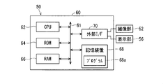
- FIG. 2 is a block diagram showing an electrical configuration of the inspection processing unit 60.
- the inspection processing unit 60 is configured by a general computer in which, for example, a CPU 62, a ROM 64, a RAM 66, a storage device 68, an external interface 70, and the like are interconnected via a bus line 61.
- the ROM 64 stores basic programs and the like, and the RAM 66 is used as a work area when the CPU 62 performs processing.
- the imaging unit 52 and the display unit 56 are connected to the external interface 70, whereby imaging data obtained by the imaging unit 52 is taken in for inspection processing, and the processing result is displayed on the display unit 56.
- the storage device 68 stores a program 68a for performing inspection processing, and the CPU 62 as the main control unit performs arithmetic processing according to the procedure described in the program 68a, so that the wire harness inspection device 50 can be operated. Each function is realized.
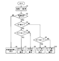
- FIG. 3 is a flowchart showing the determination process of the inspection processing unit 60.
- the inspection processing unit 60 acquires image data of the inspection target portion through the imaging unit 52 in step S ⁇ b> 1.
- the image data is subjected to processing such as background deletion, correction of the inclination of the inspection target portion, and gray scale, as necessary.
- step S2 the presence or absence of the exterior part 30 is determined.
- a processing example for determining the presence or absence of the exterior component 30 will be described later. If it is determined in step S2 that there is no exterior component 30, the process proceeds to step S6, and a message indicating that there is no exterior component 30 is displayed on the display unit 56. If it is determined in step S2 that the exterior component 30 is present, the process proceeds to step S3.
- step S3 the presence / absence of a corrugated tube (abbreviated as COT in FIG. 3) as the exterior component 30 is determined.
- COT corrugated tube
- a processing example for determining the presence or absence of the corrugated tube will be described later. If it is determined that there is a corrugated tube, the process proceeds to step S4.
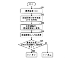
- step S4 it is determined whether or not the adhesive tape is wound around the corrugated tube by half-wrapping. An example of this determination process will be described later. If it is determined that there is a tape, the process proceeds to step S7, and the display unit 56 displays that the corrugated tube is present and the tape is present. If it is determined that there is no tape, the process proceeds to step S8, and the display unit 56 displays that there is a corrugated tube and no tape.
- step S5 it is determined whether or not the adhesive tape is wound around the non-corrugated tube (shown as a tube in FIG. 3) as the exterior component 30 by half-wrapping. An example of this determination process will be described later. If it is determined that there is a tape, the process proceeds to step S9, and the display unit 56 displays that the tube is present and the tape is present. If it is determined that there is no tape, the process proceeds to step S10, and the display unit 56 displays that there is a tube and no tape.
- steps S6 to S10 in addition to or instead of displaying whether or not the exterior component 30 is a corrugated tube and whether or not there is a tape, the exterior component 30 to be exteriorized on the inspection target portion is displayed.
- the type and presence / absence of a tape may be registered in advance, and a pass determination may be notified when the processing determination result matches the registered content, and a failure determination may be notified when there is a mismatch.
- the notification may be performed by display or sound on the display unit 56.
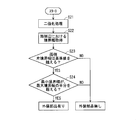
- FIG. 4 is a flowchart showing an example of processing for determining the presence or absence of the exterior part 30 in step S2.
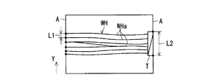
- FIG. 5 is an example showing an image when the exterior component 30 is not sheathed on the bundle of electric wires WHa of the inspection target portion
- FIG. 6 is a partial binding adhesive tape T wound around the bundle of the electric wires WHa.
- FIG. 7 is an example showing an image when the corrugated tube 32 is sheathed on the bundle of the same wire WHa
- FIG. 8 is a non-corrugated tube on the bundle of the same wire WHa. It is an example which shows an image in case the tube 34 as is exteriorized.
- the extension direction of the electric wire WHa may be described as the X direction, and the direction orthogonal thereto may be expressed as the Y direction.
- step S21 the binarization process is performed on the imaging data with reference to a predetermined luminance value.
- edge extraction processing or the like By performing edge extraction processing or the like on the binarized image, each boundary line of the electric wire WHa, the adhesive tape T, the corrugated tube 32, the exterior component 30, and the like is extracted.
- step S22 the position of the boundary on both sides A of the image data is recognized, and the boundary width in the direction along each side A is acquired.
- the boundary width L1 is obtained as the boundary width L1.
- the boundary width is acquired as a relatively small value corresponding to the diameter of the electric wires of several wires.
- the side A of the image data is shown in FIG.
- the corrugated tube 32 when the corrugated tube 32 is present, as shown in FIG. 8, when the tube 34 is present, the diameter of the bundle of the wires WHa or a value larger than that is acquired as the boundary width.
- This boundary width is a large value in the side A as compared with the case where the electric wire WHa exists.
- step S23 it is determined whether or not the boundary widths L1 and L2 on both sides A exceed the reference value.
- the reference value is a value set in advance that is speculatively and experimentally determined as a value that can distinguish the boundary width L1 and the boundary width L2.
- step S3 when it is determined that the boundary widths L1 and L2 on both sides A do not exceed the reference value, it is determined that the exterior component 30 is not present. As a result, as shown in FIG. 5, when the boundary width L1 on both sides A is small, it is determined that there is no exterior component 30.
- step S23 if it is determined in step S23 that the boundary widths L1 and L2 of both sides A do not exceed the reference value, the process proceeds to step S24.
- step S24 it is determined whether or not the minimum boundary widths L1 and L2 exceed half of the maximum boundary widths L1 and L2. If it is determined that the minimum boundary widths L1 and L2 do not exceed, it is determined that there is no exterior part 30.
- a plurality of boundaries L1 are obtained because there are a number of boundaries on the side.
- the minimum boundary width and the maximum boundary width are obtained from the plurality of boundary widths L1 and L2 acquired on both sides A. Then, it is determined whether or not the minimum boundary widths L1 and L2 exceed half of the maximum boundary widths L1 and L2. If NO, it is determined that there is no exterior part 30. For example, as shown in FIG. 6, a plurality of electric wires WHa are present on one side A, a relatively small boundary width L1 is obtained, and a binding adhesive tape T is wound on the other side A.
- the minimum boundary widths L1 and L2 do not exceed half of the maximum boundary widths L1 and L2, that is, there is no exterior part 30. Is done.
- the process may proceed to either YES or NO. Further, the minimum boundary width may be compared with a predetermined ratio value smaller than the maximum boundary width.
- step S24 when it is determined that the minimum boundary widths L1 and L2 exceed half of the maximum boundary widths L1 and L2, it is determined that the exterior component 30 is present.
- the corrugated tube 32 is a part molded by a circulation mold or the like, the outer shape of the corrugated tube 32 exhibits a known periodicity in the extending direction. For this reason, when the corrugated tube 32 is included in the inspection target portion, the feature amount of the image in the extending direction of the electric wire WHa shows periodicity according to the periodicity of the corrugated tube 32. Therefore, it is determined whether or not the corrugated tube 32 is packaged as an exterior component based on the periodicity of the feature amount of the image in the extending direction of the electric wire WHa in the imaging data and the periodicity of the shape of the corrugated tube.
- the feature amount of the image in the extending direction of the electric wire WHa includes the width of the exterior component 30 reflected as an image, the luminance integrated value in the width direction of the exterior component 30, the standard deviation integrated value in the width direction of the exterior component 30, and the like.
- Various elements obtained based on the periodicity of the shape of the tube are conceivable.
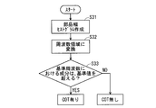
- FIG. 9 is a flowchart showing the process of determining the presence or absence of the corrugated tube 32 using the width of the exterior part 30 as a feature amount in step S3.
- the width of the large diameter portion 32a of the corrugated tube 32 is larger than the width of the small diameter portion 32b of the corrugated tube 32, the width in the extending direction of the electric wire WHa is the same as that of the large diameter portion 32a of the corrugated tube 32.
- the presence / absence of the corrugated tube 32 is determined based on the change in accordance with the periodicity with the small diameter portion 32b.
- a component width histogram is created. That is, in the imaging data obtained by imaging the inspection target portion, the width of the exterior component 30 (the extending direction) with respect to each discrete position along the extending direction of the electric wire WHa (the X direction in FIGS. 7 and 8). Y direction orthogonal to (see FIGS. 7 and 8).
- the width of the exterior component 30 can be obtained by sequentially obtaining edge intervals in the Y direction in an image obtained by binarizing imaging data.
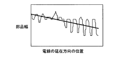
- the component width histogram in the case where the corrugated tube 32 is mounted has a large value in the portions of the large diameter portions 32a (see FIG. 7), and the portions of the small diameter portions 32b (see FIG. 7) shows the periodicity of a small value.
- the component width histogram when the tube 34 is mounted does not show a large periodic variation as shown in FIG. 12, for example.
- step S32 the component width histogram is converted into the frequency domain by performing pseudo frequency conversion (discrete Fourier transform). Then, when the corrugated tube 32 is externally mounted, as shown in FIG. 11, the frequency component becomes large at the reference frequency fs corresponding to the repetition period of the large diameter portion 32a and the small diameter portion 32b. On the other hand, when the tube 34 is externally mounted, as shown in FIG. 13, the frequency component does not become so large at the reference frequency fs according to the repetition period of the large diameter portion 32a and the small diameter portion 32b.
- pseudo frequency conversion discrete Fourier transform
- the frequency component exceeds the reference value at the reference frequency fs obtained by converting the repetition period of the large diameter portion 32a and the small diameter portion 32b into a frequency.
- This reference value is a value that is determined experimentally and empirically as a value indicating the periodicity according to the corrugated tube 32 and is set in advance.
- the frequency component exceeds the reference value at the reference frequency fs (see FIG. 11)
- it is determined that the exterior component 30 is the corrugated tube 32.
- the frequency component does not exceed the reference value at the reference frequency fs (see FIG. 13)
- the exterior component 30 is not the corrugated tube 32 (here, the tube 34).
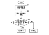
- FIG. 14 is a flowchart showing the process of determining the presence or absence of the corrugated tube 32 using the integrated luminance value of the exterior component 30 as a feature amount in step S3.
- the corrugated tube 32 when the corrugated tube 32 is illuminated, the large-diameter portion 32a is exposed to light, but the small-diameter portion 32b is not easily exposed to light, so the luminance in the extending direction of the electric wire WHa
- the presence or absence of the corrugated tube 32 is determined based on the value changing according to the periodicity between the large diameter portion 32a and the small diameter portion 32b of the corrugated tube 32.
- a luminance integrated value histogram is created. That is, in the data obtained by converting the imaging data obtained by imaging the inspection target portion into gray scale, the exterior component 30 is in each discrete position along the extending direction of the electric wire WHa (the X direction in FIGS. 7 and 8). An integrated luminance value is obtained in the width direction (Y direction orthogonal to the extending direction, see FIGS. 7 and 8).
- the luminance integrated value histogram has a large value in each large diameter portion 32a (see FIG. 7), for example, as shown in FIG. 15, and each thin diameter portion 32b ( The periodicity of a small value is shown in FIG.
- the luminance integrated value histogram does not show a large periodic fluctuation.
- step S42 the luminance integrated value histogram is converted into a frequency domain by performing pseudo frequency conversion (discrete Fourier transform). Then, when the corrugated tube 32 is packaged, as shown in FIG. 16, the frequency component becomes large at the reference frequency fs corresponding to the repetition period of the large diameter portion 32a and the small diameter portion 32b. On the other hand, when the tube 34 is externally mounted, the frequency component does not become so large at the reference frequency fs corresponding to the repetition period of the large diameter portion 32a and the small diameter portion 32b.
- pseudo frequency conversion discrete Fourier transform
- the frequency component exceeds the reference value at the reference frequency fs obtained by converting the repetition period of the large diameter portion 32a and the small diameter portion 32b into a frequency.
- This reference value is a value that is determined experimentally and empirically as a value indicating the periodicity according to the corrugated tube 32 and is set in advance.
- the frequency component exceeds the reference value at the reference frequency fs (see FIG. 16)
- the reference frequency fs when it is determined that the frequency component does not exceed the reference value at the reference frequency fs, it is determined that the exterior component 30 is not the corrugated tube 32 (here, the tube 34).
- the reference frequency fs when the frequency component is the same as the reference value, any determination may be made.
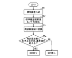
- FIG. 17 is a flowchart showing processing for determining whether or not the corrugated tube 32 is present in step S3 using the integrated value of the standard deviation of each pixel of the exterior component 30 as a feature amount.
- this processing when the corrugated tube 32 is illuminated, the way the light hits is different at the boundary portion between the large diameter portion 32a and the small diameter portion 32b.
- the presence / absence of the corrugated tube 32 is determined based on the change in accordance with the periodicity of the boundary portion between the large diameter portion 32a and the small diameter portion 32b.
- the standard deviation of the pixel of interest with respect to the surrounding pixels is used as an index value representing the variation of each pixel with respect to the surrounding image.
- step S51 the standard deviation filter process is performed on the data obtained by converting the imaging data obtained by imaging the inspection target portion into grayscale. Thereby, standard deviation image data in which each pixel is represented by a standard deviation is obtained.
- a standard deviation integrated value histogram is created based on the standard deviation image data. That is, in the standard deviation image data, for each discrete position along the extending direction of the electric wire WHa (X direction in FIGS. 7 and 8), the width direction of the exterior component 30 (with respect to the extending direction). The integrated value of the standard deviation in the orthogonal Y direction (see FIGS. 7 and 8) is obtained.
- the standard deviation integrated value histogram has a large value at the boundary portion (see FIG. 7) between the large diameter portion 32a and the small diameter portion 32b, for example, as shown in FIG. The periodicity which becomes a small value in the intermediate part of the diameter part 32a and the intermediate part of the small diameter part 32b is shown.
- the tube 34 is mounted, the standard deviation integrated value histogram does not show a large periodic fluctuation.
- step S53 the standard deviation integrated value histogram is converted into a frequency domain by performing pseudo frequency conversion (discrete Fourier transform). Then, when the corrugated tube 32 is externally mounted, as shown in FIG. 19, the frequency component becomes large at the reference frequency fs corresponding to the repetition period of the large diameter portion 32a and the small diameter portion 32b. On the other hand, when the tube 34 is externally mounted, the frequency component does not become so large at the reference frequency fs corresponding to the repetition period of the large diameter portion 32a and the small diameter portion 32b.
- pseudo frequency conversion discrete Fourier transform
- the frequency component exceeds the reference value at the reference frequency fs obtained by converting the repetition period of the large diameter portion 32a and the small diameter portion 32b into a frequency.
- This reference value is a value that is determined experimentally and empirically as a value indicating the periodicity according to the corrugated tube 32 and is set in advance. If it is determined that the frequency component exceeds the reference value at the reference frequency fs (see FIG. 19), it is determined that the exterior component 30 is the corrugated tube 32. On the other hand, when it is determined that the frequency component does not exceed the reference value at the reference frequency fs, it is determined that the exterior component 30 is not the corrugated tube 32 (here, the tube 34). When the frequency component at the reference frequency fs is the same as the reference value, any determination may be made.
- the determination processing for the presence / absence of each corrugated tube 32 may be used alone or in combination. For example, three determination processes may be performed, and the presence or absence of the corrugated tube 32 may be determined by majority decision. If different determination results are made as the three determination processes, error determination (undecidable) It may be entrusted.
- FIG. 20 is a flowchart showing an example of the process of step S4 for determining the presence or absence of the adhesive tape T when it is determined that the corrugated tube 32 is present.
- an index value representing the variation of each pixel with respect to the surrounding image is obtained based on the imaging data, the periodicity of the index value in the extending direction of the electric wire WHa is obtained, and the periodicity is indicated by the shape of the corrugated tube 32.
- the presence or absence of the adhesive tape T is determined using the standard deviation of each pixel of the exterior component 30 as a feature amount.
- step S61 the standard deviation filter process is performed on the data obtained by converting the imaging data obtained by imaging the inspection target portion into a gray scale. Thereby, standard deviation image data in which each pixel is represented by a standard deviation is obtained.
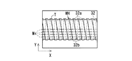
- a standard deviation histogram is created for each of a plurality of scanning lines based on the standard deviation image data. That is, the scanning lines M along the extending direction (X direction) of the electric wires WHa are set for the standard deviation image data (a part of the scanning lines M is shown in FIG. 21). A plurality of scanning lines M are preset at intervals in the width direction (Y direction) perpendicular to the extending direction of the electric wire WHa. Then, a standard deviation histogram is created for each scanning line M. When the adhesive tape T is spirally wound around the corrugated tube 32, the standard deviation histogram has a large value at the boundary portion (see FIG. 21) between the large diameter portion 32a and the small diameter portion 32b.
- the boundary portion appearing on the outer peripheral surface also has a large value.
- the standard deviation histogram has a large value at the boundary portion (see FIG. 21) between the large diameter portion 32a and the small diameter portion 32b.
- the periodicity which becomes a small value in the intermediate part of the part 32a and the intermediate part of the small diameter part 32b is shown.
- the standard deviation integrated value histogram is not generated because the boundary of the adhesive tape T appears obliquely and is difficult to process as characteristic data indicating the presence or absence of the adhesive tape T.
- the standard deviation histogram for each scanning line M is converted into a frequency domain by performing pseudo frequency conversion (discrete Fourier transform). Then, when the adhesive tape T is spirally wound around the sheathed corrugated tube 32, as shown in FIG. 22, at the reference frequency fs according to the repetition period of the large diameter portion 32a and the small diameter portion 32b, the frequency component And the frequency component also increases to some extent at other frequencies of the reference frequency fs.
- pseudo frequency conversion discrete Fourier transform
- S / N ratio conversion is performed for each scanning line M.
- the S / N ratio conversion is performed, for example, by determining the ratio between the signal component and the noise component by regarding the component of the reference frequency fs as a signal component and the other frequency components as noise components.
- the presence / absence of periodicity other than the reference frequency fs is determined. If it is determined that there is periodicity, it is determined that the adhesive tape T is present. If it is determined that there is no periodicity, it is determined that there is no adhesive tape T. Specifically, for example, when the adhesive tape T is spirally wound around the exterior corrugated tube 32, the frequency component is large at a frequency corresponding to the spiral winding of the adhesive tape T even at other frequencies of the reference frequency fs. Therefore, the noise component becomes large and the S / N ratio becomes relatively small.
- the S / N for each scanning line M is compared with a predetermined threshold value, and when there is even one S / N exceeding (or above) the threshold value, or a predetermined number is set. If it exceeds (or exceeds), it may be determined that there is periodicity other than the reference frequency fs, and otherwise, it may be determined that there is no periodicity other than the reference frequency fs.
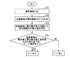
- FIG. 23 is a flowchart showing an example of the process of step S5 for determining the presence or absence of the adhesive tape T when it is determined that there is no corrugated tube 32 (with the tube 34).
- an index value representing the variation of each pixel with respect to the surrounding image is obtained based on the imaging data, the maximum value of the index value in the extending direction (X direction) of the electric wire WHa is obtained, and the extending direction of the electric wire WHa
- the minimum value of the index value within a predetermined range is obtained from the position where the maximum value is taken in the (X direction), and the presence or absence of the adhesive tape T tape is determined based on the comparison between the maximum value and the minimum value.
- the presence or absence of the boundary of the adhesive tape T is determined, and the presence or absence of the adhesive tape T is determined.
- step S71 standard deviation filter processing is performed on the data obtained by converting the imaging data obtained by imaging the inspection target portion into grayscale. Thereby, standard deviation image data in which each pixel is represented by a standard deviation is obtained.
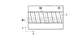
- a standard deviation histogram is created for each of a plurality of scanning lines based on the standard deviation image data. That is, scanning lines M along the extending direction (X direction) of the electric wires WHa are set for the standard deviation image data (a part of the scanning lines M is shown in FIG. 24). A plurality of scanning lines M are preset at intervals in the width direction (Y direction) perpendicular to the extending direction of the electric wire WHa. Then, as shown in FIG. 25, a standard deviation histogram is created for each scanning line M.
- the standard deviation histogram When the adhesive tape T is spirally wound around the tube 34, the standard deviation histogram has a large value at the position of one side of the adhesive tape T (side that spirals and appears outside), and is small at the other portions. Become. On the other hand, when the adhesive tape T is not spirally wound around the tube 34, the standard deviation histogram continues at a relatively small value.
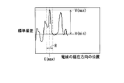
- the maximum value V (max) is obtained, and the position X (max) that takes the maximum value V (max) is obtained.
- the minimum value V (min) in the predetermined range R preset from the said position X (max) is specified.
- the predetermined range R is, for example, a range that is determined empirically and experimentally as a range in which the standard deviation can vary greatly at the side boundary of the adhesive tape T, and is set around the position X (max).
- the maximum value V (max) and the minimum value V (min) are compared for each scanning line M, and the presence or absence of the boundary of the adhesive tape T is determined based on the comparison result.
- the difference between the maximum value V (max) and the minimum value V (min) is obtained, and the difference is compared with a predetermined reference value.
- the predetermined reference value is a value that is empirically and experimentally determined and preset as a difference in which the standard deviation may fluctuate at the side boundary of the adhesive tape T.
- the reference value is set as a proportional value such as half of the maximum value V (max), and may be a value that is relatively obtained each time, or may be set as an absolute value.
- the difference between the maximum value V (max) and the minimum value V (min) exceeds (or exceeds) a predetermined reference value, or exceeds a predetermined number set in advance. In (or above), it may be determined that the adhesive tape T is present, and otherwise, it may be determined that the adhesive tape T is absent.
- the presence / absence of the exterior component 30 is determined, and when the exterior component 30 is present, the exterior component 30 determines the corrugated tube 32 or the tube 34, and the exterior component 30 is the corrugated tube 32 or the tube 34.
- the presence or absence of the adhesive tape T can be determined, so that it can be determined whether or not the desired exterior component 30 is externally mounted on the wire harness WH.
- the inspection target portion of the wire harness WH is imaged to acquire imaging data, and the extension of the electric wire WHa is based on the imaging data.
- the periodicity of the feature amount of the image in the current direction is obtained, and it is determined whether or not the corrugated tube 32 is externally mounted as the external component 30 based on the periodicity and the periodicity indicated by the shape of the corrugated tube 32.
- the corrugated tube 32 is packaged as the exterior component 30, the image feature amount in the extending direction of the electric wire WHa exhibits a certain periodicity according to the uneven shape of the corrugated tube 32. For this reason, it can be determined whether or not the corrugated tube 32 is externally provided.
- the periodicity of the width of the outer shape of the portion included in the inspection target portion of the wire harness WH is obtained, and the periodicity of the width is a constant cycle according to the uneven shape of the corrugated tube 32 of the corrugated tube 32. Whether or not the corrugated tube 32 is externally covered can be determined on the basis of whether or not the property is exhibited.
- the periodicity of the luminance integrated value of the portion included in the inspection target portion of the wire harness WH is obtained, and the periodicity of the luminance integrated value corresponds to the uneven shape of the corrugated tube 32 of the corrugated tube 32. Based on whether or not a certain periodicity is exhibited, it can be determined whether or not the corrugated tube 32 is sheathed.
- an index value indicating a variation of each pixel with respect to the surrounding image (here, a standard deviation of each pixel with respect to the surrounding image) is obtained.
- This is integrated in the width direction of the wire harness WH, the periodicity of this value is obtained, and based on whether the periodicity shows a certain periodicity according to the uneven shape of the corrugated tube 32 of the corrugated tube 32. It can be determined whether or not the corrugated tube 32 is externally provided.
- the periodicity of an index value (in this case, the standard deviation of each pixel with respect to the peripheral image) representing the variation of each pixel with respect to the peripheral image is obtained based on the imaging data, and the electric wire Obtaining the periodicity of the index value in the extending direction of WHa and determining that the adhesive tape T is wound when the periodicity appears in addition to the periodicity indicated by the shape of the corrugated tube 32. it can.
- an index value indicating the variation of each pixel with respect to the surrounding image based on the imaging data here, the standard deviation of each pixel with respect to the surrounding image
- the maximum value V (max) of the index value in the extending direction of the electric wire WHa is calculated, and the minimum value V (within the predetermined range R from the position where the maximum value V (max) in the extending direction of the electric wire WHa is obtained. min) and based on the comparison between the maximum value V (max) and the minimum value V (min), the presence or absence of the adhesive tape T can be determined.
Landscapes
- Physics & Mathematics (AREA)
- General Physics & Mathematics (AREA)
- Health & Medical Sciences (AREA)
- Life Sciences & Earth Sciences (AREA)
- Chemical & Material Sciences (AREA)
- Analytical Chemistry (AREA)
- Biochemistry (AREA)
- General Health & Medical Sciences (AREA)
- Immunology (AREA)
- Pathology (AREA)
- Engineering & Computer Science (AREA)
- Manufacturing & Machinery (AREA)
- Investigating Materials By The Use Of Optical Means Adapted For Particular Applications (AREA)
- Length Measuring Devices By Optical Means (AREA)
- Insulated Conductors (AREA)
Abstract
コルゲートチューブが外装されているか否かを判別可能にする技術を提供することを目的とする。電線と、電線の周囲を覆う外装部品とを備えるワイヤーハーネスの検査方法であって、ワイヤーハーネスの検査対象部分を撮像し、撮像データを取得する撮像工程と、撮像データに基づいて電線の延在方向における画像の特徴量の周期性を求め、その周期性とコルゲートチューブの形状の周期性とに基づいて外装部品としてコルゲートチューブが外装されているか否かを判断する判断工程と、を備える。
Description
この発明は、ワイヤーハーネスにおける外装部品の判別を行うための技術に関する。
自動車等の車両に搭載されるワイヤーハーネスにおいて、電線の周囲を覆う外装部品を備えるものがある。
特許文献1に示されるように、電線の周囲を覆う外装部品としては、例えば、コルゲートチューブが採用される。
また、コルゲートチューブの他に、ゴムチューブ及びPVCシート等が電線の周囲を覆う外装部品として採用されることもある。
また、ワイヤーハーネスにおいて、電線がむき出しの状態、即ち、外装部品を備えないものもある。
ところで、その電線に装着されている外装部品の種類の確認作業は、作業者が視覚的に判断することで行われている。ここで、電線の外装部品の種類の確認作業を、画像検査によって行うことが望まれている。
しかしながら、コルゲートチューブとその他の外装部品(例えば、ゴムチューブ又はPVCシート等)とは、ともに似た色を有する場合等があり、画像検査によって、コルゲートチューブが外装されているか否かを判別することが困難である。
そこで、この発明は、コルゲートチューブが外装されているか否かを判別可能にする技術を提供することを目的とする。
上記課題を解決するため、第1の態様は、電線と、電線の周囲を覆う外装部品とを備えるワイヤーハーネスの検査方法であって、ワイヤーハーネスの検査対象部分を撮像し、撮像データを取得する撮像工程と、前記撮像データに基づいて電線の延在方向における画像の特徴量の周期性を求め、その周期性とコルゲートチューブの形状の周期性とに基づいて外装部品としてコルゲートチューブが外装されているか否かを判断する判断工程と、を備える。
第2の態様は、第1の態様に係るワイヤーハーネスの検査方法であって、電線の延在方向における画像の特徴量として、ワイヤーハーネスの外形状の幅を含むものである。
第3の態様は、第1又は第2の態様に係るワイヤーハーネスの検査方法であって、電線の延在方向における画像の特徴量として、ワイヤーハーネスの幅方向における輝度積算値を含むものである。
第4の態様は、第1から第3のいずれか1つの態様に係るワイヤーハーネスの検査方法であって、電線の延在方向における画像の特徴量として、周辺画素に対する各画素のばらつきを表す指標値を、ワイヤーハーネスの幅方向に積算した値を含むものである。
第5の態様は、第1から第4のいずれか1つの態様に係るワイヤーハーネスの検査方法であって、外装部品としてコルゲートチューブが外装されている場合に、前記撮像データに基づいて周辺画像に対する各画素のばらつきを表す指標値を求め、電線の延在方向における前記指標値の周期性を求め、その周期性が、コルゲートチューブの形状が示す周期性以外に現れているときに、テープが巻回されていると判断する第1テープ有無判断工程をさらに備えるものである。
第6の態様は、第1から第5のいずれか1つの態様に係るワイヤーハーネスの検査方法であって、外装部品として非コルゲートチューブが外装されている場合に、前記撮像データに基づいて周辺画像に対する各画素のばらつきを表す指標値を求め、電線の延在方向における前記指標値の最大値を求めると共に、電線の延在方向における前記最大値を取る位置から所定範囲内における前記指標値の最小値を求め、前記最大値と前記最小値との比較に基づいて、テープの有無を判断する第2テープ有無判断工程を備えるものである。
第7の態様に係るワイヤーハーネスの検査装置は、電線と、電線の周囲を覆う外装部品とを備えるワイヤーハーネスのうち検査対象部分を撮像し、撮像データを取得する撮像部と、前記撮像データに基づいて電線の延在方向における画像の特徴量の周期性を求め、その周期性とコルゲートチューブの形状の周期性とに基づいて外装部品としてコルゲートチューブが外装されているか否かを判断する判断部とを備える。
第1~第7の態様によると、ワイヤーハーネスの検査対象部分を撮像して撮像データを取得し、その撮像データに基づいて電線の延在方向における画像の特徴量の周期性を求め、その周期性とコルゲートチューブの形状の周期性とに基づいて外装部品としてコルゲートチューブが外装されているか否かを判断する。外装部品としてコルゲートチューブが外装されていれば、電線の延在方向における画像特徴は、コルゲートチューブの凹凸形状に応じた一定の周期性を示す。このため、コルゲートチューブが外装されているか否かを判別できる。
第2の態様によると、ワイヤーハーネスの外形状の幅の周期性に基づくことで、外装部品としてコルゲートチューブが外装されているか否かを判断することができる。
第3の態様によると、ワイヤーハーネスの幅方向における輝度積算値の周期性に基づくことで、外装部品としてコルゲートチューブが外装されているか否かを判断することができる。
第4の態様によると、周辺画素に対する各画素のばらつきを表す指標値を、ワイヤーハーネスの幅方向に積算した値の周期性に基づくことで、外装部品としてコルゲートチューブが外装されているか否かを判断することができる。
第5の態様によると、撮像データに基づいて周辺画像に対する各画素のばらつきを表す指標値を求め、電線の延在方向における指標値の周期性を求め、その周期性が、コルゲートチューブの形状が示す周期性以外に現れているときに、テープが巻回されていると判断することができる。
第6の態様によると、撮像データに基づいて周辺画像に対する各画素のばらつきを表す指標値を求め、電線の延在方向における前記指標値の最大値を求めると共に、電線の延在方向における前記最大値を取る位置から所定範囲内における前記指標値の最小値を求め、前記最大値と前記最小値との比較に基づいて、テープの有無を判断することができる。
以下、実施形態に係るワイヤーハーネスの検査方法及びワイヤーハーネス検査装置について説明する。
ワイヤーハーネスの検査方法は、ワイヤーハーネスを組立てるワイヤーハーネス組立図板において、ワイヤーハーネスが組立てられた状態で実施される。組立てられたワイヤーハーネスのうち外装部品が装着される部分を検査対象部分として撮像し、その撮像データから電線の延在方向における画像の特徴量の周期性を求め、その周期性とコルゲートチューブの形状が示す周期性とに基づいて、コルゲートチューブが外装されているか否かを判別する方法である。
図1は、ワイヤーハーネスの検査方法を実装したワイヤーハーネス検査装置50の説明図である。
ワイヤーハーネス組立図板20は、図板22と、当該図板22上に立設された複数の電線保持具24とを備える。電線保持具24は、ワイヤーハーネスWHを構成する電線を保持可能な形状、例えば、上端部がU字状に形成された部材である。電線保持具24は、図板22上におけるワイヤーハーネスWHの布線経路に沿って配設される。電線保持具24が立設される位置は、ワイヤーハーネスWHの端部、分岐部分等である。
ワイヤーハーネス組立図板20上に、複数の電線が所定の布線経路に沿って配設される。複数の電線は、ワイヤーハーネスWHの端部でコネクタ等を介して接続されている。複数の電線は、適宜箇所にて、粘着テープ、結束バンド等で結束されることで、車両等における布線形態に沿って適宜分岐する形態に組立てられる。このワイヤーハーネスWHは、車両等に組付けられ、車両における各種電気部品同士を電気的に接続する配線材として用いられる。
ワイヤーハーネスWHには、車両への固定用のクランプ部品、電線を外部から保護する外装部品30が外装される。
外装部品30は、ワイヤーハーネスWHを構成する電線の少なくとも一部の周囲を覆って当該電線を保護等するための部材である。外装部品30としては、コルゲートチューブ、及び、非コルゲートチューブであること想定される。コルゲートチューブは、太径部と当該太径部よりも径が小さい細径部とが交互に連続する樹脂製の筒状部材である。非コルゲートチューブとしては、同径部分が連続する樹脂製のチューブ、樹脂シートが筒状に曲げられたものであることが想定される。
なお、コルゲートチューブ及び非コルゲートチューブには、粘着テープがハーフラップ巻きされることもあり(幅方向の半分程度を重ねつつ螺旋状に巻く形態)、ここでは、そのようなテープの有無をも検査する。
ワイヤーハーネス検査装置50は、撮像部52と、検査処理ユニット60とを備える。
撮像部52は、イメージセンサ及びレンズ等によって構成されており、ワイヤーハーネス組立図板20上において、ワイヤーハーネスWHのうち外装部品30が外装されるべき部分を検査対象部分として撮像可能な位置及び姿勢で設けられている。この撮像部52により、当該検査対象部分を撮像した撮像データが取得される。撮像部52は、ワイヤーハーネスWHの一部を撮像するものであってもよいし、ワイヤーハーネスWHの全体を撮像し、その一部の画像を切り取って、検査用の画像として用いるものであってもよい。また、撮像部52は、固定位置に設けられていてもよいし、ロボットハンド等に支持され、適宜、所定箇所を撮像すべく移動してもよい。
好ましくは、撮像部52により撮像される箇所を照明する照明部54が設けられる。
検査処理ユニット60は、撮像部52で取得された撮像データに基づいて電線の延在方向における画像の特徴量の周期性を求め、その周期性とコルゲートチューブの形状の周期性とに基づいて外装部品としてコルゲートチューブが外装されているか否かを判断可能に構成されている。
上記検査処理ユニット60には、液晶表示装置等の表示部56が接続され、検査処理ユニット60における判断結果が当該表示部56に表示される。
図2は、検査処理ユニット60の電気的構成を示すブロック図である。検査処理ユニット60は、例えば、CPU62、ROM64、RAM66、記憶装置68、外部インターフェース70等がバスライン61を介して相互接続された一般的なコンピュータによって構成されている。ROM64は、基本プログラム等を格納しておる、RAM66は、CPU62が処理を行う際の作業領域として供される。撮像部52、表示部56は、外部インターフェース70に接続されており、これにより、撮像部52で得られた撮像データが検査処理用に取込まれ、また、処理結果が表示部56に表示される。
記憶装置68には、検査処理を行うためのプログラム68aが格納されており、主制御部としてのCPU62が、当該プログラム68aに記述された手順に従って演算処理を行うことにより、ワイヤーハーネス検査装置50の各機能が実現される。
図3は検査処理ユニット60の判断処理を示すフローチャートである。
ワイヤーハーネス組立図板20でワイヤーハーネスWHが組立てられた状態で、ステップS1において、検査処理ユニット60は、撮像部52を通じて検査対象部分の画像データを取得する。画像データに対しては、必要に応じて、背景削除、検査対象箇所の傾き補正、グレースケール化等の処理が行われる。
次ステップS2において、外装部品30の有無が判定される。外装部品30の有無を判定する処理例については後述する。ステップS2において、外装部品30が無いと判定されると、ステップS6に進み、外装部品30が無い旨を表示部56に表示する。ステップS2において、外装部品30が有ると判定されると、ステップS3に進む。
ステップS3では、外装部品30としてのコルゲートチューブ(図3ではCOTと省略)の有無を判定する。コルゲートチューブの有無を判定する処理例については後述する。コルゲートチューブ有りと判定されると、ステップS4に進む。
ステップS4では、コルゲートチューブに粘着テープがハーフラップ巻きで巻回されているか否かを判定する。この判定処理例については後述する。テープ有りと判定されると、ステップS7に進み、コルゲートチューブ有りで、かつ、テープ有りである旨を表示部56に表示する。テープが無いと判定されると、ステップS8に進み、コルゲートチューブ有りで、かつ、テープ無しである旨を表示部56に表示する。
ステップS3において、コルゲートチューブが無いと判定されると、ステップS5に進む。ステップS5では、外装部品30としての非コルゲートチューブ(図3ではチューブと表記)に粘着テープがハーフラップ巻きで巻回されているか否かを判定する。この判定処理例については後述する。テープ有りと判定されると、ステップS9に進み、チューブ有りで、かつ、テープ有りである旨を表示部56に表示する。テープが無いと判定されると、ステップS10に進み、チューブ有りで、かつ、テープ無しである旨を表示部56に表示する。
なお、ステップS6~S10において、外装部品30がコルゲートチューブであるかどうか、テープがあるかどうかを表示することに加えて、又は、代えて、当該検査対象部分に外装されるべき外装部品30の種類及びテープの有無を予め登録しておき、前記処理判断結果が当該登録内容と一致する場合に合格判定を報知し、不一致である場合に不合格判定を報知するようにしてもよい。報知は、表示部56における表示又は音等によって行うとよい。
図4はステップS2において、外装部品30の有無を判定する処理例を示すフローチャートである。図5は検査対象部分の電線WHaの束に外装部品30が外装されていない場合の画像を示す例であり、図6は同電線WHaの束に部分的な結束用の粘着テープTが巻回されている場合の画像を示す例であり、図7は同電線WHaの束にコルゲートチューブ32が外装されている場合の画像を示す例であり、図8は同電線WHaの束に非コルゲートチューブとしてのチューブ34が外装されている場合の画像を示す例である。なお、各図において、電線WHaの延在方向をX方向、これに直交する方向をY方向として表記している場合がある。
ステップS21において、撮像データに対して所定の輝度値を基準として2値化処理がなされる。2値化画像に対してエッジ抽出処理等を行うことによって、電線WHa、粘着テープT、コルゲートチューブ32,外装部品30等の各境界線が抽出される。
ステップS22において、画像データの両側辺Aにおける境界の位置を認識し、各側辺Aに沿った方向における境界幅が取得される。
例えば、図5又は図6に示すように、画像データのいずれかの側辺Aにおいて、電線WHaが存在する場合には、境界幅L1として、各電線WHaの直径又はそれ以下の値が取得される。電線の色によっては、一部の電線間の境界が表れないこともあり得るが、その場合でも、境界幅は数本分程度の電線の直径に応じた比較的小さい値として取得される。
また、図6に示すように、画像データの側辺Aに、電線WHaの束に部分的に巻付けられた粘着テープTが存在する場合、図7に示すように、画像データの側辺Aにコルゲートチューブ32が存在する場合、図8に示すように、チューブ34が存在する場合、境界幅として、電線WHaの束の直径又はそれ以上の値が取得される。この境界幅は、側辺Aにおいて、電線WHaが存在する場合と比較して、大きい値となる。
次ステップS23において、両側辺Aにおける境界幅L1、L2が基準値を超えるか否かが判定される。基準値は、上記境界幅L1と境界幅L2とを区別し得る値として推論的、実験的に決定され、事前に設定された値である。境界幅L1、L2が基準値と同じである場合、YES、NOのいずれに判定されてもよい。ステップS3において、両側辺Aにおける境界幅L1、L2が基準値を超えないと判定された場合、外装部品30は無しと判定される。これにより、図5に示すように、両側辺Aにおける境界幅L1が小さい場合には、外装部品30は無いと判定されることになる。
一方、ステップS23において、両側辺Aの境界幅L1、L2が基準値を超えないと判定された場合、ステップS24に進む。ステップS24では、最小の境界幅L1、L2が、最大の境界幅L1、L2の半分を超えるか否かが判定され、越えないと判定されると、外装部品30は無いと判定される。
例えば、ある側辺Aにおいて、複数の電線WHaが存在する場合、当該側辺には多数の境界が存在するため、複数の境界幅L1が取得される。両方の側辺Aにおいて取得された複数の境界幅L1、L2から最小となる境界幅と最大となる境界幅とを求める。そして、最小の境界幅L1、L2が、最大の境界幅L1、L2の半分を超えるか否かが判定され、NOと判定されると、外装部品30は無いと判定される。例えば、図6に示すように、一方の側辺Aにおいて複数の電線WHaが存在し、比較的小さい境界幅L1が取得され、かつ、他方の側辺Aにおいて結束用の粘着テープTが巻回され、比較的大きい境界幅L2が取得されているような場合には、最小の境界幅L1、L2が、最大の境界幅L1、L2の半分を超えない、つまり、外装部品30は無いと判定される。なお、最小の境界幅L1、L2が、最大の境界幅L1、L2の半分と同じである場合、YES、NOのいずれに進んでもよい。また、最小の境界幅を、最大の境界幅より小さい所定割合の値と比較してもよい。
ステップS24において、最小の境界幅L1、L2が、最大の境界幅L1、L2の半分を超えると判定された場合、外装部品30は有りと判定される。
例えば、図7に示すように、両側辺Aにおいてコルゲートチューブ32が存在している場合、及び、図8に示すように、両側辺Aにおいてチューブ34が存在している場合、両方の側辺Aにおける境界幅L2の差は大きくないため、最小の境界幅L1、L2は、最大の境界幅L1、L2の半分を超えず、外装部品30は有りと判定される。
これにより、検査対象部分における外装部品30の有無が判定される。
ステップS3においてコルゲートチューブ32の有無を判定する処理について説明する。コルゲートチューブ32は、循環金型等で成形される部品であるため、コルゲートチューブ32の外形状はその延在方向において既知の周期性を示す。このため、検査対象部分においてコルゲートチューブ32が含まれていると、電線WHaの延在方向における画像の特徴量は、コルゲートチューブ32の周期性に応じた周期性を示す。そこで、撮像データにおける電線WHaの延在方向における画像の特徴量の周期性と、コルゲートチューブの形状の周期性とに基づいて外装部品としてコルゲートチューブ32が外装されているか否かを判断する。電線WHaの延在方向における画像の特徴量としては、画像として映り込んだ外装部品30の幅、外装部品30の幅方向における輝度積算値、外装部品30の幅方向における標準偏差積算値等、コルゲートチューブの形状の周期性に基づいて得られる各種要素が考えられる。
以下、各場合についてより具体的に説明する。
図9はステップS3において、外装部品30の幅を特徴量としてコルゲートチューブ32の有無を判定する処理を示すフローチャートである。本処理では、コルゲートチューブ32の太径部32aの幅は、コルゲートチューブ32の細径部32bの幅より大きいことから、電線WHaの延在方向における幅は、コルゲートチューブ32の太径部32aと細径部32bとの周期性に応じて変化することに基づいて、コルゲートチューブ32の有無を判定する。
ステップS31において、部品幅ヒストグラムを作成する。すなわち、検査対象部分を撮像した撮像データにおいて、電線WHaの延在方向(図7及び図8のX方向)に沿った離散的な各位置に対して、外装部品30の幅(当該延在方向に対して直交するY方向、図7及び図8参照)を求める。外装部品30の幅は、撮像データを2値化した画像においてY方向のエッジ間隔を逐次求めること等によって得ることができる。コルゲートチューブ32が外装されている場合の部品幅ヒストグラムは、例えば、図10に示すように、各太径部32aの部分(図7参照)で大きな値となり、各細径部32bの部分(図7参照)で小さな値となる周期性を示す。これに対して、チューブ34が外装されている場合の部品幅ヒストグラムは、例えば、図12に示すように、大きな周期的変動を示さない。
次に、ステップS32において、上記部品幅ヒストグラムを、擬似周波数変換(離散フーリエ変換)して、周波数領域に変換する。すると、コルゲートチューブ32が外装されている場合、図11に示すように、太径部32a及び細径部32bの繰り返し周期に応じた基準周波数fsで、周波数成分が大きくなる。これに対して、チューブ34が外装されている場合、図13に示すように、太径部32a及び細径部32bの繰り返し周期に応じた基準周波数fsでは、周波数成分はそれ程大きくならない。
次ステップS33において、太径部32a及び細径部32bの繰り返し周期を周波数に換算した基準周波数fsにおいて、周波数成分が基準値を超えるか否かが判定される。この基準値は、コルゲートチューブ32に応じた周期性を示す値として実験的、経験的に求められ、予め設定された値である。基準周波数fsにおいて、周波数成分が基準値を超えていると判定されると(図11参照)、外装部品30がコルゲートチューブ32であると判定される。一方、基準周波数fsにおいて、周波数成分が基準値を超えていないと判定されると(図13参照)、外装部品30はコルゲートチューブ32ではない(ここでは、チューブ34である)と判定される。基準周波数fsにおいて、周波数成分と基準値とが同じである場合、いずれに判定してもよい。
図14はステップS3において、外装部品30の輝度積算値を特徴量としてコルゲートチューブ32の有無を判定する処理を示すフローチャートである。本処理では、コルゲートチューブ32に照明を当てた場合等には、太径部32aには光が当たるが、細径部32bでは凹んで光が当たり難いことから、電線WHaの延在方向における輝度値が、コルゲートチューブ32の太径部32aと細径部32bとの周期性に応じて変化することに基づいて、コルゲートチューブ32の有無を判定する。
ステップS41において、輝度積算値ヒストグラムを作成する。すなわち、検査対象部分を撮像した撮像データをグレースケール化したデータにおいて、電線WHaの延在方向(図7及び図8のX方向)に沿った離散的な各位置に対して、外装部品30の幅方向(当該延在方向に対して直交するY方向、図7及び図8参照)における輝度の積算値を求める。コルゲートチューブ32が外装されている場合、輝度積算値ヒストグラムは、例えば、図15に示すように、各太径部32aの部分(図7参照)で大きな値となり、各細径部32bの部分(図7参照)で小さな値となる周期性を示す。これに対して、チューブ34が外装されている場合、輝度積算値ヒストグラムは、大きな周期的変動を示さない。
次に、ステップS42において、上記輝度積算値ヒストグラムを、擬似周波数変換(離散フーリエ変換)して、周波数領域に変換する。すると、コルゲートチューブ32が外装されている場合、図16に示すように、太径部32a及び細径部32bの繰り返し周期に応じた基準周波数fsで、周波数成分が大きくなる。これに対して、チューブ34が外装されている場合、太径部32a及び細径部32bの繰り返し周期に応じた基準周波数fsでは、周波数成分はそれ程大きくならない。
次ステップS43において、太径部32a及び細径部32bの繰り返し周期を周波数に変換した基準周波数fsにおいて、周波数成分が基準値を超えるか否かが判定される。この基準値は、コルゲートチューブ32に応じた周期性を示す値として実験的、経験的に求められ、予め設定された値である。基準周波数fsにおいて、周波数成分が基準値を超えていると判定されると(図16参照)、外装部品30がコルゲートチューブ32であると判定される。一方、基準周波数fsにおいて、周波数成分が基準値を超えていないと判定されると、外装部品30はコルゲートチューブ32ではない(ここでは、チューブ34である)と判定される。基準周波数fsにおいて、周波数成分が基準値と同じである場合、いずれに判定してもよい。
図17はステップS3において、外装部品30の各画素の標準偏差の積算値を特徴量としてコルゲートチューブ32の有無を判定する処理を示すフローチャートである。本処理では、コルゲートチューブ32に照明を当てた場合等には、太径部32aと細径部32bとの境界部分で光の当たり方が異なることから、ある注目画素の周辺画素に対するばらつきは、太径部32aと細径部32bとの境界部分の周期性に応じて変化することに基づいて、コルゲートチューブ32の有無を判定する。ここでは、周辺画像に対する各画素のばらつきを表す指標値として、周辺画素に対する注目画素の標準偏差を用いた例を説明する。
ステップS51において、検査対象部分を撮像した撮像データをグレースケール化したデータに対して、標準偏差フィルタ処理を施す。これにより、各画素が標準偏差で表された標準偏差画像データが得られる。
次ステップS52において、標準偏差画像データに基づいて、標準偏差積算値ヒストグラムを作成する。すなわち、標準偏差画像データにおいて、電線WHaの延在方向(図7及び図8のX方向)に沿った離散的な各位置に対して、外装部品30の幅方向(当該延在方向に対して直交するY方向、図7及び図8参照)における標準偏差の積算値を求める。コルゲートチューブ32が外装されている場合、標準偏差積算値ヒストグラムは、例えば、図18に示すように、太径部32aと細径部32bとの境界部分(図7参照)で大きな値となり、太径部32aの中間部及び細径部32bの中間部で小さな値となる周期性を示す。これに対して、チューブ34が外装されている場合、標準偏差積算値ヒストグラムは、大きな周期的変動を示さない。
次に、ステップS53において、上記標準偏差積算値ヒストグラムを、擬似周波数変換(離散フーリエ変換)して、周波数領域に変換する。すると、コルゲートチューブ32が外装されている場合、図19に示すように、太径部32a及び細径部32bの繰り返し周期に応じた基準周波数fsで、周波数成分が大きくなる。これに対して、チューブ34が外装されている場合、太径部32a及び細径部32bの繰り返し周期に応じた基準周波数fsでは、周波数成分はそれ程大きくならない。
次ステップS54において、太径部32a及び細径部32bの繰り返し周期を周波数に変換した基準周波数fsにおいて、周波数成分が基準値を超えるか否かが判定される。この基準値は、コルゲートチューブ32に応じた周期性を示す値として実験的、経験的に求められ、予め設定された値である。基準周波数fsにおいて、周波数成分が基準値を超えていると判定されると(図19参照)、外装部品30がコルゲートチューブ32であると判定される。一方、基準周波数fsにおいて、周波数成分が基準値を超えていないと判定されると、外装部品30はコルゲートチューブ32ではない(ここでは、チューブ34である)と判定される。基準周波数fsにおける周波数成分が基準値と同じである場合、いずれに判定してもよい。
なお、上記各処理において、コルゲートチューブ32に粘着テープTが螺旋巻きされている場合であっても、粘着テープTの表面形状には、コルゲートチューブ32の表面形状が表れるため、コルゲートチューブ32の有無を判定できる。また、チューブ34に粘着テープTが螺旋巻されている場合であっても、粘着テープTが示す周期性は、コルゲートチューブ32の形状が示す周期性とは異なるため、この場合にも、コルゲートチューブ32の有無を判定できる。
上記各コルゲートチューブ32の有無の判断処理は、単独で用いられてもよいし、複合して用いられてもよい。例えば、3つの判断処理を行い、多数決でコルゲートチューブ32の有無を判断してもよし、3つの判断処理として異なる判断結果がなされた場合には、エラー処理(判断不能)として、人による判断に委ねるようにしてもよい。
図20は、コルゲートチューブ32が有ると判定された場合において、粘着テープTの有無を判定するステップS4の処理の一例を示すフローチャートである。本処理では、撮像データに基づいて周辺画像に対する各画素のばらつきを表す指標値を求め、電線WHaの延在方向における指標値の周期性を求め、その周期性が、コルゲートチューブ32の形状が示す周期性以外に現れているときに、粘着テープTが巻回されていると判断する。ここでは、外装部品30の各画素の標準偏差を特徴量として粘着テープTの有無を判定する。
ステップS61において、検査対象部分を撮像した撮像データをグレースケール化したデータに対して、標準偏差フィルタ処理を施す。これにより、各画素が標準偏差で表された標準偏差画像データが得られる。
次ステップS62において、標準偏差画像データに基づいて、複数の走査線毎に標準偏差ヒストグラムを作成する。すなわち、標準偏差画像データに対して電線WHaの延在方向(X方向)に沿った走査線Mが設定される(図21において一部の走査線Mを図示)。走査線Mは、電線WHaの延在方向に対して直交する幅方向(Y方向)において間隔をあけて複数事前設定されている。そして、走査線M毎に、標準偏差ヒストグラムを作成する。コルゲートチューブ32に粘着テープTが螺旋巻きされている場合、標準偏差ヒストグラムは、太径部32aと細径部32bとの境界部分(図21参照)で大きな値となり、さらに、粘着テープTのうち外周面に表れる境界部分でもある程度大きな値となる。これに対して、コルゲートチューブ32に粘着テープTが螺旋巻きされていない場合、標準偏差ヒストグラムは、太径部32aと細径部32bとの境界部分(図21参照)で大きな値となり、太径部32aの中間部及び細径部32bの中間部で小さな値となる周期性を示す。
なお、上記のように、標準偏差積算値ヒストグラムを生成しないのは、粘着テープTの境界が斜めに表れるため、粘着テープTの有無を示す特徴的なデータとして処理し難いからである。
次ステップS63において、走査線M毎の上記標準偏差ヒストグラムを、擬似周波数変換(離散フーリエ変換)して、周波数領域に変換する。すると、外装されたコルゲートチューブ32に、粘着テープTが螺旋巻きされている場合、図22に示すように、太径部32a及び細径部32bの繰り返し周期に応じた基準周波数fsで、周波数成分が大きくなると共に、当該基準周波数fsの他の周波数でも、周波数成分がある程度大きくなる。
次ステップS64において、走査線M毎に、S/N比換算を行う。S/N比換算は、例えば、基準周波数fsの成分を信号成分、その他の各周波数の成分を雑音成分と捉えて、信号成分と雑音成分との比を求めることにより行う。
次ステップS65において、走査線M毎のS/N比に基づいて、基準周波数fs以外での周期性の有無を判定し、周期性が有ると判定されると、粘着テープTが有ると判定され、周期性が無いと判定されると、粘着テープTは無いと判定される。具体的には、例えば、外装されたコルゲートチューブ32に、粘着テープTが螺旋巻きされている場合、基準周波数fsの他の周波数でも、粘着テープTの螺旋巻きに応じた周波数で周波数成分が大きくなるため、ノイズ成分が大きくなって、S/N比は比較的小さくなる。これに対して、外装されたコルゲートチューブ32に、粘着テープTが螺旋巻きされていない場合、基準周波数fsの他の周波数では周波数成分が小さくなるため、ノイズ成分が小さくなり、S/N比は大きくなる。そこで、走査線M毎のS/Nを、予め設定された所定の閾値と比較し、閾値を超える(又は以上)S/Nが一つでも存在する場合、或いは、予め設定された所定数を越える(又は以上)場合に、基準周波数fs以外での周期性が有ると判定し、それ以外の場合を、基準周波数fs以外での周期性が無いと判定すればよい。
図23は、コルゲートチューブ32が無いと判定された場合(チューブ34有り)において、粘着テープTの有無を判定するステップS5の処理の一例を示すフローチャートである。本処理では、撮像データに基づいて周辺画像に対する各画素のばらつきを表す指標値を求め、電線WHaの延在方向(X方向)における前記指標値の最大値を求めると共に、電線WHaの延在方向(X方向)における最大値を取る位置から所定範囲内における指標値の最小値を求め、最大値と最小値との比較に基づいて、粘着テープTテープの有無を判断する。ここでは、外装部品30の各画素の標準偏差の最大値と最小値との比較に基づいて、粘着テープTの境界の有無を判断して、粘着テープTの有無を判定する。
ステップS71において、検査対象部分を撮像した撮像データをグレースケール化したデータに対して、標準偏差フィルタ処理を施す。これにより、各画素が標準偏差で表された標準偏差画像データが得られる。
次ステップS72において、標準偏差画像データに基づいて、複数の走査線毎に標準偏差ヒストグラムを作成する。すなわち、標準偏差画像データに対して電線WHaの延在方向(X方向)に沿った走査線Mが設定される(図24において一部の走査線Mを図示)。走査線Mは、電線WHaの延在方向に対して直交する幅方向(Y方向)において間隔をあけて複数事前設定されている。そして、図25に示すように、走査線M毎に、標準偏差ヒストグラムを作成する。チューブ34に粘着テープTが螺旋巻きされている場合、標準偏差ヒストグラムは、粘着テープTの一側部(螺旋巻され外側に現れている側部)の位置で大きな値となり、その他の部分では小さくなる。これに対して、チューブ34に粘着テープTが螺旋巻きされていない場合、標準偏差ヒストグラムは、比較的小さい値で連続する。
次ステップS73において、走査線M毎の上記標準偏差ヒストグラムにおいて、最大値V(max)を求めると共に、当該最大値V(max)を取る位置X(max)を求める。そして、当該位置X(max)から予め設定された所定範囲R内の最小値V(min)を特定する。所定範囲Rは、例えば、粘着テープTの側部の境界で標準偏差が大きく変動し得る範囲として、経験的、実験的に決定され、位置X(max)を中心として設定される範囲である。
次ステップS74において、走査線M毎に、上記最大値V(max)と最小値V(min)とを比較し、比較結果に基づいて粘着テープTの境界の有無を判断する。
例えば、走査線M毎に、最大値V(max)と最小値V(min)との差を求め、当該差を所定の基準値と比較する。所定の基準値は、粘着テープTの側部の境界で標準偏差が変動し得る差として、経験的、実験的に決定され、事前設定される値である。基準値は、最大値V(max)の半分等の割合的な値として設定され、都度相対的に求められる値であってもよいし、絶対的な値として設定されていてもよい。そして、最大値V(max)と最小値V(min)との差が所定の基準値を越える(又は以上)である場合が1つでも存在する場合、或いは、予め設定された所定数を越える(又は以上)場合に、粘着テープT有りと判断し、それ以外の場合を、粘着テープT無しと判断すればよい。
以上のようにして、外装部品30の有無を判定し、外装部品30がある場合に、当該外装部品30がコルゲートチューブ32かチューブ34を判定し、外装部品30がコルゲートチューブ32又はチューブ34であるそれぞれの場合において、粘着テープTの有無を判定し、もって、ワイヤーハーネスWHに所期の外装部品30が外装されているか否かを判定することができる。
以上のように本実施形態に係るワイヤーハーネスの検査方法及びワイヤーハーネス検査装置50によると、ワイヤーハーネスWHの検査対象部分を撮像して撮像データを取得し、その撮像データに基づいて電線WHaの延在方向における画像の特徴量の周期性を求め、その周期性とコルゲートチューブ32の形状が示す周期性とに基づいて外装部品30としてコルゲートチューブ32が外装されているか否かを判断する。ここで、外装部品30としてコルゲートチューブ32が外装されていれば、電線WHaの延在方向における画像特量は、コルゲートチューブ32の凹凸形状に応じた一定の周期性を示す。このため、コルゲートチューブ32が外装されているか否かを判別できる。
具体例としては、ワイヤーハーネスWHのうち検査対象部分に含まれる部分の外形状の幅の周期性を求め、当該幅の周期性がコルゲートチューブ32のコルゲートチューブ32の凹凸形状に応じた一定の周期性を示すかどうかということに基づいて、コルゲートチューブ32が外装されているか否かを判別できる。
他の具体例としては、ワイヤーハーネスWHのうち検査対象部分に含まれる部分の輝度積算値の周期性を求め、当該輝度積算値の周期性がコルゲートチューブ32のコルゲートチューブ32の凹凸形状に応じた一定の周期性を示すかどうかということに基づいて、コルゲートチューブ32が外装されているか否かを判別できる。
さらに、他の具体例としては、ワイヤーハーネスWHのうち検査対象部分に含まれる部分において、周辺画像に対する各画素のばらつきを表す指標値(ここでは、周辺画像に対する各画素の標準偏差)を求め、これをワイヤーハーネスWHの幅方向に積算し、この値の周期性を求め、当該周期性がコルゲートチューブ32のコルゲートチューブ32の凹凸形状に応じた一定の周期性を示すかどうかということに基づいて、コルゲートチューブ32が外装されているか否かを判別できる。
また、コルゲートチューブ32が外装されている場合には、撮像データに基づいて周辺画像に対する各画素のばらつきを表す指標値(ここでは、周辺画像に対する各画素の標準偏差)の周期性を求め、電線WHaの延在方向における指標値の周期性を求め、その周期性が、コルゲートチューブ32の形状が示す周期性以外に現れているときに、粘着テープTが巻回されていると判断することができる。
また、非コルゲートチューブ(ここでは、チューブ34)が外装されている場合には、撮像データに基づいて周辺画像に対する各画素のばらつきを表す指標値(ここでは、周辺画像に対する各画素の標準偏差)を求め、電線WHaの延在方向における指標値の最大値V(max)を求めると共に、電線WHaの延在方向における前記最大値V(max)を取る位置から所定範囲R内の最小値V(min)を求め、これらの最大値V(max)と最小値V(min)との比較に基づくことで、粘着テープTの有無を判断することができる。
なお、上記実施形態及び各変形例で説明した各構成は、相互に矛盾しない限り適宜組合わせることができる。
以上のようにこの発明は詳細に説明されたが、上記した説明は、すべての局面において、例示であって、この発明がそれに限定されるものではない。例示されていない無数の変形例が、この発明の範囲から外れることなく想定され得るものと解される。
20 ワイヤーハーネス組立図板
30 外装部品
32 コルゲートチューブ
32a 太径部
32b 細径部
34 チューブ
50 ワイヤーハーネス検査装置
52 撮像部
60 検査処理ユニット
WH ワイヤーハーネス
WHa 電線
fs 基準周波数
30 外装部品
32 コルゲートチューブ
32a 太径部
32b 細径部
34 チューブ
50 ワイヤーハーネス検査装置
52 撮像部
60 検査処理ユニット
WH ワイヤーハーネス
WHa 電線
fs 基準周波数
Claims (7)
- 電線と、電線の周囲を覆う外装部品とを備えるワイヤーハーネスの検査方法であって、
ワイヤーハーネスの検査対象部分を撮像し、撮像データを取得する撮像工程と、
前記撮像データに基づいて電線の延在方向における画像の特徴量の周期性を求め、その周期性とコルゲートチューブの形状の周期性とに基づいて外装部品としてコルゲートチューブが外装されているか否かを判断する判断工程と、
を備える、ワイヤーハーネスの検査方法。 - 請求項1に記載のワイヤーハーネスの検査方法であって、
電線の延在方向における画像の特徴量として、ワイヤーハーネスの外形状の幅を含む、ワイヤーハーネスの検査方法。 - 請求項1又は請求項2に記載のワイヤーハーネスの検査方法であって、
電線の延在方向における画像の特徴量として、ワイヤーハーネスの幅方向における輝度積算値を含む、ワイヤーハーネスの検査方法。 - 請求項1から請求項3のいずれか1項に記載のワイヤーハーネスの検査方法であって、
電線の延在方向における画像の特徴量として、周辺画素に対する各画素のばらつきを表す指標値を、ワイヤーハーネスの幅方向に積算した値を含む、ワイヤーハーネスの検査方法。 - 請求項1から請求項4のいずれか1項に記載のワイヤーハーネスの検査方法であって、
外装部品としてコルゲートチューブが外装されている場合に、前記撮像データに基づいて周辺画像に対する各画素のばらつきを表す指標値を求め、電線の延在方向における前記指標値の周期性を求め、その周期性が、コルゲートチューブの形状が示す周期性以外に現れているときに、テープが巻回されていると判断する第1テープ有無判断工程をさらに備えるワイヤーハーネスの検査方法。 - 請求項1から請求項5のいずれか1項に記載のワイヤーハーネスの検査方法であって、
外装部品として非コルゲートチューブが外装されている場合に、前記撮像データに基づいて周辺画像に対する各画素のばらつきを表す指標値を求め、電線の延在方向における前記指標値の最大値を求めると共に、電線の延在方向における前記最大値を取る位置から所定範囲内における前記指標値の最小値を求め、前記最大値と前記最小値との比較に基づいて、テープの有無を判断する第2テープ有無判断工程を備えるワイヤーハーネスの検査方法。 - 電線と、電線の周囲を覆う外装部品とを備えるワイヤーハーネスのうち検査対象部分を撮像し、撮像データを取得する撮像部と、
前記撮像データに基づいて電線の延在方向における画像の特徴量の周期性を求め、その周期性とコルゲートチューブの形状の周期性とに基づいて外装部品としてコルゲートチューブが外装されているか否かを判断する判断部と、
を備えるワイヤーハーネス検査装置。
Applications Claiming Priority (2)
| Application Number | Priority Date | Filing Date | Title |
|---|---|---|---|
| JP2016231220A JP2018087750A (ja) | 2016-11-29 | 2016-11-29 | ワイヤーハーネスの検査方法及びワイヤーハーネス検査装置 |
| JP2016-231220 | 2016-11-29 |
Publications (1)
| Publication Number | Publication Date |
|---|---|
| WO2018100986A1 true WO2018100986A1 (ja) | 2018-06-07 |
Family
ID=62242202
Family Applications (1)
| Application Number | Title | Priority Date | Filing Date |
|---|---|---|---|
| PCT/JP2017/040210 Ceased WO2018100986A1 (ja) | 2016-11-29 | 2017-11-08 | ワイヤーハーネスの検査方法及びワイヤーハーネス検査装置 |
Country Status (2)
| Country | Link |
|---|---|
| JP (1) | JP2018087750A (ja) |
| WO (1) | WO2018100986A1 (ja) |
Cited By (2)
| Publication number | Priority date | Publication date | Assignee | Title |
|---|---|---|---|---|
| CN117250561A (zh) * | 2023-11-09 | 2023-12-19 | 优联电气系统(苏州)有限公司 | 一种基于大数据的电气线束检测方法及系统 |
| US20240005471A1 (en) * | 2022-06-29 | 2024-01-04 | Electrical Components International, Inc. | Next generation quality inspection |
Families Citing this family (1)
| Publication number | Priority date | Publication date | Assignee | Title |
|---|---|---|---|---|
| KR102191704B1 (ko) * | 2019-06-05 | 2020-12-17 | (주)미래테크원 | 머신비전기반 하네스 불량 검사방법 |
Citations (4)
| Publication number | Priority date | Publication date | Assignee | Title |
|---|---|---|---|---|
| JPH07103910A (ja) * | 1993-10-01 | 1995-04-21 | Sumitomo Wiring Syst Ltd | 外観検査装置 |
| US20150241473A1 (en) * | 2014-02-24 | 2015-08-27 | EADS Contrucciones Aeronauticas S.A. | System for performing electrical tests to electrical wiring harnesses |
| JP2015215180A (ja) * | 2014-05-08 | 2015-12-03 | 矢崎総業株式会社 | ワイヤーハーネス外観検査装置 |
| JP2016099244A (ja) * | 2014-11-21 | 2016-05-30 | 矢崎総業株式会社 | ワイヤーハーネス検査システム |
-
2016
- 2016-11-29 JP JP2016231220A patent/JP2018087750A/ja active Pending
-
2017
- 2017-11-08 WO PCT/JP2017/040210 patent/WO2018100986A1/ja not_active Ceased
Patent Citations (4)
| Publication number | Priority date | Publication date | Assignee | Title |
|---|---|---|---|---|
| JPH07103910A (ja) * | 1993-10-01 | 1995-04-21 | Sumitomo Wiring Syst Ltd | 外観検査装置 |
| US20150241473A1 (en) * | 2014-02-24 | 2015-08-27 | EADS Contrucciones Aeronauticas S.A. | System for performing electrical tests to electrical wiring harnesses |
| JP2015215180A (ja) * | 2014-05-08 | 2015-12-03 | 矢崎総業株式会社 | ワイヤーハーネス外観検査装置 |
| JP2016099244A (ja) * | 2014-11-21 | 2016-05-30 | 矢崎総業株式会社 | ワイヤーハーネス検査システム |
Cited By (4)
| Publication number | Priority date | Publication date | Assignee | Title |
|---|---|---|---|---|
| US20240005471A1 (en) * | 2022-06-29 | 2024-01-04 | Electrical Components International, Inc. | Next generation quality inspection |
| US11995812B2 (en) * | 2022-06-29 | 2024-05-28 | Electrical Components International, Inc. | Next generation quality inspection |
| CN117250561A (zh) * | 2023-11-09 | 2023-12-19 | 优联电气系统(苏州)有限公司 | 一种基于大数据的电气线束检测方法及系统 |
| CN117250561B (zh) * | 2023-11-09 | 2024-03-12 | 优联电气系统(苏州)有限公司 | 一种基于大数据的电气线束检测方法及系统 |
Also Published As
| Publication number | Publication date |
|---|---|
| JP2018087750A (ja) | 2018-06-07 |
Similar Documents
| Publication | Publication Date | Title |
|---|---|---|
| US11790514B2 (en) | Image-based control of wire harness and connector manufacturing processes using artificial intelligence | |
| US5293220A (en) | Method for inspecting stripped condition of electric wire | |
| JP6458439B2 (ja) | 車載カメラ較正装置、画像生成装置、車載カメラ較正方法、画像生成方法 | |
| WO2018100986A1 (ja) | ワイヤーハーネスの検査方法及びワイヤーハーネス検査装置 | |
| US20210012476A1 (en) | Abnormality inspection device and abnormality inspection method | |
| WO2018211891A1 (ja) | 異変検出装置及び異変検出方法 | |
| US9483692B2 (en) | Gesture recognition apparatus using vehicle steering wheel, and method for recognizing hand | |
| KR102027986B1 (ko) | 비전 카메라를 이용한 비드 인식 장치 및 그 방법 | |
| JP5924227B2 (ja) | 車載カメラの取り付け誤差検出装置 | |
| JP6280807B2 (ja) | ワイヤーハーネス外観検査装置 | |
| JP6402715B2 (ja) | タイヤの検査方法及びその装置 | |
| JP2010101693A (ja) | コイルばねの形状測定装置と形状測定方法 | |
| WO2018074206A1 (ja) | 作業指示装置 | |
| WO2016194572A1 (ja) | ワイヤーハーネスの検査方法及びワイヤーハーネス検査装置 | |
| JP2017055308A5 (ja) | 画像処理装置及び方法、及び撮像装置 | |
| JP2008241424A (ja) | 画像処理装置及びこれを用いた画像処理方法 | |
| JP2017198510A (ja) | 画像検査装置、画像検査方法及び画像検査プログラム | |
| JP2007155578A (ja) | 溶接品質検査装置、溶接品質検査方法、およびプログラム | |
| JP2000249658A (ja) | 検査装置 | |
| JP2008309649A (ja) | タイヤの検査方法及びその装置 | |
| FI3440452T3 (fi) | Menetelmä vian havaitsemiseksi pinnalta monisuuntaisella valaisulla ja vastaava laite | |
| JP6984975B2 (ja) | 腐食診断方法及び腐食診断装置 | |
| CN109963150B (zh) | 一种检测方法、系统及计算机存储介质 | |
| CN117350999B (zh) | 一种白色捆绑纱断纱检测方法、装置、设备及存储介质 | |
| JP2000221111A5 (ja) |
Legal Events
| Date | Code | Title | Description |
|---|---|---|---|
| 121 | Ep: the epo has been informed by wipo that ep was designated in this application |
Ref document number: 17875362 Country of ref document: EP Kind code of ref document: A1 |
|
| NENP | Non-entry into the national phase |
Ref country code: DE |
|
| 122 | Ep: pct application non-entry in european phase |
Ref document number: 17875362 Country of ref document: EP Kind code of ref document: A1 |