WO2018096887A1 - 永久磁石式回転電機及びそれを用いる圧縮機 - Google Patents
永久磁石式回転電機及びそれを用いる圧縮機 Download PDFInfo
- Publication number
- WO2018096887A1 WO2018096887A1 PCT/JP2017/039503 JP2017039503W WO2018096887A1 WO 2018096887 A1 WO2018096887 A1 WO 2018096887A1 JP 2017039503 W JP2017039503 W JP 2017039503W WO 2018096887 A1 WO2018096887 A1 WO 2018096887A1
- Authority
- WO
- WIPO (PCT)
- Prior art keywords
- permanent magnet
- rotor
- magnet type
- electrical machine
- rotating electrical
- Prior art date
- Legal status (The legal status is an assumption and is not a legal conclusion. Google has not performed a legal analysis and makes no representation as to the accuracy of the status listed.)
- Ceased
Links
Images


Classifications
-
- H—ELECTRICITY
- H02—GENERATION; CONVERSION OR DISTRIBUTION OF ELECTRIC POWER
- H02K—DYNAMO-ELECTRIC MACHINES
- H02K1/00—Details of the magnetic circuit
- H02K1/06—Details of the magnetic circuit characterised by the shape, form or construction
- H02K1/12—Stationary parts of the magnetic circuit
- H02K1/16—Stator cores with slots for windings
-
- H—ELECTRICITY
- H02—GENERATION; CONVERSION OR DISTRIBUTION OF ELECTRIC POWER
- H02K—DYNAMO-ELECTRIC MACHINES
- H02K1/00—Details of the magnetic circuit
- H02K1/06—Details of the magnetic circuit characterised by the shape, form or construction
- H02K1/22—Rotating parts of the magnetic circuit
- H02K1/26—Rotor cores with slots for windings
-
- H—ELECTRICITY
- H02—GENERATION; CONVERSION OR DISTRIBUTION OF ELECTRIC POWER
- H02K—DYNAMO-ELECTRIC MACHINES
- H02K21/00—Synchronous motors having permanent magnets; Synchronous generators having permanent magnets
- H02K21/12—Synchronous motors having permanent magnets; Synchronous generators having permanent magnets with stationary armatures and rotating magnets
- H02K21/14—Synchronous motors having permanent magnets; Synchronous generators having permanent magnets with stationary armatures and rotating magnets with magnets rotating within the armatures
Definitions
- the present invention relates to a permanent magnet type rotating electric machine having a permanent magnet for a field in a rotor, and particularly suitable for use in a compressor in an air conditioner, a refrigerator, a freezer or a food showcase.
- the present invention relates to a rotary electric machine and a compressor using the same.
- Patent Document 1 the shape of the tip end portion of the stator (opposite surface to the rotor core) of the stator core is used, and the center portion is the rotor. It is described that it is formed concentrically with the outer peripheral surface of the iron core, and both end portions in the circumferential direction are formed in a straight line (flat surface) so as to be away from the outer peripheral surface of the rotor core. Thereby, the harmonic magnetic flux in a gap surface is reduced.
- the efficiency of the permanent magnet type rotating electrical machine has been dramatically improved by using concentrated windings for the stator windings and high magnetic flux density permanent magnets for the field.
- the stator winding is a concentrated winding instead of the distributed winding
- the harmonic flux increases in principle, and the harmonic flux is promoted by a permanent magnet with high magnetic flux density. It becomes.
- the non-linear magnetic characteristics of the iron core increase with the increase in output density due to the miniaturization and high efficiency, and the magnetic force of the permanent magnet with high magnetic flux density increases, so the vibration and noise of the permanent magnet type rotating electrical machine itself also increase.
- a frequency band in the middle range which is most disturbing when incorporated in a compressor, becomes obvious.
- tip part in a stator iron core is made into a concentric circle with a center part and a rotor iron core, and the circumferential direction both ends are made straight, and it keeps away from a rotor core outer peripheral surface, gap
- the harmonic magnetic flux in the surface is reduced.
- the induced electromotive force waveform can be made into a sine wave to make the armature current into a sine wave, and the harmonic magnetic flux generated by the interaction between the induced electromotive force and the armature current is reduced.
- the pulsating torque and radial electromagnetic excitation force generated in the permanent magnet type rotating electrical machine can be reduced, so that vibration and noise can be reduced.
- the vibration generated from the motor itself In order to reduce the noise of the compressor, it is necessary to reduce the vibration generated from the motor itself or to prevent the vibration of the motor from being transmitted to the compressor frame (for example, a sealed container).
- the harmonic component of the magnetic flux generated in the permanent magnet type rotating electric machine (electric motor) is reduced to reduce the pulsating torque and the radial electromagnetic excitation force. Etc. are effective.
- a motor structure and a fixing method having a function to attenuate the vibration of the motor are effective.
- the harmonic component of the magnetic flux generated in the motor is sufficiently reduced to reduce the pulsation torque and the radial electromagnetic excitation force, and the compressor frame. It is important to make the structure in which the vibration of the motor is difficult to be transmitted.
- An object of the present invention is to obtain a small, high-efficiency, low-noise permanent magnet type rotating electrical machine and a compressor using the same.
- the present invention provides an annular core back, a plurality of teeth protruding radially inward from the core back and arranged in the circumferential direction, and a plurality of teeth formed between the teeth.
- a stator core having a slot; an armature winding disposed in the slot and wound around the teeth; a stator fixed to a frame; a rotor core; and the rotor core
- the stator is An arc portion formed on an outer peripheral side of the slot in the core back and fixed to the frame; and a stator concave portion formed on an outer peripheral side of the teeth in the core back, the stator concave portion Part A first straight line portion connected to one side and parallel to the width direction of the teeth, and the arc portion connected to an arc portion provided on the other side across the teeth and a second straight
- the distance between both ends inside the slot of the tooth tip of the tooth is L1
- the width of the tooth is L2
- the straight line connecting the points where the circular arc portion and the stator concave portion provided on both sides across the stator concave portion intersect each other When the distance is L3, L2 ⁇ L1 ⁇ L3 It is characterized by being configured so that
- Another feature of the present invention is a compressor comprising: a compression mechanism that reduces the volume of a gas that is a working fluid; and a permanent magnet type rotary electric machine that drives the compression mechanism part.
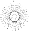
- Example 1 of the permanent-magnet-type rotary electric machine of this invention It is sectional drawing which shows Example 1 of the permanent-magnet-type rotary electric machine of this invention. It is sectional drawing which shows the shape of the rotor of the permanent magnet type rotary electric machine shown in FIG. It is principal part sectional drawing which shows the stator core shape of the stator of the permanent magnet type rotary electric machine shown in FIG. It is sectional drawing which shows the reference example of a permanent magnet type rotary electric machine. It is a figure which shows Example 2 of this invention, and is a longitudinal cross-sectional view of the compressor using the permanent magnet type rotary electric machine. It is a figure which shows Example 3 of this invention, and is sectional drawing which shows the shape of the rotor of a permanent magnet type rotary electric machine, and is a figure equivalent to FIG.
- Example 1 of the permanent magnet type rotating electrical machine of the present invention will be described with reference to FIGS. 1 is a sectional view showing a first embodiment of a permanent magnet type rotating electrical machine according to the present invention
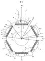
- FIG. 2 is a sectional view showing a shape of a rotor of the permanent magnet type rotating electrical machine shown in FIG. 1
- FIG. 3 is a permanent view shown in FIG.
- FIG. 4 is a cross-sectional view showing a main part of a stator core of a stator of a magnet-type rotating electrical machine
- FIG. 1 is a sectional view showing a first embodiment of a permanent magnet type rotating electrical machine according to the present invention
- FIG. 2 is a sectional view showing a shape of a rotor of the permanent magnet type rotating electrical machine shown in FIG. 1
- FIG. 3 is a permanent view shown in FIG.
- FIG. 4 is a cross-sectional view showing a main part of a stator core of a stator of a magnet-type rotating electrical machine
- the present invention is applied to a permanent magnet type rotating electrical machine constituted by a 6-pole rotor and a 9-slot stator (6-pole 9-slot).
- the ratio of the number of rotor poles to the number of slots in the stator is 2: 3, but the ratio between the number of other poles and the number of slots and the number of poles of the other rotor and the number of slots in the stator is used.
- the present invention can be similarly applied to a thing, and almost the same effect can be obtained.
- the number of poles of the rotor may be 4 poles or 8 poles.
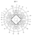
- the permanent magnet type rotating electric machine shown in FIG. 4 includes a 4-pole rotor and a 6-slot stator.
- the permanent magnet type rotating electrical machine in the present embodiment is a so-called embedded magnet type rotating electrical machine in which a permanent magnet is embedded in a rotor core.
- axial direction indicates the rotational axis direction of the rotor
- radial direction indicates the radial direction of the rotor
- circumferential direction indicates the circumferential direction of the rotor.
- the sectional view of the permanent magnet type rotating electrical machine of this embodiment shown in FIG. 1 shows a section in a direction perpendicular to the rotation axis (the same applies to FIGS. 2 to 4 and 6 described later).
- the first embodiment operates as a permanent magnet type synchronous motor.
- a permanent magnet type rotating electrical machine 1 is arranged to rotate with a stator 2 and a predetermined gap (gap) inside the stator 2 and rotating with a shaft (not shown). It is composed of a child 3.
- the stator 2 includes a stator core 6 including an annular core back 5 and nine teeth 4 that protrude radially inward from the core back 5 and are arranged at substantially equal intervals along the circumferential direction. , And a concentrated winding armature winding 8 or the like wound so as to surround the teeth 4 in a slot 7 between the teeth 4 adjacent to each other in the circumferential direction. It is fixed to the closed container of the machine by shrink fitting or press fitting.
- the armature winding 8 is wound around the axial center of the tooth 4 radially arranged in the radial direction, and in the circumferential direction, a U-phase winding 8a, a V-phase winding 8b, W-phase windings 8c are arranged with a gap therebetween.
- the stator 2 is configured by laminating the stator cores 6 (magnetic steel plates) in the axial direction, and nine slots (9 slots) are formed between the adjacent teeth 4. Yes.
- the rotor 3 is composed of a rotor core 12 and six permanent magnets 14 embedded in the outer peripheral portion of the rotor core 12 and arranged at substantially equal intervals in the circumferential direction. Is a 6-pole rotor.
- a shaft hole 15 is formed in the center of rotation of the rotor 3, and a cylindrical shaft (not shown) is integrally fixed to the shaft hole 15, and the rotor 3 is an inner part of the stator 2. It is rotatably arranged on the peripheral surface side via a gap.
- the rotor 3 has 6 poles and the stator 2 has 9 slots (6 poles 9 slots).
- the angle is 120 degrees (mechanical angle is 40 degrees).
- the permanent magnet type rotating electrical machine 1 of the present embodiment when a three-phase alternating current is passed through the armature winding 8 composed of the three-phase windings 8a to 8c, a rotating magnetic field is generated. Due to this rotating magnetic field, the rotor 3 is rotated by electromagnetic force acting on the permanent magnet 14 and the rotor core 12 embedded in the rotor 3.
- stator core 6 and the rotor core 12 are: It is preferable to form a laminated body in which a plurality of thin plates made of magnetic steel plates such as silicon steel plates are stacked.
- FIG. 2 is a sectional view of the rotor of the permanent magnet type rotating electric machine according to the first embodiment of the present invention.
- the rotor 3 has the rotor core 12 in which a shaft hole 15 is formed at the center of rotation.
- a plurality of rectangular permanent magnet insertion holes 13 having an elongated cross section (six poles in the first embodiment) are formed.
- Each of the plurality of permanent magnet insertion holes 13 is inserted with a flat, single-letter permanent magnet 14 made of a magnet material, for example, rare earth neodymium.
- the direction of the magnetic flux generated by the magnetic pole of the permanent magnet 14, that is, the virtual axis connecting the longitudinal center (cross section center) of the permanent magnet 14 and the rotation center is the d axis (flux axis).
- the axis (electric axis between permanent magnets) that is electrically orthogonal to the d-axis, that is, the electrical angle, is defined as the q-axis.
- the rotor 3 is provided with one permanent magnet 14 per magnetic pole.
- the cross-sectional shape of the permanent magnet 14 is an elongated rectangular shape similar to the permanent magnet insertion hole 13, and the longitudinal direction of the permanent magnet 14 extends in a direction perpendicular to the d axis.
- the rotor core 12 of the rotor 3 is provided with a rotor recess 11 that is recessed inward on the q axis between the poles of adjacent permanent magnets 14.
- the rotor recess 11 suppresses the q-axis magnetic flux as will be described later.
- the rotor 3 that is, the rotor core 12, is located on the outer peripheral side of the rotor recess 11, and has an arcuate outermost periphery in which the gap length (gap) between the stator 2 and the teeth 4 is the shortest g 1.
- the magnetic pole surface of the rotor core 12 has a cut portion 12b connected to the end of the arcuate portion 12a, and the arcuate portion 12a passes through the cut portion 12b and the rotor concave portion. 11 is connected.
- a gap length g2 between the cut portion 12b and the teeth 4 of the stator 2 is configured to be wider than a gap length g1 between the arc-shaped portion 12a and the teeth 4 of the stator 2.
- the cut portion 12b is formed in a straight line shape, but is not necessarily limited to a straight line shape, and may be a curved surface shape.
- the angle ⁇ p3 of the arc-shaped portion 12a around the rotation center O of the rotor 3, that is, the angle ⁇ p3 at which two straight lines connecting both ends of the arc-shaped portion 12a and the rotation center O intersect is The angle is 90 ° to 120 °.
- the rotor concave portion 11 smoothly smoothes two linear portions 11b and 11c formed substantially parallel to the radial thickness direction of the permanent magnet 14 and the rotor inner peripheral side end portions of the two linear portions 11b and 11c.
- the curved portion 11a is connected between the ends facing the q-axis on the inner peripheral side magnetic pole surface of two adjacent permanent magnets located on both sides of the q-axis, that is, the latest It is located on the rotor inner peripheral side from the virtual straight line 9 connecting the contact portions.
- the starting position of the curved portion 11a is substantially located at the portion of the virtual straight line 9, but may be located at the rotor inner peripheral side of the virtual straight line 9.
- the start position of the curved portion 11a may be configured to be positioned on the outer peripheral side of the virtual straight line 9. good.
- the bottom of the rotor recess 11 in the radial direction is configured to be deeper than the inner peripheral side magnetic pole surface of the permanent magnet 14.
- the interval between the two straight portions 11b and 11c is configured to increase from the rotor inner peripheral side toward the rotor outer peripheral side.
- the cross-sectional area of the rotor recess 11 is configured to be larger than the cross-sectional area of the cut portion 12b.
- the angle between the end portions of the outer peripheral side magnetic pole surface of the permanent magnet 14 constituting one magnetic pole of the rotor 3 is ⁇ p1
- the two linear portions of the rotor recess 11 When the angle between the end portions of the outer peripheral side of the rotors 11b and 11c is ⁇ p2, in this embodiment, the angles ⁇ p1 and ⁇ p2 are 0.18 ⁇ ⁇ p2 / ⁇ p1 ⁇ 0.5 It is set to satisfy the relationship.
- the pitch of the slots 7 in the stator 2 having concentrated windings is 120 ° in electrical angle.
- the rotor 3 has an outer peripheral side of the permanent magnet insertion hole 13 (or the permanent magnet 14) (the arc-shaped portion 12a in the rotor core 12 and the outer peripheral side magnetic pole surface of the permanent magnet 14).
- the plurality of slits 10a to 10d are provided symmetrically so as to sandwich the d-axis on both the left and right sides separated by a predetermined distance from the d-axis. Further, no slit is provided on the d-axis and in the vicinity of the d-axis so that the magnetic flux easily passes through the vicinity of the d-axis.
- the slits 10a and 10b are arranged symmetrically with respect to the d-axis, and the slits 10c and 10d are arranged symmetrically with respect to the d-axis between the slits 10a and 10b.
- the distance between the slits 10c and 10d arranged closest to the d-axis is set to the minimum width of the tooth 4 in general.
- the distance between the end portions of 10d is set to the minimum width of the teeth 4 in general.
- the slits 10 a to 10 d are arranged so as to be inclined so that the magnetic flux of the permanent magnet 14 is collected on the teeth 4. That is, the direction in which the slits 10a to 10d go to the outer peripheral side is inclined inward from a direction parallel to the d-axis so as to make an acute angle with the d-axis. Since the induced electromotive force waveform can be made sine wave by such slits 10a to 10d, the armature current can be made sine wave accordingly, and the harmonic magnetic flux generated by the interaction between the induced electromotive force and the armature current is reduced. can do. That is, the slits 10a to 10d suppress the armature reaction and reduce the harmonic component of the magnetic flux in the rotating electric machine.
- the concentrated winding armature winding 8 is a winding arranged at an electrical angle of 120 degrees, so that harmonic components such as the fifth and seventh orders of the in-machine magnetic flux are large, causing vibration and noise.
- the pulsating torque and the radial electromagnetic excitation force are also increased.
- FIG. 4 shows a reference example similar to Patent Document 1 described above.
- the tip portion (tooth tip portion) 16 of the teeth 4 in the stator 2 has a central portion concentric with the rotor core 12, and both ends of the teeth tip portion 16 are linear. That is, it is kept away from the rotor core 12.
- the induced electromotive force waveform can be converted into a sine wave and the armature current can be converted into a sine wave, so that the harmonic magnetic flux generated by the interaction between the induced electromotive force and the armature current can be reduced. Torque and radial electromagnetic excitation force can be reduced.
- the shape of the stator 2 is configured as shown in FIG. That is, in this embodiment, as shown in FIG. 3, a stator concave portion 17 is provided on the outer peripheral side of the teeth 4 of the stator core 6.
- the stator 2 is fixed to a compressor frame (sealed container) or the like by shrink fitting or press fitting (see FIG. 5 to be described later). In this case, the contact portion between the frame and the stator 2 is fixed.
- An arc portion 5a on the outer periphery of the core back 5 of the core 6 is formed, and the stator 2 is fixed to the frame by the arc portion 5a.
- the arc portion 5 a fixed to the frame and the stator recess 17 formed on the outer peripheral side of the teeth 4 are provided. Yes.
- the stator recess 17 includes three straight portions (17a, 17b, 17c) along (parallel to) the width direction of the teeth 4 and two straight portions (17d) respectively connecting the end portions of the three straight portions. , 17e). That is, the stator concave portion 17 is connected to one of the circular arc portions 5a and parallel to the width direction of the teeth 4, and the circular arc portion is provided on the other side across the teeth. A second linear portion 17b connected to the circular arc portion and parallel to the width direction of the teeth, and a second linear portion 17b provided between the first and second linear portions and radially inward and parallel to the width direction of the teeth.
- stator recess 17 is not in contact with the frame.
- the distance between the left and right ends of the tooth tip 16 inside the slot 7 is L1
- the width of the tooth 4 is L2
- the arc portion 5a and the stator recess 17 provided on both sides of the stator recess 17 are provided.
- a straight line distance connecting the intersecting points (a distance of a portion not in contact with the frame on the back side of the teeth 4) is defined as L3.
- the distance L3 will be described in more detail.
- L2 ⁇ L1 ⁇ L3 It is configured to satisfy the relationship.
- the depth L4 of the stator recess 17 is configured to be shorter than the length of the teeth 4 and the thickness of the core back 5 so that the flow of effective magnetic flux in the rotating electrical machine is not impaired as much as possible.
- the first embodiment is a permanent magnet type rotating electric machine that combines the structure of the rotor 3 described in FIG. 2 and the structure of the stator 2 described in FIG. Since the harmonic component of the magnetic flux in the rotating electrical machine due to the influence can be sufficiently reduced, the generation of the pulsating torque and the radial electromagnetic excitation force can be suppressed to achieve a small size, high efficiency, and low noise. Further, it is possible to suppress pulsation torque and radial electromagnetic excitation force generated in the rotating electrical machine from being transmitted to the frame.
- this permanent magnet type rotating electrical machine 1 is used in a compressor constituting a refrigeration cycle, it is small and highly efficient. A low noise compressor can be obtained.
- the harmonic component of the magnetic flux can be reduced without reducing the slot cross-sectional area of the stator, a small-sized, high-efficiency, low-noise permanent magnet type rotating electrical machine and The effect which can obtain the used compressor is acquired.
- FIG. 5 is a longitudinal sectional view of a compressor using a permanent magnet type rotating electrical machine, showing the second embodiment.
- a compressor 20 shown in FIG. 5 includes a compression mechanism unit 21 that reduces the volume of a gas that is a working fluid such as a refrigerant, and an electric motor unit 22 that drives the compression mechanism unit 21, and the electric motor unit 22 is the above-described one.
- the permanent magnet type rotating electrical machine 1 of the first embodiment is mounted.
- the compressor 20 in the second embodiment is used in a refrigeration cycle apparatus such as an air conditioner, and the compression mechanism portion 21 and the electric motor portion 22 are accommodated in a cylindrical sealed container (frame) 23. ing. Further, R32 refrigerant is sealed as a working fluid in the sealed container 23.
- the compression mechanism portion 21 is constituted by a scroll compression mechanism including a fixed scroll 24 and a turning scroll 25, and the fixed scroll 24 is attached to a frame 26 fixed to the inner surface of the hermetic container 23 with a bolt or the like. Fastened by fastening means.
- the fixed scroll 24 includes an end plate 24a, a spiral fixed scroll wrap 24b formed so as to stand upright on the end plate 24a, a discharge port 24c formed in a substantially central portion of the end plate 24a, and the like.
- the orbiting scroll 25 includes an end plate 25a, a spiral orbiting scroll wrap 25b formed so as to stand upright on the end plate 25a, a boss portion 25c formed at the center of the back surface of the end plate 25a, and the like. Yes.
- the orbiting scroll 25 is meshed with the fixed scroll 24 and the electric motor unit (permanent magnet type rotating electrical machine) 22 rotates, whereby the orbiting scroll 25 is orbitally moved via the crankshaft 27 to perform a compression operation. .
- crankshaft 27 is inserted into a shaft hole 15 (see FIGS. 1 and 2) formed in the rotor 3 of the electric motor unit 22 and is configured integrally with the rotor 3.
- the crankshaft A crank portion (eccentric pin portion) 27a is formed at the upper end portion of 27.
- the crank portion 27 a of the crankshaft 27 is inserted into and engaged with the boss portion 25 c of the orbiting scroll 25.
- the crankshaft 27 is rotatably supported by a slide bearing (main bearing) 28 provided on the frame 26 and a ball bearing 30 provided on a lower frame 29 in the lower part of the sealed container 23.
- the crankshaft 27 also rotates, causing the orbiting scroll 25 to perform an orbiting motion via the crank portion 27a.
- the orbiting scroll 25 starts the orbiting motion, the refrigerant gas of the refrigeration cycle is sucked into the suction chamber formed on the outer peripheral side of the fixed scroll 24 from the suction pipe 31 and is formed by the fixed scroll 24 and the orbiting scroll 25 from here. After being confined in the compression chamber 32, it is compressed along with the orbiting motion of the orbiting scroll 25, moves to the center side, and is discharged from the discharge port 24 c to the discharge chamber above the sealed container 23.
- the compression chamber located on the outermost diameter side among the compression chambers 32 formed by the fixed scroll 24 and the orbiting scroll 25 moves toward the centers of the scroll members 24 and 25 along with the orbiting motion,
- the volume gradually decreases.
- the compression chamber 32 communicates with the discharge port 24c, and the compressed gas is discharged from the compression chamber 32 to the discharge chamber through the discharge port 24c.
- the discharged compressed refrigerant gas flows from the discharge chamber through the gas passage 33 provided on the outer peripheral side of the fixed scroll 24 and the frame 26 to the electric motor chamber side below the frame 26 and in the refrigerant gas.
- the oil is supplied to the refrigeration cycle from a discharge pipe 34 provided on the side wall of the sealed container 23.
- the separated oil is stored in an oil reservoir 35 formed in the lower part of the sealed container 23.
- the oil stored in the oil reservoir 35 passes through an oil hole 36 formed in the crankshaft 27 in the axial direction, and the centrifugal force due to the rotation of the crankshaft 27 and the difference between the discharge pressure and the low pressure side.
- the sliding bearing 28, the ball bearing 30, and the sliding portion of the compression mechanism 21 are supplied by pressure.
- 8 is an armature winding of the stator 2
- 37 is a balance weight
- 38 is a power supply terminal.
- the electric motor unit 22 composed of the permanent magnet type rotating electrical machine 1 is controlled by a separate inverter (not shown) and is rotated at a rotation speed suitable for the compression operation.
- Table 1 shows a conventional general permanent magnet having various rotor shapes and stator shapes only in the permanent magnet type rotating electric machine, with the same basic configuration as the compressor 20 of the second embodiment described above. It is the measurement result which conducted the auditory test of the noise by the compressor incorporating the rotary electric machine and the compressor carrying the rotary electric machine of the reference example shown in FIG.
- the frequency bands of annoying noises are roughly divided into three ranges: low, middle and high.
- the low frequency range is less than 1 kHz
- the middle frequency range is 1 kHz or more and less than 4 kHz
- the high frequency range is 4 kHz or more and 10 kHz or less.
- the noise component in the middle range which is particularly problematic in hearing, appears more prominently in a compressor equipped with a conventional general permanent magnet type rotating electrical machine (hereinafter also referred to as a conventional compressor).
- the compressor hereinafter also referred to as the compressor of the reference example
- the rotating electrical machine of the reference example shown in FIG. 4 has a reduction effect on the low-frequency and high-frequency noise components as compared with the conventional compressor.
- the audibility with respect to the mid-range noise component it was not sufficiently reduced.
- the lower order harmonic components such as the fifth order and the seventh order
- the relatively higher order such as the 25th order and 27th order components. It has been observed that the harmonic components of are greatly reduced. However, it has been found that the relatively middle harmonic components such as the 11th and 13th components and the 15th and 17th components are not reduced as the harmonic components of the magnetic flux in the rotating electrical machine.
- the lower-order and higher-order harmonic components of the magnetic flux in the rotating electric machine can be reduced and compared with the compressor according to the reference example. It was also found that the harmonic components in the target midrange could be significantly reduced compared to the compressor of the reference example. This is because, in the case of the compressor of the second embodiment, the harmonic component of the magnetic flux in the rotating electrical machine can be sufficiently reduced, and the pulsating torque and the radial electromagnetic excitation force in the rotating electrical machine are reduced by the compressor 20. This is because it is possible to suppress the transmission to the hermetic container (frame) 23.
- the overall noise value was 67.4 dB, whereas in the compressor of the second embodiment, the noise value was reduced to 64.3 dB. Has been.
- the compressor of the second embodiment it is possible to greatly reduce the noise component in the middle range, which is a problem particularly in hearing, and to reduce the overall noise value.
- the permanent magnet type rotating electrical machine 1 of the first embodiment described above is used for the compression chamber 20, a compact, high-efficiency, low-noise compressor 20 can be obtained. It can. That is, since the permanent magnet type rotating electric machine 1 has the rotor 3 having the structure described with reference to FIG. 2, the torque of the permanent magnet type rotating electric machine 1 can be made larger than that of the conventional one, particularly in the high speed range. Moreover, since the power factor fall by the influence of an armature reaction can also be suppressed, the torque fall in a high speed region is suppressed. For this reason, it becomes possible to achieve high efficiency and downsizing of the permanent magnet type rotating electrical machine.
- the efficiency of the compressor can be improved and energy can be saved.
- the operating range can be expanded, such as enabling high-speed operation of the compressor.
- the R410A refrigerant is sealed in the sealed container 23, and the ambient temperature of the permanent magnet type rotating electric machine is often 80 ° C. or higher.
- the ambient temperature since the R32 refrigerant having a smaller global warming potential is employed, the ambient temperature further increases.
- the permanent magnet 14, particularly a neodymium magnet has a residual magnetic flux density that decreases at a high temperature, and an armature current increases to ensure the same output, but the high-efficiency permanent magnet type rotating electrical machine 1 of the first embodiment is mounted. A reduction in efficiency can be suppressed by using the compressor.
- R32 is adopted as the refrigerant.
- refrigerants such as R32 and He have a larger leakage from the gap in the compressor than refrigerants such as R22, R407C, and R410A, and are particularly slow.
- the ratio of leakage to the amount of circulation increases, which reduces efficiency.
- the compression mechanism is downsized and the rotational speed is increased to obtain the same circulation, leakage loss can be reduced.
- the compressor equipped with the permanent magnet type rotating electrical machine 1 of the first embodiment it is possible to increase the maximum torque and the maximum rotation speed, and it is possible to reduce the loss in a high speed region.
- the compressor according to the second embodiment is particularly effective when a refrigerant that easily leaks, such as R32 or He, is used as the refrigerant, and the efficiency can be improved.
- stator concave portion 17 having a large area is provided on the outer periphery of the stator 2 in the permanent magnet type rotating electrical machine 1, an airtight container (frame) 23 is provided.
- Lubricating oil that has reached the upper surface of the stator 2 along the inner peripheral surface easily passes through the stator recess 17. As a result, it is possible to reduce the oil rise that the amount of lubricating oil in the compressor is insufficient during high-speed operation.
- R32 is used as a refrigerant, but the present invention is not limited to the type of refrigerant.
- the compressor is a scroll compressor.
- the present invention can be similarly applied to a compressor having another compression mechanism such as a rotary compressor. is there.
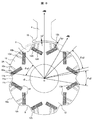
- FIG. 6 is a diagram illustrating the third embodiment, which is a cross-sectional view illustrating the shape of the rotor of the permanent magnet type rotating electrical machine, and corresponds to FIG. 2 described above.
- FIG. 6 the same parts as those in FIG. 2 are denoted by the same reference numerals, description thereof is omitted, and different parts are described.
- the third embodiment is different from the rotor 3 shown in FIG. 2 of the first embodiment, and includes two permanent magnets 14A per magnetic pole of the rotor 3A.
- the two permanent magnets 14 ⁇ / b> A are arranged in a convex V shape with respect to the shaft hole 15. That is, the cross sections of the two permanent magnets 14A have the same shape as that of the first embodiment, but are arranged in a convex V shape toward the rotation center O of the rotor 3 with the d axis as the axis of symmetry. As a result, high torque is achieved.
- the other configuration of the rotor 3A in the third embodiment is the same as that of the rotor 3 of the first embodiment.
- the rotor recess 11 is provided, and the values of the angles ⁇ p1, ⁇ p2, ⁇ p3, etc. in the rotor 3A are similarly configured.
- the harmonics of the magnetic flux in the rotating electric machine due to the influence of the armature reaction. Since the components can be sufficiently reduced, the generation of pulsation torque and radial electromagnetic excitation force can be suppressed to achieve a small size, high efficiency, and low noise. Further, it is possible to suppress pulsation torque and radial electromagnetic excitation force generated in the rotating electrical machine from being transmitted to the frame. Furthermore, also in the third embodiment, as in the first embodiment, it is possible to suppress the torque reduction in the high speed range, and from this point, it becomes possible to increase the efficiency and miniaturization of the permanent magnet type rotating electric machine. 1 can be obtained.
- SYMBOLS 1 Permanent magnet type rotary electric machine (drive motor), 2 ... Stator, 3, 3A ... Rotor, 4 ... Teeth, 5 ... Core back, 5a ... Arc part, 5b ... Stator recessed part, 6 ... Stator core 7 ... slot, 8 armature winding, 8a ... U phase winding, 8b ... V phase winding, 8c ... W phase winding, 9 ... virtual straight line, 10a, 10b, 10c, 10d ... slit, 11 ... rotation Child concave part, 11a ... curve part, 11b, 11c ... linear part, 12 ... rotor core, 12a ... arc-shaped part, 12b ...
- Crank part, 28 Sliding bearing (main bearing), 29 ... Lower frame, 30 ... Ball bearing, 31 ... Suction pipe, 32 ... Compression chamber, 33 ... Gas passage, 34 ... Discharge pipe, 35 ... oil retaining part, 36 ... oil hole, 37 ... balance weight, 38 ... power terminal.
Landscapes
- Engineering & Computer Science (AREA)
- Power Engineering (AREA)
- Iron Core Of Rotating Electric Machines (AREA)
- Permanent Field Magnets Of Synchronous Machinery (AREA)
- Compressor (AREA)
- Permanent Magnet Type Synchronous Machine (AREA)
Abstract
小形、高効率で低騒音な永久磁石式回転電機を得る。 永久磁石式回転電機は、複数のティースとスロットを有する固定子鉄心と、電機子巻線を有する固定子と、回転子鉄心と、これに埋設された複数の永久磁石とを有する回転子を備える。固定子は、フレームに固定される円弧部と、外周側に形成された固定子凹部を備え、該固定子凹部は、円弧部と接続されティースの幅方向に平行な第1、第2の直線部と、径方向内側に設けられティースの幅方向に平行な第3の直線部と、この第3の直線部と第1、第2の直線部を接続する第4、第5の直線部を有して略台形形状に形成され、ティース先端部のスロット内側の両端の距離をL1、ティースの幅をL2、固定子凹部を挟んで両側に設けられた前記円弧部と前記固定子凹部とが交わる点どうしを結ぶ直線距離をL3としたとき、「L2<L1<L3」の関係に構成されている。
Description
本発明は、界磁用の永久磁石を回転子に備えている永久磁石式回転電機に係り、特に、エアコン、冷蔵庫、冷凍庫、或いは食品ショーケースなどにおける圧縮機に使用するのに好適な永久磁石式回転電機及びそれを用いる圧縮機に関する。
従来、この種の永久磁石式回転電機においては、電機子巻線となる固定子巻線に集中巻が採用されると共に、界磁には希土類のネオジムの永久磁石が採用され、小形・高効率化が図られている。しかし、小形・高効率化による出力密度の増加に伴い、鉄心の非線形磁気特性(ヒステリシス)の影響が顕著になり、集中巻の採用と相俟って、空間高調波磁束が増大している。
これに対し、実開平3-106869号公報(特許文献1)に記載の従来技術のものでは、固定子鉄心におけるティース先端部(回転子鉄心との対向面)の形状を、中央部は回転子鉄心の外周面と同心円に形成し、円周方向両端部は直線状(平坦面)に形成することで回転子鉄心外周面から遠ざけるようにしたものが記載されている。これにより、ギャップ面における高調波磁束を低減させている。
固定子巻線に集中巻が採用され且つ界磁に高磁束密度の永久磁石が採用されることにより、永久磁石式回転電機の効率は飛躍的に向上した。その反面、固定子巻線を分布巻としたものに対し集中巻としたものでは、原理的に高調波磁束が増加することに加え、その高調波磁束を高磁束密度の永久磁石が助長する結果となる。つまり、小形・高効率化による出力密度の増加に伴い鉄心の非線形磁気特性が増加し、更に高磁束密度の永久磁石は磁力が大きくなるため、永久磁石式回転電機そのものの振動や騒音も増加し易く、特に、圧縮機に組み込んだ場合に最も耳障りとされている中域の周波数帯が顕在化する課題がある。
上記特許文献1のものでは、固定子鉄心におけるティース先端部の形状を、中央部は回転子鉄心と同心円とし、円周方向両端部は直線状にして回転子鉄心外周面から遠ざけることで、ギャップ面における高調波磁束を低減させている。これにより、誘導起電力波形を正弦波化して電機子電流を正弦波化でき、誘導起電力と電機子電流との相互作用によって生じる高調波磁束を低減するようにしている。この結果、永久磁石式回転電機に発生する脈動トルクや径方向電磁加振力を低減できるので、振動や騒音を低減できる。
しかし、上記特許文献1のものでは、比較的低域の周波数帯と比較的高域の周波数帯に生じている騒音は低減できるものの、最も耳障りとされている中域の周波数帯の騒音に対しては十分に低減できていない。
この理由は、特許文献1の場合、ティース先端部の両端部を回転子鉄心外周面から遠ざけるほど、固定子のスロット断面積が減少し、スロットに挿入する電機子巻線が少なくなってしまうため、永久磁石式回転電機の効率などの性能を低下させることなく、電動機内の磁束の高調波成分を低減するのには限界があったためである。
また、圧縮機の低騒音化のためには、電動機自体から発生する振動を小さくするか、電動機の振動が圧縮機のフレーム(例えば密閉容器)に伝わらないようにする必要がある。電動機の振動を小さくするためには、上述したように、永久磁石式回転電機(電動機)内に発生する磁束の高調波成分を低減して、脈動トルクや径方向電磁加振力を小さくすること等が有効である。
一方、電動機の振動が圧縮機のフレームに伝わらないようにするためには、電動機の振動を減衰させる機能を持たせた電動機構造や固定方法が有効である。
従って、圧縮機の高効率・低騒音化のためには、電動機内に発生する磁束の高調波成分を十分に低減して脈動トルク及び径方向電磁加振力を小さくし、且つ圧縮機のフレームに電動機の振動が伝わり難い構造にすることが重要である。
本発明の目的は、小形、高効率で低騒音な永久磁石式回転電機及びそれを用いた圧縮機を得ることにある。
上記目的を達成するため、本発明は、円環形状のコアバックと、該コアバックから径方向内側へ向けて突出し周方向に配列された複数のティースと、該ティース間に形成された複数のスロットを有する固定子鉄心と、前記スロット内に配設され前記ティースに巻装された電機子巻線とを有し、フレームに固定された固定子と、回転子鉄心と、該回転子鉄心に埋設され周方向に複数配設された永久磁石とを有し、前記固定子と空隙を介して回転自在に配置されている回転子と、を備える永久磁石式回転電機において、前記固定子は、前記コアバックにおける前記スロットの外周側に形成され前記フレームに固定される円弧部と、前記コアバックにおける前記ティースの外周側に形成された固定子凹部とを備え、前記固定子凹部は、前記円弧部の1つと接続され前記ティースの幅方向に平行な第1の直線部と、前記円弧部とは前記ティースを挟んで他方側に設けられた円弧部と接続され前記ティースの幅方向に平行な第2の直線部と、前記第1、第2の直線部の間で且つ径方向内側に設けられ前記ティースの幅方向に平行な第3の直線部と、この第3の直線部の一端と前記第1の直線部を接続する第4の直線部と、前記第3の直線部の他端と前記第2の直線部を接続する第5の直線部とを有して略台形形状に形成され、前記ティースにおけるティース先端部のスロット内側の両端の距離をL1、前記ティースの幅をL2、前記固定子凹部を挟んで両側に設けられた前記円弧部と前記固定子凹部とが交わる点どうしを結ぶ直線距離をL3とした場合、
L2<L1<L3
の関係になるように構成したことを特徴とする。
L2<L1<L3
の関係になるように構成したことを特徴とする。
本発明の他の特徴は、作動流体である気体の容積を縮小する圧縮機構部と、この圧縮機構部を駆動する永久磁石式回転電機と、を備える圧縮機において、前記永久磁石式回転電機は、上述した永久磁石式回転電機を搭載していることを特徴とする圧縮機。
本発明によれば、小形、高効率で低騒音な永久磁石式回転電機及びそれを用いた圧縮機を得ることができる効果がある。
以下、本発明の永久磁石式回転電機及びそれを用いた圧縮機の具体的実施例を、図面を用いて説明する。各図において、同一符号を付した部分は同一或いは相当する部分を示している。
本発明の永久磁石式回転電機の実施例1を、図1~図4を用いて説明する。図1は本発明の永久磁石式回転電機の実施例1を示す断面図、図2は図1に示す永久磁石式回転電機の回転子の形状を示す断面図、図3は図1に示す永久磁石式回転電機の固定子の固定子鉄心形状を示す要部断面図、図4は永久磁石式回転電機の参考例を示す断面図である。
本実施例1の説明では、6極の回転子と9スロットの固定子(6極9スロット)から構成された永久磁石式回転電機に本発明を適用した場合について説明する。なお、回転子の極数と固定子のスロット数との比は2:3としているが、他の極数やスロット数、他の回転子の極数と固定子のスロット数との比としたものに対しても同様に適用でき、ほぼ同様の効果を得ることができる。例えば、回転子の極数は、4極や8極などにしても良い。なお、図4に示す永久磁石式回転電機は、4極の回転子と6スロットの固定子から構成されている。また、本実施例における永久磁石式回転電機は、永久磁石が回転子鉄心に埋設される、いわゆる埋込磁石型の回転電機である。
以下の説明において、「軸方向」とは回転子の回転軸方向を示し、「径方向」とは回転子の径方向を示し、「周方向」とは回転子の周方向を示す。
図1に示す本実施例の永久磁石式回転電機の断面図は、回転軸に垂直な方向の断面を示している(後述する図2~4、6も同様)。なお、本実施例1は、永久磁石式同期電動機として動作する。
図1に示す本実施例の永久磁石式回転電機の断面図は、回転軸に垂直な方向の断面を示している(後述する図2~4、6も同様)。なお、本実施例1は、永久磁石式同期電動機として動作する。
図1に示すように、永久磁石式回転電機1は、固定子2と、該固定子2の内側に所定のギャップ(空隙)を介して配置され、且つシャフト(図示せず)と共に回転する回転子3とから構成される。
前記固定子2は、円環形状のコアバック5と、該コアバック5から径方向内側へ向けて突出し周方向に沿って略等間隔に配列された9つのティース4とからなる固定子鉄心6、及び周方向に隣接する前記ティース4間のスロット7内において前記ティース4を取り囲むように巻装される集中巻の電機子巻線8等により構成され、この固定子2はフレーム(例えば、圧縮機の密閉容器など)に焼き嵌め或いは圧入等により固定されている。
前記固定子2は、円環形状のコアバック5と、該コアバック5から径方向内側へ向けて突出し周方向に沿って略等間隔に配列された9つのティース4とからなる固定子鉄心6、及び周方向に隣接する前記ティース4間のスロット7内において前記ティース4を取り囲むように巻装される集中巻の電機子巻線8等により構成され、この固定子2はフレーム(例えば、圧縮機の密閉容器など)に焼き嵌め或いは圧入等により固定されている。
即ち、電機子巻線8は、径方向に放射状に配される前記ティース4の軸心周りに巻装され、周方向に、三相巻線のU相巻線8a、V相巻線8b、W相巻線8cが相互に空隙を介して配される。
なお、前記固定子2は、前記固定子鉄心6(電磁鋼板)が軸方向に積層されて構成されており、また前記スロット7は隣り合う前記ティース4間に9つ(9スロット)形成されている。
なお、前記固定子2は、前記固定子鉄心6(電磁鋼板)が軸方向に積層されて構成されており、また前記スロット7は隣り合う前記ティース4間に9つ(9スロット)形成されている。
前記回転子3は、回転子鉄心12と、この回転子鉄心12の外周部側に埋設され周方向に略等間隔に配設された6個の永久磁石14等により構成されており、極数が6極の回転子となっている。この回転子3の回転中心部にはシャフト孔15が形成されており、このシャフト孔15には円柱状のシャフト(図示せず)が一体に固定され、回転子3は前記固定子2の内周面側に空隙を介して回転自在に配置されている。
本実施例の永久磁石式回転電機1は、前記回転子3の極数が6極、前記固定子2のスロット数が9スロット(6極9スロット)であるから、スロット7のピッチθsは電気角で120度(機械角で40度)である。
本実施例の永久磁石式回転電機1においては、三相の前記巻線8a~8cからなる電機子巻線8に三相交流電流を流すと、回転磁界が発生する。この回転磁界によって、前記回転子3に埋設されている前記永久磁石14及び前記回転子鉄心12に働く電磁力により、回転子3が回転する。
なお、永久磁石式回転電機1が動作する時に固定子鉄心6及び回転子鉄心12に発生する渦電流損などの鉄損を低減するために、前記固定子鉄心6及び前記回転子鉄心12は、珪素鋼板などの磁性鋼板からなる薄板を複数積層した積層体によって構成することが好ましい。
図2は本発明の実施例1による永久磁石式回転電機の回転子の断面図である。
図2において、回転子3は、その回転中心部にシャフト孔15が形成された前記回転子鉄心12を有する。この回転子鉄心12内の外周側表面の近傍には、断面が細長い長方形状の永久磁石挿入孔13が複数(本実施例1では極数分である6個)形成されている。これらの複数の永久磁石挿入孔13には、それぞれ、磁石材料、例えば希土類のネオジムからなる、平板状で一文字状の前記永久磁石14が挿入されている。
図2において、回転子3は、その回転中心部にシャフト孔15が形成された前記回転子鉄心12を有する。この回転子鉄心12内の外周側表面の近傍には、断面が細長い長方形状の永久磁石挿入孔13が複数(本実施例1では極数分である6個)形成されている。これらの複数の永久磁石挿入孔13には、それぞれ、磁石材料、例えば希土類のネオジムからなる、平板状で一文字状の前記永久磁石14が挿入されている。
ここで、図2の回転子断面において、前記永久磁石14の磁極がつくる磁束の方向、つまり永久磁石14の長手方向中心(断面中央)と回転中心とを結ぶ仮想軸をd軸(磁束軸)と定義し、d軸と電気的に、即ち電気角で直交する軸(永久磁石間の軸)をq軸と定義する。
図2に示すように、本実施例では、前記回転子3には、一磁極当たり一枚の永久磁石14が設けられている。前記永久磁石14の断面形状は、前記永久磁石挿入孔13と同様に細長い長方形状であり、前記永久磁石14の長手方向はd軸に対して幾何的に直角方向に伸びている。
回転子3の回転子鉄心12には、隣接する永久磁石14の極間のq軸上において、内周側に凹む回転子凹部11が設けられている。この回転子凹部11は、後述するようにq軸磁束を抑制する。
また、回転子3、即ち回転子鉄心12は、前記回転子凹部11よりも外周側に位置し、固定子2のティース4とのギャップ長(空隙)が最短のg1となる円弧状の最外周部、即ち前記回転子鉄心12における磁極面を構成する円弧状部12aを有する。
本実施例では、前記回転子鉄心12における磁極面は、前記円弧状部12aの端部に接続するカット部12bを有し、前記円弧状部12aは前記カット部12bを介して前記回転子凹部11に接続されている。前記カット部12bと固定子2のティース4との間のギャップ長g2は、前記円弧状部12aと固定子2のティース4とのギャップ長g1よりも広く構成されている。なお、本実施例では前記カット部12bを直線状に形成しているが、必ずしも直線状に限るものではなく、曲面状としても良い。
また、本実施例では、回転子3の回転中心Oの周りにおける前記円弧状部12aの角度θp3、即ち前記円弧状部12aの両端と回転中心Oを結ぶ2つの直線が交わる角度θp3は、電気角で90°~120°となるように構成されている。
前記回転子凹部11は、前記永久磁石14の径方向厚み方向と略平行に形成された二つの直線部11b,11cと、これら二つの直線部11b,11cにおける回転子内周側端部を滑らかに接続する曲線部11aとを有し、この曲線部11aは、q軸の両側に位置して隣り合う二つの永久磁石の内周側磁極面におけるq軸に対向する各端部間、即ち最近接部間を結ぶ仮想直線9より、回転子内周側に位置している。また、本実施例では、前記曲線部11aの開始位置は、ほぼ前記仮想直線9の部分に位置する構成としているが、前記仮想直線9の回転子内周側に位置する構成としても良い。なお、前記曲線部11aの少なくとも一部が前記仮想直線9よりも内周側に位置する構成であれば、前記曲線部11aの開始位置は、前記仮想直線9の外周側に位置する構成としても良い。
上述したように、本実施例では、前記回転子凹部11の径方向の底部が、永久磁石14の内周側磁極面よりも深くなるように構成されている。このように回転子凹部11に曲線部11aを設けることにより、高速域において回転子遠心力に伴う応力の影響を緩和することができる。即ち、回転子凹部11内における回転子遠心力に伴う応力の集中が緩和されるので、遠心力に対する回転子3の強度が向上する。
また、前記q軸に対して幾何的直角方向において、前記二つの直線部11b,11cの間隔が、回転子内周側から回転子外周側へ向かって広がるように構成されている。更に、前記回転子凹部11の断面積は、前記カット部12bの断面積よりも大きくなるように構成されている。
また、前記回転子3の回転中心Oの周りにおいて、回転子3の一つの磁極を構成する永久磁石14の外周側磁極面の端部間の角度をθp1、回転子凹部11の二つの直線部11b,11cの回転子外周側の各端部間の角度をθp2としたとき、本実施例では、前記角度θp1及びθp2は、
0.18≦θp2/θp1≦0.5
の関係を満たすように設定されている。
0.18≦θp2/θp1≦0.5
の関係を満たすように設定されている。
本実施例では、上述したように、集中巻の巻線を有する固定子2における前記スロット7のピッチは電気角で120°である。また、1磁極当たり1.5スロット(=9スロット/6極)であるから、q軸間の角度は電気角で180°である。このため、電気角で、「120°≦θp1<180°」、「0°<θp2≦60°」である。従って、「0<θp2/θp1≦0.5(=60°/120°)」である。
更に、本発明者の検討によれば、本実施例のように、曲線部11aを有する回転子凹部11が設けられる回転子3の場合、「0.18≦θp2/θp1」とすることにより、q軸磁束を抑制して電機子反作用を抑制し、高速域におけるトルク向上効果が得られることが分かった。
また、本実施例においては、前記回転子3には、永久磁石挿入孔13(または永久磁石14)の外周側(回転子鉄心12における前記円弧状部12aと前記永久磁石14の外周側磁極面との間)に、d軸から所定の距離だけ離れた左右両側に、複数のスリット10a~10dがd軸を挟むように対称に設けられている。また、d軸上及びd軸近傍にはスリットを設けないようにして、d軸近傍を磁束が通過し易いように構成している。
ここで、前記スリット10aと10bはd軸に対して対称に配置され、前記スリット10cと10dは、前記スリット10a,10bの間であって前記d軸に対して対称に配置されている。本実施例では、前記スリット10a~10dの内、d軸に最も近く配置されている前記スリット10cと10dの距離が、概ねティース4の最小幅に設定されている。
具体的には、本実施例において、スリット10a~10dの内、平板状の永久磁石14の磁極平面に沿う方向、即ちd軸に対して幾何的に直角方向で、d軸に最も近いスリット10cと10dの端部間の距離が、概ねティース4の最小幅に設定されている。
また、前記スリット10a~10dは、前記永久磁石14の磁束がティース4に集まるように傾けて配置されている。即ち、前記スリット10a~10dが外周側へ向かう方向が、d軸に対して平行な方向から内側に傾き、d軸と鋭角を為すようにしている。このようなスリット10a~10dにより、誘導起電力波形を正弦波化できるので、これに伴い電機子電流も正弦波化でき、誘導起電力と電機子電流との相互作用によって生じる高調波磁束を低減することができる。即ち、前記スリット10a~10dにより、電機子反作用が抑制され、回転電機内の磁束の高調波成分を低減できる。
ところで、本実施例が対象とする圧縮機用の永久磁石式回転電機1では、振動・騒音が問題になることが多い。特に、集中巻の電機子巻線8は電気角で120度間隔で配置されている巻線であるため、機内磁束の5次や7次などの高調波成分が大きく、振動・騒音の原因となる脈動トルクや径方向電磁加振力も大きくなる。
ここで、前述した特許文献1に類似する参考例を図4に示す。この図4に示す参考例では、固定子2におけるティース4の先端部(ティース先端部)16を、その中央部は回転子鉄心12と同心円とし、前記ティース先端部16の両端側を直線状、即ち回転子鉄心12から遠ざけるようにしている。
このような構造にすると、誘導起電力波形を正弦波化して電機子電流を正弦波化できるので、誘導起電力と電機子電流との相互作用によって生じる高調波磁束を小さくでき、この結果、脈動トルクや径方向電磁加振力を低減できる。
しかし、前記ティース先端部16の両端側を回転子3から遠ざけるほど、スロット7の断面積が小さくなるため、このスロット7に設ける電機子巻線8の素線の径を小さくするか、或いは電機子巻線8のターン数(巻数)を減らさなければならない等の問題が生じる。従って、効率低下を防止するためには、ティース先端部16の両端側を回転子鉄心12から十分に遠ざけることはできず、このため振動・騒音を十分に低減できないという課題がある。
上記課題を解決するため、本実施例1では、固定子2の形状を、図3に示す構成としている。即ち、本実施例では、図3に示すように、固定子鉄心6のティース4の外周側に固定子凹部17を設けたものである。前記固定子2は、焼き嵌め或いは圧入等により、圧縮機のフレーム(密閉容器)等に固定される(後述する図5参照)が、この場合、フレームと固定子2の当接部は、固定子鉄心6のコアバック5外周の円弧部5aとなり、この円弧部5aで前記固定子2は前記フレームに固定される。
更に詳しく説明すると、前記固定子鉄心6の前記コアバック5外周には、前記フレームに固定される前記円弧部5aと、前記ティース4の外周側に形成された前記固定子凹部17が設けられている。
前記固定子凹部17は、前記ティース4の幅方向に沿う(平行な)3つの直線部(17a,17b,17c)と、その3つの直線部の各端部をそれぞれ結ぶ2つの直線部(17d,17e)とで形成されている。即ち、前記固定子凹部17は、前記円弧部5aの1つと接続され前記ティース4の幅方向に平行な第1の直線部17aと、前記円弧部とは前記ティースを挟んで他方側に設けられた円弧部と接続され前記ティースの幅方向に平行な第2の直線部17bと、前記第1、第2の直線部の間で且つ径方向内側に設けられ前記ティースの幅方向に平行な第3の直線部17cと、この第3の直線部17cの一端と前記第1の直線部17aを接続する第4の直線部17dと、前記第3の直線部17cの他端と前記第2の直線部17bを接続する第5の直線部17eとを有して略台形形状に形成されている。
また、前記固定子凹部17は前記フレームには接していない。このような構成にすることにより、回転電機内の脈動トルクや径方向電磁加振力が圧縮機のフレームに伝わるのを抑制することができる。
また、ティース先端部16のスロット7内側の左右両端の距離をL1、ティース4の幅をL2、前記固定子凹部17を挟んで両側に設けられた前記円弧部5aと前記固定子凹部17とが交わる点どうしを結ぶ直線距離(ティース4裏側のフレームと接していない部分の距離)をL3と定義する。前記距離L3を更に具体的に説明すると、固定子鉄心5外周の前記固定子凹部17を挟んで両側に設けられた円弧部5aの一方と前記固定子凹部17の前記第1の直線部17aの交わる点と、円弧部5aの他方と前記第2の直線部17bの交わる点との距離である。このように前記L1、L2、L3を定義したとき、本実施例では、
L2<L1<L3
となる関係を満たすように構成されている。
また、前記固定子凹部17の深さL4は、ティース4の長さやコアバック5の厚みよりも短く構成し、回転電機内の有効磁束の流れをできるだけ損なわないようにしている。
L2<L1<L3
となる関係を満たすように構成されている。
また、前記固定子凹部17の深さL4は、ティース4の長さやコアバック5の厚みよりも短く構成し、回転電機内の有効磁束の流れをできるだけ損なわないようにしている。
以上説明したように、本実施例1は、図2で説明した回転子3構造と、図3で説明した固定子2の構造を組み合わせた永久磁石式回転電機とすることにより、電機子反作用の影響による回転電機内磁束の高調波成分を十分に低減することができることから、脈動トルクや径方向電磁加振力の発生を抑制して小形、高効率、低騒音化を図ることができる。また、回転電機内で発生する脈動トルクや径方向電磁加振力がフレームに伝わるのも抑制することができる。
この結果、小形、高効率で低騒音な優れた永久磁石式回転電機を得ることができ、この永久磁石式回転電機1を、冷凍サイクルを構成する圧縮機に採用すれば、小形、高効率で低騒音な圧縮機を得ることができる。
即ち、本実施例によれば、固定子のスロット断面積を減少させることなく、磁束の高調波成分を低減することができるから、小形、高効率で低騒音な永久磁石式回転電機及びそれを用いた圧縮機を得ることができる効果が得られる。
本発明の実施例2を図5により説明する。図5は本実施例2を示す図で、永久磁石式回転電機を用いた圧縮機の縦断面図である。
図5に示す圧縮機20は、冷媒などの作動流体である気体の容積を縮小する圧縮機構部21と、前記圧縮機構部21を駆動する電動機部22とを備え、前記電動機部22は、上述した実施例1の永久磁石式回転電機1を搭載している。本実施例2における前記圧縮機20は、空気調和機などの冷凍サイクル装置に使用されるもので、前記圧縮機構部21と前記電動機部22は円筒状の密閉容器(フレーム)23内に収容されている。また、前記密閉容器23内には作動流体としてR32冷媒が封入されている。
図5に示す圧縮機20は、冷媒などの作動流体である気体の容積を縮小する圧縮機構部21と、前記圧縮機構部21を駆動する電動機部22とを備え、前記電動機部22は、上述した実施例1の永久磁石式回転電機1を搭載している。本実施例2における前記圧縮機20は、空気調和機などの冷凍サイクル装置に使用されるもので、前記圧縮機構部21と前記電動機部22は円筒状の密閉容器(フレーム)23内に収容されている。また、前記密閉容器23内には作動流体としてR32冷媒が封入されている。
図5に示す圧縮機20の構成を詳しく説明する。
前記密閉容器23内には、前記圧縮機構部21と前記電動機部22が収容されている。
前記圧縮機構部21は、本実施例では、固定スクロール24と旋回スクロール25を備えるスクロール圧縮機構により構成され、前記固定スクロール24は前記密閉容器23の内面に固定されているフレーム26にボルト等の締結手段で締結されている。
前記密閉容器23内には、前記圧縮機構部21と前記電動機部22が収容されている。
前記圧縮機構部21は、本実施例では、固定スクロール24と旋回スクロール25を備えるスクロール圧縮機構により構成され、前記固定スクロール24は前記密閉容器23の内面に固定されているフレーム26にボルト等の締結手段で締結されている。
前記固定スクロール24は、端板24aと、この端板24aに直立するように形成された渦巻状の固定スクロールラップ24b、前記端板24aの略中央部に形成された吐出口24c等により構成されている。前記旋回スクロール25は、端板25aと、この端板25aに直立するように形成された渦巻状の旋回スクロールラップ25b、前記端板25aの背面中央に形成されたボス部25c等により構成されている。
前記固定スクロール24に前記旋回スクロール25が噛み合わされ、前記電動機部(永久磁石式回転電機)22が回転することにより、クランク軸27を介して前記旋回スクロール25が旋回運動されて圧縮動作が行なわれる。
即ち、前記クランク軸27は、前記電動機部22の回転子3に形成されたシャフト孔15(図1、図2参照)に挿入されて前記回転子3と一体に構成されており、このクランク軸27上端部にはクランク部(偏心ピン部)27aが形成されている。また、クランク軸27の前記クランク部27aは、前記旋回スクロール25の前記ボス部25cに挿入して係合されている。前記クランク軸27は、前記フレーム26に設けられている滑り軸受(主軸受)28と、前記密閉容器23内の下部の下フレーム29に設けられた玉軸受30とにより回転支持されている。
従って、前記電動機部22が駆動され前記回転子3が回転すると、前記クランク軸27も回転し、前記クランク部27aを介して前記旋回スクロール25を旋回運動させる。旋回スクロール25が旋回運動を開始すると、冷凍サイクルの冷媒ガスは吸込パイプ31から前記固定スクロール24の外周側に形成されている吸込室に吸入され、ここから固定スクロール24と旋回スクロール25で形成された圧縮室32に閉じ込められた後、旋回スクロール25の旋回運動と共に圧縮されて中央側に移動し、前記吐出口24cから前記密閉容器23上部の吐出室に吐出される。
即ち、固定スクロール24及び旋回スクロール25により形成される圧縮室32のうち最も外径側に位置している圧縮室は、旋回運動に伴って両スクロール部材24,25の中心に向かって移動し、容積が次第に縮小する。前記圧縮室32が両スクロール部材24,25の中心近傍に達すると、圧縮室32は吐出口24cと連通し、圧縮ガスは圧縮室32から吐出口24cを介して前記吐出室に吐出される。
この吐出された圧縮冷媒ガスは、前記吐出室から、前記固定スクロール24及び前記フレーム26の外周側に設けられたガス通路33を通り、前記フレーム26下部の電動機室側に流れて冷媒ガス中の油が分離された後、前記密閉容器23の側壁に設けられた吐出パイプ34から冷凍サイクルに供給される。分離された油は前記密閉容器23の下部に形成されている油溜め部35に溜められる。この油溜め部35に溜められた油は、前記クランク軸27の内部に軸方向に形成された油孔36を介して、前記クランク軸27の回転による遠心力や、吐出圧力と低圧側の差圧により、前記滑り軸受28、前記玉軸受30、及び前記圧縮機構部21の各摺動部に供給される。
なお、8は固定子2の電機子巻線、37はバランスウェイト、38は電源端子である。永久磁石式回転電機1で構成されている前記電動機部22は、別置のインバータ(図示せず)によって制御され、圧縮動作に適した回転速度で回転される。
上述した実施例1の永久磁石式回転電機を搭載した本実施例2の圧縮機の効果を、表1を用いて説明する。表1は、上述した本実施例2の圧縮機20と、圧縮機の基本構成は同じで、永久磁石式回転電機のみ、種々の回転子形状や固定子形状を有する従来の一般的な永久磁石式回転電機を組み込んだ圧縮機、及び図4に示す参考例の回転電機を搭載した圧縮機による騒音の聴感試験を行った実測結果である。

表1において、耳障りな騒音の周波数帯域としては、低域、中域、高域の3つに大別される。低域とは周波数帯域が1kHz未満、中域は周波数帯域が1kHz以上、4kHz未満、高域は周波数帯域が4kHz以上、10kHz以下である。
実験によると、従来の一般的な永久磁石式回転電機を搭載した圧縮機(以下従来の圧縮機とも言う)では、聴感で特に問題となる中域の騒音成分がより顕著に現れることが分かった。また、図4に示す参考例の回転電機を搭載した圧縮機(以下参考例の圧縮機とも言う)では、従来の圧縮機に対して、低域及び高域の騒音成分に対しては低減効果を有するが、中域の騒音成分に対しては、聴感に若干の変化はあるものの、十分に低減できていなかった。
一方、上述した実施例1の回転電機を搭載した本実施例2の圧縮機、即ち、図2に示す回転子形状と図3に示す固定子形状を組み合わせた回転電機を搭載した圧縮機の場合、低域及び高域の騒音成分に対しては、参考例の圧縮機と比較し、同様の騒音低減効果を有することに加え、中域の騒音成分を大幅に低減できることを確認した。
騒音の発生要因を分析したところ、参考例の圧縮機では、回転電機内磁束の高調波成分として5次、7次といった低次の高調波成分と、25次や27次成分といった比較的高次の高調波成分が大きく低減されていることが観測された。しかし、回転電機内磁束の高調波成分として11次や13次成分、15次や17次成分といった比較的中域の高調波成分についてはほとんど低減されていないことが分かった。
一方、実施例1の回転電機を搭載した本実施例2の圧縮機の場合、参考例の圧縮機と同様に、回転電機内磁束の低次及び高次の高調波成分を低減できると共に、比較的中域の高調波成分についても、参考例の圧縮機と比べ、大幅に低減できていることが分かった。この理由は、本実施例2の圧縮機の場合、回転電機内磁束の高調波成分を十分に低減することができる上に、回転電機内の脈動トルク及び径方向電磁加振力が圧縮機20の密閉容器(フレーム)23に伝わるのも抑制できることによるものである。
なお、表1に示すように、参考例の圧縮機では、オーバーオールの騒音値が、67.4dBであったのに対し、本実施例2の圧縮機では、前記騒音値が64.3dBに低減されている。このように、本実施例2の圧縮機によれば、聴感で特に問題となる中域の騒音成分を大幅に低減できることに加え、オーバーオールの騒音値も低減できる。
また、本実施例2では、上述したように、圧縮室20に前述した実施例1の永久磁石式回転電機1を用いているので、小形、高効率で低騒音な圧縮機20を得ることができる。即ち、前記永久磁石式回転電機1は図2で説明した構造の回転子3を有しているので、永久磁石式回転電機1のトルクを従来のものより大きくでき、特に高速域において大きくできる。また、電機子反作用の影響による力率低下も抑制できるので、高速域でのトルク低下が抑制される。このため、永久磁石式回転電機の高効率化や小形化を図ることが可能になる。
このような小形・高効率な永久磁石式回転電機を搭載した圧縮機とすることにより、圧縮機の効率向上を図ることができ、省エネ化も可能になる。また、圧縮機の高速運転が可能になるなど、運転範囲を広げることができる。
また、現在の空気調和機では、密閉容器23内にR410A冷媒が封入されているものが多く、永久磁石式回転電機の周囲温度は80℃以上となることが多い。本実施例では、地球温暖化係数がより小さいR32冷媒を採用しているので、周囲温度は更に上昇する。永久磁石14、特にネオジム磁石は、高温になると残留磁束密度が低下し、同一出力を確保するために電機子電流が増加するが、上記実施例1の高効率な永久磁石式回転電機1を搭載した圧縮機とすることで、効率低下を抑えることができる。
また、本実施例2では、冷媒としてR32を採用しているが、R32やHeなどの冷媒は、R22、R407C、R410Aなどの冷媒と比べて、圧縮機における隙間からの漏れが大きく、特に低速運転時には、循環量に対する漏れの比率が大きくなり、このため効率が低下する。低循環量(低速運転)時の効率向上のためには、前記圧縮機構部を小形化し、同じ循環量を得るために回転数を上げるようにすれば、漏れ損失を低減することができる。更に、最大循環量を確保するために最大回転数も上げることが好ましい。
これに対し、上記実施例1の永久磁石式回転電機1を搭載した圧縮機とすることにより、最大トルク及び最大回転数を大きくすることが可能となり、高速域での損失低減も可能となる。このように、本実施例2の圧縮機は、冷媒としてR32やHe等の漏れ易い冷媒を用いる場合に特に有効であり、効率向上を図ることができる。
また、本実施例によれば、図3に示すように、永久磁石式回転電機1における固定子2の外周に大きな面積の前記固定子凹部17が設けられているので、密閉容器(フレーム)23内周面を伝って固定子2の上面に達した潤滑油は、前記固定子凹部17を通過し易くなる。これにより、高速運転時に圧縮機内部の潤滑油量が不足する油上がりも低減することが可能となる。
なお、本実施例2においては冷媒としてR32を用いているが、本発明は冷媒の種類が制限されるものではない。また、圧縮機は、図5に示す例ではスクロ-ル圧縮機としているが、ロ-タリ圧縮機など、他の圧縮機構を有する圧縮機でも、本発明を同様に適用することができるものである。
本発明の実施例3を、図6を用いて説明する。図6は本実施例3を示す図で、永久磁石式回転電機の回転子の形状を示す断面図であり、上述した図2に相当する図である。
図6において、図2と同一の部分については同一符号を付して説明を省略し、異なる部分について説明する。
図6において、図2と同一の部分については同一符号を付して説明を省略し、異なる部分について説明する。
本実施例3は、実施例1の図2に示す回転子3とは異なり、回転子3Aの磁極一極あたり2枚の永久磁石14Aを備えている。また、図6に示す断面において、前記2枚の永久磁石14Aは、シャフト孔15に対して凸のV字状に配置されている。即ち、二つの永久磁石14Aの断面は、それぞれ実施例1と同様の形状であるが、d軸を対称軸として、回転子3の回転中心Oに向って凸のV字形に配置されている。これにより、高トルク化を図っている。
また、本実施例3に回転子3Aにおける他の構成は、上記実施例1の回転子3と同様に構成されている。即ち、回転子凹部11を備え、回転子3Aにおける各角度θp1,θp2,θp3等の値も同様に構成されている。
この実施例3の回転子3Aと、実施例1の図3で説明した構造の固定子2と組み合わせた永久磁石式回転電機とすることにより、電機子反作用の影響による回転電機内磁束の高調波成分を十分に低減することができることから、脈動トルクや径方向電磁加振力の発生を抑制して小形、高効率、低騒音化を図ることができる。また、回転電機内で発生する脈動トルクや径方向電磁加振力がフレームに伝わるのも抑制することができる。
更に、本実施例3においても、実施例1と同様に、高速域でのトルク低下を抑制でき、この点からも永久磁石式回転電機の高効率化や小形化が可能になり、上記実施例1と同様の効果を得ることができる。
更に、本実施例3においても、実施例1と同様に、高速域でのトルク低下を抑制でき、この点からも永久磁石式回転電機の高効率化や小形化が可能になり、上記実施例1と同様の効果を得ることができる。
なお、本発明は上述した実施例に限定されるものではなく、様々な変形例が含まれる。また、上記した実施例は本発明を分かりやすく説明するために詳細に説明したものであり、必ずしも説明した全ての構成を備えるものに限定されるものではない。
1…永久磁石式回転電機(駆動用電動機)、2…固定子、3,3A…回転子、4…ティース、5…コアバック、5a…円弧部、5b…固定子凹部、6…固定子鉄心、7…スロット、8電機子巻線、8a…U相巻線、8b…V相巻線、8c…W相巻線、9…仮想直線、10a、10b、10c、10d…スリット、11…回転子凹部、11a…曲線部、11b,11c…直線部、12…回転子鉄心、12a…円弧状部、12b…カット部、13,13A…永久磁石挿入孔、14,14A…永久磁石、15…シャフト孔、16…ティース先端部、17…固定子凹部、17a…第1の直線部、17b…第2の直線部、17c…第3の直線部、17d…第4の直線部、17e…第5の直線部、20…圧縮機、21…圧縮機構部、22…電動機部、23…密閉容器、24…固定スクロール、24a…端板、24b…固定スクロールラップ、24c…吐出口、25…旋回スクロール、25a…端板、25b…旋回スクロールラップ、25c…ボス部、26…フレーム、27…クランク軸、27a…クランク部、28…滑り軸受(主軸受)、29…下フレーム、30…玉軸受、31…吸込パイプ、32…圧縮室、33…ガス通路、34…吐出パイプ、35…油留め部、36…油孔、37…バランスウェイト、38…電源端子。
Claims (14)
- 円環形状のコアバックと、該コアバックから径方向内側へ向けて突出し周方向に配列された複数のティースと、該ティース間に形成された複数のスロットを有する固定子鉄心と、前記スロット内に配設され前記ティースに巻装された電機子巻線とを有し、フレームに固定された固定子と、
回転子鉄心と、該回転子鉄心に埋設され周方向に複数配設された永久磁石とを有し、前記固定子と空隙を介して回転自在に配置されている回転子と、
を備える永久磁石式回転電機において、
前記固定子は、前記コアバックにおける前記スロットの外周側に形成され前記フレームに固定される円弧部と、前記コアバックにおける前記ティースの外周側に形成された固定子凹部とを備え、
前記固定子凹部は、前記円弧部の1つと接続され前記ティースの幅方向に平行な第1の直線部と、前記円弧部とは前記ティースを挟んで他方側に設けられた円弧部と接続され前記ティースの幅方向に平行な第2の直線部と、前記第1、第2の直線部の間で且つ径方向内側に設けられ前記ティースの幅方向に平行な第3の直線部と、この第3の直線部の一端と前記第1の直線部を接続する第4の直線部と、前記第3の直線部の他端と前記第2の直線部を接続する第5の直線部とを有して略台形形状に形成され、
前記ティースにおけるティース先端部のスロット内側の両端の距離をL1、前記ティースの幅をL2、前記固定子凹部を挟んで両側に設けられた前記円弧部と前記固定子凹部とが交わる点どうしを結ぶ直線距離をL3とした場合、
L2<L1<L3
の関係になるように構成したことを特徴とする永久磁石式回転電機。 - 請求項1に記載の永久磁石式回転電機において、
前記永久磁石の磁束軸をd軸、前記d軸と電気角で直交する軸をq軸とする場合、
前記回転子鉄心は、前記q軸上において内周側に凹む回転子凹部を有し、
前記回転子凹部は、前記永久磁石の厚み方向に沿う二つの直線部と、前記二つの直線部の回転子内周側の各端部に接続する曲線部とから構成され、
前記回転子の回転中心Oの周りにおいて、前記永久磁石の外周側の磁極面の端部間の角度θp1とし、前記二つの直線部の回転子外周側の各端部間の角度θp2とした場合、前記角度θp1と前記角度θp2との関係が、
0.18≦θp2/θp1≦0.5
となるように構成していることを特徴とする永久磁石式回転電機。 - 請求項2に記載の永久磁石式回転電機において、
前記曲線部は、前記q軸の両側に位置する二つの永久磁石の内周側磁極面の前記q軸に対向する各端部間を結ぶ仮想直線よりも回転子内周側に位置することを特徴とする永久磁石式回転電機。 - 請求項2に記載の永久磁石式回転電機において、
前記q軸に対して幾何的直角方向において、前記二つの直線部の間隔が、回転子内周側から回転子外周側へ向かって広がっていることを特徴とする永久磁石式回転電機。 - 請求項2に記載の永久磁石式回転電機において、
前記回転子鉄心における磁極面は円弧状部を有することを特徴とする永久磁石式回転電機。 - 請求項5に記載の永久磁石式回転電機において、
前記円弧状部と前記永久磁石の外周側磁極面との間に、複数のスリットが前記d軸に対して対称に設けられていることを特徴とする永久磁石式回転電機。 - 請求項5に記載の永久磁石式回転電機において、
前記回転子鉄心における磁極面は、前記円弧状部の端部に接続するカット部を有し、前記円弧状部は前記カット部を介して前記回転子凹部に接続され、且つ前記カット部と前記固定子との間の空隙は、前記円弧状部と前記固定子との空隙よりも広く構成されていることを特徴とする永久磁石式回転電機。 - 請求項7に記載の永久磁石式回転電機において、
前記カット部は、前記円弧状部の両側に形成され、これらのカット部は、それぞれ前記回転子凹部を形成している二つの直線部のうち近い方の直線部の回転子外周側端部にそれぞれ接続され且つ直線状に形成されていることを特徴とする永久磁石式回転電機。 - 請求項7に記載の永久磁石式回転電機において、
前記回転子凹部の断面積は、前記カット部の断面積よりも大きいことを特徴とする永久磁石式回転電機。 - 請求項5に記載の永久磁石式回転電機において、
前記回転子の回転中心Oの周りにおいて、前記円弧状部の角度θp3が電気角で90°以上120°以下であることを特徴とする永久磁石式回転電機。 - 請求項2に記載の永久磁石式回転電機において、
前記回転子の極数と前記固定子のスロット数との比が2:3であることを特徴とする永久磁石式回転電機。 - 請求項2に記載の永久磁石式回転電機において、
前記回転子鉄心に埋設される永久磁石は、前記回転子の磁極一極あたり2枚の永久磁石で構成され、前記2枚の永久磁石は、前記d軸を対称軸とし、回転子の回転中心Oに向かって凸のV字形に配置されていることを特徴とする永久磁石式回転電機。 - 作動流体である気体の容積を縮小する圧縮機構部と、この圧縮機構部を駆動する永久磁石式回転電機と、を備える圧縮機において、
前記永久磁石式回転電機は、請求項1~12の何れか一項に記載の永久磁石式回転電機を搭載していることを特徴とする圧縮機。 - 請求項13に記載の圧縮機において、
前記圧縮機にはR32冷媒が封入されていることを特徴とする圧縮機。
Priority Applications (1)
| Application Number | Priority Date | Filing Date | Title |
|---|---|---|---|
| CN201780069174.5A CN109923757B (zh) | 2016-11-28 | 2017-11-01 | 永久磁铁式旋转电机及使用永久磁铁式旋转电机的压缩机 |
Applications Claiming Priority (2)
| Application Number | Priority Date | Filing Date | Title |
|---|---|---|---|
| JP2016230314A JP6381613B2 (ja) | 2016-11-28 | 2016-11-28 | 永久磁石式回転電機及びそれを用いる圧縮機 |
| JP2016-230314 | 2016-11-28 |
Publications (1)
| Publication Number | Publication Date |
|---|---|
| WO2018096887A1 true WO2018096887A1 (ja) | 2018-05-31 |
Family
ID=62195878
Family Applications (1)
| Application Number | Title | Priority Date | Filing Date |
|---|---|---|---|
| PCT/JP2017/039503 Ceased WO2018096887A1 (ja) | 2016-11-28 | 2017-11-01 | 永久磁石式回転電機及びそれを用いる圧縮機 |
Country Status (4)
| Country | Link |
|---|---|
| JP (1) | JP6381613B2 (ja) |
| CN (1) | CN109923757B (ja) |
| TW (1) | TWI655828B (ja) |
| WO (1) | WO2018096887A1 (ja) |
Cited By (3)
| Publication number | Priority date | Publication date | Assignee | Title |
|---|---|---|---|---|
| CN111697729A (zh) * | 2020-07-16 | 2020-09-22 | 珠海格力节能环保制冷技术研究中心有限公司 | 电机、压缩机及制冷设备 |
| WO2023021778A1 (ja) * | 2021-08-17 | 2023-02-23 | 日立グローバルライフソリューションズ株式会社 | 回転電機、電動送風機、及び電気掃除機 |
| CN118728722A (zh) * | 2024-06-20 | 2024-10-01 | 珠海格力节能环保制冷技术研究中心有限公司 | 转子式压缩机、空调器 |
Families Citing this family (7)
| Publication number | Priority date | Publication date | Assignee | Title |
|---|---|---|---|---|
| EP3961861A4 (en) | 2019-12-11 | 2022-08-03 | Anhui Meizhi Precision Manufacturing Co., Ltd. | ENGINE, COMPRESSOR AND COOLING DEVICE |
| CN110932422B (zh) * | 2019-12-11 | 2022-04-01 | 安徽美芝精密制造有限公司 | 电机、压缩机及制冷设备 |
| US12021413B2 (en) * | 2020-02-07 | 2024-06-25 | Mitsubishi Electric Corporation | Rotating electrical machine |
| CN113872349B (zh) * | 2021-10-14 | 2023-01-31 | 广东美芝制冷设备有限公司 | 定子结构、电机结构、压缩机结构和制冷设备 |
| CN113872348B (zh) * | 2021-10-14 | 2023-11-17 | 广东美芝制冷设备有限公司 | 定子结构、电机结构、压缩机结构和制冷设备 |
| WO2025203429A1 (ja) * | 2024-03-28 | 2025-10-02 | 三菱電機株式会社 | ステータ、電動機、圧縮機および冷凍サイクル装置 |
| WO2025203418A1 (ja) * | 2024-03-28 | 2025-10-02 | 三菱電機株式会社 | ステータ、電動機、圧縮機および冷凍サイクル装置 |
Citations (6)
| Publication number | Priority date | Publication date | Assignee | Title |
|---|---|---|---|---|
| JP2002078255A (ja) * | 2000-08-29 | 2002-03-15 | Hitachi Ltd | 永久磁石式回転電機 |
| JP2002142390A (ja) * | 2000-11-06 | 2002-05-17 | Matsushita Electric Ind Co Ltd | モータ及びそれを用いた圧縮機 |
| JP2005080418A (ja) * | 2003-09-01 | 2005-03-24 | Daikin Ind Ltd | 圧縮機、電動機及びその固定子 |
| JP2009299676A (ja) * | 2008-01-24 | 2009-12-24 | Daikin Ind Ltd | 圧縮機 |
| JP2014217189A (ja) * | 2013-04-26 | 2014-11-17 | 株式会社日立産機システム | 永久磁石同期機およびこれを用いた圧縮機 |
| CN104333153A (zh) * | 2014-11-24 | 2015-02-04 | 广东美芝制冷设备有限公司 | 用于电机的定子及其制造方法、电机 |
Family Cites Families (4)
| Publication number | Priority date | Publication date | Assignee | Title |
|---|---|---|---|---|
| JP5462011B2 (ja) * | 2010-01-28 | 2014-04-02 | 株式会社日立産機システム | 永久磁石式回転電機及びそれを用いた圧縮機 |
| TWI477034B (zh) * | 2011-12-01 | 2015-03-11 | Adlee Powertronic Co Ltd | Built-in permanent magnet motor |
| JP2015208053A (ja) * | 2014-04-17 | 2015-11-19 | 日立アプライアンス株式会社 | 永久磁石式回転電機及びそれを用いた圧縮機 |
| CN104882978B (zh) * | 2015-05-07 | 2018-03-20 | 东南大学 | 一种低转矩脉动高效率永磁电机定转子结构 |
-
2016
- 2016-11-28 JP JP2016230314A patent/JP6381613B2/ja active Active
-
2017
- 2017-11-01 CN CN201780069174.5A patent/CN109923757B/zh not_active Expired - Fee Related
- 2017-11-01 WO PCT/JP2017/039503 patent/WO2018096887A1/ja not_active Ceased
- 2017-11-27 TW TW106141096A patent/TWI655828B/zh active
Patent Citations (6)
| Publication number | Priority date | Publication date | Assignee | Title |
|---|---|---|---|---|
| JP2002078255A (ja) * | 2000-08-29 | 2002-03-15 | Hitachi Ltd | 永久磁石式回転電機 |
| JP2002142390A (ja) * | 2000-11-06 | 2002-05-17 | Matsushita Electric Ind Co Ltd | モータ及びそれを用いた圧縮機 |
| JP2005080418A (ja) * | 2003-09-01 | 2005-03-24 | Daikin Ind Ltd | 圧縮機、電動機及びその固定子 |
| JP2009299676A (ja) * | 2008-01-24 | 2009-12-24 | Daikin Ind Ltd | 圧縮機 |
| JP2014217189A (ja) * | 2013-04-26 | 2014-11-17 | 株式会社日立産機システム | 永久磁石同期機およびこれを用いた圧縮機 |
| CN104333153A (zh) * | 2014-11-24 | 2015-02-04 | 广东美芝制冷设备有限公司 | 用于电机的定子及其制造方法、电机 |
Cited By (3)
| Publication number | Priority date | Publication date | Assignee | Title |
|---|---|---|---|---|
| CN111697729A (zh) * | 2020-07-16 | 2020-09-22 | 珠海格力节能环保制冷技术研究中心有限公司 | 电机、压缩机及制冷设备 |
| WO2023021778A1 (ja) * | 2021-08-17 | 2023-02-23 | 日立グローバルライフソリューションズ株式会社 | 回転電機、電動送風機、及び電気掃除機 |
| CN118728722A (zh) * | 2024-06-20 | 2024-10-01 | 珠海格力节能环保制冷技术研究中心有限公司 | 转子式压缩机、空调器 |
Also Published As
| Publication number | Publication date |
|---|---|
| TW201834359A (zh) | 2018-09-16 |
| JP6381613B2 (ja) | 2018-08-29 |
| TWI655828B (zh) | 2019-04-01 |
| JP2018088746A (ja) | 2018-06-07 |
| CN109923757B (zh) | 2020-10-16 |
| CN109923757A (zh) | 2019-06-21 |
Similar Documents
| Publication | Publication Date | Title |
|---|---|---|
| JP6381613B2 (ja) | 永久磁石式回転電機及びそれを用いる圧縮機 | |
| JP5259934B2 (ja) | 永久磁石式回転電機及びそれを用いた圧縮機 | |
| JP5372468B2 (ja) | 永久磁石式回転電機及びそれを用いた圧縮機 | |
| JP5462011B2 (ja) | 永久磁石式回転電機及びそれを用いた圧縮機 | |
| TWI569560B (zh) | A permanent magnet type rotating machine, and a compressor using the same | |
| CN105594099B (zh) | 永磁铁埋入型电动机、压缩机以及制冷空调装置 | |
| JP6037362B2 (ja) | 永久磁石埋込型電動機、圧縮機及び冷凍空調装置 | |
| JP5208662B2 (ja) | 永久磁石式回転電機及びそれを用いた圧縮機 | |
| WO2018128006A1 (ja) | 永久磁石式回転電機、及び、それを用いた圧縮機 | |
| JP2016100927A (ja) | 永久磁石式回転電機及びそれを用いた圧縮機 | |
| JP6470598B2 (ja) | 永久磁石式回転電機、並びにそれを用いる圧縮機 | |
| CN111953166A (zh) | 永磁式旋转电机以及使用该旋转电机的压缩机 | |
| JP6416449B1 (ja) | 永久磁石式回転電機及びそれを用いた圧縮機 | |
| JP2011015500A (ja) | 電動機の回転子 | |
| WO2018225293A1 (ja) | 永久磁石式回転電機及びそれを用いた圧縮機 | |
| JP2017055583A (ja) | 永久磁石式回転電機、並びにそれを用いる圧縮機 | |
| JP4969216B2 (ja) | 永久磁石同期電動機及び圧縮機 | |
| WO2023175670A1 (ja) | 電動機の固定子、圧縮機及び冷凍空調装置 | |
| WO2020044419A1 (ja) | 永久磁石式回転電機及びそれを用いた圧縮機 |
Legal Events
| Date | Code | Title | Description |
|---|---|---|---|
| 121 | Ep: the epo has been informed by wipo that ep was designated in this application |
Ref document number: 17874249 Country of ref document: EP Kind code of ref document: A1 |
|
| NENP | Non-entry into the national phase |
Ref country code: DE |
|
| 122 | Ep: pct application non-entry in european phase |
Ref document number: 17874249 Country of ref document: EP Kind code of ref document: A1 |