WO2018096837A1 - 放電加工方法及び放電加工装置 - Google Patents
放電加工方法及び放電加工装置 Download PDFInfo
- Publication number
- WO2018096837A1 WO2018096837A1 PCT/JP2017/037433 JP2017037433W WO2018096837A1 WO 2018096837 A1 WO2018096837 A1 WO 2018096837A1 JP 2017037433 W JP2017037433 W JP 2017037433W WO 2018096837 A1 WO2018096837 A1 WO 2018096837A1
- Authority
- WO
- WIPO (PCT)
- Prior art keywords
- blade
- electric discharge
- discharge machining
- workpiece
- machining
- Prior art date
- Legal status (The legal status is an assumption and is not a legal conclusion. Google has not performed a legal analysis and makes no representation as to the accuracy of the status listed.)
- Ceased
Links
Images


Classifications
-
- F—MECHANICAL ENGINEERING; LIGHTING; HEATING; WEAPONS; BLASTING
- F01—MACHINES OR ENGINES IN GENERAL; ENGINE PLANTS IN GENERAL; STEAM ENGINES
- F01D—NON-POSITIVE DISPLACEMENT MACHINES OR ENGINES, e.g. STEAM TURBINES
- F01D25/00—Component parts, details, or accessories, not provided for in, or of interest apart from, other groups
- F01D25/28—Supporting or mounting arrangements, e.g. for turbine casing
- F01D25/285—Temporary support structures, e.g. for testing, assembling, installing, repairing; Assembly methods using such structures
-
- B—PERFORMING OPERATIONS; TRANSPORTING
- B23—MACHINE TOOLS; METAL-WORKING NOT OTHERWISE PROVIDED FOR
- B23H—WORKING OF METAL BY THE ACTION OF A HIGH CONCENTRATION OF ELECTRIC CURRENT ON A WORKPIECE USING AN ELECTRODE WHICH TAKES THE PLACE OF A TOOL; SUCH WORKING COMBINED WITH OTHER FORMS OF WORKING OF METAL
- B23H7/00—Processes or apparatus applicable to both electrical discharge machining and electrochemical machining
-
- B—PERFORMING OPERATIONS; TRANSPORTING
- B23—MACHINE TOOLS; METAL-WORKING NOT OTHERWISE PROVIDED FOR
- B23H—WORKING OF METAL BY THE ACTION OF A HIGH CONCENTRATION OF ELECTRIC CURRENT ON A WORKPIECE USING AN ELECTRODE WHICH TAKES THE PLACE OF A TOOL; SUCH WORKING COMBINED WITH OTHER FORMS OF WORKING OF METAL
- B23H1/00—Electrical discharge machining, i.e. removing metal with a series of rapidly recurring electrical discharges between an electrode and a workpiece in the presence of a fluid dielectric
-
- B—PERFORMING OPERATIONS; TRANSPORTING
- B23—MACHINE TOOLS; METAL-WORKING NOT OTHERWISE PROVIDED FOR
- B23H—WORKING OF METAL BY THE ACTION OF A HIGH CONCENTRATION OF ELECTRIC CURRENT ON A WORKPIECE USING AN ELECTRODE WHICH TAKES THE PLACE OF A TOOL; SUCH WORKING COMBINED WITH OTHER FORMS OF WORKING OF METAL
- B23H7/00—Processes or apparatus applicable to both electrical discharge machining and electrochemical machining
- B23H7/22—Electrodes specially adapted therefor or their manufacture
-
- B—PERFORMING OPERATIONS; TRANSPORTING
- B23—MACHINE TOOLS; METAL-WORKING NOT OTHERWISE PROVIDED FOR
- B23H—WORKING OF METAL BY THE ACTION OF A HIGH CONCENTRATION OF ELECTRIC CURRENT ON A WORKPIECE USING AN ELECTRODE WHICH TAKES THE PLACE OF A TOOL; SUCH WORKING COMBINED WITH OTHER FORMS OF WORKING OF METAL
- B23H7/00—Processes or apparatus applicable to both electrical discharge machining and electrochemical machining
- B23H7/26—Apparatus for moving or positioning electrode relatively to workpiece; Mounting of electrode
-
- B—PERFORMING OPERATIONS; TRANSPORTING
- B23—MACHINE TOOLS; METAL-WORKING NOT OTHERWISE PROVIDED FOR
- B23H—WORKING OF METAL BY THE ACTION OF A HIGH CONCENTRATION OF ELECTRIC CURRENT ON A WORKPIECE USING AN ELECTRODE WHICH TAKES THE PLACE OF A TOOL; SUCH WORKING COMBINED WITH OTHER FORMS OF WORKING OF METAL
- B23H9/00—Machining specially adapted for treating particular metal objects or for obtaining special effects or results on metal objects
- B23H9/10—Working turbine blades or nozzles
-
- F—MECHANICAL ENGINEERING; LIGHTING; HEATING; WEAPONS; BLASTING
- F01—MACHINES OR ENGINES IN GENERAL; ENGINE PLANTS IN GENERAL; STEAM ENGINES
- F01D—NON-POSITIVE DISPLACEMENT MACHINES OR ENGINES, e.g. STEAM TURBINES
- F01D25/00—Component parts, details, or accessories, not provided for in, or of interest apart from, other groups
-
- F—MECHANICAL ENGINEERING; LIGHTING; HEATING; WEAPONS; BLASTING
- F01—MACHINES OR ENGINES IN GENERAL; ENGINE PLANTS IN GENERAL; STEAM ENGINES
- F01D—NON-POSITIVE DISPLACEMENT MACHINES OR ENGINES, e.g. STEAM TURBINES
- F01D5/00—Blades; Blade-carrying members; Heating, heat-insulating, cooling or antivibration means on the blades or the members
- F01D5/12—Blades
- F01D5/14—Form or construction
-
- F—MECHANICAL ENGINEERING; LIGHTING; HEATING; WEAPONS; BLASTING
- F01—MACHINES OR ENGINES IN GENERAL; ENGINE PLANTS IN GENERAL; STEAM ENGINES
- F01D—NON-POSITIVE DISPLACEMENT MACHINES OR ENGINES, e.g. STEAM TURBINES
- F01D9/00—Stators
- F01D9/02—Nozzles; Nozzle boxes; Stator blades; Guide conduits, e.g. individual nozzles
-
- F—MECHANICAL ENGINEERING; LIGHTING; HEATING; WEAPONS; BLASTING
- F02—COMBUSTION ENGINES; HOT-GAS OR COMBUSTION-PRODUCT ENGINE PLANTS
- F02C—GAS-TURBINE PLANTS; AIR INTAKES FOR JET-PROPULSION PLANTS; CONTROLLING FUEL SUPPLY IN AIR-BREATHING JET-PROPULSION PLANTS
- F02C7/00—Features, components parts, details or accessories, not provided for in, or of interest apart form groups F02C1/00 - F02C6/00; Air intakes for jet-propulsion plants
-
- F—MECHANICAL ENGINEERING; LIGHTING; HEATING; WEAPONS; BLASTING
- F04—POSITIVE - DISPLACEMENT MACHINES FOR LIQUIDS; PUMPS FOR LIQUIDS OR ELASTIC FLUIDS
- F04D—NON-POSITIVE-DISPLACEMENT PUMPS
- F04D29/00—Details, component parts, or accessories
- F04D29/26—Rotors specially for elastic fluids
- F04D29/32—Rotors specially for elastic fluids for axial flow pumps
- F04D29/38—Blades
-
- F—MECHANICAL ENGINEERING; LIGHTING; HEATING; WEAPONS; BLASTING
- F05—INDEXING SCHEMES RELATING TO ENGINES OR PUMPS IN VARIOUS SUBCLASSES OF CLASSES F01-F04
- F05D—INDEXING SCHEME FOR ASPECTS RELATING TO NON-POSITIVE-DISPLACEMENT MACHINES OR ENGINES, GAS-TURBINES OR JET-PROPULSION PLANTS
- F05D2220/00—Application
- F05D2220/30—Application in turbines
- F05D2220/32—Application in turbines in gas turbines
- F05D2220/321—Application in turbines in gas turbines for a special turbine stage
- F05D2220/3216—Application in turbines in gas turbines for a special turbine stage for a special compressor stage
- F05D2220/3219—Application in turbines in gas turbines for a special turbine stage for a special compressor stage for the last stage of a compressor or a high pressure compressor
-
- F—MECHANICAL ENGINEERING; LIGHTING; HEATING; WEAPONS; BLASTING
- F05—INDEXING SCHEMES RELATING TO ENGINES OR PUMPS IN VARIOUS SUBCLASSES OF CLASSES F01-F04
- F05D—INDEXING SCHEME FOR ASPECTS RELATING TO NON-POSITIVE-DISPLACEMENT MACHINES OR ENGINES, GAS-TURBINES OR JET-PROPULSION PLANTS
- F05D2230/00—Manufacture
- F05D2230/10—Manufacture by removing material
- F05D2230/12—Manufacture by removing material by spark erosion methods
-
- F—MECHANICAL ENGINEERING; LIGHTING; HEATING; WEAPONS; BLASTING
- F05—INDEXING SCHEMES RELATING TO ENGINES OR PUMPS IN VARIOUS SUBCLASSES OF CLASSES F01-F04
- F05D—INDEXING SCHEME FOR ASPECTS RELATING TO NON-POSITIVE-DISPLACEMENT MACHINES OR ENGINES, GAS-TURBINES OR JET-PROPULSION PLANTS
- F05D2230/00—Manufacture
- F05D2230/60—Assembly methods
- F05D2230/68—Assembly methods using auxiliary equipment for lifting or holding
Definitions
- the present disclosure relates to an electric discharge machining method and an electric discharge machining apparatus.
- a grinding apparatus or a polishing apparatus may be used.
- the tip surface of a blade used in a rotary machine such as a gas turbine or a compressor is typically processed by grinding the blade tip surface with an abrasive such as sand paper.
- an abrasive such as sand paper.
- the processing accuracy tends to be low, and in order to protect the blade from chips generated by grinding, it is necessary to cure the portion other than the tip surface of the blade. It takes a lot of work time.
- Patent Document 1 discloses a method of machining a blade shape of a turbine blade as a workpiece using an electric discharge machining apparatus instead of a grinding machine or a polishing machine.
- a pair of electrodes is fixed in the machining liquid, and the blades of the turbine blade move in the horizontal direction between the electrodes to perform electric discharge machining.
- At least one embodiment of the present invention has been made in view of the above-described conventional problems, and an object of the present invention is to provide an electric discharge capable of reducing the time and cost required for a workpiece cleaning process after electric discharge machining.
- a machining method and an electrical discharge machining apparatus are provided.
- the electric discharge machining method selects only a part of the workpiece including the machining target portion so that the machining target portion of the workpiece faces the electrode immersed in the machining liquid.
- the method further includes a step of attaching the workpiece to a feeding unit of an electric discharge machine, and in the step of immersing the workpiece in the machining liquid, The workpiece is brought close to the electrode by the feeding unit while being kept stationary.
- the workpiece is attached to the feeding unit of the electric discharge machine and the workpiece is moved. It is possible to easily realize electric discharge machining in a state where only the part is selectively immersed in the machining liquid. As a result, as described in (1) above, it is possible to reduce the time and cost required for the workpiece cleaning process after electric discharge machining.
- the lower surface of the workpiece portion of the workpiece is disposed on the upper surface of the electrode.
- the workpiece is caused to approach the electrode from above the electrode by the feeding unit so as to face each other.
- the tip surface of a blade used in a rotating machine such as a gas turbine or a compressor is typically processed by grinding the blade tip surface with an abrasive such as sand paper.
- an abrasive such as sand paper.
- the curing work necessary for carrying out the grinding process which is a typical blade blade surface machining method, by performing electric discharge machining on the blade tip surface having a desired shape. Can be eliminated, and the time and cost required for processing the blade tip surface can be reduced.
- wing after electric discharge machining requires can be reduced.
- the electric discharge machining method described in the above (5) for example, when a coating is applied to the bearing surface of the root portion of the blade for the purpose of preventing seizure, by not immersing the root portion in the machining liquid, Cleaning of the root part is not necessary.
- the workpiece is a gas turbine blade
- only the tip of the gas turbine blade is used as the machining liquid so that the machining liquid does not enter the cooling hole provided on the blade surface of the gas turbine blade or the platform.
- the tip of the gas turbine blade may be immersed and subjected to electric discharge machining.
- the blade is a moving blade in a downstream stage of a compressor of a gas turbine.
- the electric discharge machine of the electric discharge machine is satisfied while satisfying the restrictions caused by the specifications of the electric discharge machine.
- a work (wing) can be attached to the feed unit. If the workpiece (blade) is attached to the feeding unit of the electric discharge machine, electric discharge machining can be easily realized in a state where only the part of the workpiece is selectively immersed in the machining liquid.
- a root portion of the blade is fitted into a blade groove of the blade holder, and the blade holder
- the step of attaching the blade to the feed unit of the electric discharge machine via the step of immersing the blade in the machining liquid causes the blade to approach the electrode by the feed unit while keeping the electrode stationary.
- a blade (work) is attached to the feed unit of the electric discharge machine to move the blade.
- the electric discharge machining can be easily realized in a state where only a part of the blade is selectively immersed in the machining liquid. As a result, as described in (1) above, it is possible to reduce the time and cost required for the blade cleaning step after electric discharge machining.
- the positioning unit provided in the blade holder may be configured so that the bearing surface of the root portion contacts the wall surface of the blade groove.
- the method further includes the step of pressing the wing.
- the blade can be positioned with respect to the blade holder at least in the blade length direction by bringing the bearing surface of the root portion into contact with the wall surface of the blade groove.
- the precision of electrical discharge machining improves.
- the bearing surface of a typical blade extends obliquely with respect to the blade length direction, if the root bearing surface is brought into contact with the wall surface of the blade groove as described above, the blade length direction
- the blade is positioned not only in the width direction of the blade root portion. Thereby, the precision of electrical discharge machining improves.
- one end surface of the root portion of the blade in the extending direction of the blade groove is formed into the blade groove.
- the method further includes a step of contacting the inserted positioning block.
- the blade can be positioned in the blade groove extending direction by bringing one end surface of the root portion of the blade into contact with the positioning block. Thereby, the precision of electrical discharge machining improves.
- An electric discharge machining apparatus for a blade includes a feed unit, a blade holder attached to the feed unit and having a blade groove into which a root portion of the blade can be fitted, An electrode immersed in the liquid; and a power source for applying a voltage between the blade and the electrode.
- the blade holder is configured such that the blade is attached to the wall surface such that a bearing surface of the root portion contacts the wall surface of the blade groove.
- the positioning part for pressing toward is included.
- the blade can be positioned with respect to the blade holder at least in the blade length direction by bringing the bearing surface of the root portion into contact with the wall surface of the blade groove.
- the precision of electrical discharge machining improves.
- the bearing surface of a typical blade extends obliquely with respect to the blade length direction, if the root bearing surface is brought into contact with the wall surface of the blade groove as described above, the blade length direction
- the blade is positioned not only in the width direction of the blade root portion. Thereby, the precision of electrical discharge machining improves.
- the wing holder is at least partially inserted into the blade groove, and the root portion of the blade is It further includes a positioning block configured to contact one end surface in the extending direction of the blade groove.
- the blade can be positioned in the blade groove extending direction by bringing one end face of the blade root portion into contact with the positioning block. Therefore, the precision of electrical discharge machining improves.
- the upper surface of the electrode includes a curved concave shape.
- an electric discharge machining method and an electric discharge machining apparatus capable of reducing the time and cost required for a workpiece cleaning process after electric discharge machining.
- FIG. 6 is a perspective view showing a configuration of a wing 6.
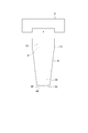
- FIG. 6 is a view of the blade holder 12 in a state where the root portion 8 of the blade 6 is fitted in the blade groove 10 as viewed from the tip side of the blade 6 along the blade length direction.
- FIG. 4 is a cross-sectional view taken along line AA in FIG. 3.
- It is a flowchart which shows an example of an electric discharge machining method. It is a figure which shows the step which positions the blade 6 in a blade groove extension direction. It is a figure which shows the step which positions the blade 6 in a blade length direction and the width direction.
- FIG. 1 It is a figure which shows the step which fixes the wing
- FIG. It is a figure which shows the step which applies a voltage between the electrode 14 and the blade
- FIG. It is a figure which shows the part 34 immersed in the process liquid 11 among the blades 6 in case the blade 6 is a turbine blade.
- an expression indicating that things such as “identical”, “equal”, and “homogeneous” are in an equal state not only represents an exactly equal state, but also has a tolerance or a difference that can provide the same function. It also represents the existing state.
- expressions representing shapes such as quadrangular shapes and cylindrical shapes represent not only geometrically strict shapes such as quadrangular shapes and cylindrical shapes, but also irregularities and chamfers as long as the same effects can be obtained. A shape including a part or the like is also expressed.
- the expressions “comprising”, “comprising”, “comprising”, “including”, or “having” one constituent element are not exclusive expressions for excluding the existence of the other constituent elements.
- FIG. 1 is a schematic diagram showing a schematic configuration of an electric discharge machining apparatus 2 according to an embodiment of the present invention.
- the electric discharge machining apparatus 2 includes a feed unit 4, a blade holder 12 that is attached to the feed unit 4 and has a blade groove 10 into which a root portion 8 of a blade 6 (workpiece) can be fitted,
- a container 13 for storing the processing liquid 11, an electrode 14 immersed in the processing liquid 11 in the container 13, and a power source 16 for applying a voltage between the blade 6 and the electrode 14 are provided.
- the blades 6 are blades attached to a rotor (not shown) of a rotary machine such as a gas turbine or a compressor.
- the feed unit 4 is configured to be able to move the blade holder 12 holding the blade 6 in three axial directions orthogonal to each other by a driving force of a motor (not shown).
- the machining liquid 11 is a dielectric liquid that fills the gap between the blade 6 and the electrode 14 in the electric discharge machining apparatus 2.
- the machining liquid 11 functions as an insulator and plays a role of maintaining an electric field through which current is ionized when a discharge occurs. Further, the machining liquid 11 flowing through the gap functions to remove machining waste from the gap.
- the processing liquid 11 for example, water whose specific resistance is adjusted to 1 to 10 ⁇ 10000 ⁇ ⁇ cm or a liquid mainly composed of oil with extremely high specific resistance is preferably used.
- the electrode 14 is preferably made of a highly conductive material such as graphite or copper. Further, a pulse power supply is preferably used as the power supply 16.
- the upper surface 44 of the electrode 14 includes a curved concave surface shape as an inverted shape of the target shape of the blade tip surface 36 of the blade 6.
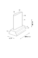
- FIG. 2 is a perspective view showing the configuration of the wing 6.
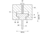
- FIG. 3 is a view of the blade holder 12 in a state where the root portion 8 of the blade 6 is fitted in the blade groove 10 as viewed from the tip side of the blade 6 along the blade length direction.
- 4 is a cross-sectional view taken along the line AA in FIG.
- the blade 6 includes a blade portion 28 having a blade-shaped cross-sectional shape and a root portion 8 for mounting on a rotor (not shown).
- the root portion 8 has a width larger than the blade thickness of the wing portion 28.
- the “width” means a width in a direction (hereinafter referred to as a width direction) orthogonal to each of the extending direction of the blade groove 10 and the blade length direction.
- the blade holder 12 presses the blade 6 toward the wall surface 20 so that the bearing surface 18 of the root portion 8 of the blade 6 contacts the wall surface 20 of the blade groove 10. It includes a bolt 22 as a positioning part.
- the bearing surface 18 is a surface that comes into contact with the rotor when the blades 6 are attached to a rotor (not shown).
- the bearing surface 18 of a typical blade 6 extends obliquely with respect to the blade length direction. Therefore, if the bearing surface 18 of the root portion 8 is brought into contact with the wall surface 20 of the blade groove 10 as described above, the blade 6 is positioned not only in the blade length direction but also in the width direction of the root portion 8 of the blade 6. Will be. Thereby, the precision of electrical discharge machining improves.
- a pair of bearing surfaces 18 are formed in the root portion 8, and the pair of bearing surfaces 18 are arranged so that the distance between the pair of bearing surfaces 18 becomes narrower toward the blade tip side. Inclined with respect to the long direction.
- the blade groove 10 is formed with a pair of wall surfaces 20 that abut against the pair of bearing surfaces 18, and the pair of wall surfaces 20 increases toward the opening side (blade tip side) of the blade groove 10. Is inclined with respect to the depth direction (blade length direction) of the blade groove 10 so that the distance between them is narrow.
- the electrical discharge machining apparatus 2 is inserted at least partially into the blade groove 10 of the blade holder 12 to extend the blade groove 10 of the root portion 8 of the blade 6. It further comprises a positioning block 26 configured to abut one end face 24 in the direction. In the exemplary form shown, the positioning block 26 is secured to the wing holder 12 by a plurality of bolts 30.
- the blade 6 can be positioned in the extending direction of the blade groove 10 by bringing the end face 24 of the root portion 8 of the blade 6 into contact with the positioning block 26. Thereby, the precision of electrical discharge machining improves.
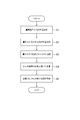
- step S1 as shown in FIG. 6, the root portion 8 of the blade 6 is inserted into the blade groove 10 of the blade holder 12, and one end surface of the root portion 8 of the blade 6 in the extending direction of the blade groove 10 is inserted. 24 is brought into contact with the positioning block 26. Thereby, the blade 6 can be positioned with respect to the blade holder 12 in the extending direction of the blade groove 10.
- step S ⁇ b> 2 the blade 6 is pressed by the bolt 22 provided on the blade holder 12 so that the bearing surface 18 of the root portion 8 contacts the wall surface 20 of the blade groove 10. . Thereby, the blade 6 can be positioned with respect to the blade holder 12 in the blade length direction and the width direction.
- step S3 the blade 6 is attached to the feed unit 4 via the blade holder 12 by fixing the blade holder 12 to the feed unit 4 of the electric discharge machining apparatus 2 as shown in FIG.
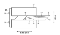
- step S4 as shown in FIG. 9, the lower surface 46 (the blade tip surface 36 in the illustrated embodiment) of the processing target portion 32 of the blade 6 is opposed to the upper surface 44 of the electrode 14 immersed in the processing liquid 11.
- the blade 6 is moved from above the electrode to the electrode 14 by the feed unit 4 so that the lower surface 46 of the processing target portion 32 of the blade 6 faces the upper surface 44 of the electrode 14 while the electrode 14 is stationary.
- Approach. In the illustrated example, only a part 34 of the blade 6 on the tip side of the root portion 8 is immersed in the machining liquid.
- step S5 a voltage is applied between the electrode 14 and the blade 6 in a state where the part 34 of the blade 6 is selectively immersed in the processing liquid 11 as shown in FIG.
- the target portion 32 is subjected to electric discharge machining.
- electric discharge machining is performed on the blade tip surface 36 of the blade 6 as the processing target portion 32.
- the blade tip surface 36 is processed into a curved convex shape as an inverted shape corresponding to the curved concave shape on the upper surface 44 of the electrode 14.
- the electric discharge machining method since electric discharge machining is performed in a state in which only a portion 34 including the machining target portion 32 of the blade 6 as a workpiece is selectively immersed in the machining liquid 11, the blade after the electric discharge machining is performed. The time and cost required for the cleaning process 6 can be reduced.
- the blade 6 is attached to the feed unit 4 of the electric discharge machining apparatus 2 to move the blade 6, so that only the part 34 of the blade 6 is selectively used. It is possible to easily realize electric discharge machining in a state immersed in the machining liquid 11. Thereby, the time and cost which the washing
- the above-described curing operation necessary for performing a grinding process which is a typical processing method of the blade tip surface 36, becomes unnecessary.
- the time and cost required for processing the blade tip surface 36 can be reduced.
- the root portion 8 when the coating is applied to the bearing surface 18 of the root portion 8 of the blade 6 for the purpose of preventing seizure, the root portion 8 does not need to be immersed in the machining liquid 11 so that the cleaning of the root portion 8 becomes unnecessary. .
- the blade 6 as a workpiece may be a moving blade in a downstream stage of a compressor of a gas turbine (not shown).
- the blades 6 are attached to the feed unit 4 of the electric discharge machining apparatus 2 while satisfying the restrictions due to the specifications of the electric discharge machining apparatus 2 by using the compressor blades in the downstream side, which is relatively lightweight, as a processing target. It becomes possible. If the blades 6 are attached to the feed unit 4 of the electric discharge machining apparatus 2, the electric discharge machining in a state where only a portion 34 including the machining target portion 32 of the blades 6 is selectively immersed in the machining liquid 11 is easy. Can be realized.
- the blade 6 as a workpiece may be a turbine blade of a gas turbine.
- the tip of the blade 6 includes the processing target portion 32 so that the processing liquid 11 does not enter the blade surface 38 of the blade 6 or the cooling hole 42 provided in the platform 40.
- the blade tip surface 36 may be subjected to electric discharge machining by being immersed in the machining liquid 11 as 34.
- the present invention is not limited to the above-described embodiments, and includes forms obtained by modifying the above-described embodiments and forms obtained by appropriately combining these forms.
- the present invention applies to a processing target portion other than the blade tip surface of the blade.
- the present invention can also be applied when electric discharge machining is performed, and can also be applied when electric discharge machining is performed on a workpiece other than a blade.
Landscapes
- Engineering & Computer Science (AREA)
- Mechanical Engineering (AREA)
- General Engineering & Computer Science (AREA)
- Chemical & Material Sciences (AREA)
- Combustion & Propulsion (AREA)
- Chemical Kinetics & Catalysis (AREA)
- Electrochemistry (AREA)
- Physics & Mathematics (AREA)
- Thermal Sciences (AREA)
- Electrical Discharge Machining, Electrochemical Machining, And Combined Machining (AREA)
- Structures Of Non-Positive Displacement Pumps (AREA)
- Turbine Rotor Nozzle Sealing (AREA)
Priority Applications (4)
| Application Number | Priority Date | Filing Date | Title |
|---|---|---|---|
| US16/339,852 US11241749B2 (en) | 2016-11-25 | 2017-10-17 | Electrical discharge machining method and electrical discharge machining device |
| CN201780057576.3A CN109715331B (zh) | 2016-11-25 | 2017-10-17 | 放电加工方法及放电加工装置 |
| KR1020197008020A KR102225716B1 (ko) | 2016-11-25 | 2017-10-17 | 방전 가공 방법 및 방전 가공 장치 |
| DE112017005989.5T DE112017005989B4 (de) | 2016-11-25 | 2017-10-17 | Funkenerodierverfahren und funkenerodiervorrichtung |
Applications Claiming Priority (2)
| Application Number | Priority Date | Filing Date | Title |
|---|---|---|---|
| JP2016-228780 | 2016-11-25 | ||
| JP2016228780A JP6747946B2 (ja) | 2016-11-25 | 2016-11-25 | 放電加工方法及び放電加工装置 |
Publications (1)
| Publication Number | Publication Date |
|---|---|
| WO2018096837A1 true WO2018096837A1 (ja) | 2018-05-31 |
Family
ID=62196177
Family Applications (1)
| Application Number | Title | Priority Date | Filing Date |
|---|---|---|---|
| PCT/JP2017/037433 Ceased WO2018096837A1 (ja) | 2016-11-25 | 2017-10-17 | 放電加工方法及び放電加工装置 |
Country Status (6)
| Country | Link |
|---|---|
| US (1) | US11241749B2 (https=) |
| JP (1) | JP6747946B2 (https=) |
| KR (1) | KR102225716B1 (https=) |
| CN (1) | CN109715331B (https=) |
| DE (1) | DE112017005989B4 (https=) |
| WO (1) | WO2018096837A1 (https=) |
Families Citing this family (3)
| Publication number | Priority date | Publication date | Assignee | Title |
|---|---|---|---|---|
| EP4481209B1 (en) * | 2023-06-19 | 2025-11-12 | Rolls-Royce plc | Fixture for components |
| KR102632888B1 (ko) * | 2023-08-25 | 2024-02-05 | 김기일 | 리버스 방전가공장치 |
| KR102907125B1 (ko) * | 2025-07-02 | 2026-01-05 | 전만복 | 전기 방전 장치 |
Citations (3)
| Publication number | Priority date | Publication date | Assignee | Title |
|---|---|---|---|---|
| JPH0373221A (ja) * | 1989-08-09 | 1991-03-28 | Shizuoka Seiki Co Ltd | 電解仕上げ加工方法 |
| JP2010100940A (ja) * | 2003-06-11 | 2010-05-06 | Ihi Corp | 機械部品の修理方法、復元機械部品の製造方法、機械部品の製造方法、及びガスタービンエンジン |
| JP2013221162A (ja) * | 2012-04-13 | 2013-10-28 | Ihi Corp | クリアランス調整ユニットセット、被覆ユニット、研削ユニット、及びクリアランス調整方法 |
Family Cites Families (29)
| Publication number | Priority date | Publication date | Assignee | Title |
|---|---|---|---|---|
| US4256555A (en) * | 1978-05-30 | 1981-03-17 | Rolls Royce Limited | Electro-chemical-machining of aerofoil blades |
| JPS591125A (ja) * | 1982-06-29 | 1984-01-06 | Kazuichi Hashiramoto | タ−ビン羽根製造法 |
| FR2570970B1 (fr) * | 1984-09-28 | 1994-06-03 | Meon Fils Ets | Procede d'usinage applique notamment aux augets de roues de turbine, les moyens et la machine de mise en oeuvre de ce procede. |
| US5091622A (en) * | 1989-05-10 | 1992-02-25 | Mitsubishi Denki K.K. | Compound machining method and apparatus |
| US5418345A (en) * | 1994-02-28 | 1995-05-23 | United Technologies Corporation | Method for forming shaped passages |
| JPH09225750A (ja) * | 1996-02-19 | 1997-09-02 | Hoden Seimitsu Kako Kenkyusho Ltd | 放電加工方法およびその装置 |
| CN2342925Y (zh) * | 1997-11-28 | 1999-10-13 | 辽宁工学院 | 非导电材料超声电解放电复合加工装置 |
| US7219408B2 (en) * | 2002-09-24 | 2007-05-22 | General Electric Company | Tool for securing a component |
| EP1544321B1 (en) * | 2002-09-24 | 2016-08-10 | IHI Corporation | Method for coating sliding surface of high temperature member |
| US6787728B2 (en) * | 2002-12-27 | 2004-09-07 | General Electric Company | Method and apparatus for near net shape rapid rough electromachining for blisks |
| GB0304321D0 (en) * | 2003-02-26 | 2003-04-02 | Bladon Jets Ltd | Fans and turbines |
| CN1826456B (zh) * | 2003-06-10 | 2011-06-15 | 株式会社Ihi | 涡轮部件、燃气涡轮发动机、涡轮部件的制造方法、表面处理方法、叶片部件、金属部件和汽轮发动机 |
| CN100405555C (zh) * | 2003-07-15 | 2008-07-23 | 株式会社荏原制作所 | 电解处理装置和电解处理方法 |
| KR200387229Y1 (ko) | 2005-03-24 | 2005-06-17 | (주)신영프레시젼 | 방전가공장치 |
| EP1870189A1 (de) * | 2006-05-31 | 2007-12-26 | Siemens Aktiengesellschaft | Verfahren zur funkenerosiven Bearbeitung eines elektrisch nicht leitenden Materials |
| US8161641B2 (en) * | 2006-07-19 | 2012-04-24 | General Electric Company | Compound electromachining |
| US20080134505A1 (en) * | 2006-12-12 | 2008-06-12 | Thomas Andrew Gabriel | Method and fixture for manufacturing components |
| US8151458B2 (en) * | 2008-02-21 | 2012-04-10 | United Technologies Corporation | Non-metallic cover for a fixture |
| US8168913B2 (en) | 2009-05-28 | 2012-05-01 | General Electric Company | Electric discharge machining die sinking device |
| FR2951101B1 (fr) * | 2009-10-08 | 2011-11-18 | Snecma | Procede et dispositif de percage d' une piece d'une turbomachine |
| CN101704142B (zh) * | 2009-11-19 | 2011-07-20 | 沈阳黎明航空发动机(集团)有限责任公司 | 一种钛合金大尺寸叶片电解加工方法 |
| CN103056462B (zh) * | 2011-10-24 | 2015-04-08 | 沈阳黎明航空发动机(集团)有限责任公司 | 一种叶片型面电解阴极模具保护装置的设计方法 |
| CN103624350B (zh) * | 2013-11-21 | 2017-01-04 | 南京航空航天大学 | 一种整体叶盘叶片电解精加工成形装置及其整体叶盘叶片加工成形方法 |
| CN104708131B (zh) * | 2013-12-13 | 2018-06-29 | 通用电气公司 | 加工装置和加工方法 |
| US9737945B2 (en) * | 2014-03-27 | 2017-08-22 | Mitsubishi Electric Corporation | Electrical discharge machining apparatus |
| CN205096674U (zh) * | 2015-10-13 | 2016-03-23 | 哈尔滨理工大学 | 一种电火花成型加工用工具和工件电极的装夹装置 |
| CN105397218A (zh) * | 2015-12-08 | 2016-03-16 | 四川成发航空科技股份有限公司 | 航空发动机导向叶片封严槽的电火花加工方法 |
| CN106077859A (zh) * | 2016-06-30 | 2016-11-09 | 徐工集团工程机械有限公司 | 去除金属工件毛刺的方法及装置 |
| US10677067B2 (en) * | 2016-09-29 | 2020-06-09 | General Electric Company | Airfoil and method of assembling same |
-
2016
- 2016-11-25 JP JP2016228780A patent/JP6747946B2/ja active Active
-
2017
- 2017-10-17 CN CN201780057576.3A patent/CN109715331B/zh active Active
- 2017-10-17 WO PCT/JP2017/037433 patent/WO2018096837A1/ja not_active Ceased
- 2017-10-17 KR KR1020197008020A patent/KR102225716B1/ko active Active
- 2017-10-17 DE DE112017005989.5T patent/DE112017005989B4/de active Active
- 2017-10-17 US US16/339,852 patent/US11241749B2/en active Active
Patent Citations (3)
| Publication number | Priority date | Publication date | Assignee | Title |
|---|---|---|---|---|
| JPH0373221A (ja) * | 1989-08-09 | 1991-03-28 | Shizuoka Seiki Co Ltd | 電解仕上げ加工方法 |
| JP2010100940A (ja) * | 2003-06-11 | 2010-05-06 | Ihi Corp | 機械部品の修理方法、復元機械部品の製造方法、機械部品の製造方法、及びガスタービンエンジン |
| JP2013221162A (ja) * | 2012-04-13 | 2013-10-28 | Ihi Corp | クリアランス調整ユニットセット、被覆ユニット、研削ユニット、及びクリアランス調整方法 |
Also Published As
| Publication number | Publication date |
|---|---|
| JP6747946B2 (ja) | 2020-08-26 |
| DE112017005989T5 (de) | 2019-08-08 |
| DE112017005989B4 (de) | 2025-05-22 |
| CN109715331A (zh) | 2019-05-03 |
| KR20190042041A (ko) | 2019-04-23 |
| US11241749B2 (en) | 2022-02-08 |
| JP2018083265A (ja) | 2018-05-31 |
| KR102225716B1 (ko) | 2021-03-09 |
| US20190291197A1 (en) | 2019-09-26 |
| CN109715331B (zh) | 2020-08-04 |
Similar Documents
| Publication | Publication Date | Title |
|---|---|---|
| WO2018096837A1 (ja) | 放電加工方法及び放電加工装置 | |
| CN110480365A (zh) | 车削加工机床及车削加工方法 | |
| JP6855369B2 (ja) | 電気加工装置および方法 | |
| JP4923132B2 (ja) | ホイールホルダおよびその製造方法およびホイールホルダを用いたカッターホイール保持機構 | |
| CN113677470A (zh) | 线放电加工机 | |
| TWI604905B (zh) | 難加工材料之放電輔助切削加工裝置 | |
| CN112475491A (zh) | 一种适用于绝缘硬脆性材料的双极性电极电火花加工装置及方法 | |
| CN204747693U (zh) | 一种电火花磨削磨轮主轴装置 | |
| US20170368626A1 (en) | Electrochemical Removal Of Material From A Workpiece | |
| KR20130005613U (ko) | 초음파 주축의 전기적 접점 구조 | |
| CN218487397U (zh) | 放电加工装置 | |
| CN206912416U (zh) | 一种应用于电火花加工的设备 | |
| KR101510043B1 (ko) | 전해연마 장치 | |
| CN107598311A (zh) | 一种旋转式叠层电极放电加工装置及方法 | |
| WO2018145260A1 (en) | Electromachining systems and methods | |
| TWM652923U (zh) | 放電加工裝置 | |
| JP2007021707A (ja) | 超音波コレット | |
| CN207508463U (zh) | 一种旋转式叠层电极放电加工装置 | |
| TW201811473A (zh) | 電化學放電加工裝置 | |
| JP5635768B2 (ja) | 電流による工作機械の工具損傷を防止するための加工材締付け装置 | |
| TWI913763B (zh) | 放電加工裝置 | |
| US12472570B2 (en) | Electrical discharge machining apparatus | |
| CN206912427U (zh) | 用于电火花加工的多用途夹具 | |
| CN106944683B (zh) | 一种工具电极自动补偿的放电车削加工装置及方法 | |
| Vijay et al. | Investigations on Electrochemical Discharge Machining of Al2O3 Ceramics |
Legal Events
| Date | Code | Title | Description |
|---|---|---|---|
| 121 | Ep: the epo has been informed by wipo that ep was designated in this application |
Ref document number: 17873458 Country of ref document: EP Kind code of ref document: A1 |
|
| ENP | Entry into the national phase |
Ref document number: 20197008020 Country of ref document: KR Kind code of ref document: A |
|
| 122 | Ep: pct application non-entry in european phase |
Ref document number: 17873458 Country of ref document: EP Kind code of ref document: A1 |
|
| WWG | Wipo information: grant in national office |
Ref document number: 112017005989 Country of ref document: DE |