WO2018096837A1 - Electrical discharge machining method and electrical discharge machining device - Google Patents
Electrical discharge machining method and electrical discharge machining device Download PDFInfo
- Publication number
- WO2018096837A1 WO2018096837A1 PCT/JP2017/037433 JP2017037433W WO2018096837A1 WO 2018096837 A1 WO2018096837 A1 WO 2018096837A1 JP 2017037433 W JP2017037433 W JP 2017037433W WO 2018096837 A1 WO2018096837 A1 WO 2018096837A1
- Authority
- WO
- WIPO (PCT)
- Prior art keywords
- blade
- electric discharge
- discharge machining
- workpiece
- machining
- Prior art date
Links
Images


Classifications
-
- F—MECHANICAL ENGINEERING; LIGHTING; HEATING; WEAPONS; BLASTING
- F01—MACHINES OR ENGINES IN GENERAL; ENGINE PLANTS IN GENERAL; STEAM ENGINES
- F01D—NON-POSITIVE DISPLACEMENT MACHINES OR ENGINES, e.g. STEAM TURBINES
- F01D25/00—Component parts, details, or accessories, not provided for in, or of interest apart from, other groups
- F01D25/28—Supporting or mounting arrangements, e.g. for turbine casing
- F01D25/285—Temporary support structures, e.g. for testing, assembling, installing, repairing; Assembly methods using such structures
-
- B—PERFORMING OPERATIONS; TRANSPORTING
- B23—MACHINE TOOLS; METAL-WORKING NOT OTHERWISE PROVIDED FOR
- B23H—WORKING OF METAL BY THE ACTION OF A HIGH CONCENTRATION OF ELECTRIC CURRENT ON A WORKPIECE USING AN ELECTRODE WHICH TAKES THE PLACE OF A TOOL; SUCH WORKING COMBINED WITH OTHER FORMS OF WORKING OF METAL
- B23H7/00—Processes or apparatus applicable to both electrical discharge machining and electrochemical machining
-
- B—PERFORMING OPERATIONS; TRANSPORTING
- B23—MACHINE TOOLS; METAL-WORKING NOT OTHERWISE PROVIDED FOR
- B23H—WORKING OF METAL BY THE ACTION OF A HIGH CONCENTRATION OF ELECTRIC CURRENT ON A WORKPIECE USING AN ELECTRODE WHICH TAKES THE PLACE OF A TOOL; SUCH WORKING COMBINED WITH OTHER FORMS OF WORKING OF METAL
- B23H1/00—Electrical discharge machining, i.e. removing metal with a series of rapidly recurring electrical discharges between an electrode and a workpiece in the presence of a fluid dielectric
-
- B—PERFORMING OPERATIONS; TRANSPORTING
- B23—MACHINE TOOLS; METAL-WORKING NOT OTHERWISE PROVIDED FOR
- B23H—WORKING OF METAL BY THE ACTION OF A HIGH CONCENTRATION OF ELECTRIC CURRENT ON A WORKPIECE USING AN ELECTRODE WHICH TAKES THE PLACE OF A TOOL; SUCH WORKING COMBINED WITH OTHER FORMS OF WORKING OF METAL
- B23H7/00—Processes or apparatus applicable to both electrical discharge machining and electrochemical machining
- B23H7/22—Electrodes specially adapted therefor or their manufacture
-
- B—PERFORMING OPERATIONS; TRANSPORTING
- B23—MACHINE TOOLS; METAL-WORKING NOT OTHERWISE PROVIDED FOR
- B23H—WORKING OF METAL BY THE ACTION OF A HIGH CONCENTRATION OF ELECTRIC CURRENT ON A WORKPIECE USING AN ELECTRODE WHICH TAKES THE PLACE OF A TOOL; SUCH WORKING COMBINED WITH OTHER FORMS OF WORKING OF METAL
- B23H7/00—Processes or apparatus applicable to both electrical discharge machining and electrochemical machining
- B23H7/26—Apparatus for moving or positioning electrode relatively to workpiece; Mounting of electrode
-
- B—PERFORMING OPERATIONS; TRANSPORTING
- B23—MACHINE TOOLS; METAL-WORKING NOT OTHERWISE PROVIDED FOR
- B23H—WORKING OF METAL BY THE ACTION OF A HIGH CONCENTRATION OF ELECTRIC CURRENT ON A WORKPIECE USING AN ELECTRODE WHICH TAKES THE PLACE OF A TOOL; SUCH WORKING COMBINED WITH OTHER FORMS OF WORKING OF METAL
- B23H9/00—Machining specially adapted for treating particular metal objects or for obtaining special effects or results on metal objects
- B23H9/10—Working turbine blades or nozzles
-
- F—MECHANICAL ENGINEERING; LIGHTING; HEATING; WEAPONS; BLASTING
- F01—MACHINES OR ENGINES IN GENERAL; ENGINE PLANTS IN GENERAL; STEAM ENGINES
- F01D—NON-POSITIVE DISPLACEMENT MACHINES OR ENGINES, e.g. STEAM TURBINES
- F01D25/00—Component parts, details, or accessories, not provided for in, or of interest apart from, other groups
-
- F—MECHANICAL ENGINEERING; LIGHTING; HEATING; WEAPONS; BLASTING
- F01—MACHINES OR ENGINES IN GENERAL; ENGINE PLANTS IN GENERAL; STEAM ENGINES
- F01D—NON-POSITIVE DISPLACEMENT MACHINES OR ENGINES, e.g. STEAM TURBINES
- F01D5/00—Blades; Blade-carrying members; Heating, heat-insulating, cooling or antivibration means on the blades or the members
- F01D5/12—Blades
- F01D5/14—Form or construction
-
- F—MECHANICAL ENGINEERING; LIGHTING; HEATING; WEAPONS; BLASTING
- F01—MACHINES OR ENGINES IN GENERAL; ENGINE PLANTS IN GENERAL; STEAM ENGINES
- F01D—NON-POSITIVE DISPLACEMENT MACHINES OR ENGINES, e.g. STEAM TURBINES
- F01D9/00—Stators
- F01D9/02—Nozzles; Nozzle boxes; Stator blades; Guide conduits, e.g. individual nozzles
-
- F—MECHANICAL ENGINEERING; LIGHTING; HEATING; WEAPONS; BLASTING
- F02—COMBUSTION ENGINES; HOT-GAS OR COMBUSTION-PRODUCT ENGINE PLANTS
- F02C—GAS-TURBINE PLANTS; AIR INTAKES FOR JET-PROPULSION PLANTS; CONTROLLING FUEL SUPPLY IN AIR-BREATHING JET-PROPULSION PLANTS
- F02C7/00—Features, components parts, details or accessories, not provided for in, or of interest apart form groups F02C1/00 - F02C6/00; Air intakes for jet-propulsion plants
-
- F—MECHANICAL ENGINEERING; LIGHTING; HEATING; WEAPONS; BLASTING
- F04—POSITIVE - DISPLACEMENT MACHINES FOR LIQUIDS; PUMPS FOR LIQUIDS OR ELASTIC FLUIDS
- F04D—NON-POSITIVE-DISPLACEMENT PUMPS
- F04D29/00—Details, component parts, or accessories
- F04D29/26—Rotors specially for elastic fluids
- F04D29/32—Rotors specially for elastic fluids for axial flow pumps
- F04D29/38—Blades
-
- F—MECHANICAL ENGINEERING; LIGHTING; HEATING; WEAPONS; BLASTING
- F05—INDEXING SCHEMES RELATING TO ENGINES OR PUMPS IN VARIOUS SUBCLASSES OF CLASSES F01-F04
- F05D—INDEXING SCHEME FOR ASPECTS RELATING TO NON-POSITIVE-DISPLACEMENT MACHINES OR ENGINES, GAS-TURBINES OR JET-PROPULSION PLANTS
- F05D2220/00—Application
- F05D2220/30—Application in turbines
- F05D2220/32—Application in turbines in gas turbines
- F05D2220/321—Application in turbines in gas turbines for a special turbine stage
- F05D2220/3216—Application in turbines in gas turbines for a special turbine stage for a special compressor stage
- F05D2220/3219—Application in turbines in gas turbines for a special turbine stage for a special compressor stage for the last stage of a compressor or a high pressure compressor
-
- F—MECHANICAL ENGINEERING; LIGHTING; HEATING; WEAPONS; BLASTING
- F05—INDEXING SCHEMES RELATING TO ENGINES OR PUMPS IN VARIOUS SUBCLASSES OF CLASSES F01-F04
- F05D—INDEXING SCHEME FOR ASPECTS RELATING TO NON-POSITIVE-DISPLACEMENT MACHINES OR ENGINES, GAS-TURBINES OR JET-PROPULSION PLANTS
- F05D2230/00—Manufacture
- F05D2230/10—Manufacture by removing material
- F05D2230/12—Manufacture by removing material by spark erosion methods
-
- F—MECHANICAL ENGINEERING; LIGHTING; HEATING; WEAPONS; BLASTING
- F05—INDEXING SCHEMES RELATING TO ENGINES OR PUMPS IN VARIOUS SUBCLASSES OF CLASSES F01-F04
- F05D—INDEXING SCHEME FOR ASPECTS RELATING TO NON-POSITIVE-DISPLACEMENT MACHINES OR ENGINES, GAS-TURBINES OR JET-PROPULSION PLANTS
- F05D2230/00—Manufacture
- F05D2230/60—Assembly methods
- F05D2230/68—Assembly methods using auxiliary equipment for lifting or holding
Definitions
- the present disclosure relates to an electric discharge machining method and an electric discharge machining apparatus.
- a grinding apparatus or a polishing apparatus may be used.
- the tip surface of a blade used in a rotary machine such as a gas turbine or a compressor is typically processed by grinding the blade tip surface with an abrasive such as sand paper.
- an abrasive such as sand paper.
- the processing accuracy tends to be low, and in order to protect the blade from chips generated by grinding, it is necessary to cure the portion other than the tip surface of the blade. It takes a lot of work time.
- Patent Document 1 discloses a method of machining a blade shape of a turbine blade as a workpiece using an electric discharge machining apparatus instead of a grinding machine or a polishing machine.
- a pair of electrodes is fixed in the machining liquid, and the blades of the turbine blade move in the horizontal direction between the electrodes to perform electric discharge machining.
- At least one embodiment of the present invention has been made in view of the above-described conventional problems, and an object of the present invention is to provide an electric discharge capable of reducing the time and cost required for a workpiece cleaning process after electric discharge machining.
- a machining method and an electrical discharge machining apparatus are provided.
- the electric discharge machining method selects only a part of the workpiece including the machining target portion so that the machining target portion of the workpiece faces the electrode immersed in the machining liquid.
- the method further includes a step of attaching the workpiece to a feeding unit of an electric discharge machine, and in the step of immersing the workpiece in the machining liquid, The workpiece is brought close to the electrode by the feeding unit while being kept stationary.
- the workpiece is attached to the feeding unit of the electric discharge machine and the workpiece is moved. It is possible to easily realize electric discharge machining in a state where only the part is selectively immersed in the machining liquid. As a result, as described in (1) above, it is possible to reduce the time and cost required for the workpiece cleaning process after electric discharge machining.
- the lower surface of the workpiece portion of the workpiece is disposed on the upper surface of the electrode.
- the workpiece is caused to approach the electrode from above the electrode by the feeding unit so as to face each other.
- the tip surface of a blade used in a rotating machine such as a gas turbine or a compressor is typically processed by grinding the blade tip surface with an abrasive such as sand paper.
- an abrasive such as sand paper.
- the curing work necessary for carrying out the grinding process which is a typical blade blade surface machining method, by performing electric discharge machining on the blade tip surface having a desired shape. Can be eliminated, and the time and cost required for processing the blade tip surface can be reduced.
- wing after electric discharge machining requires can be reduced.
- the electric discharge machining method described in the above (5) for example, when a coating is applied to the bearing surface of the root portion of the blade for the purpose of preventing seizure, by not immersing the root portion in the machining liquid, Cleaning of the root part is not necessary.
- the workpiece is a gas turbine blade
- only the tip of the gas turbine blade is used as the machining liquid so that the machining liquid does not enter the cooling hole provided on the blade surface of the gas turbine blade or the platform.
- the tip of the gas turbine blade may be immersed and subjected to electric discharge machining.
- the blade is a moving blade in a downstream stage of a compressor of a gas turbine.
- the electric discharge machine of the electric discharge machine is satisfied while satisfying the restrictions caused by the specifications of the electric discharge machine.
- a work (wing) can be attached to the feed unit. If the workpiece (blade) is attached to the feeding unit of the electric discharge machine, electric discharge machining can be easily realized in a state where only the part of the workpiece is selectively immersed in the machining liquid.
- a root portion of the blade is fitted into a blade groove of the blade holder, and the blade holder
- the step of attaching the blade to the feed unit of the electric discharge machine via the step of immersing the blade in the machining liquid causes the blade to approach the electrode by the feed unit while keeping the electrode stationary.
- a blade (work) is attached to the feed unit of the electric discharge machine to move the blade.
- the electric discharge machining can be easily realized in a state where only a part of the blade is selectively immersed in the machining liquid. As a result, as described in (1) above, it is possible to reduce the time and cost required for the blade cleaning step after electric discharge machining.
- the positioning unit provided in the blade holder may be configured so that the bearing surface of the root portion contacts the wall surface of the blade groove.
- the method further includes the step of pressing the wing.
- the blade can be positioned with respect to the blade holder at least in the blade length direction by bringing the bearing surface of the root portion into contact with the wall surface of the blade groove.
- the precision of electrical discharge machining improves.
- the bearing surface of a typical blade extends obliquely with respect to the blade length direction, if the root bearing surface is brought into contact with the wall surface of the blade groove as described above, the blade length direction
- the blade is positioned not only in the width direction of the blade root portion. Thereby, the precision of electrical discharge machining improves.
- one end surface of the root portion of the blade in the extending direction of the blade groove is formed into the blade groove.
- the method further includes a step of contacting the inserted positioning block.
- the blade can be positioned in the blade groove extending direction by bringing one end surface of the root portion of the blade into contact with the positioning block. Thereby, the precision of electrical discharge machining improves.
- An electric discharge machining apparatus for a blade includes a feed unit, a blade holder attached to the feed unit and having a blade groove into which a root portion of the blade can be fitted, An electrode immersed in the liquid; and a power source for applying a voltage between the blade and the electrode.
- the blade holder is configured such that the blade is attached to the wall surface such that a bearing surface of the root portion contacts the wall surface of the blade groove.
- the positioning part for pressing toward is included.
- the blade can be positioned with respect to the blade holder at least in the blade length direction by bringing the bearing surface of the root portion into contact with the wall surface of the blade groove.
- the precision of electrical discharge machining improves.
- the bearing surface of a typical blade extends obliquely with respect to the blade length direction, if the root bearing surface is brought into contact with the wall surface of the blade groove as described above, the blade length direction
- the blade is positioned not only in the width direction of the blade root portion. Thereby, the precision of electrical discharge machining improves.
- the wing holder is at least partially inserted into the blade groove, and the root portion of the blade is It further includes a positioning block configured to contact one end surface in the extending direction of the blade groove.
- the blade can be positioned in the blade groove extending direction by bringing one end face of the blade root portion into contact with the positioning block. Therefore, the precision of electrical discharge machining improves.
- the upper surface of the electrode includes a curved concave shape.
- an electric discharge machining method and an electric discharge machining apparatus capable of reducing the time and cost required for a workpiece cleaning process after electric discharge machining.
- FIG. 6 is a perspective view showing a configuration of a wing 6.
- FIG. 6 is a view of the blade holder 12 in a state where the root portion 8 of the blade 6 is fitted in the blade groove 10 as viewed from the tip side of the blade 6 along the blade length direction.
- FIG. 4 is a cross-sectional view taken along line AA in FIG. 3.
- It is a flowchart which shows an example of an electric discharge machining method. It is a figure which shows the step which positions the blade 6 in a blade groove extension direction. It is a figure which shows the step which positions the blade 6 in a blade length direction and the width direction.
- FIG. 1 It is a figure which shows the step which fixes the wing
- FIG. It is a figure which shows the step which applies a voltage between the electrode 14 and the blade
- FIG. It is a figure which shows the part 34 immersed in the process liquid 11 among the blades 6 in case the blade 6 is a turbine blade.
- an expression indicating that things such as “identical”, “equal”, and “homogeneous” are in an equal state not only represents an exactly equal state, but also has a tolerance or a difference that can provide the same function. It also represents the existing state.
- expressions representing shapes such as quadrangular shapes and cylindrical shapes represent not only geometrically strict shapes such as quadrangular shapes and cylindrical shapes, but also irregularities and chamfers as long as the same effects can be obtained. A shape including a part or the like is also expressed.
- the expressions “comprising”, “comprising”, “comprising”, “including”, or “having” one constituent element are not exclusive expressions for excluding the existence of the other constituent elements.
- FIG. 1 is a schematic diagram showing a schematic configuration of an electric discharge machining apparatus 2 according to an embodiment of the present invention.
- the electric discharge machining apparatus 2 includes a feed unit 4, a blade holder 12 that is attached to the feed unit 4 and has a blade groove 10 into which a root portion 8 of a blade 6 (workpiece) can be fitted,
- a container 13 for storing the processing liquid 11, an electrode 14 immersed in the processing liquid 11 in the container 13, and a power source 16 for applying a voltage between the blade 6 and the electrode 14 are provided.
- the blades 6 are blades attached to a rotor (not shown) of a rotary machine such as a gas turbine or a compressor.
- the feed unit 4 is configured to be able to move the blade holder 12 holding the blade 6 in three axial directions orthogonal to each other by a driving force of a motor (not shown).
- the machining liquid 11 is a dielectric liquid that fills the gap between the blade 6 and the electrode 14 in the electric discharge machining apparatus 2.
- the machining liquid 11 functions as an insulator and plays a role of maintaining an electric field through which current is ionized when a discharge occurs. Further, the machining liquid 11 flowing through the gap functions to remove machining waste from the gap.
- the processing liquid 11 for example, water whose specific resistance is adjusted to 1 to 10 ⁇ 10000 ⁇ ⁇ cm or a liquid mainly composed of oil with extremely high specific resistance is preferably used.
- the electrode 14 is preferably made of a highly conductive material such as graphite or copper. Further, a pulse power supply is preferably used as the power supply 16.
- the upper surface 44 of the electrode 14 includes a curved concave surface shape as an inverted shape of the target shape of the blade tip surface 36 of the blade 6.
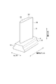
- FIG. 2 is a perspective view showing the configuration of the wing 6.
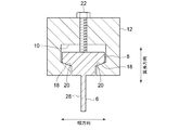
- FIG. 3 is a view of the blade holder 12 in a state where the root portion 8 of the blade 6 is fitted in the blade groove 10 as viewed from the tip side of the blade 6 along the blade length direction.
- 4 is a cross-sectional view taken along the line AA in FIG.
- the blade 6 includes a blade portion 28 having a blade-shaped cross-sectional shape and a root portion 8 for mounting on a rotor (not shown).
- the root portion 8 has a width larger than the blade thickness of the wing portion 28.
- the “width” means a width in a direction (hereinafter referred to as a width direction) orthogonal to each of the extending direction of the blade groove 10 and the blade length direction.
- the blade holder 12 presses the blade 6 toward the wall surface 20 so that the bearing surface 18 of the root portion 8 of the blade 6 contacts the wall surface 20 of the blade groove 10. It includes a bolt 22 as a positioning part.
- the bearing surface 18 is a surface that comes into contact with the rotor when the blades 6 are attached to a rotor (not shown).
- the bearing surface 18 of a typical blade 6 extends obliquely with respect to the blade length direction. Therefore, if the bearing surface 18 of the root portion 8 is brought into contact with the wall surface 20 of the blade groove 10 as described above, the blade 6 is positioned not only in the blade length direction but also in the width direction of the root portion 8 of the blade 6. Will be. Thereby, the precision of electrical discharge machining improves.
- a pair of bearing surfaces 18 are formed in the root portion 8, and the pair of bearing surfaces 18 are arranged so that the distance between the pair of bearing surfaces 18 becomes narrower toward the blade tip side. Inclined with respect to the long direction.
- the blade groove 10 is formed with a pair of wall surfaces 20 that abut against the pair of bearing surfaces 18, and the pair of wall surfaces 20 increases toward the opening side (blade tip side) of the blade groove 10. Is inclined with respect to the depth direction (blade length direction) of the blade groove 10 so that the distance between them is narrow.
- the electrical discharge machining apparatus 2 is inserted at least partially into the blade groove 10 of the blade holder 12 to extend the blade groove 10 of the root portion 8 of the blade 6. It further comprises a positioning block 26 configured to abut one end face 24 in the direction. In the exemplary form shown, the positioning block 26 is secured to the wing holder 12 by a plurality of bolts 30.
- the blade 6 can be positioned in the extending direction of the blade groove 10 by bringing the end face 24 of the root portion 8 of the blade 6 into contact with the positioning block 26. Thereby, the precision of electrical discharge machining improves.
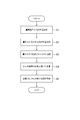
- step S1 as shown in FIG. 6, the root portion 8 of the blade 6 is inserted into the blade groove 10 of the blade holder 12, and one end surface of the root portion 8 of the blade 6 in the extending direction of the blade groove 10 is inserted. 24 is brought into contact with the positioning block 26. Thereby, the blade 6 can be positioned with respect to the blade holder 12 in the extending direction of the blade groove 10.
- step S ⁇ b> 2 the blade 6 is pressed by the bolt 22 provided on the blade holder 12 so that the bearing surface 18 of the root portion 8 contacts the wall surface 20 of the blade groove 10. . Thereby, the blade 6 can be positioned with respect to the blade holder 12 in the blade length direction and the width direction.
- step S3 the blade 6 is attached to the feed unit 4 via the blade holder 12 by fixing the blade holder 12 to the feed unit 4 of the electric discharge machining apparatus 2 as shown in FIG.
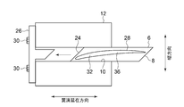
- step S4 as shown in FIG. 9, the lower surface 46 (the blade tip surface 36 in the illustrated embodiment) of the processing target portion 32 of the blade 6 is opposed to the upper surface 44 of the electrode 14 immersed in the processing liquid 11.
- the blade 6 is moved from above the electrode to the electrode 14 by the feed unit 4 so that the lower surface 46 of the processing target portion 32 of the blade 6 faces the upper surface 44 of the electrode 14 while the electrode 14 is stationary.
- Approach. In the illustrated example, only a part 34 of the blade 6 on the tip side of the root portion 8 is immersed in the machining liquid.
- step S5 a voltage is applied between the electrode 14 and the blade 6 in a state where the part 34 of the blade 6 is selectively immersed in the processing liquid 11 as shown in FIG.
- the target portion 32 is subjected to electric discharge machining.
- electric discharge machining is performed on the blade tip surface 36 of the blade 6 as the processing target portion 32.
- the blade tip surface 36 is processed into a curved convex shape as an inverted shape corresponding to the curved concave shape on the upper surface 44 of the electrode 14.
- the electric discharge machining method since electric discharge machining is performed in a state in which only a portion 34 including the machining target portion 32 of the blade 6 as a workpiece is selectively immersed in the machining liquid 11, the blade after the electric discharge machining is performed. The time and cost required for the cleaning process 6 can be reduced.
- the blade 6 is attached to the feed unit 4 of the electric discharge machining apparatus 2 to move the blade 6, so that only the part 34 of the blade 6 is selectively used. It is possible to easily realize electric discharge machining in a state immersed in the machining liquid 11. Thereby, the time and cost which the washing
- the above-described curing operation necessary for performing a grinding process which is a typical processing method of the blade tip surface 36, becomes unnecessary.
- the time and cost required for processing the blade tip surface 36 can be reduced.
- the root portion 8 when the coating is applied to the bearing surface 18 of the root portion 8 of the blade 6 for the purpose of preventing seizure, the root portion 8 does not need to be immersed in the machining liquid 11 so that the cleaning of the root portion 8 becomes unnecessary. .
- the blade 6 as a workpiece may be a moving blade in a downstream stage of a compressor of a gas turbine (not shown).
- the blades 6 are attached to the feed unit 4 of the electric discharge machining apparatus 2 while satisfying the restrictions due to the specifications of the electric discharge machining apparatus 2 by using the compressor blades in the downstream side, which is relatively lightweight, as a processing target. It becomes possible. If the blades 6 are attached to the feed unit 4 of the electric discharge machining apparatus 2, the electric discharge machining in a state where only a portion 34 including the machining target portion 32 of the blades 6 is selectively immersed in the machining liquid 11 is easy. Can be realized.
- the blade 6 as a workpiece may be a turbine blade of a gas turbine.
- the tip of the blade 6 includes the processing target portion 32 so that the processing liquid 11 does not enter the blade surface 38 of the blade 6 or the cooling hole 42 provided in the platform 40.
- the blade tip surface 36 may be subjected to electric discharge machining by being immersed in the machining liquid 11 as 34.
- the present invention is not limited to the above-described embodiments, and includes forms obtained by modifying the above-described embodiments and forms obtained by appropriately combining these forms.
- the present invention applies to a processing target portion other than the blade tip surface of the blade.
- the present invention can also be applied when electric discharge machining is performed, and can also be applied when electric discharge machining is performed on a workpiece other than a blade.
Landscapes
- Engineering & Computer Science (AREA)
- Mechanical Engineering (AREA)
- General Engineering & Computer Science (AREA)
- Chemical & Material Sciences (AREA)
- Combustion & Propulsion (AREA)
- Chemical Kinetics & Catalysis (AREA)
- Electrochemistry (AREA)
- Physics & Mathematics (AREA)
- Thermal Sciences (AREA)
- Electrical Discharge Machining, Electrochemical Machining, And Combined Machining (AREA)
- Turbine Rotor Nozzle Sealing (AREA)
- Structures Of Non-Positive Displacement Pumps (AREA)
Abstract
An electrical discharge machining method provided with a step for selectively immersing only a portion of a work piece that includes a machining object part in a machining fluid so that the machining object part of the work piece faces an electrode immersed in the machining fluid, and a step for applying a voltage between the electrode and the work piece and performing electrical discharge machining on the machining object part in a state in which the portion of the work piece is selectively immersed in the machining fluid.
Description
本開示は、放電加工方法及び放電加工装置に関する。
The present disclosure relates to an electric discharge machining method and an electric discharge machining apparatus.
従来、ワーク(被工作物)を加工するために、研削加工装置や研磨加工装置が使用される場合がある。例えば、ガスタービンや圧縮機等の回転機械に用いられる翼のチップ面は、典型的には、翼チップ面をサンドペーパ等の研削材により研削することで加工される。しかしながら、研削加工装置や研磨加工装置を使用する場合、加工精度が低くなりやすく、また、研削により生じた切粉から翼を保護するために、翼のうちチップ面以外の部位を養生する必要があり、多大な作業時間を要してしまう。
Conventionally, in order to process a workpiece (workpiece), a grinding apparatus or a polishing apparatus may be used. For example, the tip surface of a blade used in a rotary machine such as a gas turbine or a compressor is typically processed by grinding the blade tip surface with an abrasive such as sand paper. However, when using a grinding device or polishing device, the processing accuracy tends to be low, and in order to protect the blade from chips generated by grinding, it is necessary to cure the portion other than the tip surface of the blade. It takes a lot of work time.
特許文献1には、研削加工装置や研磨加工装置ではなく、放電加工装置を用いてワークとしてのタービンブレードの翼形状を加工する方法が開示されている。特許文献1に記載の加工方法では、加工液中に一対の電極が固定されており、その電極間をタービンブレードの翼が水平方向に移動して放電加工が行われる。
Patent Document 1 discloses a method of machining a blade shape of a turbine blade as a workpiece using an electric discharge machining apparatus instead of a grinding machine or a polishing machine. In the machining method described in Patent Document 1, a pair of electrodes is fixed in the machining liquid, and the blades of the turbine blade move in the horizontal direction between the electrodes to perform electric discharge machining.
特許文献1に記載される放電加工方法では、ワーク全体が加工液中に浸漬された状態で放電加工が行われる。このため、放電加工後におけるワークの洗浄工程に多大な時間及びコストを要してしまう。
In the electric discharge machining method described in Patent Document 1, electric discharge machining is performed in a state where the entire workpiece is immersed in the machining fluid. For this reason, much time and cost are required for the cleaning process of the work after electric discharge machining.
本発明の少なくとも一実施形態は、上述したような従来の課題に鑑みなされたものであって、その目的とするところは、放電加工後におけるワークの洗浄工程に要する時間及びコストを低減可能な放電加工方法及び放電加工装置を提供することである。
At least one embodiment of the present invention has been made in view of the above-described conventional problems, and an object of the present invention is to provide an electric discharge capable of reducing the time and cost required for a workpiece cleaning process after electric discharge machining. A machining method and an electrical discharge machining apparatus are provided.
(1)本発明の少なくとも一実施形態に係る放電加工方法は、加工液に浸漬された電極にワークの加工対象部が対向するように、前記ワークのうち前記加工対象部を含む一部分のみを選択的に前記加工液に浸漬させるステップと、前記ワークのうち前記加工対象部を含む前記一部分を選択的に前記加工液に浸漬した状態で、前記電極と前記ワークとの間に電圧を印加して前記加工対象部に放電加工を施すステップと、を備える。
(1) The electric discharge machining method according to at least one embodiment of the present invention selects only a part of the workpiece including the machining target portion so that the machining target portion of the workpiece faces the electrode immersed in the machining liquid. A step of immersing the workpiece in the machining liquid, and applying a voltage between the electrode and the workpiece in a state where the part of the workpiece including the portion to be machined is selectively immersed in the machining fluid. Applying electrical discharge machining to the machining target portion.
上記(1)に記載の放電加工方法によれば、ワークのうち加工対象部を含む一部分のみを選択的に加工液に浸漬した状態で放電加工を行うようにしたので、放電加工後におけるワークの洗浄工程に要する時間及びコストを低減することができる。なお、上記(1)において、「前記ワークのうち前記加工対象部を含む一部分のみを選択的に前記加工液に浸漬させる」とは、ワークのうち加工対象部を含む一部分を加工液に浸漬させ、ワークのうち加工対象部を含む一部分以外を加工液に浸漬させないことを意味する。
According to the electric discharge machining method described in (1) above, since electric discharge machining is performed in a state in which only a part of the workpiece including the machining target portion is selectively immersed in the machining liquid, The time and cost required for the cleaning process can be reduced. In the above (1), “selectively immersing only a part of the workpiece including the processing target part in the processing liquid” means immersing a part of the work including the processing target part in the processing liquid. This means that the part other than the part including the processing target portion of the workpiece is not immersed in the processing liquid.
(2)幾つかの実施形態では、上記(1)に記載の放電加工方法において、前記ワークを放電加工機の送りユニットに取り付けるステップをさらに備え、前記加工液に浸漬させるステップでは、前記電極を静止させたまま、前記送りユニットにより前記ワークを前記電極に対して接近させる。
(2) In some embodiments, in the electric discharge machining method according to (1), the method further includes a step of attaching the workpiece to a feeding unit of an electric discharge machine, and in the step of immersing the workpiece in the machining liquid, The workpiece is brought close to the electrode by the feeding unit while being kept stationary.
上記(2)に記載の放電加工方法によれば、典型的な放電加工方法とは異なり、放電加工機の送りユニットに電極ではなくワークを取り付けて、ワークを移動させるようにしたので、ワークの上記一部分のみを選択的に加工液に浸漬させた状態での放電加工を容易に実現できる。これにより、上記(1)で述べたように、放電加工後におけるワークの洗浄工程に要する時間及びコストを低減可能となる。
According to the electric discharge machining method described in the above (2), unlike the typical electric discharge machining method, the workpiece is attached to the feeding unit of the electric discharge machine and the workpiece is moved. It is possible to easily realize electric discharge machining in a state where only the part is selectively immersed in the machining liquid. As a result, as described in (1) above, it is possible to reduce the time and cost required for the workpiece cleaning process after electric discharge machining.
(3)幾つかの実施形態では、上記(1)又は(2)に記載の放電加工方法において、前記加工液に浸漬させるステップでは、前記電極の上面に前記ワークの前記加工対象部の下面が対向するように、前記送りユニットにより前記ワークを前記電極の上方から前記電極に対して接近させる。
(3) In some embodiments, in the electric discharge machining method according to (1) or (2) above, in the step of immersing in the machining liquid, the lower surface of the workpiece portion of the workpiece is disposed on the upper surface of the electrode. The workpiece is caused to approach the electrode from above the electrode by the feeding unit so as to face each other.
上記(3)に記載の放電加工方法によれば、ワークのうち加工対象部を容易に電極に対向させることができるため、ワークの上記一部分のみを選択的に加工液に浸漬させた状態での放電加工を容易に実現できる。これにより、上記(1)で述べたように、放電加工後におけるワークの洗浄工程に要する時間及びコストを低減可能となる。
According to the electric discharge machining method described in (3) above, since the machining target portion of the workpiece can be easily opposed to the electrode, only the part of the workpiece is selectively immersed in the machining liquid. EDM can be easily realized. As a result, as described in (1) above, it is possible to reduce the time and cost required for the workpiece cleaning process after electric discharge machining.
(4)幾つかの実施形態では、上記(1)乃至(3)の何れか一項に記載の放電加工方法において、前記加工対象部に放電加工を施すステップでは、前記ワークとしての翼のうち前記加工対象部としての翼チップ面の放電加工を行う。
(4) In some embodiments, in the electric discharge machining method according to any one of (1) to (3) above, in the step of performing electric discharge machining on the machining target portion, of the blades as the workpiece Electric discharge machining of the blade tip surface as the machining target portion is performed.
例えばガスタービン、圧縮機等の回転機械に用いられる翼のチップ面は、典型的には、翼チップ面をサンドペーパ等の研削材により研削することで加工される。この際、研削により生じた切粉から翼を保護するために、翼のうちチップ面以外の部位を養生する必要があり、多大な作業時間を要してしまう。
For example, the tip surface of a blade used in a rotating machine such as a gas turbine or a compressor is typically processed by grinding the blade tip surface with an abrasive such as sand paper. At this time, in order to protect the wing from chips generated by grinding, it is necessary to cure a portion of the wing other than the tip surface, which requires a lot of work time.
上記(4)に記載の放電加工方法によれば、所望の形状の翼チップ面を放電加工することで、典型的な翼チップ面の加工方法である研削工程を実施するために必要な養生作業が不要となり、翼チップ面の加工に要する時間及びコストを低減可能である。また、上記(1)で述べたように、翼のうち翼チップ面を含む一部分を選択的に加工液に浸漬した状態で放電加工を行うことで、放電加工時に加工液に浸漬される部分を制限することができるので、放電加工後における翼の洗浄工程に要する時間及びコストを低減できる。
According to the electric discharge machining method described in (4) above, the curing work necessary for carrying out the grinding process, which is a typical blade blade surface machining method, by performing electric discharge machining on the blade tip surface having a desired shape. Can be eliminated, and the time and cost required for processing the blade tip surface can be reduced. In addition, as described in (1) above, by performing electric discharge machining in a state where a part of the blade including the blade tip surface is selectively immersed in the machining liquid, a portion immersed in the machining liquid at the time of electric discharge machining is obtained. Since it can restrict | limit, the time and cost which the washing | cleaning process of the blade | wing after electric discharge machining requires can be reduced.
(5)幾つかの実施形態では、上記(4)に記載の放電加工方法において、前記加工液に浸漬させるステップでは、前記翼のうち根本部よりも先端側の一部分のみを前記加工液に浸漬させる。
(5) In some embodiments, in the electric discharge machining method according to the above (4), in the step of immersing in the machining liquid, only a part of the blade on the tip side from the root is immersed in the machining liquid. Let
上記(5)に記載の放電加工方法によれば、例えば、焼付き防止を目的として翼の根本部のベアリング面にコーティングが施工されている場合に、根本部を加工液に浸漬させないことで、根本部の洗浄が不要となる。
なお、一実施形態では、ワークがガスタービン翼である場合、ガスタービン翼の翼面又はプラットフォームに設けられた冷却孔に加工液が侵入しないように、ガスタービン翼の先端部のみを加工液に浸漬させ、ガスタービン翼のチップ面の放電加工を行ってもよい。 According to the electric discharge machining method described in the above (5), for example, when a coating is applied to the bearing surface of the root portion of the blade for the purpose of preventing seizure, by not immersing the root portion in the machining liquid, Cleaning of the root part is not necessary.
In one embodiment, when the workpiece is a gas turbine blade, only the tip of the gas turbine blade is used as the machining liquid so that the machining liquid does not enter the cooling hole provided on the blade surface of the gas turbine blade or the platform. The tip of the gas turbine blade may be immersed and subjected to electric discharge machining.
(6)幾つかの実施形態では、上記(4)又は(5)に記載の放電加工方法において、前記翼は、ガスタービンの圧縮機の下流側段の動翼である。
(6) In some embodiments, in the electric discharge machining method according to (4) or (5), the blade is a moving blade in a downstream stage of a compressor of a gas turbine.
上記(6)に記載の放電加工方法によれば、比較的軽量である下流側段の圧縮機動翼を加工対象としたので、放電加工機の仕様に起因した制約を満たしながら、放電加工機の送りユニットにワーク(翼)を取り付けることが可能になる。そして、放電加工機の送りユニットにワーク(翼)を取り付けるようにすれば、ワークの上記一部分のみを選択的に加工液に浸漬させた状態での放電加工を容易に実現できる。
According to the electric discharge machining method described in (6) above, since the compressor blades in the downstream stage that are relatively lightweight are targeted for machining, the electric discharge machine of the electric discharge machine is satisfied while satisfying the restrictions caused by the specifications of the electric discharge machine. A work (wing) can be attached to the feed unit. If the workpiece (blade) is attached to the feeding unit of the electric discharge machine, electric discharge machining can be easily realized in a state where only the part of the workpiece is selectively immersed in the machining liquid.
(7)幾つかの実施形態では、上記(4)乃至(6)の何れか一項に記載の放電加工方法において、前記翼の根本部を翼ホルダの翼溝に嵌合させ、前記翼ホルダを介して前記翼を放電加工機の送りユニットに取り付けるステップを備え、前記加工液に浸漬させるステップでは、前記電極を静止させたまま、前記送りユニットにより前記翼を前記電極に対して接近させる。
(7) In some embodiments, in the electric discharge machining method according to any one of the above (4) to (6), a root portion of the blade is fitted into a blade groove of the blade holder, and the blade holder The step of attaching the blade to the feed unit of the electric discharge machine via the step of immersing the blade in the machining liquid causes the blade to approach the electrode by the feed unit while keeping the electrode stationary.
上記(7)に記載の放電加工方法によれば、典型的な放電加工方法とは異なり、放電加工機の送りユニットに電極ではなく翼(ワーク)を取り付けて、翼を移動させるようにしたので、翼の一部分のみを選択的に加工液に浸漬させた状態での放電加工を容易に実現できる。これにより、上記(1)で述べたように、放電加工後における翼の洗浄工程に要する時間及びコストを低減可能となる。
According to the electric discharge machining method described in (7) above, unlike a typical electric discharge machining method, a blade (work) is attached to the feed unit of the electric discharge machine to move the blade. The electric discharge machining can be easily realized in a state where only a part of the blade is selectively immersed in the machining liquid. As a result, as described in (1) above, it is possible to reduce the time and cost required for the blade cleaning step after electric discharge machining.
(8)幾つかの実施形態では、上記(7)に記載の放電加工方法において、前記根本部のベアリング面が前記翼溝の壁面に当接するように、前記翼ホルダに設けられた位置決め部により前記翼を押圧するステップをさらに備える。
(8) In some embodiments, in the electric discharge machining method according to (7), the positioning unit provided in the blade holder may be configured so that the bearing surface of the root portion contacts the wall surface of the blade groove. The method further includes the step of pressing the wing.
上記(8)に記載の放電加工方法によれば、根本部のベアリング面を翼溝の壁面に当接させることで、少なくとも翼長方向に関して、翼ホルダに対して翼を位置決めすることができる。これにより、放電加工の精度が向上する。
また、典型的な翼のベアリング面は、翼長方向に対して斜めに延在しているため、上述のように根本部のベアリング面を翼溝の壁面に当接させれば、翼長方向だけでなく、翼根本部の幅方向についても翼が位置決めされることになる。これにより、放電加工の精度が向上する。 According to the electric discharge machining method described in (8) above, the blade can be positioned with respect to the blade holder at least in the blade length direction by bringing the bearing surface of the root portion into contact with the wall surface of the blade groove. Thereby, the precision of electrical discharge machining improves.
Further, since the bearing surface of a typical blade extends obliquely with respect to the blade length direction, if the root bearing surface is brought into contact with the wall surface of the blade groove as described above, the blade length direction In addition, the blade is positioned not only in the width direction of the blade root portion. Thereby, the precision of electrical discharge machining improves.
(9)幾つかの実施形態では、上記(7)又は(8)に記載の放電加工方法において、前記翼の前記根本部の前記翼溝の延在方向における一方の端面を、前記翼溝に挿入した位置決めブロックに当接させるステップをさらに備える。
(9) In some embodiments, in the electric discharge machining method according to (7) or (8), one end surface of the root portion of the blade in the extending direction of the blade groove is formed into the blade groove. The method further includes a step of contacting the inserted positioning block.
上記(9)に記載の放電加工方法によれば、翼の根本部の一方の端面を位置決めブロックに当接させることで、翼溝延在方向に関して翼の位置決めを行うことができる。これにより、放電加工の精度が向上する。
According to the electric discharge machining method described in (9) above, the blade can be positioned in the blade groove extending direction by bringing one end surface of the root portion of the blade into contact with the positioning block. Thereby, the precision of electrical discharge machining improves.
(10)本発明の少なくとも一実施形態に係る翼の放電加工装置は、送りユニットと、前記送りユニットに取り付けられるとともに、前記翼の根本部が嵌合可能な翼溝を有する翼ホルダと、加工液に浸漬される電極と、前記翼と前記電極との間に電圧を印加するための電源と、を備える。
(10) An electric discharge machining apparatus for a blade according to at least one embodiment of the present invention includes a feed unit, a blade holder attached to the feed unit and having a blade groove into which a root portion of the blade can be fitted, An electrode immersed in the liquid; and a power source for applying a voltage between the blade and the electrode.
上記(10)に記載の放電加工装置によれば、翼の先端側のみを加工液に浸漬した状態での放電加工が可能となり、放電加工後における翼の洗浄工程に要する時間及びコストを低減することができる。
According to the electric discharge machining apparatus described in (10) above, it becomes possible to perform electric discharge machining in a state where only the tip side of the blade is immersed in the machining fluid, thereby reducing the time and cost required for the blade cleaning step after electric discharge machining. be able to.
(11)幾つかの実施形態では、上記(10)に記載の放電加工装置において、前記翼ホルダは、前記根本部のベアリング面が前記翼溝の壁面に当接するように、前記翼を前記壁面に向けて押圧するための位置決め部を含む。
(11) In some embodiments, in the electric discharge machining apparatus according to (10), the blade holder is configured such that the blade is attached to the wall surface such that a bearing surface of the root portion contacts the wall surface of the blade groove. The positioning part for pressing toward is included.
上記(11)に記載の放電加工装置によれば、根本部のベアリング面を翼溝の壁面に当接させることで、少なくとも翼長方向に関して、翼ホルダに対して翼を位置決めすることができる。これにより、放電加工の精度が向上する。
また、典型的な翼のベアリング面は、翼長方向に対して斜めに延在しているため、上述のように根本部のベアリング面を翼溝の壁面に当接させれば、翼長方向だけでなく、翼根本部の幅方向についても翼が位置決めされることになる。これにより、放電加工の精度が向上する。 According to the electric discharge machining apparatus described in (11) above, the blade can be positioned with respect to the blade holder at least in the blade length direction by bringing the bearing surface of the root portion into contact with the wall surface of the blade groove. Thereby, the precision of electrical discharge machining improves.
Further, since the bearing surface of a typical blade extends obliquely with respect to the blade length direction, if the root bearing surface is brought into contact with the wall surface of the blade groove as described above, the blade length direction In addition, the blade is positioned not only in the width direction of the blade root portion. Thereby, the precision of electrical discharge machining improves.
(12)幾つかの実施形態では、上記(10)又は(11)に記載の放電加工装置において、前記翼ホルダの前記翼溝に少なくとも部分的に挿入されて、前記翼の前記根本部の前記翼溝の延在方向における一方の端面に当接するように構成された位置決めブロックをさらに備える。
(12) In some embodiments, in the electric discharge machining apparatus according to the above (10) or (11), the wing holder is at least partially inserted into the blade groove, and the root portion of the blade is It further includes a positioning block configured to contact one end surface in the extending direction of the blade groove.
上記(12)に記載の放電加工装置によれば、翼の根本部の一方の端面を位置決めブロックに当接させることで、翼溝延在方向に関して翼の位置決めを行うことができる。これにより、放電加工の精度が向上する。
According to the electric discharge machining apparatus described in (12) above, the blade can be positioned in the blade groove extending direction by bringing one end face of the blade root portion into contact with the positioning block. Thereby, the precision of electrical discharge machining improves.
(13)幾つかの実施形態では、上記(10)乃至(12)の何れか一項に記載の放電加工装置において、前記電極の上面は、湾曲した凹面形状を含む。
(13) In some embodiments, in the electric discharge machining apparatus according to any one of (10) to (12) above, the upper surface of the electrode includes a curved concave shape.
上記(13)に記載の放電加工装置によれば、翼の先端側のみを加工液に浸漬した状態で翼チップ面を放電加工により湾曲した凸面形状に加工することが容易となるとともに、放電加工後における翼の洗浄工程に要する時間及びコストを低減することができる。
According to the electric discharge machining apparatus described in (13) above, it becomes easy to machine the blade tip surface into a curved convex shape by electric discharge machining while only the blade tip side is immersed in the machining liquid. The time and cost required for the subsequent blade cleaning process can be reduced.
本発明の少なくとも一つの実施形態によれば、放電加工後におけるワークの洗浄工程に要する時間及びコストを低減することができる放電加工方法及び放電加工装置が提供される。
According to at least one embodiment of the present invention, there is provided an electric discharge machining method and an electric discharge machining apparatus capable of reducing the time and cost required for a workpiece cleaning process after electric discharge machining.
以下、添付図面を参照して本発明の幾つかの実施形態について説明する。ただし、実施形態として記載されている又は図面に示されている構成部品の寸法、材質、形状、その相対的配置等は、本発明の範囲をこれに限定する趣旨ではなく、単なる説明例にすぎない。
例えば、「ある方向に」、「ある方向に沿って」、「平行」、「直交」、「中心」、「同心」或いは「同軸」等の相対的或いは絶対的な配置を表す表現は、厳密にそのような配置を表すのみならず、公差、若しくは、同じ機能が得られる程度の角度や距離をもって相対的に変位している状態も表すものとする。
例えば、「同一」、「等しい」及び「均質」等の物事が等しい状態であることを表す表現は、厳密に等しい状態を表すのみならず、公差、若しくは、同じ機能が得られる程度の差が存在している状態も表すものとする。
例えば、四角形状や円筒形状等の形状を表す表現は、幾何学的に厳密な意味での四角形状や円筒形状等の形状を表すのみならず、同じ効果が得られる範囲で、凹凸部や面取り部等を含む形状も表すものとする。
一方、一の構成要素を「備える」、「具える」、「具備する」、「含む」、又は、「有する」という表現は、他の構成要素の存在を除外する排他的な表現ではない。 Hereinafter, some embodiments of the present invention will be described with reference to the accompanying drawings. However, the dimensions, materials, shapes, relative arrangements, etc. of the components described in the embodiments or shown in the drawings are not intended to limit the scope of the present invention, but are merely illustrative examples. Absent.
For example, expressions expressing relative or absolute arrangements such as “in a certain direction”, “along a certain direction”, “parallel”, “orthogonal”, “center”, “concentric” or “coaxial” are strictly In addition to such an arrangement, it is also possible to represent a state of relative displacement with an angle or a distance such that tolerance or the same function can be obtained.
For example, an expression indicating that things such as “identical”, “equal”, and “homogeneous” are in an equal state not only represents an exactly equal state, but also has a tolerance or a difference that can provide the same function. It also represents the existing state.
For example, expressions representing shapes such as quadrangular shapes and cylindrical shapes represent not only geometrically strict shapes such as quadrangular shapes and cylindrical shapes, but also irregularities and chamfers as long as the same effects can be obtained. A shape including a part or the like is also expressed.
On the other hand, the expressions “comprising”, “comprising”, “comprising”, “including”, or “having” one constituent element are not exclusive expressions for excluding the existence of the other constituent elements.
図1は、本発明の一実施形態に係る放電加工装置2の概略構成を示す模式図である。
図1に示すように、放電加工装置2は、送りユニット4と、送りユニット4に取り付けられるとともに、翼6(ワーク)の根本部8が嵌合可能な翼溝10を有する翼ホルダ12と、加工液11を収容する容器13と、容器13内の加工液11に浸漬された電極14と、翼6と電極14との間に電圧を印加するための電源16と、を備える。翼6は、例えばガスタービンや圧縮機等の回転機械のロータ(不図示)に装着される翼である。 FIG. 1 is a schematic diagram showing a schematic configuration of an electricdischarge machining apparatus 2 according to an embodiment of the present invention.
As shown in FIG. 1, the electricdischarge machining apparatus 2 includes a feed unit 4, a blade holder 12 that is attached to the feed unit 4 and has a blade groove 10 into which a root portion 8 of a blade 6 (workpiece) can be fitted, A container 13 for storing the processing liquid 11, an electrode 14 immersed in the processing liquid 11 in the container 13, and a power source 16 for applying a voltage between the blade 6 and the electrode 14 are provided. The blades 6 are blades attached to a rotor (not shown) of a rotary machine such as a gas turbine or a compressor.
図1に示すように、放電加工装置2は、送りユニット4と、送りユニット4に取り付けられるとともに、翼6(ワーク)の根本部8が嵌合可能な翼溝10を有する翼ホルダ12と、加工液11を収容する容器13と、容器13内の加工液11に浸漬された電極14と、翼6と電極14との間に電圧を印加するための電源16と、を備える。翼6は、例えばガスタービンや圧縮機等の回転機械のロータ(不図示)に装着される翼である。 FIG. 1 is a schematic diagram showing a schematic configuration of an electric
As shown in FIG. 1, the electric
送りユニット4は、不図示のモータの駆動力により、翼6を保持した翼ホルダ12を互いに直交する3軸方向に移動可能に構成されている。
The feed unit 4 is configured to be able to move the blade holder 12 holding the blade 6 in three axial directions orthogonal to each other by a driving force of a motor (not shown).
加工液11は、放電加工装置2において翼6と電極14とのギャップを満たす誘電性液である。加工液11は絶縁体として機能し放電が発生するとイオン化して電流が流れる電界を保つ役割を果たす。また、ギャップを介して流れる加工液11は加工屑をギャップから除去する機能を果す。加工液11には、例えば、比抵抗を1~10×10000Ω・cmに調整した水又は比抵抗がきわめて高い油を主成分とする液体が好適に用いられる。
The machining liquid 11 is a dielectric liquid that fills the gap between the blade 6 and the electrode 14 in the electric discharge machining apparatus 2. The machining liquid 11 functions as an insulator and plays a role of maintaining an electric field through which current is ionized when a discharge occurs. Further, the machining liquid 11 flowing through the gap functions to remove machining waste from the gap. As the processing liquid 11, for example, water whose specific resistance is adjusted to 1 to 10 × 10000 Ω · cm or a liquid mainly composed of oil with extremely high specific resistance is preferably used.
電極14には、グラファイトや銅等の導電性の高い材料が好適に用いられる。また、電源16には、パルス電源が好適に用いられる。電極14の上面44は、翼6の翼チップ面36の目標形状の反転形状として、湾曲した凹面形状を含む。
The electrode 14 is preferably made of a highly conductive material such as graphite or copper. Further, a pulse power supply is preferably used as the power supply 16. The upper surface 44 of the electrode 14 includes a curved concave surface shape as an inverted shape of the target shape of the blade tip surface 36 of the blade 6.
次に、ワークとしての翼6及び翼ホルダ12の構成について、図2~図4を用いて説明する。図2は、翼6の構成を示す斜視図である。図3は、翼6の根本部8が翼溝10に嵌合した状態の翼ホルダ12を翼6の先端側から翼長方向に沿って視た図である。図4は、図3のA-A断面図である。
Next, the configuration of the blade 6 and the blade holder 12 as workpieces will be described with reference to FIGS. FIG. 2 is a perspective view showing the configuration of the wing 6. FIG. 3 is a view of the blade holder 12 in a state where the root portion 8 of the blade 6 is fitted in the blade groove 10 as viewed from the tip side of the blade 6 along the blade length direction. 4 is a cross-sectional view taken along the line AA in FIG.
一実施形態では、例えば図2に示すように、翼6は、翼型の断面形状を有する翼部28と、不図示のロータに装着するための根本部8とを含む。根本部8は、翼部28の翼厚よりも大きい幅を有する。ここで、「幅」とは、翼溝10の延在方向及び翼長方向の各々に直交する方向(以下、幅方向という。)の幅を意味する。
In one embodiment, for example, as shown in FIG. 2, the blade 6 includes a blade portion 28 having a blade-shaped cross-sectional shape and a root portion 8 for mounting on a rotor (not shown). The root portion 8 has a width larger than the blade thickness of the wing portion 28. Here, the “width” means a width in a direction (hereinafter referred to as a width direction) orthogonal to each of the extending direction of the blade groove 10 and the blade length direction.
一実施形態では、例えば図4に示すように、翼ホルダ12は、翼6の根本部8のベアリング面18が翼溝10の壁面20に当接するように、翼6を壁面20に向けて押圧するための位置決め部としてのボルト22を含む。なお、ベアリング面18は、翼6が不図示のロータに装着された場合にロータに当接する面である。
In one embodiment, for example, as shown in FIG. 4, the blade holder 12 presses the blade 6 toward the wall surface 20 so that the bearing surface 18 of the root portion 8 of the blade 6 contacts the wall surface 20 of the blade groove 10. It includes a bolt 22 as a positioning part. The bearing surface 18 is a surface that comes into contact with the rotor when the blades 6 are attached to a rotor (not shown).
また、例えば図4に示すように、典型的な翼6のベアリング面18は、翼長方向に対して斜めに延在している。このため、上述のように根本部8のベアリング面18を翼溝10の壁面20に当接させれば、翼長方向だけでなく、翼6の根本部8の幅方向についても翼6が位置決めされることになる。これにより、放電加工の精度が向上する。
For example, as shown in FIG. 4, the bearing surface 18 of a typical blade 6 extends obliquely with respect to the blade length direction. Therefore, if the bearing surface 18 of the root portion 8 is brought into contact with the wall surface 20 of the blade groove 10 as described above, the blade 6 is positioned not only in the blade length direction but also in the width direction of the root portion 8 of the blade 6. Will be. Thereby, the precision of electrical discharge machining improves.
なお、図示する形態では、根本部8には一対のベアリング面18が形成されており、一対のベアリング面18は、翼先端側に向かうにつれて一対のベアリング面18の間隔が狭くなるように、翼長方向に対して傾斜している。また、翼溝10には、一対のベアリング面18に当接する一対の壁面20が形成されており、一対の壁面20は、翼溝10の開口側(翼先端側)に向かうにつれて一対の壁面20の間隔が狭くなるように、翼溝10の深さ方向(翼長方向)に対して傾斜している。
In the illustrated embodiment, a pair of bearing surfaces 18 are formed in the root portion 8, and the pair of bearing surfaces 18 are arranged so that the distance between the pair of bearing surfaces 18 becomes narrower toward the blade tip side. Inclined with respect to the long direction. In addition, the blade groove 10 is formed with a pair of wall surfaces 20 that abut against the pair of bearing surfaces 18, and the pair of wall surfaces 20 increases toward the opening side (blade tip side) of the blade groove 10. Is inclined with respect to the depth direction (blade length direction) of the blade groove 10 so that the distance between them is narrow.
一実施形態では、図3および図4に示すように、放電加工装置2は、翼ホルダ12の翼溝10に少なくとも部分的に挿入されて、翼6の根本部8の翼溝10の延在方向における一方の端面24に当接するように構成された位置決めブロック26をさらに備える。図示する例示的形態では、位置決めブロック26は、複数のボルト30によって翼ホルダ12に固定されている。
In one embodiment, as shown in FIGS. 3 and 4, the electrical discharge machining apparatus 2 is inserted at least partially into the blade groove 10 of the blade holder 12 to extend the blade groove 10 of the root portion 8 of the blade 6. It further comprises a positioning block 26 configured to abut one end face 24 in the direction. In the exemplary form shown, the positioning block 26 is secured to the wing holder 12 by a plurality of bolts 30.
かかる構成によれば、翼6の根本部8の一方の端面24を位置決めブロック26に当接させることで、翼溝10の延在方向に関して翼6の位置決めを行うことができる。これにより、放電加工の精度が向上する。
According to such a configuration, the blade 6 can be positioned in the extending direction of the blade groove 10 by bringing the end face 24 of the root portion 8 of the blade 6 into contact with the positioning block 26. Thereby, the precision of electrical discharge machining improves.
次に、図5~図10を用いて、上述したワークとしての翼6を放電加工装置2を用いて加工する放電加工方法の一例を説明する。
まず、ステップS1にて、図6に示すように翼ホルダ12の翼溝10に、翼6の根本部8を挿入し、翼6の根本部8の翼溝10の延在方向における一方の端面24を、位置決めブロック26に当接させる。これにより、翼溝10の延在方向に関して、翼ホルダ12に対して翼6の位置決めを行うことができる。 Next, an example of an electric discharge machining method for machining theblade 6 as the workpiece using the electric discharge machining apparatus 2 will be described with reference to FIGS.
First, in step S1, as shown in FIG. 6, theroot portion 8 of the blade 6 is inserted into the blade groove 10 of the blade holder 12, and one end surface of the root portion 8 of the blade 6 in the extending direction of the blade groove 10 is inserted. 24 is brought into contact with the positioning block 26. Thereby, the blade 6 can be positioned with respect to the blade holder 12 in the extending direction of the blade groove 10.
まず、ステップS1にて、図6に示すように翼ホルダ12の翼溝10に、翼6の根本部8を挿入し、翼6の根本部8の翼溝10の延在方向における一方の端面24を、位置決めブロック26に当接させる。これにより、翼溝10の延在方向に関して、翼ホルダ12に対して翼6の位置決めを行うことができる。 Next, an example of an electric discharge machining method for machining the
First, in step S1, as shown in FIG. 6, the
次に、ステップS2にて、図7に示すように、根本部8のベアリング面18が翼溝10の壁面20に当接するように、翼ホルダ12に設けられたボルト22により翼6を押圧する。これにより、翼長方向及び幅方向に関して、翼ホルダ12に対して翼6の位置決めを行うことができる。
Next, in step S <b> 2, as shown in FIG. 7, the blade 6 is pressed by the bolt 22 provided on the blade holder 12 so that the bearing surface 18 of the root portion 8 contacts the wall surface 20 of the blade groove 10. . Thereby, the blade 6 can be positioned with respect to the blade holder 12 in the blade length direction and the width direction.
次に、ステップS3にて、図8に示すように、翼ホルダ12を放電加工装置2の送りユニット4に固定することにより、翼ホルダ12を介して翼6を送りユニット4に取り付ける。
Next, in step S3, the blade 6 is attached to the feed unit 4 via the blade holder 12 by fixing the blade holder 12 to the feed unit 4 of the electric discharge machining apparatus 2 as shown in FIG.
次に、ステップS4にて、図9に示すように、加工液11に浸漬された電極14の上面44に翼6の加工対象部32の下面46(図示する形態では翼チップ面36)が対向するように、翼6のうち加工対象部32を含む一部分34のみを選択的に加工液11に浸漬させる。すなわち、ステップS4では、電極14を静止させたまま、電極14の上面44に翼6の加工対象部32の下面46が対向するように、送りユニット4により翼6を電極の上方から電極14に対して接近させる。図示する例では、翼6のうち根本部8よりも先端側の一部分34のみを加工液に浸漬させる。
Next, in step S4, as shown in FIG. 9, the lower surface 46 (the blade tip surface 36 in the illustrated embodiment) of the processing target portion 32 of the blade 6 is opposed to the upper surface 44 of the electrode 14 immersed in the processing liquid 11. As described above, only a portion 34 including the processing target portion 32 of the blade 6 is selectively immersed in the processing liquid 11. That is, in step S4, the blade 6 is moved from above the electrode to the electrode 14 by the feed unit 4 so that the lower surface 46 of the processing target portion 32 of the blade 6 faces the upper surface 44 of the electrode 14 while the electrode 14 is stationary. Approach. In the illustrated example, only a part 34 of the blade 6 on the tip side of the root portion 8 is immersed in the machining liquid.
次に、ステップS5にて、図10に示すように、翼6のうち上記一部分34を選択的に加工液11に浸漬した状態で、電極14と翼6との間に電圧を印加して加工対象部32に放電加工を施す。図示する例では、翼6のうち加工対象部32としての翼チップ面36の放電加工を行う。これにより、電極14の上面44における湾曲した凹面形状に対応する反転形状として、翼チップ面36が湾曲した凸面形状に加工される。
Next, in step S5, a voltage is applied between the electrode 14 and the blade 6 in a state where the part 34 of the blade 6 is selectively immersed in the processing liquid 11 as shown in FIG. The target portion 32 is subjected to electric discharge machining. In the illustrated example, electric discharge machining is performed on the blade tip surface 36 of the blade 6 as the processing target portion 32. As a result, the blade tip surface 36 is processed into a curved convex shape as an inverted shape corresponding to the curved concave shape on the upper surface 44 of the electrode 14.
上記放電加工方法によれば、ワークとしての翼6のうち加工対象部32を含む一部分34のみを選択的に加工液11に浸漬した状態で放電加工を行うようにしたので、放電加工後における翼6の洗浄工程に要する時間及びコストを低減することができる。
According to the electric discharge machining method, since electric discharge machining is performed in a state in which only a portion 34 including the machining target portion 32 of the blade 6 as a workpiece is selectively immersed in the machining liquid 11, the blade after the electric discharge machining is performed. The time and cost required for the cleaning process 6 can be reduced.
また、典型的な放電加工方法とは異なり、放電加工装置2の送りユニット4に電極ではなく翼6を取り付けて、翼6を移動させるようにしたので、翼6の上記一部分34のみを選択的に加工液11に浸漬させた状態での放電加工を容易に実現できる。これにより、放電加工後における翼6の洗浄工程に要する時間及びコストを容易に低減することができる。
Further, unlike the typical electric discharge machining method, the blade 6 is attached to the feed unit 4 of the electric discharge machining apparatus 2 to move the blade 6, so that only the part 34 of the blade 6 is selectively used. It is possible to easily realize electric discharge machining in a state immersed in the machining liquid 11. Thereby, the time and cost which the washing | cleaning process of the blade | wing 6 after electric discharge machining requires can be reduced easily.
また、加工対象部32として所望の形状の翼チップ面36を放電加工することで、典型的な翼チップ面36の加工方法である研削工程を実施するために必要な前述の養生作業が不要となり、翼チップ面36の加工に要する時間及びコストを低減可能である。
Further, by performing electric discharge machining on the blade tip surface 36 having a desired shape as the processing target portion 32, the above-described curing operation necessary for performing a grinding process, which is a typical processing method of the blade tip surface 36, becomes unnecessary. The time and cost required for processing the blade tip surface 36 can be reduced.
また、焼付き防止を目的として翼6の根本部8のベアリング面18にコーティングが施工されている場合に、根本部8を加工液11に浸漬させないことで、根本部8の洗浄が不要となる。
In addition, when the coating is applied to the bearing surface 18 of the root portion 8 of the blade 6 for the purpose of preventing seizure, the root portion 8 does not need to be immersed in the machining liquid 11 so that the cleaning of the root portion 8 becomes unnecessary. .
一実施形態では、ワークとしての翼6は、不図示のガスタービンの圧縮機の下流側段の動翼であってもよい。
この場合、比較的軽量である下流側段の圧縮機動翼を加工対象とすることにより、放電加工装置2の仕様に起因した制約を満たしながら、放電加工装置2の送りユニット4に翼6を取り付けることが可能になる。そして、放電加工装置2の送りユニット4に翼6を取り付けるようにすれば、翼6の加工対象部32を含む一部分34のみを選択的に加工液11に浸漬させた状態での放電加工を容易に実現できる。 In one embodiment, theblade 6 as a workpiece may be a moving blade in a downstream stage of a compressor of a gas turbine (not shown).
In this case, theblades 6 are attached to the feed unit 4 of the electric discharge machining apparatus 2 while satisfying the restrictions due to the specifications of the electric discharge machining apparatus 2 by using the compressor blades in the downstream side, which is relatively lightweight, as a processing target. It becomes possible. If the blades 6 are attached to the feed unit 4 of the electric discharge machining apparatus 2, the electric discharge machining in a state where only a portion 34 including the machining target portion 32 of the blades 6 is selectively immersed in the machining liquid 11 is easy. Can be realized.
この場合、比較的軽量である下流側段の圧縮機動翼を加工対象とすることにより、放電加工装置2の仕様に起因した制約を満たしながら、放電加工装置2の送りユニット4に翼6を取り付けることが可能になる。そして、放電加工装置2の送りユニット4に翼6を取り付けるようにすれば、翼6の加工対象部32を含む一部分34のみを選択的に加工液11に浸漬させた状態での放電加工を容易に実現できる。 In one embodiment, the
In this case, the
一実施形態では、ワークとしての翼6は、ガスタービンのタービン翼であってもよい。この場合、図11に示すように、翼6の翼面38又はプラットフォーム40に設けられた冷却孔42に加工液11が侵入しないように、翼6の先端部のみを加工対象部32を含む一部分34として加工液11に浸漬させ、翼チップ面36の放電加工を行ってもよい。
In one embodiment, the blade 6 as a workpiece may be a turbine blade of a gas turbine. In this case, as shown in FIG. 11, only the tip of the blade 6 includes the processing target portion 32 so that the processing liquid 11 does not enter the blade surface 38 of the blade 6 or the cooling hole 42 provided in the platform 40. Alternatively, the blade tip surface 36 may be subjected to electric discharge machining by being immersed in the machining liquid 11 as 34.
本発明は上述した実施形態に限定されることはなく、上述した実施形態に変形を加えた形態や、これらの形態を適宜組み合わせた形態も含む。
The present invention is not limited to the above-described embodiments, and includes forms obtained by modifying the above-described embodiments and forms obtained by appropriately combining these forms.
例えば、上述した放電加工方法では、翼6の翼チップ面36に対して放電加工を行う場合を例に説明を行ったが、本発明は、翼のうち翼チップ面以外の加工対象部に対して放電加工を行う場合にも適用可能であり、また、翼以外のワークに対して放電加工を行う場合にも適用可能である。
For example, in the electric discharge machining method described above, the case where electric discharge machining is performed on the blade tip surface 36 of the blade 6 has been described as an example. However, the present invention applies to a processing target portion other than the blade tip surface of the blade. The present invention can also be applied when electric discharge machining is performed, and can also be applied when electric discharge machining is performed on a workpiece other than a blade.
すなわち、一実施形態では、加工液に浸漬された電極にワークの加工対象部が対向するように、上記ワークのうち上記加工対象部を含む一部分のみを選択的に上記加工液に浸漬させるステップと、上記ワークのうち上記加工対象部を含む上記一部分を選択的に上記加工液に浸漬した状態で、上記電極と上記ワークとの間に電圧を印加して上記加工対象部に放電加工を施すステップと、を備えていればよい。
That is, in one embodiment, the step of selectively immersing only a part of the workpiece including the processing target portion in the processing liquid so that the processing target portion of the workpiece faces the electrode immersed in the processing fluid; And applying a voltage between the electrode and the workpiece to subject the workpiece to electrical discharge machining while selectively immersing the portion of the workpiece including the workpiece to be processed in the machining fluid. As long as it is provided.
このように、ワークのうち加工対象部を含む一部分のみを選択的に加工液に浸漬した状態で放電加工を行うようにすることで、放電加工後におけるワークの洗浄工程に要する時間及びコストを低減することができる。
In this way, the time and cost required for the work cleaning process after electric discharge machining are reduced by performing electric discharge machining in a state in which only a part including the part to be machined is selectively immersed in the machining liquid. can do.
2 放電加工装置
4 送りユニット
6 翼
8 根本部
10 翼溝
11 加工液
12 翼ホルダ
13 容器
14 電極
16 電源
18 ベアリング面
20 壁面
22 ボルト
24 端面
26 位置決めブロック
28 翼部
32 加工対象部
34 一部分
36 翼チップ面
38 翼面
40 プラットフォーム
42 冷却孔
44 上面
46 下面 2 Electricdischarge machining device 4 Feeding unit 6 Blade 8 Root portion 10 Blade groove 11 Processing fluid 12 Blade holder 13 Container 14 Electrode 16 Power source 18 Bearing surface 20 Wall surface 22 Bolt 24 End surface 26 Positioning block 28 Blade portion 32 Work target portion 34 Part 36 Blade Tip surface 38 Blade surface 40 Platform 42 Cooling hole 44 Upper surface 46 Lower surface
4 送りユニット
6 翼
8 根本部
10 翼溝
11 加工液
12 翼ホルダ
13 容器
14 電極
16 電源
18 ベアリング面
20 壁面
22 ボルト
24 端面
26 位置決めブロック
28 翼部
32 加工対象部
34 一部分
36 翼チップ面
38 翼面
40 プラットフォーム
42 冷却孔
44 上面
46 下面 2 Electric
Claims (13)
- 加工液に浸漬された電極にワークの加工対象部が対向するように、前記ワークのうち前記加工対象部を含む一部分のみを選択的に前記加工液に浸漬させるステップと、
前記ワークのうち前記加工対象部を含む前記一部分を選択的に前記加工液に浸漬した状態で、前記電極と前記ワークとの間に電圧を印加して前記加工対象部に放電加工を施すステップと、
を備えることを特徴とする放電加工方法。 Selectively immersing only a part of the workpiece including the processing target portion in the processing liquid so that the processing target portion of the workpiece faces the electrode immersed in the processing liquid;
Applying a voltage between the electrode and the workpiece to subject the workpiece to electrical discharge machining in a state where the part including the workpiece to be processed is selectively immersed in the machining fluid. ,
An electrical discharge machining method comprising: - 前記ワークを放電加工機の送りユニットに取り付けるステップをさらに備え、
前記加工液に浸漬させるステップでは、前記電極を静止させたまま、前記送りユニットにより前記ワークを前記電極に対して接近させることを特徴とする請求項1に記載の放電加工方法。 Further comprising the step of attaching the workpiece to a feed unit of an electric discharge machine,
2. The electric discharge machining method according to claim 1, wherein in the step of immersing in the machining liquid, the workpiece is brought close to the electrode by the feeding unit while the electrode is kept stationary. - 前記ワークを放電加工機の送りユニットに取り付けるステップをさらに備え、
前記加工液に浸漬させるステップでは、前記電極の上面に前記ワークの前記加工対象部の下面が対向するように、前記送りユニットにより前記ワークを前記電極の上方から前記電極に対して接近させることを特徴とする請求項1又は2に記載の放電加工方法。 Further comprising the step of attaching the workpiece to a feed unit of an electric discharge machine,
In the step of immersing in the machining liquid, the feeding unit brings the workpiece closer to the electrode from above the electrode so that the lower surface of the workpiece target portion of the workpiece faces the upper surface of the electrode. The electric discharge machining method according to claim 1, wherein the electric discharge machining method is characterized. - 前記加工対象部に放電加工を施すステップでは、前記ワークとしての翼のうち前記加工対象部としての翼チップ面の放電加工を行うことを特徴とする請求項1乃至3の何れか一項に記載の放電加工方法。 4. The electric discharge machining of the blade tip surface as the machining target portion of the blade as the workpiece is performed in the step of performing electric discharge machining on the machining target portion. 5. Electric discharge machining method.
- 前記加工液に浸漬させるステップでは、前記翼のうち根本部よりも先端側の一部分のみを前記加工液に浸漬させることを特徴とする請求項4に記載の放電加工方法。 5. The electric discharge machining method according to claim 4, wherein, in the step of immersing in the machining liquid, only a part of the blade on the tip side from the root part is immersed in the machining liquid.
- 前記翼は、ガスタービンの圧縮機の下流側段の動翼であることを特徴とする請求項4又は5に記載の放電加工方法。 The electric discharge machining method according to claim 4 or 5, wherein the blade is a moving blade on a downstream side of a compressor of a gas turbine.
- 前記翼の根本部を翼ホルダの翼溝に嵌合させ、前記翼ホルダを介して前記翼を放電加工機の送りユニットに取り付けるステップを備え、
前記加工液に浸漬させるステップでは、前記電極を静止させたまま、前記送りユニットにより前記翼を前記電極に対して接近させることを特徴とする請求項4乃至6の何れか一項に記載の放電加工方法。 Fitting the root of the blade into a blade groove of a blade holder, and attaching the blade to a feeding unit of an electric discharge machine through the blade holder;
The electric discharge according to any one of claims 4 to 6, wherein, in the step of immersing in the machining liquid, the blade is caused to approach the electrode by the feed unit while the electrode is kept stationary. Processing method. - 前記根本部のベアリング面が前記翼溝の壁面に当接するように、前記翼ホルダに設けられた位置決め部により前記翼を押圧するステップをさらに備えることを特徴とする請求項7に記載の放電加工方法。 The electric discharge machining according to claim 7, further comprising a step of pressing the blade by a positioning portion provided in the blade holder so that a bearing surface of the root portion contacts a wall surface of the blade groove. Method.
- 前記翼の前記根本部の前記翼溝の延在方向における一方の端面を、前記翼溝に挿入した位置決めブロックに当接させるステップをさらに備えることを特徴とする請求項7又は8に記載の放電加工方法。 The discharge according to claim 7 or 8, further comprising a step of bringing one end face of the root portion of the blade in the extending direction of the blade groove into contact with a positioning block inserted into the blade groove. Processing method.
- 翼の放電加工装置であって、
送りユニットと、
前記送りユニットに取り付けられるとともに、前記翼の根本部が嵌合可能な翼溝を有する翼ホルダと、
加工液に浸漬される電極と、
前記翼と前記電極との間に電圧を印加するための電源と、
を備えることを特徴とする翼の放電加工装置。 A wing electric discharge machining device,
A feeding unit;
A blade holder attached to the feed unit and having a blade groove into which a root portion of the blade can be fitted;
An electrode immersed in the working fluid;
A power source for applying a voltage between the wing and the electrode;
A wing electric discharge machining apparatus comprising: - 前記翼ホルダは、前記根本部のベアリング面が前記翼溝の壁面に当接するように、前記翼を前記壁面に向けて押圧するための位置決め部を含むことを特徴とする請求項10に記載の放電加工装置。 The said wing holder contains the positioning part for pressing the said wing | blade toward the said wall surface so that the bearing surface of the said base part may contact | abut to the wall surface of the said blade groove | channel. Electric discharge machine.
- 前記翼ホルダの前記翼溝に少なくとも部分的に挿入されて、前記翼の前記根本部の前記翼溝の延在方向における一方の端面に当接するように構成された位置決めブロックをさらに備えることを特徴とする請求項10又は11に記載の放電加工装置。 It further comprises a positioning block that is at least partially inserted into the blade groove of the blade holder and configured to contact one end surface of the root portion of the blade in the extending direction of the blade groove. The electric discharge machining apparatus according to claim 10 or 11.
- 前記電極の上面は、湾曲した凹面形状を含む、請求項10乃至12の何れか一項に記載の放電加工装置。 The electric discharge machining apparatus according to any one of claims 10 to 12, wherein an upper surface of the electrode includes a curved concave shape.
Priority Applications (4)
| Application Number | Priority Date | Filing Date | Title |
|---|---|---|---|
| KR1020197008020A KR102225716B1 (en) | 2016-11-25 | 2017-10-17 | Electric discharge machining method and electric discharge machining device |
| DE112017005989.5T DE112017005989T5 (en) | 2016-11-25 | 2017-10-17 | SPARK ERROR METHOD AND SPARK ERROR DEVICE |
| CN201780057576.3A CN109715331B (en) | 2016-11-25 | 2017-10-17 | Electric discharge machining method and electric discharge machining apparatus |
| US16/339,852 US11241749B2 (en) | 2016-11-25 | 2017-10-17 | Electrical discharge machining method and electrical discharge machining device |
Applications Claiming Priority (2)
| Application Number | Priority Date | Filing Date | Title |
|---|---|---|---|
| JP2016228780A JP6747946B2 (en) | 2016-11-25 | 2016-11-25 | Electric discharge machining method and electric discharge machine |
| JP2016-228780 | 2016-11-25 |
Publications (1)
| Publication Number | Publication Date |
|---|---|
| WO2018096837A1 true WO2018096837A1 (en) | 2018-05-31 |
Family
ID=62196177
Family Applications (1)
| Application Number | Title | Priority Date | Filing Date |
|---|---|---|---|
| PCT/JP2017/037433 WO2018096837A1 (en) | 2016-11-25 | 2017-10-17 | Electrical discharge machining method and electrical discharge machining device |
Country Status (6)
| Country | Link |
|---|---|
| US (1) | US11241749B2 (en) |
| JP (1) | JP6747946B2 (en) |
| KR (1) | KR102225716B1 (en) |
| CN (1) | CN109715331B (en) |
| DE (1) | DE112017005989T5 (en) |
| WO (1) | WO2018096837A1 (en) |
Families Citing this family (1)
| Publication number | Priority date | Publication date | Assignee | Title |
|---|---|---|---|---|
| KR102632888B1 (en) * | 2023-08-25 | 2024-02-05 | 김기일 | Reverse Discharge Machine |
Citations (3)
| Publication number | Priority date | Publication date | Assignee | Title |
|---|---|---|---|---|
| JPH0373221A (en) * | 1989-08-09 | 1991-03-28 | Shizuoka Seiki Co Ltd | Electrolytic finishing |
| JP2010100940A (en) * | 2003-06-11 | 2010-05-06 | Ihi Corp | Method for repairing machine component, method for manufacturing restored machine component, method for manufacturing machine component and gas-turbine engine |
| JP2013221162A (en) * | 2012-04-13 | 2013-10-28 | Ihi Corp | Clearance adjusting unit set, coating unit, grinding unit, and clearance adjusting method |
Family Cites Families (24)
| Publication number | Priority date | Publication date | Assignee | Title |
|---|---|---|---|---|
| JPS591125A (en) * | 1982-06-29 | 1984-01-06 | Kazuichi Hashiramoto | Method for manufacturing turbine blade |
| FR2570970B1 (en) * | 1984-09-28 | 1994-06-03 | Meon Fils Ets | MACHINING PROCESS APPLIED IN PARTICULAR TO TURBINE WHEEL AUGETS, THE MEANS AND MACHINE FOR IMPLEMENTING THIS PROCESS. |
| CN2342925Y (en) * | 1997-11-28 | 1999-10-13 | 辽宁工学院 | Ultrasonic electrolyzing discharging composite working device for nonconducting material |
| CA2484285C (en) * | 2002-09-24 | 2012-10-02 | Ishikawajima-Harima Heavy Industries Co., Ltd. | Method for coating sliding surface of high temperature member, and high-temperature member and electrode for electric-discharge surface treatment |
| US7219408B2 (en) * | 2002-09-24 | 2007-05-22 | General Electric Company | Tool for securing a component |
| US6787728B2 (en) * | 2002-12-27 | 2004-09-07 | General Electric Company | Method and apparatus for near net shape rapid rough electromachining for blisks |
| GB0304321D0 (en) * | 2003-02-26 | 2003-04-02 | Bladon Jets Ltd | Fans and turbines |
| SG155060A1 (en) * | 2003-06-10 | 2009-09-30 | Ishikawajima Harima Heavy Ind | Turbine component, gas turbine engine, production method of turbine component, surface treatment method thereof, blade component, metal component and steam turbine engine |
| CN100405555C (en) * | 2003-07-15 | 2008-07-23 | 株式会社荏原制作所 | Electrolytic processing apparatus and electrolytic processing method |
| KR200387229Y1 (en) | 2005-03-24 | 2005-06-17 | (주)신영프레시젼 | Electric discharge machining apparatus |
| EP1870189A1 (en) * | 2006-05-31 | 2007-12-26 | Siemens Aktiengesellschaft | Method of electric discharge machining for electrically insulating material |
| US8161641B2 (en) * | 2006-07-19 | 2012-04-24 | General Electric Company | Compound electromachining |
| US20080134505A1 (en) * | 2006-12-12 | 2008-06-12 | Thomas Andrew Gabriel | Method and fixture for manufacturing components |
| US8151458B2 (en) * | 2008-02-21 | 2012-04-10 | United Technologies Corporation | Non-metallic cover for a fixture |
| US8168913B2 (en) | 2009-05-28 | 2012-05-01 | General Electric Company | Electric discharge machining die sinking device |
| CN101704142B (en) * | 2009-11-19 | 2011-07-20 | 沈阳黎明航空发动机(集团)有限责任公司 | Method for electrochemically machining titanium alloy large-scale blades |
| CN103056462B (en) * | 2011-10-24 | 2015-04-08 | 沈阳黎明航空发动机(集团)有限责任公司 | Designing method of blade molded surface electrolysis negative electrode mould protecting device |
| CN103624350B (en) * | 2013-11-21 | 2017-01-04 | 南京航空航天大学 | A kind of integrated impeller blade electrolysis polish forming device and integrated impeller blade thereof shape method |
| CN104708131B (en) * | 2013-12-13 | 2018-06-29 | 通用电气公司 | Processing unit (plant) and processing method |
| DE112014002087B4 (en) * | 2014-03-27 | 2016-07-21 | Mitsubishi Electric Corporation | Electrical discharge machine |
| CN205096674U (en) * | 2015-10-13 | 2016-03-23 | 哈尔滨理工大学 | Electric spark forming is with clamping device of instrument and work piece electrode |
| CN105397218A (en) * | 2015-12-08 | 2016-03-16 | 四川成发航空科技股份有限公司 | Electric spark processing method for sealing grooves of aero engine guide vane |
| CN106077859A (en) * | 2016-06-30 | 2016-11-09 | 徐工集团工程机械有限公司 | Remove the method and device of metal works burr |
| US10677067B2 (en) * | 2016-09-29 | 2020-06-09 | General Electric Company | Airfoil and method of assembling same |
-
2016
- 2016-11-25 JP JP2016228780A patent/JP6747946B2/en active Active
-
2017
- 2017-10-17 WO PCT/JP2017/037433 patent/WO2018096837A1/en active Application Filing
- 2017-10-17 US US16/339,852 patent/US11241749B2/en active Active
- 2017-10-17 DE DE112017005989.5T patent/DE112017005989T5/en active Pending
- 2017-10-17 KR KR1020197008020A patent/KR102225716B1/en active IP Right Grant
- 2017-10-17 CN CN201780057576.3A patent/CN109715331B/en active Active
Patent Citations (3)
| Publication number | Priority date | Publication date | Assignee | Title |
|---|---|---|---|---|
| JPH0373221A (en) * | 1989-08-09 | 1991-03-28 | Shizuoka Seiki Co Ltd | Electrolytic finishing |
| JP2010100940A (en) * | 2003-06-11 | 2010-05-06 | Ihi Corp | Method for repairing machine component, method for manufacturing restored machine component, method for manufacturing machine component and gas-turbine engine |
| JP2013221162A (en) * | 2012-04-13 | 2013-10-28 | Ihi Corp | Clearance adjusting unit set, coating unit, grinding unit, and clearance adjusting method |
Also Published As
| Publication number | Publication date |
|---|---|
| US11241749B2 (en) | 2022-02-08 |
| US20190291197A1 (en) | 2019-09-26 |
| KR102225716B1 (en) | 2021-03-09 |
| CN109715331A (en) | 2019-05-03 |
| CN109715331B (en) | 2020-08-04 |
| JP6747946B2 (en) | 2020-08-26 |
| JP2018083265A (en) | 2018-05-31 |
| KR20190042041A (en) | 2019-04-23 |
| DE112017005989T5 (en) | 2019-08-08 |
Similar Documents
| Publication | Publication Date | Title |
|---|---|---|
| KR101205736B1 (en) | Wheel holder, method for manufacturing the same, and cutter wheel holding mechanism using the same | |
| EP2489456A2 (en) | Electroerosion machining systems and methods | |
| JP6855369B2 (en) | Electrical processing equipment and methods | |
| WO2018096837A1 (en) | Electrical discharge machining method and electrical discharge machining device | |
| JP2005118990A (en) | Processing apparatus and method in limited space | |
| TWI604905B (en) | Machining device with auxiliary electric discharge for hard-to-cut material | |
| CN206912416U (en) | A kind of equipment applied to electrical discharge machining | |
| WO2018145260A1 (en) | Electromachining systems and methods | |
| WO2020213040A1 (en) | Wire electric discharge machine | |
| KR20130005613U (en) | Electrical Contact Structure of Ultrasonic Spindle | |
| JP2016147357A (en) | Electric discharge machining apparatus | |
| JP2007021707A (en) | Ultrasonic collet | |
| Fang et al. | Wire Electrochemical Trimming of Wire-EDMed Surface for the Manufacture of Turbine Slots | |
| CN218487397U (en) | Electric discharge machining apparatus | |
| CN113478032B (en) | Electrolytic machining electrode for high-aspect-ratio groove and machining method | |
| JP5635768B2 (en) | Workpiece clamping device to prevent machine tool damage due to electric current | |
| JP2006142421A (en) | Electrochemical machining tool for dynamic pressure groove, method for manufacturing electrochemical machining tool, electrochemical machining device, and electrochemical machining method | |
| Ayyappan et al. | Experimental Study on Material Removal Rate and Over-Cut in Electrochemical Machining of Monel 400 Alloys with Coated Tools | |
| US20220362870A1 (en) | Electrical discharge machining apparatus | |
| CN206912427U (en) | Multi-grab for electrical discharge machining | |
| Niu et al. | The research of effect of various parameters on processing performance of compound machining of EDM milling and arc machining | |
| Vijay et al. | Investigations on Electrochemical Discharge Machining of Al 2 O 3 Ceramics | |
| WO2019194317A3 (en) | Processing device, and processing method | |
| WO2014084277A1 (en) | Electric discharge machining device | |
| EP3173172A1 (en) | Electrochemical machining apparatus with clamping device for clamping the workpiece to a base holding the tool-electrode |
Legal Events
| Date | Code | Title | Description |
|---|---|---|---|
| 121 | Ep: the epo has been informed by wipo that ep was designated in this application |
Ref document number: 17873458 Country of ref document: EP Kind code of ref document: A1 |
|
| ENP | Entry into the national phase |
Ref document number: 20197008020 Country of ref document: KR Kind code of ref document: A |
|
| 122 | Ep: pct application non-entry in european phase |
Ref document number: 17873458 Country of ref document: EP Kind code of ref document: A1 |