WO2018092918A1 - 保護具 - Google Patents
保護具 Download PDFInfo
- Publication number
- WO2018092918A1 WO2018092918A1 PCT/JP2017/041884 JP2017041884W WO2018092918A1 WO 2018092918 A1 WO2018092918 A1 WO 2018092918A1 JP 2017041884 W JP2017041884 W JP 2017041884W WO 2018092918 A1 WO2018092918 A1 WO 2018092918A1
- Authority
- WO
- WIPO (PCT)
- Prior art keywords
- flat plate
- plate portion
- elastic body
- state
- flat
- Prior art date
- Legal status (The legal status is an assumption and is not a legal conclusion. Google has not performed a legal analysis and makes no representation as to the accuracy of the status listed.)
- Ceased
Links
Images

Classifications
-
- E—FIXED CONSTRUCTIONS
- E05—LOCKS; KEYS; WINDOW OR DOOR FITTINGS; SAFES
- E05D—HINGES OR SUSPENSION DEVICES FOR DOORS, WINDOWS OR WINGS
- E05D11/00—Additional features or accessories of hinges
- E05D11/10—Devices for preventing movement between relatively-movable hinge parts
- E05D11/1014—Devices for preventing movement between relatively-movable hinge parts for maintaining the hinge in only one position, e.g. closed
-
- F—MECHANICAL ENGINEERING; LIGHTING; HEATING; WEAPONS; BLASTING
- F16—ENGINEERING ELEMENTS AND UNITS; GENERAL MEASURES FOR PRODUCING AND MAINTAINING EFFECTIVE FUNCTIONING OF MACHINES OR INSTALLATIONS; THERMAL INSULATION IN GENERAL
- F16C—SHAFTS; FLEXIBLE SHAFTS; ELEMENTS OR CRANKSHAFT MECHANISMS; ROTARY BODIES OTHER THAN GEARING ELEMENTS; BEARINGS
- F16C11/00—Pivots; Pivotal connections
- F16C11/04—Pivotal connections
-
- A—HUMAN NECESSITIES
- A45—HAND OR TRAVELLING ARTICLES
- A45C—PURSES; LUGGAGE; HAND CARRIED BAGS
- A45C11/00—Receptacles for purposes not provided for in groups A45C1/00-A45C9/00
-
- A—HUMAN NECESSITIES
- A45—HAND OR TRAVELLING ARTICLES
- A45C—PURSES; LUGGAGE; HAND CARRIED BAGS
- A45C11/00—Receptacles for purposes not provided for in groups A45C1/00-A45C9/00
- A45C11/002—Receptacles for purposes not provided for in groups A45C1/00-A45C9/00 for storing portable handheld communication devices, e.g. pagers or smart phones
-
- A—HUMAN NECESSITIES
- A45—HAND OR TRAVELLING ARTICLES
- A45C—PURSES; LUGGAGE; HAND CARRIED BAGS
- A45C13/00—Details; Accessories
- A45C13/002—Protective covers
-
- A—HUMAN NECESSITIES
- A45—HAND OR TRAVELLING ARTICLES
- A45C—PURSES; LUGGAGE; HAND CARRIED BAGS
- A45C13/00—Details; Accessories
- A45C13/005—Hinges
-
- E—FIXED CONSTRUCTIONS
- E05—LOCKS; KEYS; WINDOW OR DOOR FITTINGS; SAFES
- E05D—HINGES OR SUSPENSION DEVICES FOR DOORS, WINDOWS OR WINGS
- E05D1/00—Pinless hinges; Substitutes for hinges
- E05D1/02—Pinless hinges; Substitutes for hinges made of one piece
-
- E—FIXED CONSTRUCTIONS
- E05—LOCKS; KEYS; WINDOW OR DOOR FITTINGS; SAFES
- E05F—DEVICES FOR MOVING WINGS INTO OPEN OR CLOSED POSITION; CHECKS FOR WINGS; WING FITTINGS NOT OTHERWISE PROVIDED FOR, CONCERNED WITH THE FUNCTIONING OF THE WING
- E05F1/00—Closers or openers for wings, not otherwise provided for in this subclass
- E05F1/08—Closers or openers for wings, not otherwise provided for in this subclass spring-actuated, e.g. for horizontally sliding wings
- E05F1/10—Closers or openers for wings, not otherwise provided for in this subclass spring-actuated, e.g. for horizontally sliding wings for swinging wings, e.g. counterbalance
- E05F1/12—Mechanisms in the shape of hinges or pivots, operated by springs
- E05F1/1284—Mechanisms in the shape of hinges or pivots, operated by springs with a leaf or similar spring
-
- F—MECHANICAL ENGINEERING; LIGHTING; HEATING; WEAPONS; BLASTING
- F16—ENGINEERING ELEMENTS AND UNITS; GENERAL MEASURES FOR PRODUCING AND MAINTAINING EFFECTIVE FUNCTIONING OF MACHINES OR INSTALLATIONS; THERMAL INSULATION IN GENERAL
- F16C—SHAFTS; FLEXIBLE SHAFTS; ELEMENTS OR CRANKSHAFT MECHANISMS; ROTARY BODIES OTHER THAN GEARING ELEMENTS; BEARINGS
- F16C11/00—Pivots; Pivotal connections
- F16C11/04—Pivotal connections
- F16C11/12—Pivotal connections incorporating flexible connections, e.g. leaf springs
-
- G—PHYSICS
- G06—COMPUTING OR CALCULATING; COUNTING
- G06F—ELECTRIC DIGITAL DATA PROCESSING
- G06F1/00—Details not covered by groups G06F3/00 - G06F13/00 and G06F21/00
- G06F1/16—Constructional details or arrangements
-
- H—ELECTRICITY
- H04—ELECTRIC COMMUNICATION TECHNIQUE
- H04M—TELEPHONIC COMMUNICATION
- H04M1/00—Substation equipment, e.g. for use by subscribers
- H04M1/02—Constructional features of telephone sets
- H04M1/0202—Portable telephone sets, e.g. cordless phones, mobile phones or bar type handsets
- H04M1/0206—Portable telephones comprising a plurality of mechanically joined movable body parts, e.g. hinged housings
- H04M1/0208—Portable telephones comprising a plurality of mechanically joined movable body parts, e.g. hinged housings characterized by the relative motions of the body parts
- H04M1/0214—Foldable telephones, i.e. with body parts pivoting to an open position around an axis parallel to the plane they define in closed position
- H04M1/0216—Foldable in one direction, i.e. using a one degree of freedom hinge
-
- H—ELECTRICITY
- H04—ELECTRIC COMMUNICATION TECHNIQUE
- H04M—TELEPHONIC COMMUNICATION
- H04M1/00—Substation equipment, e.g. for use by subscribers
- H04M1/02—Constructional features of telephone sets
- H04M1/11—Supports for sets, e.g. incorporating armrests
-
- H—ELECTRICITY
- H04—ELECTRIC COMMUNICATION TECHNIQUE
- H04M—TELEPHONIC COMMUNICATION
- H04M1/00—Substation equipment, e.g. for use by subscribers
- H04M1/02—Constructional features of telephone sets
- H04M1/18—Telephone sets specially adapted for use in ships, mines, or other places exposed to adverse environment
- H04M1/185—Improving the shock resistance of the housing, e.g. by increasing the rigidity
Definitions
- the present invention relates to a protector, and more particularly to a protector for protecting a mobile phone or the like.
- a mobile phone such as a smartphone may be equipped with a shock-absorbing protective case or a screen protective cover in order to prevent damage when the mobile phone is dropped (see Patent Document 1).
- a shock-absorbing protective case or a screen protective cover in order to prevent damage when the mobile phone is dropped.
- notebook-type smartphone cases are also sold in various forms.
- the object of the present invention is to provide a protective device having a simple structure and having an automatic “close” function.
- the present inventors incorporated an elastic body that is intended to be “closed” by strain, bending stress, etc. in a state in which the protective device is “open”.
- the present inventors have found that a “close” function can be easily provided and the present invention has been completed. That is, the present invention is as follows.
- the first flat plate portion and the second flat plate portion are connected in a line, and the first flat plate portion and / or the second flat plate portion is bent so that the first flat plate portion and / or the second flat plate portion is rotated with the linear direction of the connection as an axial direction.
- the closed state in which the first flat plate portion and the second flat plate portion are in contact with the protection target so as to sandwich the protection target, and the first flat plate portion and / or the second flat plate portion are rotated from the closed state.
- Protective equipment that can be open The protector according to claim 1, wherein the bent portion includes an elastic body that attempts to be in the closed state by strain, bending stress, or bending stress and compressive stress in the open state.
- ⁇ 2> The protector according to ⁇ 1>, wherein a material of the elastic body is an elastic body made of resin.
- ⁇ 4> The protective device according to any one of ⁇ 1> to ⁇ 3>, which protects a mobile phone or a computer.
- ⁇ 5> a first flat plate portion, a second flat plate portion, The first flat plate portion and the second flat plate portion are connected in a line, and the first flat plate portion and / or the second flat plate portion is bent so that the first flat plate portion and / or the second flat plate portion is rotated with the linear direction of the connection as an axial direction.
- Protective equipment that can be The protector according to claim 1, wherein the bent portion includes an elastic body that attempts to be in the same plane state by strain and bending stress in the non-coplanar state.
- a material of the elastic body is an elastic body made of resin.
- the protective device according to any one of ⁇ 5> to ⁇ 7>, which protects a mobile phone or a computer.
- ⁇ First Embodiment> 1 is a smartphone case for protecting a smartphone.
- the protector 100 has two flat plate portions, a first flat plate portion 101 that covers the liquid crystal screen of the smartphone and a second flat plate portion 102 to which the protection target holding portion 104 that holds the smartphone is fixed.
- the protective device 100 has the bending part 103 which connects the 1st flat plate part 101 and the 2nd flat plate part 102 linearly, and the bending part 103 makes 1st by making the linear direction of connection into an axial direction.
- the flat plate portion 101 and / or the second flat plate portion 102 can be deformed so as to rotate.
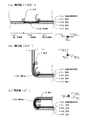
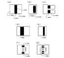
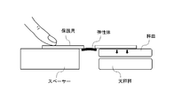
- FIG. 2 is a cross-sectional view of the bent portion 103 portion of the protective device 100
- FIG. 2C is a closed state in which the first flat plate portion 101 and the second flat plate portion 102 are in contact with the protection target so as to sandwich the protection target, respectively.
- closed state (0 °). B
- open state in which the first flat plate portion 101 is rotated 90 ° from the closed state (0 °).
- 90 may be abbreviated as “(90 °)”.
- A) is an open state (hereinafter referred to as “open state (180 °)”) in which the first flat plate portion 101 is rotated 180 ° from the closed state (0 °).
- the bent portion 103 includes an elastic body 105 (silicone rubber) having a circular arc cross section, and one end of the elastic body 105 is a plastic (polypropylene (PP)) core material 106 constituting the first flat plate portion. The other end is fixed to the PP core material 106 that constitutes the second flat plate portion by using an adhesive for hardly adhesive.
- the elastic body 105 is covered with a surface material 107 made of leather that is flexible on both sides, and cannot be seen from the outside.
- the elastic body 105 is obtained by cutting a silicone rubber tube in the extending direction so that the cross section has an arc shape, and a state in which the arc is closed has no distortion.
- the elastic body 105 is distorted by opening the circular arc, and generates a bending stress and a compressive stress to make it close (0 °). . Even in the closed state (0 °), the elastic body 105 remains strained, and a force pressing the first flat plate portion 101 and the second flat plate portion 102 is applied.
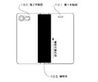
- FIG. 3 is a rear view of the protective device 100 in the open state (180 °), and shows a state in which the surface material 107 on the back surface of the bent portion 103 is peeled off and the elastic body 105 is exposed.
- the elastic body 105 is long in the connecting direction of the first flat plate portion 101 and the second flat plate portion 102 (the length is substantially the same as the long diameter of the first flat plate portion 101 etc.), and Since it is continuously fixed to the core member 106, a force to close the entire plate in the major axis direction of the first flat plate portion 101 and the second flat plate portion 102 is applied (0 °).
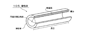
- FIG. 4 is a perspective view showing an example of the shape of the elastic body 105
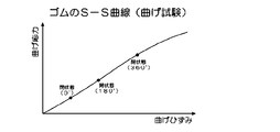
- FIG. 5 is an SS curve of a general rubber bending test.
- the elastic body 105 is intended to be closed (0 °) by strain, bending stress or bending stress and compressive stress in the open state, but in order to rotate the flat plate portion, the weight of the flat plate portion is taken into consideration.
- the physical property (material) and shape of the elastic body are selected.
- the elastic body 105 is easily opened (360 °) by hand force, and reaches the open state (360 °) by elastic deformation (below the elastic limit point) as shown in FIG.
- a stress that can move the first flat plate portion 101 remains even in the closed state (0 °) where the stress is minimized.
- the elastic body 105 has a sufficient cross-sectional area, that is, a length and a thickness so as to obtain an overall force necessary for rotating the entire flat plate portion (see FIG. 4). Therefore, it automatically closes immediately (0 °). For example, when a smartphone is dropped in the open state, it can be closed (0 °) before colliding with the ground to prevent screen breakage. is there.
- the smartphone automatically and quickly closed (0 °) when the reaction force was 10 to 60 g.
- the lower limit of the reaction force is more preferably 20 g or more, still more preferably 25 g or more, and particularly preferably 29 g or more.
- the upper limit of the reaction force is more preferably 50 g or less, still more preferably 45 g or less, and particularly preferably 40 g or less.
- the mass of the first flat plate portion of a general smartphone case is about 10 to 40 g, and the elastic body made of a silicone rubber tube (outer diameter: 8 mm ⁇ inner diameter: 6 mm, length: 140 mm) is the first flat plate. It is clear that sufficient stress can be generated to rotate the part.
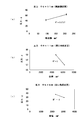
- the reaction force can be adjusted by changing the cross-sectional area or volume of the silicone rubber tube.
- FIG. 11A shows the relationship between the reaction force and the cross-sectional area
- FIGS. 11B and 11C show the relationship between the reaction force and the volume.
- FIG. 11 (a) shows the results of measuring the reaction force of a silicone rubber tube having an inner diameter of 9 mm and an outer diameter of 11 mm, with the cross-sectional area changed by adjusting the length.
- FIG. 11B a silicone rubber tube having an inner diameter of 8 mm, an outer diameter of 11 mm, and a length of 140 mm is used, with a notch and with a quarter of the cylindrical cross section (opening angle is 90 °). This is a result of measuring the reaction force of the object.
- a silicone rubber tube having an inner diameter of 6 mm, an outer diameter of 8 mm, and a length of 140 mm is used, with a notch and with a quarter of the cylindrical cross section (opening angle is 90 °). This is a result of measuring the reaction force of the object. From these results, it can be seen that the reaction force can be adjusted by adjusting the cross-sectional area and volume.
- the shape of the flat plate portion can be appropriately selected according to the protection target.
- the shape of the two flat plate portions does not have to be the same as in the first embodiment (protective device 100).
- the second flat plate portion is the first flat plate as in the protective device of FIG. It may be smaller than the part.
- the mass per flat plate portion is usually 10 to 40 g in the case of a smartphone case, and usually 30 to 200 g in the case of a tablet computer.
- Examples of the material of the flat plate portion or the core material of the flat plate portion include plastic, paper, carbon composite material, metal, etc. Among them, polypropylene (PP) is particularly preferable. Such a material is advantageous in that it is inexpensive and easily available, is lightweight, and is easily bonded to an elastic body.
- PP polypropylene
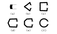
- the bent part connects two flat plate parts in a line, but “connect in a line” means that the parts are connected continuously so as to extend in one direction or two or more points are connected. It means that it is arranged in one direction. Therefore, as in the protective equipment of FIGS. 6A, 6B, 6D, and 6E, the linear direction of the connection is parallel to the major axis direction of the flat plate portion and is continuously connected. However, like the protectors in FIGS. 6C, 6F, and 6G, they are connected at two or more points, and the connection arrangement, that is, the line direction of the connection is parallel to the major axis direction of the flat plate portion. There may be something.
- the bent portion may be capable of rotating the first flat plate portion and / or the second flat plate portion any number of times, but is preferably rotated 360 °.
- the width of the bent portion (the distance between the first flat plate portion 101 and the second flat plate portion 102) can be selected as appropriate according to the protection target or the like. If the object to be protected is thin as shown in FIG. 6 (e), it is bent when nothing is sandwiched between the first flat plate portion 101 and the second flat plate portion 102.
- the necessary minimum width is set in The width of the bent portion is usually 0.1 to 20 mm in the case of a smartphone case, and is usually 0.1 to 25 mm in the case of a tablet computer.
- the material of the elastic body is preferably an elastic body made of resin, and rubber is particularly preferable.
- the elastic body made of resin is inexpensive and easily available, is lightweight, and can be given a function of automatically closing (0 °) with a very simple structure.
- rubber natural rubber; diene rubber such as styrene butadiene rubber (SBR), isoprene rubber (IR), butadiene rubber, chloroprene rubber (CR), nitrile rubber (NBR); silicone rubber, butyl rubber, ethylene propylene rubber, urethane Non-diene rubbers such as rubber and acrylic rubber are exemplified. Of these, silicone rubber is particularly preferable.
- the rubber hardness JIS K 6253, durometer type A
- the rubber hardness is usually 10 to 90, preferably 20 to 80.
- the cross-sectional shape of the elastic body without distortion is the inner surface of the first flat plate portion 101 and the second flat plate portion 102 as shown in FIG.
- Examples of the connecting columnar shape include scissors that sandwich the outer surfaces of the first flat plate portion 101 and the second flat plate portion 102 as shown in FIGS. 7B to 7F.
- the saddle shape includes a polygonal shape such as a triangular shape, a quadrangular shape, a pentagonal shape, and a hexagonal shape (see FIGS. 7B to 7E); an arc shape (see FIG. 7F). .
- a bowl shape is preferable and an arc shape is particularly preferable.
- the thickness when the cross section of the elastic body is bowl-shaped is usually 1 to 10 mm, preferably 5 mm or less.
- the length of the elastic body is usually 50 to 200 mm in the case of a smartphone case, and is usually 100 to 500 mm in the case of a tablet computer.
- the method for adhering the elastic body and the flat plate portion or the core material of the flat plate portion can be appropriately selected according to the material of the elastic body, etc., and examples thereof include adhesives, screws, welding, etc. Among them, the adhesive is preferable. Particularly preferred are adhesives for difficult-to-adhere materials. Such an adhesion method is advantageous in that it is inexpensive, easily available, lightweight, and easy to adhere to an elastic body.
- Protective items to be protected include mobile phones such as smartphones, tablets, computers such as notebook computers, cards such as business cards, books, hand mirrors, and notebooks.
- a mobile phone and a computer having a screen such as a liquid crystal screen are preferable. Since it is such a protection target, it is possible to prevent cracking of the screen and the like, so that the advantages of the protective equipment can be effectively utilized.
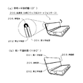
- the protector 200 in FIG. 8 is a smartphone case for protecting a smartphone, and is a split flap type smartphone case in which a flat plate covering a liquid crystal screen is folded in two.
- the flat plate covering the liquid crystal screen has two flat plate portions, that is, a first flat plate portion 201 serving as a front portion of the flap and a second flat plate portion 202 serving as a base portion of the flap (the first flat plate portion 201 and the second flat plate portion). There is a difference in the width of the flat plate portion 202.)
- the flat plate covering the liquid crystal screen has a bent portion 203 that linearly connects the first flat plate portion 201 and the second flat plate portion 202, and the bent portion 203 is configured by an elastic body 205. Therefore, it can deform
- FIG. 8B shows the same plane state in which the first flat plate portion 201 and the second flat plate portion 202 are arranged on the same plane (hereinafter, may be abbreviated as “the same plane state (180 °)”).
- FIG. 8A shows a non-coplanar state in which the first flat plate portion 201 and the second flat plate portion 202 overlap each other (hereinafter referred to as “non-coplanar plane”).
- the circle in FIG. 8A is a cross-sectional view of the bent portion 203 portion in the non-coplanar state (0 °).
- the bent portion 203 includes a flat-plate-shaped elastic body 205 made of silicone rubber, and the elastic body 205 is in an undistorted state when it is in a rectangular parallelepiped shape that is not bent. Accordingly, in the non-coplanar state (0 °), a bending stress is generated to make the same plane state (180 °), the flap is automatically opened, and the first flat plate portion 201 and the second flat plate portion 202 are separated. It will be in the state arranged in the same plane. Therefore, for example, when opening the flat plate covering the liquid crystal screen and operating the screen of the smartphone, by pressing the first flat plate portion 201 and the second flat plate portion 202 by hand to be in a non-coplanar state (0 °), The flat plate covering the liquid crystal screen can be folded small.
- the plane is automatically set to the same plane, and the liquid crystal screen can be protected quickly.
- the flat plate covering the liquid crystal was provided on the back surface even when the flat plate covering the liquid crystal screen was opened to the back of the smartphone (360 ° open state). The camera part can be exposed.
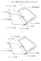
- the protective device 300 in FIG. 9 is a split flap type smartphone case in which a flat plate that covers the liquid crystal screen of the smartphone case of the first embodiment is folded in two.
- the flat plate covering the liquid crystal screen has two flat plates, a first flat plate portion 301 that covers a substantially two-third region below the liquid crystal screen and a second ′ flat plate portion 305 that covers a substantially one-third region above the liquid crystal screen.
- the flat plate covering the liquid crystal screen has a second bent portion 306 that linearly connects the first flat plate portion 301 and the second ′ flat plate portion 305, and the second bent portion 306 is an elastic body 308. It is constituted by.
- the elastic body 308 is made of a silicone rubber formed in a flat plate shape, and is fixed by a core material constituting the first flat plate portion 301 and the second ′ flat plate portion 305 and an adhesive for hardly adhesive. Thereby, it can deform
- FIG. 9A shows the same flat state in which the first flat plate portion 301 and the second ′ flat plate portion 305 are arranged on the same plane
- FIG. 9B shows the second flat plate portion from the same flat state.
- 305 represents a non-coplanar state in which the first flat plate portion 301 and the second ′ flat plate portion 305 overlap each other by rotating 180 °.
- the second 'flat plate portion 305 can be folded by hand to expose the camera portion.
- the screen automatically returns to the same plane state (the state shown in FIG. 9A), and the smartphone screen can be protected.
- the first flat plate portion 301 and the second flat plate portion 302 are connected via a first bent portion constituted by an elastic body 307.
- the elastic body 307 uses a silicone rubber having a substantially arc-shaped cross section by cutting a silicone rubber tube, and a core material constituting the first flat plate portion 301 and the second flat plate portion 302. And is fixed with an adhesive for difficult-to-adhere materials.
- the protective device which is one embodiment of the present invention is a book that covers books, etc., as a cover that protects a computer such as a mobile phone such as a smartphone, a computer such as a tablet computer, a case that stores these, a card case that stores business cards, etc. It can be used as a cover or the like.
- SYMBOLS 100 ... Protective device (smartphone case) 101 ... 1st flat plate part 102 ... 2nd flat plate part 103 ... Bending part 104 ... Protection object holding part, 105 ... Elastic body, 106 ... Core material, 107 ... Surface material DESCRIPTION OF SYMBOLS, S ... Stress, 1 ... 1st flat plate part, 2 ... 2nd flat plate part, 3 ... Bending part, 5 ... Elastic body, 200 ... Protective equipment (divided flap type smart phone case), 201 ... 1st flat plate part, 202 DESCRIPTION OF SYMBOLS ... 2nd flat plate part, 203 ... Bending part, 205 ...
- Elastic body 300 ... Protector (divided flap type smart phone case), 301 ... 1st flat plate part, 302 ... 2nd flat plate part, 303 ... 1st bending part , 304 ... Protection target holding part, 305 ... Second 'flat plate part, 306 ... Second bent part, 307, 308 ... Elastic body
Landscapes
- Engineering & Computer Science (AREA)
- General Engineering & Computer Science (AREA)
- Mechanical Engineering (AREA)
- Theoretical Computer Science (AREA)
- Signal Processing (AREA)
- Human Computer Interaction (AREA)
- Physics & Mathematics (AREA)
- General Physics & Mathematics (AREA)
- Telephone Set Structure (AREA)
- Casings For Electric Apparatus (AREA)
- Purses, Travelling Bags, Baskets, Or Suitcases (AREA)
- Microelectronics & Electronic Packaging (AREA)
Priority Applications (1)
| Application Number | Priority Date | Filing Date | Title |
|---|---|---|---|
| JP2018516220A JP6526914B2 (ja) | 2016-11-21 | 2017-11-21 | 保護具 |
Applications Claiming Priority (8)
| Application Number | Priority Date | Filing Date | Title |
|---|---|---|---|
| JP2016-237988 | 2016-11-21 | ||
| JP2016237988 | 2016-11-21 | ||
| JP2017-008966 | 2017-01-04 | ||
| JP2017008966 | 2017-01-04 | ||
| JP2017025418 | 2017-01-30 | ||
| JP2017-025418 | 2017-01-30 | ||
| JP2017166695 | 2017-08-31 | ||
| JP2017-166695 | 2017-08-31 |
Publications (1)
| Publication Number | Publication Date |
|---|---|
| WO2018092918A1 true WO2018092918A1 (ja) | 2018-05-24 |
Family
ID=62145525
Family Applications (2)
| Application Number | Title | Priority Date | Filing Date |
|---|---|---|---|
| PCT/JP2017/041884 Ceased WO2018092918A1 (ja) | 2016-11-21 | 2017-11-21 | 保護具 |
| PCT/JP2017/041883 Ceased WO2018092917A1 (ja) | 2016-11-21 | 2017-11-21 | ヒンジ |
Family Applications After (1)
| Application Number | Title | Priority Date | Filing Date |
|---|---|---|---|
| PCT/JP2017/041883 Ceased WO2018092917A1 (ja) | 2016-11-21 | 2017-11-21 | ヒンジ |
Country Status (7)
| Country | Link |
|---|---|
| US (1) | US20190110566A1 (enExample) |
| EP (1) | EP3425887A4 (enExample) |
| JP (4) | JP6526914B2 (enExample) |
| KR (1) | KR102103662B1 (enExample) |
| CN (1) | CN108886547A (enExample) |
| HK (1) | HK1256596A1 (enExample) |
| WO (2) | WO2018092918A1 (enExample) |
Cited By (1)
| Publication number | Priority date | Publication date | Assignee | Title |
|---|---|---|---|---|
| JP2020201542A (ja) * | 2019-06-06 | 2020-12-17 | 高橋 茂 | 情報端末機収納ケース |
Families Citing this family (5)
| Publication number | Priority date | Publication date | Assignee | Title |
|---|---|---|---|---|
| KR102645562B1 (ko) * | 2020-02-24 | 2024-03-08 | (주)아모레퍼시픽 | 플립형 어플리케이터 케이스 |
| US12127651B1 (en) * | 2020-07-01 | 2024-10-29 | Apple Inc. | Items with hidden magnets |
| US12139305B2 (en) * | 2020-07-07 | 2024-11-12 | Global Dispensing North America Inc | Extruded spring strap for container and packaging applications |
| US20250066083A1 (en) * | 2021-07-06 | 2025-02-27 | Valentin Leung | Extruded Spring Strap for Container and Packaging Applications |
| WO2025225001A1 (ja) * | 2024-04-26 | 2025-10-30 | Ntt株式会社 | リビングヒンジ部材 |
Citations (2)
| Publication number | Priority date | Publication date | Assignee | Title |
|---|---|---|---|---|
| JP2011119830A (ja) * | 2009-12-01 | 2011-06-16 | Sharp Corp | 折畳み式携帯端末 |
| JP2014141273A (ja) * | 2013-01-23 | 2014-08-07 | Jdp Kk | プラスチックヒンジ及びプラスチック開閉具 |
Family Cites Families (25)
| Publication number | Priority date | Publication date | Assignee | Title |
|---|---|---|---|---|
| JP2992387B2 (ja) * | 1991-12-13 | 1999-12-20 | 株式会社日立製作所 | 電子装置の開閉ヒンジ部構造 |
| GB2342180A (en) * | 1998-09-30 | 2000-04-05 | Optoplast Plc | Spectacles case |
| US6629327B2 (en) * | 2001-05-07 | 2003-10-07 | Thomas F. Adams | Combined cutting and clipping tool for sealed bags |
| US7328480B2 (en) * | 2002-10-10 | 2008-02-12 | International Automotive Components Group North America, Inc. | Coextruded living hinge, a component incorporating the hinge, and methods of making the component |
| US7588166B2 (en) * | 2003-12-10 | 2009-09-15 | Kimberly-Clark Worldwide, Inc. | Dispenser for personal care absorbent articles |
| US20070062964A1 (en) * | 2005-09-20 | 2007-03-22 | Item Source, Llc | Reclosable container with easily openable closure |
| US20070283529A1 (en) * | 2006-06-08 | 2007-12-13 | Nokia Corporation | Plastic living hinge with metal support |
| US20080000671A1 (en) * | 2006-07-03 | 2008-01-03 | Bratt Christopher R | Cable bundle clamp with two opposing spring-loaded hinged shells |
| US7354033B1 (en) * | 2006-08-01 | 2008-04-08 | The United States Of America As Represented By The Secretary Of The Air Force | Tape-spring deployable hinge |
| JP2009225193A (ja) * | 2008-03-17 | 2009-10-01 | Fujitsu Ltd | 携帯端末装置 |
| US9290973B2 (en) * | 2010-09-29 | 2016-03-22 | Plastek Industries, Inc. | Living hinge |
| TWM416304U (en) * | 2011-07-11 | 2011-11-11 | Fu-Yi Hsu | Protective bag |
| JP6102737B2 (ja) * | 2011-08-11 | 2017-03-29 | 日本電気株式会社 | 電子機器の収納ケース |
| JP2014082689A (ja) | 2012-10-17 | 2014-05-08 | Nobuyoshi Masuko | 携帯電子機器の保護カバー |
| CN104640472A (zh) * | 2013-09-13 | 2015-05-20 | 拉塞尔·C·斯坦纳 | 具有整体形成的有回弹力的吊钩的手机外壳 |
| JP2015115999A (ja) * | 2013-12-10 | 2015-06-22 | 矢崎総業株式会社 | 物品 |
| CA2844886C (en) * | 2014-03-06 | 2020-09-01 | Nova Chemicals Corporation | Radiation crosslinked polyethylene hinge |
| KR20170048552A (ko) * | 2014-09-05 | 2017-05-08 | 빅 몬스터 토이즈 엘엘씨 | 흘림 방지 스낵 용기 및 분배기 |
| US9996108B2 (en) * | 2014-09-25 | 2018-06-12 | Dell Products, Lp | Bi-stable hinge |
| WO2016093987A1 (en) * | 2014-12-11 | 2016-06-16 | Dow Global Technologies Llc | Polyethylene compositions having living hinge properties |
| JP6433284B2 (ja) * | 2014-12-22 | 2018-12-05 | 政之 大塚 | スマートフォン用ケース |
| CA2926462A1 (en) * | 2015-04-08 | 2016-10-08 | Gi Sportz Direct Llc | Paintball loader with hinged sidewall |
| WO2017087131A1 (en) * | 2015-11-19 | 2017-05-26 | Dow Global Technologies Llc | Polyethylene compositions having living hinge properties |
| US20180291949A1 (en) * | 2017-04-11 | 2018-10-11 | Dinh Le | Detent Living Hinge |
| US10669762B2 (en) * | 2017-09-20 | 2020-06-02 | Nexus Technologies, Inc. | Hinge |
-
2017
- 2017-11-21 HK HK18115715.2A patent/HK1256596A1/zh unknown
- 2017-11-21 WO PCT/JP2017/041884 patent/WO2018092918A1/ja not_active Ceased
- 2017-11-21 US US16/090,184 patent/US20190110566A1/en not_active Abandoned
- 2017-11-21 EP EP17870676.8A patent/EP3425887A4/en not_active Withdrawn
- 2017-11-21 CN CN201780018958.5A patent/CN108886547A/zh active Pending
- 2017-11-21 JP JP2018516220A patent/JP6526914B2/ja active Active
- 2017-11-21 KR KR1020187028116A patent/KR102103662B1/ko active Active
- 2017-11-21 WO PCT/JP2017/041883 patent/WO2018092917A1/ja not_active Ceased
- 2017-11-21 JP JP2018516218A patent/JP6363319B1/ja active Active
-
2018
- 2018-06-27 JP JP2018121817A patent/JP7098145B2/ja active Active
-
2019
- 2019-05-08 JP JP2019088530A patent/JP2019146262A/ja active Pending
Patent Citations (2)
| Publication number | Priority date | Publication date | Assignee | Title |
|---|---|---|---|---|
| JP2011119830A (ja) * | 2009-12-01 | 2011-06-16 | Sharp Corp | 折畳み式携帯端末 |
| JP2014141273A (ja) * | 2013-01-23 | 2014-08-07 | Jdp Kk | プラスチックヒンジ及びプラスチック開閉具 |
Cited By (1)
| Publication number | Priority date | Publication date | Assignee | Title |
|---|---|---|---|---|
| JP2020201542A (ja) * | 2019-06-06 | 2020-12-17 | 高橋 茂 | 情報端末機収納ケース |
Also Published As
| Publication number | Publication date |
|---|---|
| US20190110566A1 (en) | 2019-04-18 |
| JP7098145B2 (ja) | 2022-07-11 |
| EP3425887A1 (en) | 2019-01-09 |
| WO2018092917A1 (ja) | 2018-05-24 |
| KR20180118185A (ko) | 2018-10-30 |
| JP2019146262A (ja) | 2019-08-29 |
| JPWO2018092917A1 (ja) | 2018-11-15 |
| CN108886547A (zh) | 2018-11-23 |
| JP6526914B2 (ja) | 2019-06-05 |
| JPWO2018092918A1 (ja) | 2018-11-15 |
| JP2019041373A (ja) | 2019-03-14 |
| KR102103662B1 (ko) | 2020-04-22 |
| JP6363319B1 (ja) | 2018-07-25 |
| HK1256596A1 (zh) | 2019-09-27 |
| EP3425887A4 (en) | 2019-03-27 |
Similar Documents
| Publication | Publication Date | Title |
|---|---|---|
| JP2019146262A (ja) | 保護具 | |
| TWI485672B (zh) | 包含帶有壓力分散機構之可撓性顯示器的電子設備 | |
| CN111710247B (zh) | 显示模组及显示装置 | |
| US9846454B2 (en) | Electronic device | |
| US11018710B2 (en) | Accessory device for an electronic device | |
| CN107102692B (zh) | 折叠式显示装置 | |
| US9552018B2 (en) | Electronic apparatus | |
| CN101998786B (zh) | 便携式电子装置 | |
| CN105867546A (zh) | 柔性保护面板、柔性显示屏及移动终端 | |
| US20150253650A1 (en) | Image Capture Device and Clamping Mechanism | |
| US9917266B2 (en) | Bendable device with a window top layer and a body having extendable bending region | |
| JP2017516156A (ja) | 機械的な取付け及び保持構成 | |
| JP5999533B2 (ja) | 携帯電子端末保持具 | |
| CN102207641A (zh) | 显示屏 | |
| TW201544415A (zh) | 保護裝置及其保護罩 | |
| JP6554190B2 (ja) | 視野角変更フィルム及び電子機器 | |
| JP6461632B2 (ja) | タッチパネルの梱包体、保護フィルムおよびタッチパネルの梱包体の製造方法 | |
| JP6338873B2 (ja) | 保護カバーセット | |
| US20100247896A1 (en) | Foam device for use in electronic apparatus | |
| JP2013114016A (ja) | デスプレイパネル斜設用カバーパネル | |
| JP2018026664A (ja) | 携帯情報端末用ケース | |
| JP6465912B2 (ja) | 電子機器用保護カバー | |
| CN102188088A (zh) | 具有支架功能的保护袋 | |
| KR20180125706A (ko) | 접착용 시트 | |
| TW201912966A (zh) | 鉸鏈 |
Legal Events
| Date | Code | Title | Description |
|---|---|---|---|
| ENP | Entry into the national phase |
Ref document number: 2018516220 Country of ref document: JP Kind code of ref document: A |
|
| 121 | Ep: the epo has been informed by wipo that ep was designated in this application |
Ref document number: 17872373 Country of ref document: EP Kind code of ref document: A1 |
|
| NENP | Non-entry into the national phase |
Ref country code: DE |
|
| 122 | Ep: pct application non-entry in european phase |
Ref document number: 17872373 Country of ref document: EP Kind code of ref document: A1 |