WO2018092602A1 - クラッチレリーズ装置 - Google Patents
クラッチレリーズ装置 Download PDFInfo
- Publication number
- WO2018092602A1 WO2018092602A1 PCT/JP2017/039736 JP2017039736W WO2018092602A1 WO 2018092602 A1 WO2018092602 A1 WO 2018092602A1 JP 2017039736 W JP2017039736 W JP 2017039736W WO 2018092602 A1 WO2018092602 A1 WO 2018092602A1
- Authority
- WO
- WIPO (PCT)
- Prior art keywords
- peripheral surface
- inner peripheral
- cylinder
- axial direction
- inclined surface
- Prior art date
- Legal status (The legal status is an assumption and is not a legal conclusion. Google has not performed a legal analysis and makes no representation as to the accuracy of the status listed.)
- Ceased
Links
Images

Classifications
-
- F—MECHANICAL ENGINEERING; LIGHTING; HEATING; WEAPONS; BLASTING
- F16—ENGINEERING ELEMENTS AND UNITS; GENERAL MEASURES FOR PRODUCING AND MAINTAINING EFFECTIVE FUNCTIONING OF MACHINES OR INSTALLATIONS; THERMAL INSULATION IN GENERAL
- F16D—COUPLINGS FOR TRANSMITTING ROTATION; CLUTCHES; BRAKES
- F16D25/00—Fluid-actuated clutches
- F16D25/08—Fluid-actuated clutches with fluid-actuated member not rotating with a clutching member
- F16D25/082—Fluid-actuated clutches with fluid-actuated member not rotating with a clutching member the line of action of the fluid-actuated members co-inciding with the axis of rotation
- F16D25/083—Actuators therefor
Definitions
- Embodiments of the present invention relate to a clutch release device.
- a hydraulic clutch release device in which an oil chamber is formed by an inner housing, an outer housing, and an annular piston, and the annular piston is moved by the oil pressure of the oil chamber.
- the release bearing is moved by the annular piston and the diaphragm spring of the clutch is pushed by the release bearing, the clutch is disengaged.
- the load applied to the housing by the reinforcing sleeve changes.
- the load is weakened, the force with which the reinforcing sleeve supports the housing is weakened, which may reduce the reinforcing effect.
- the load is increased, the housing is deformed, for example, there is a possibility that the sealing performance of the oil chamber is lowered.
- the present invention has been made in view of the above, and provides a clutch release device capable of suppressing a change in reinforcement effect due to variation in product dimensions.
- the clutch release device includes, as an example, a first tube extending in the axial direction, a connection wall extending radially outward from the first tube, and extending in the axial direction from the connection wall.
- a second cylinder, and at least a part of the second cylinder is housed in a chamber provided between the first cylinder and the second cylinder, the piston being movable in the axial direction, and facing the inclined surface
- a first inner peripheral surface and a second inner surface that is aligned in the axial direction with respect to the first inner peripheral surface and faces the inclined surface, and is located on the radially outer side than the first inner peripheral surface.
- a peripheral surface, an end of the first inner peripheral surface in the axial direction, and the second It includes a stepped portion for connecting the ends of the inner circumferential surface, and comprises a reinforcing member in contact with the inclined surface surrounds the second cylinder.
- the reinforcing member can be secondly fixed with a predetermined tightening margin by shifting the position where the stepped portion and the inclined surface contact in the axial direction. It becomes possible to press fit into the inclined surface of the cylinder. Thereby, the load which a reinforcement member acts on a 2nd cylinder can be made constant for every product, and it becomes possible to suppress that a reinforcement effect changes with the dispersion
- the clutch release device further includes, as an example, a limiting member positioned on the radially outer side of the reinforcing member, and the reinforcing member has an end portion facing the connection wall, and a retaining member protruding from the end portion.
- the retainer extends outward in the radial direction, is positioned between the connecting wall and the restricting member in the axial direction, and restricts movement in the axial direction by the connecting wall and the restricting member. Having a nail portion. Therefore, as an example, the reinforcing member is prevented from coming off from the second tube in the axial direction.
- the retaining member has an extending portion that extends in the axial direction from the end portion, and the claw portion extends from the end of the extending portion away from the end portion in the radial direction. It extends outward, and the extension part is separated from the second tube. Therefore, as an example, the occurrence of a load due to the contact between the retaining member and the second cylinder is suppressed, the influence of the reinforcing effect by the reinforcing member is suppressed, and the retaining member is prevented from being deformed. Is done.
- the reinforcing member comes into contact with the inclined surface at least at the end of the second inner peripheral surface away from the step portion in the axial direction and the step portion. Therefore, as an example, the reinforcing member can be easily attached coaxially to the second cylinder, and the desired reinforcing effect by the reinforcing member can be obtained more reliably.
- each of the first inner peripheral surface and the second inner peripheral surface extends in the axial direction. Therefore, as an example, the reinforcing member can be easily manufactured as compared with the case where the first inner peripheral surface and the second inner peripheral surface are inclined with respect to the axial direction.
- the reinforcing member is made of metal and is formed in a cylindrical shape. Therefore, as an example, the load applied by the reinforcing member to the second cylinder can be easily made constant in the circumferential direction.
- the Young's modulus of the reinforcing member is higher than the Young's modulus of the second cylinder. Therefore, as an example, the reinforcing member more easily applies a load to the second cylinder.
- the diameter of the second inner peripheral surface is smaller than the maximum diameter of the inclined surface and larger than the minimum diameter of the inclined surface. Therefore, as an example, the end of the second inner peripheral surface away from the stepped portion in the axial direction can contact the inclined surface, and it is easy to attach the reinforcing member coaxially to the second cylinder, and the reinforcing member is more surely secured. It is possible to obtain a desired reinforcing effect.
- the diameter of the inclined surface at a position where the end of the second inner peripheral surface away from the step portion in the axial direction contacts is smaller than the maximum diameter of the inclined surface. Therefore, as an example, the end of the second inner peripheral surface away from the stepped portion in the axial direction can contact the inclined surface, and it is easy to attach the reinforcing member coaxially to the second cylinder, and the reinforcing member is more surely secured. It is possible to obtain a desired reinforcing effect.
- the end of the second inner peripheral surface away from the step portion in the axial direction and the step portion are recessed into the inclined surface. Therefore, as an example, it is suppressed that a reinforcement member moves with respect to an inclined surface, and it is suppressed that the load which a reinforcement member acts on a 2nd cylinder is changed.
- FIG. 1 is a cross-sectional view illustrating an example of a clutch release device according to one embodiment.
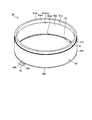
- FIG. 2 is a perspective view illustrating an example of a reinforcing member according to one embodiment.
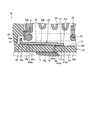
- FIG. 3 is an enlarged cross-sectional view showing a part of an example of the clutch release device of one embodiment.
- FIGS. 1 to 3 a plurality of expressions may be described for the constituent elements according to the embodiment and the description of the elements.
- the constituent elements and descriptions in which a plurality of expressions are made may be other expressions that are not described. Further, the constituent elements and descriptions that are not expressed in a plurality may be expressed in other ways that are not described.
- FIG. 1 is a cross-sectional view showing an example of a clutch release device 10 according to one embodiment.
- the clutch release device 10 in the present embodiment is a hydraulic clutch release device that is operated by hydraulic oil (pressure oil).
- the clutch release device 10 is not limited to this example.
- the clutch release device 10 of the present embodiment is a device that enables hydraulically disconnecting a clutch that transmits and disengages rotational power from the crankshaft of the engine to the input shaft of the transmission.
- the clutch release device 10 includes a cylinder 11, a piston 12, a seal 13, and a release bearing 14.
- An oil chamber 16 is formed by the cylinder 11 and the piston 12.
- the oil chamber 16 is an example of a chamber.
- the clutch release device 10 moves the piston 12 and the release bearing 14 in the axial direction by the hydraulic pressure in the oil chamber 16 to disengage the clutch.
- the clutch release device 10 further includes a first seat member 21, a second seat member 22, a return spring 23, a cover member 24, a retaining ring 25, and a reinforcing member 26.
- the first sheet member 21 is an example of a limiting member.
- the 1st and 2nd sheet members 21 and 22 may also be called a washer, for example.
- the cylinder 11 is made of, for example, a synthetic resin.
- the cylinder 11 may be made of other materials.
- the cylinder 11 includes a first cylinder 31, a second cylinder 32, a flange portion 33, and a plurality of stoppers 34.
- the 1st and 2nd cylinders 31 and 32 may also be called a cylinder wall, a cylinder, or a housing, for example.
- the flange portion 33 is an example of a connection wall.
- the first cylinder 31, the second cylinder 32, and the flange portion 33 are integrally formed.
- the 1st cylinder 31, the 2nd cylinder 32, and the flange part 33 may be formed by a separate component.
- the first cylinder 31 and the second cylinder 32 are formed in a substantially cylindrical shape (annular shape) extending substantially in parallel.
- the first cylinder 31 and the second cylinder 32 are provided substantially coaxially with the crankshaft and the input shaft of the transmission.
- the first cylinder 31, the second cylinder 32, the crankshaft, and the input shaft of the transmission are arranged so as to have a substantially common center axis (rotation center, axis).
- the direction in which the central axis extends (the left-right direction in FIG. 1) is referred to as the axial direction
- the direction rotating around the central axis is referred to as the circumferential direction
- the direction orthogonal to the central axis is referred to as the radial direction. Since the central axis is substantially common, the axial direction, the circumferential direction, and the radial direction in the following description are the axial direction, the circumferential direction, and the radial direction of the clutch release device 10, for example, It is also the axial direction, circumferential direction, and radial direction of the cylinder 31.
- the first cylinder 31 and the second cylinder 32 extend in the axial direction. In the axial direction, the first cylinder 31 is longer than the second cylinder 32.
- the second cylinder 32 surrounds the first cylinder 31 at a position spaced radially outward from the first cylinder 31.
- An oil chamber 16 is provided between the first cylinder 31 and the second cylinder 32.
- an input shaft (rotary shaft) of the transmission is passed inside the first cylinder 31.
- the first cylinder 31 surrounds the input shaft through a gap so that the input shaft can rotate.
- the inner peripheral surface 31a of the first cylinder 31 faces the input shaft.
- the outer peripheral surface 31 b of the first cylinder 31 is located on the opposite side of the inner peripheral surface 31 a and faces the oil chamber 16 and the second cylinder 32.
- the inner peripheral surface 32 a of the second cylinder 32 faces the oil chamber 16 and the first cylinder 31.
- the outer peripheral surface 31 b of the first cylinder 31 and the inner peripheral surface 32 a of the second cylinder 32 define a part of the oil chamber 16.
- the inner peripheral surface 32a of the second cylinder 32 and the inner peripheral surface 31a and the outer peripheral surface 31b of the first cylinder 31 extend substantially parallel to the axial direction.
- the outer peripheral surface 32b of the second cylinder 32 is located on the opposite side of the inner peripheral surface 32a.
- the flange portion 33 is a substantially annular wall that extends radially outward from one end portion 31c of the first tube 31 in the axial direction.
- the first cylinder 31 extends in the axial direction from the flange portion 33.
- the second cylinder 32 also extends from the flange portion 33 in the axial direction. That is, the flange portion 33 connects the first cylinder 31 and the second cylinder 32.
- the outer diameter of the flange portion 33 is larger than the outer diameter of the second tube 32, and the flange portion 33 further extends radially outward from the second tube 32.
- the mounting portion 33 a is provided on the flange portion 33.
- the attachment portion 33a projects outward in the radial direction, and is attached to the transmission housing by, for example, a bolt.
- an oil port is provided in the flange portion 33. The oil port communicates with the oil chamber 16 and, for example, a flow path for supplying the hydraulic oil supplied from the clutch master cylinder to the oil chamber 16 and returning the hydraulic oil in the oil chamber 16 to the clutch master cylinder. It is.
- the stopper 34 is located between the first cylinder 31 and the second cylinder 32 and protrudes from the flange portion 33 in the axial direction.
- the stopper 34 is located in the oil chamber 16.
- the stopper 34 is provided at a position separated from the oil port communicating with the oil chamber 16.
- An inclined surface 37 is provided on the outer peripheral surface 32 b of the second cylinder 32.
- the inclined surface 37 is located on the opposite side of the first cylinder 31.
- the inclined surface 37 is provided over the entire outer peripheral surface 32b.
- the inclined surface 37 may be provided on a part of the outer peripheral surface 32b.
- the inclined surface 37 is a substantially conical surface that spreads radially outward as it approaches the flange portion 33. In other words, the inclined surface 37 tapers as the distance from the flange portion 33 increases. In the present embodiment, the inclined surface 37 has a constant inclination angle, but the inclination angle of the inclined surface 37 may change in the axial direction.
- the piston 12 is formed in a substantially cylindrical shape (annular shape) and is positioned between the first cylinder 31 and the second cylinder 32 in the radial direction. At least a part of the piston 12 is accommodated in the oil chamber 16. The piston 12 is moved in the axial direction by the oil pressure of the oil chamber 16.
- the seal 13 is made of, for example, an elastomer and is formed in a substantially annular shape.
- the seal 13 is attached to one end 12 a of the piston 12 in the axial direction facing the oil chamber 16 and moves integrally with the piston 12.
- the seal 13 seals the oil chamber 16 by being positioned between the first cylinder 31 and the second cylinder 32 in the radial direction.
- the release bearing 14 is a ball bearing attached to the other end 12b of the piston 12 in the axial direction.
- the release bearing 14 includes an inner ring 14a, an outer ring 14b, and a holding member 14c.
- the inner ring 14a rotatably supports the outer ring 14b via a ball.
- the outer ring 14b is always joined to the diaphragm spring of the clutch, and rotates integrally with the diaphragm spring.
- the diaphragm spring presses the clutch disc against the flywheel via the pressure plate.
- the holding member 14c fixes the inner ring 14a to the end 12b of the piston 12 in the axial direction. For this reason, the inner ring 14a and the holding member 14c are stationary without rotating, and the outer ring 14b rotates with respect to the inner ring 14a and the holding member 14c.
- the first sheet member 21 and the second sheet member 22 are made of, for example, metal and are formed in a substantially annular shape.
- the first sheet member 21 and the second sheet member 22 are located on the radially outer side of the second cylinder 32 and surround the first and second cylinders 31 and 32.
- the first sheet member 21 is in contact with the support surface 33b of the flange portion 33.
- the support surface 33b is a surface facing the direction in which the first tube 31 and the second tube 32 extend, and faces the release bearing 14.
- the second seat member 22 is attached to the inner ring 14 a of the release bearing 14.
- the return spring 23 is a coil spring extending in the axial direction.
- the return spring 23 is interposed between the first sheet member 21 and the second sheet member 22 so as to be extendable and contractible.
- the return spring 23 urges the first sheet member 21 toward the flange portion 33 and urges the second sheet member 22 and the release bearing 14 in a direction away from the flange portion 33. For this reason, the return spring 23 presses the release bearing 14 against the diaphragm spring.
- the cover member 24 is a substantially cylindrical bellows.
- the cover member 24 is positioned on the radially outer side than the return spring 23 and covers the return spring 23.
- One end 24a of the cover member 24 is fixed to the first sheet member 21 by, for example, vulcanization adhesion.
- the other end 24b of the cover member 24 is fitted into a recess provided in the second sheet member 22, for example.
- the retaining ring 25 is, for example, a C ring, and is fitted into a groove 31 d provided in the first cylinder 31.
- the groove 31d is provided on the outer peripheral surface 31b in the vicinity of the other end 31e of the first tube 31 in the axial direction, and extends in the circumferential direction.
- the piston 12 is located between the flange portion 33 and the retaining ring 25 in the axial direction.
- the piston 12 contacts the retaining ring 25 when it moves a predetermined distance by the oil pressure of the oil chamber 16. Accordingly, the retaining ring 25 restricts further movement of the piston 12 and suppresses the piston 12 from coming off from the first cylinder 31.
- FIG. 2 is a perspective view showing an example of the reinforcing member 26 of one embodiment.
- the reinforcing member 26 is made of, for example, metal and is formed in a substantially cylindrical shape. For this reason, the Young's modulus of the material of the reinforcing member 26 is higher than the Young's modulus of the material of the cylinder 11.
- the reinforcing member 26 may be made of other materials.
- the reinforcing member 26 includes a small diameter portion 41, a large diameter portion 42, and a plurality of retaining members 43.
- the small diameter portion 41 is formed in a substantially cylindrical shape extending in the axial direction.
- the small diameter portion 41 has a first inner peripheral surface 41a extending in the axial direction. That is, the diameter of the first inner peripheral surface 41a is substantially constant in the axial direction.
- the first inner peripheral surface 41a may be inclined in a substantially conical shape.
- the diameter of the first inner peripheral surface 41 a is smaller than the maximum diameter of the inclined surface 37 of the second cylinder 32 and larger than the minimum diameter of the inclined surface 37.
- the large diameter portion 42 is formed in a substantially cylindrical shape extending in the axial direction, and is arranged substantially coaxially with the small diameter portion 41.
- the large diameter portion 42 has a second inner peripheral surface 42a extending in the axial direction. That is, the diameter of the second inner peripheral surface 42a is substantially constant in the axial direction.
- the second inner peripheral surface 42a may be inclined in a substantially conical shape. The diameter of the second inner peripheral surface 42 a is smaller than the maximum diameter of the inclined surface 37 of the second cylinder 32 and larger than the minimum diameter of the inclined surface 37.
- the first inner peripheral surface 41a and the second inner peripheral surface 42a are part of the inner peripheral surface of the substantially cylindrical reinforcing member 26, respectively. That is, the reinforcing member 26 has a plurality of inner peripheral surfaces 41a and 42a having different inner diameters.
- the first inner peripheral surface 41a and the second inner peripheral surface 42a are arranged substantially coaxially.
- the diameter of the second inner peripheral surface 42a is larger than the diameter of the first inner peripheral surface 41a.
- the 2nd inner peripheral surface 42a is located in the diameter direction outside rather than the 1st inner peripheral surface 41a.
- the small-diameter portion 41 and the large-diameter portion 42 are formed by, for example, pressing one cylindrical material and connected in the axial direction. Therefore, the second inner peripheral surface 42a is aligned in the axial direction with respect to the first inner peripheral surface 41a. In the axial direction, the first inner peripheral surface 41a and the second inner peripheral surface 42a may be adjacent to each other or may be separated from each other.
- the step 45 is provided in the reinforcing member 26 by arranging the first inner peripheral surface 41a and the second inner peripheral surface 42a having different diameters.
- the step portion 45 connects one end 41aa of the first inner peripheral surface 41a in the axial direction and one end 42aa of the second inner peripheral surface 42a.
- the step portion 45 is a portion where the shape between the first inner peripheral surface 41a and the second inner peripheral surface 42a changes.
- the thickness of the small diameter portion 41 and the thickness of the large diameter portion 42 are substantially equal. For this reason, a step is also provided between the outer peripheral surface 41 b of the small diameter portion 41 and the outer peripheral surface 42 b of the large diameter portion 42.
- the reinforcing member 26 may have one outer peripheral surface having a constant diameter.
- the stopper 43 protrudes from one end portion 26a of the reinforcing member 26 in the axial direction.
- An end portion 26 a from which the stopper 43 protrudes is provided in the large diameter portion 42.
- the end portion 26 a is an end portion of the large diameter portion 42 that is away from the small diameter portion 41.
- the retainer 43 has an extending part 43a and a claw part 43b.
- the extending portion 43 a is a substantially rectangular plate-like portion extending in the axial direction from the end portion 26 a of the reinforcing member 26.
- the claw portion 43b extends radially outward from the end of the extending portion 43a that is separated from the end portion 26a. Note that the claw portion 43b may be inclined in the axial direction as long as it extends radially outward.
- FIG. 3 is an enlarged cross-sectional view showing a part of an example of the clutch release device 10 according to one embodiment.
- the stopper 43 is thinner than the small-diameter portion 41 and thinner than the large-diameter portion 42.
- the stopper 43 is positioned on the outer side in the radial direction than the second inner peripheral surface 42 a of the large diameter portion 42.
- the reinforcing member 26 is attached to the inclined surface 37 of the second cylinder 32 by, for example, press fitting.
- the reinforcing member 26 is attached to the second cylinder 32 such that the large diameter portion 42 is closer to the flange portion 33 than the small diameter portion 41 and the end portion 26 a faces the flange portion 33.
- the reinforcing member 26 surrounds the second cylinder 32 and contacts the inclined surface 37. For this reason, the first inner peripheral surface 41 a of the small diameter portion 41 and the second inner peripheral surface 42 a of the large diameter portion 42 face the inclined surface 37.
- the reinforcing member 26 contacts the inclined surface 37 at the other end 42ab of the second inner peripheral surface 42a away from the stepped portion 45 in the axial direction.
- the diameter of the inclined surface 37 at the position where the end 42ab of the second inner peripheral surface 42a contacts is smaller than the maximum diameter of the inclined surface 37.
- the reinforcing member 26 comes into contact with the inclined surface 37 at the step 45 connecting the end 41aa of the first inner peripheral surface 41a and the end 42aa of the second inner peripheral surface 42a.
- the reinforcing member 26 contacts the inclined surface 37 at the end 41aa of the first inner peripheral surface 41a connected to the second inner peripheral surface 42a by the step 45.
- the diameter of the inclined surface 37 at the position where the stepped portion 45 contacts is larger than the minimum diameter of the inclined surface 37.
- the step 45 is assumed to be a virtual conical surface that connects the end 42ab of the second inner peripheral surface 42a and the other end 41ab of the first inner peripheral surface 41a away from the step 45. , And projecting from the surface toward the inclined surface 37 and extending in the circumferential direction. That is, the stepped portion 45 that protrudes toward the inclined surface 37 and contacts the inclined surface 37 has an end 41ab of the first inner peripheral surface 41a and an end 42ab of the second inner peripheral surface 42a that are both ends of the inner peripheral surface. Between.
- the stepped portion 45 is separated from the end 42ab of the second inner peripheral surface 42a in the axial direction.
- the reinforcing member 26 contacts the inclined surface 37 at at least two portions spaced apart in the axial direction.
- the step portion 45 and the end 42ab of the second inner peripheral surface 42a each extend in the circumferential direction.
- the step 45 and the end 42ab of the second inner peripheral surface 42a come into contact with the inclined surface 37, whereby the inclination of the reinforcing member 26 with respect to the second cylinder 32 is corrected, and the reinforcing member 26 and the second cylinder 32 are corrected.
- the end 42 ab and the stepped portion 45 of the second inner peripheral surface 42 a are recessed into the inclined surface 37.
- the first inner peripheral surface 41 a and the second inner peripheral surface 42 a are also in contact with the inclined surface 37.
- the load that the end 42ab of the second inner peripheral surface 42a and the step portion 45 act on the inclined surface 37 is stronger than the load that the first inner peripheral surface 41a and the second inner peripheral surface 42a act on the inclined surface 37. .
- the reinforcing member 26 is press-fitted into the inclined surface 37 so that the amount (tightening allowance) that the reinforcing member 26 sinks into the inclined surface 37 is constant.
- the tightening margin becomes constant by press-fitting the reinforcing member 26 into the inclined surface 37 to a position where a predetermined press-fitting load is obtained.
- the inclination angle of the inclined surface 37 varies from product to product of the cylinder 11 due to variations in product dimensions. For this reason, when press-fitting is performed so that the relative position of the reinforcing member 26 and the inclined surface 37 in the axial direction is constant, the tightening allowance varies and the load that the reinforcing member 26 acts on the second cylinder 32 varies. Sometimes. However, it is possible to make the tightening margin constant by adjusting the relative positions of the reinforcing member 26 and the inclined surface 37 in the axial direction so that a predetermined press-fitting load is obtained. That is, in the present embodiment, there is a degree of freedom in the relative positions of the reinforcing member 26 and the inclined surface 37 in the axial direction.
- a plurality of depressions 47 are provided in the flange portion 33.
- the recess 47 is, for example, a lightening (meat stealing) provided in the cylinder 11 made of synthetic resin, and is a bottomed hole that is recessed from the support surface 33 b of the flange portion 33.
- the stopper 43 is accommodated in the recess 47. For this reason, the nail
- the first sheet member 21 is located on the radially outer side of the reinforcing member 26 and contacts the support surface 33b.
- the first sheet member 21 partially covers the recess 47 and the claw portion 43 b accommodated in the recess 47.
- the claw portion 43 b In the axial direction, the claw portion 43 b is located between the flange portion 33 and the first sheet member 21.
- the claw portion 43 b comes into contact with the bottom of the recess 47 of the flange portion 33.
- the reinforcing member 26 moves in a direction away from the flange portion 33 (right direction in FIG. 1), the claw portion 43 b comes into contact with the first sheet member 21.
- the movement of the claw portion 43b in the axial direction is restricted by the flange portion 33 and the first sheet member 21.
- the second cylinder 32 is pushed radially outward by the hydraulic pressure.
- the reinforcing member 26 reinforces the second cylinder 32 by surrounding and supporting the second cylinder 32 that is to be spread by hydraulic pressure. Thereby, it is suppressed that the volume of the oil chamber 16 expands and the responsiveness of the clutch release apparatus 10 with respect to hydraulic pressure falls.
- the second cylinder 32 that receives a load due to hydraulic pressure tends to cause stress concentration in the vicinity of the flange portion 33.
- the reinforcing member 26 surrounds the second cylinder 32 in the vicinity of the flange portion 33. Thereby, the reinforcing member 26 reinforces the second cylinder 32 in the vicinity of the flange portion 33 and suppresses deformation of the second cylinder 32.
- the reinforcing member 26 that surrounds the second cylinder 32 and contacts the inclined surface 37 includes the first inner peripheral surface 41a and the first inner peripheral surface.
- the step portion 45 has a shape that extends in the circumferential direction and protrudes toward the inclined surface 37 of the second cylinder 32, and contacts the inclined surface 37.
- the reinforcing member 26 can be It becomes possible to press fit into the inclined surface 37 of the second cylinder 32.
- the load which the reinforcement member 26 acts on the 2nd cylinder 32 can be made constant for every product, and it becomes possible to acquire the desired reinforcement effect by the reinforcement member 26 more reliably. That is, it is possible to prevent the reinforcing effect from changing due to variations in product dimensions.
- the deformation of the second cylinder 32 and the oil chamber 16 due to the occurrence of a strong load is suppressed, and the reduction in the reinforcing effect due to the weak load is suppressed.
- the second tube 32 is deformed by the load and heat, so that the stepped portion 45 is fitted into the second tube 32 and the reinforcing member 26 is prevented from coming out of the second tube 32.
- the extending portion 43 a of the stopper 43 is separated from the second cylinder 32. As a result, the generation of a load due to the contact between the retaining member 43 and the second cylinder 32 is suppressed, the influence of the reinforcing effect by the reinforcing member 26 is suppressed, and the retaining member 43 is deformed. It is suppressed.
- the reinforcing member 26 is in contact with the inclined surface 37 at least at the end 42ab of the second inner peripheral surface 42a away from the step 45 in the axial direction and the step 45. Thereby, it becomes easy to attach the reinforcing member 26 to the second cylinder 32 coaxially, and a desired reinforcing effect by the reinforcing member 26 can be obtained more reliably.
- the first inner peripheral surface 41a and the second inner peripheral surface 42a each extend in the axial direction.
- the reinforcement member 26 can be manufactured easily by press work, for example.
Landscapes
- Engineering & Computer Science (AREA)
- General Engineering & Computer Science (AREA)
- Mechanical Engineering (AREA)
- Hydraulic Clutches, Magnetic Clutches, Fluid Clutches, And Fluid Joints (AREA)
- Mechanical Operated Clutches (AREA)
Abstract
本発明のクラッチレリーズ装置(10)は、第1の筒(31)と、第1の筒(31)から径方向外側に広がる接続壁(33)と、接続壁(33)から延び、第1の筒(31)を囲み、第1の筒(31)の反対側に位置するとともに接続壁(33)に近づくに従って径方向外側に広がる傾斜面(37)を有する第2の筒(32)と、第1の筒(31)と第2の筒(32)との間で移動可能なピストン(12)、傾斜面(37)に向く第1の内周面(41a)、第1の内周面(41a)に対して軸方向に並ぶとともに傾斜面(37)に向き、第1の内周面(41a)よりも径方向外側に位置する第2の内周面(42a)、並びに、第1の内周面(41a)の端(41aa)及び第2の内周面(42a)の端(42aa)を接続する段部(45)を有し、且つ第2の筒(32)を囲んで傾斜面(37)に接触する補強部材(26)と、を備える装置である。
Description
本発明の実施形態は、クラッチレリーズ装置に関する。
従来、クラッチレリーズ装置として、内側ハウジング、外側ハウジング、及び環状ピストンによって油室を形成し、当該油室の油圧によって環状ピストンを移動させる油圧式クラッチレリーズ装置が知られる。環状ピストンによりレリーズベアリングが移動させられ、当該レリーズベアリングによってクラッチのダイヤフラムスプリングが押されると、クラッチが遮断状態となる。
内側ハウジング及び外側ハウジングを、合成樹脂を射出成型することにより一体的に形成した油圧式クラッチレリーズ装置も知られる。一般的に合成樹脂は金属よりも強度が低い。このため、合成樹脂によって作られたハウジングは、補強スリーブをスナップにより取り付けられて補強される(特許文献1)。
しかしながら、従来の構成では、ハウジング及び補強スリーブの寸法に製品毎のばらつきが生じると、補強スリーブがハウジングに作用させる荷重が変化する。例えば、当該荷重が弱まると、補強スリーブがハウジングを支持する力が弱まり、補強効果が低下する虞がある。一方、上記荷重が強まると、ハウジングが変形し、例えば油室の密閉性が低下する虞がある。
そこで、本発明は上記に鑑みてなされたものであり、製品の寸法のばらつきによって補強効果が変わることを抑制可能なクラッチレリーズ装置を提供する。
本発明の実施形態に係るクラッチレリーズ装置は、一例として、軸方向に延びる第1の筒と、前記第1の筒から径方向外側に広がる接続壁と、前記接続壁から前記軸方向に延び、前記第1の筒から前記径方向外側に離間した位置で前記第1の筒を囲み、前記第1の筒の反対側に位置するとともに前記接続壁に近づくに従って前記径方向外側に広がる傾斜面を有する、第2の筒と、少なくとも一部が前記第1の筒と前記第2の筒との間に設けられたチャンバに収容され、前記軸方向に移動可能なピストンと、前記傾斜面に向く第1の内周面と、前記第1の内周面に対して前記軸方向に並ぶとともに前記傾斜面に向き、前記第1の内周面よりも前記径方向外側に位置する第2の内周面と、前記軸方向における前記第1の内周面の端及び前記第2の内周面の端を接続する段部と、を有し、前記第2の筒を囲んで前記傾斜面に接触する補強部材と、を備える。よって、一例としては、傾斜面の傾斜角に製品毎のばらつきが生じたとしても、段部と傾斜面とが接触する位置を軸方向にずらすことで、所定の締め代で補強部材を第2の筒の傾斜面に圧入することが可能となる。これにより、補強部材が第2の筒に作用させる荷重を製品毎に一定にすることができ、製品の寸法のばらつきによって補強効果が変わることを抑制することが可能となる。
上記クラッチレリーズ装置は、一例として、前記補強部材の径方向外側に位置する制限部材、をさらに備え、前記補強部材は、前記接続壁に向く端部と、前記端部から突出する抜け止めと、を有し、前記抜け止めは、前記径方向外側に延び、前記軸方向において前記接続壁と前記制限部材との間に位置し、前記接続壁及び前記制限部材によって前記軸方向への移動を制限される、爪部を有する。よって、一例としては、補強部材が第2の筒から軸方向に抜けることが抑制される。
上記クラッチレリーズ装置では、一例として、前記抜け止めは、前記端部から軸方向に延びる延出部を有し、前記爪部は、前記端部から離れた前記延出部の端から前記径方向外側に延び、前記延出部は、前記第2の筒から離間する。よって、一例としては、抜け止めと第2の筒との接触による荷重が発生することが抑制され、補強部材による補強効果に影響が生じることが抑制されるとともに、抜け止めが変形することが抑制される。
上記クラッチレリーズ装置では、一例として、前記補強部材は少なくとも、前記軸方向における前記段部から離れた前記第2の内周面の端と、前記段部と、において前記傾斜面に接触する。よって、一例としては、第2の筒に補強部材を同軸に取り付けることが容易となり、より確実に補強部材による所望の補強効果を得ることが可能となる。
上記クラッチレリーズ装置では、一例として、前記第1の内周面と前記第2の内周面とはそれぞれ、前記軸方向に延びる。よって、一例としては、第1の内周面と第2の内周面とが軸方向に対して傾斜する場合に比べ、補強部材を容易に製造することができる。
上記クラッチレリーズ装置では、一例として、前記補強部材は、金属によって作られ、円筒状に形成される。よって、一例としては、補強部材が第2の筒に作用させる荷重を周方向において一定にしやすくなる。
上記クラッチレリーズ装置では、一例として、前記補強部材のヤング率は、前記第2の筒のヤング率よりも高い。よって、一例としては、補強部材がより第2の筒に荷重を作用させやすくなる。
上記クラッチレリーズ装置では、一例として、前記第2の内周面の直径は、前記傾斜面の最大直径よりも小さく、且つ前記傾斜面の最小直径よりも大きい。よって、一例としては、軸方向における段部から離れた第2の内周面の端が傾斜面に接触でき、第2の筒に補強部材を同軸に取り付けることが容易となり、より確実に補強部材による所望の補強効果を得ることが可能となる。
上記クラッチレリーズ装置では、一例として、前記軸方向における前記段部から離れた前記第2の内周面の端が接触する位置における前記傾斜面の直径は、前記傾斜面の最大直径よりも小さい。よって、一例としては、軸方向における段部から離れた第2の内周面の端が傾斜面に接触でき、第2の筒に補強部材を同軸に取り付けることが容易となり、より確実に補強部材による所望の補強効果を得ることが可能となる。
上記クラッチレリーズ装置では、一例として、前記軸方向における前記段部から離れた前記第2の内周面の端と、前記段部と、が前記傾斜面にめり込む。よって、一例としては、補強部材が傾斜面に対して移動することが抑制され、補強部材が第2の筒に作用させる荷重が変化することが抑制される。
以下に、一つの実施形態について、図1乃至図3を参照して説明する。なお、本明細書において、実施形態に係る構成要素及び当該要素の説明について、複数の表現が記載されることがある。複数の表現がされた構成要素及び説明は、記載されていない他の表現がされても良い。さらに、複数の表現がされない構成要素及び説明も、記載されていない他の表現がされても良い。
図1は、一つの実施形態に係るクラッチレリーズ装置10の一例を示す断面図である。本実施形態におけるクラッチレリーズ装置10は、作動油(圧油)によって動作させられる油圧式クラッチレリーズ装置である。なお、クラッチレリーズ装置10はこの例に限られない。
本実施形態のクラッチレリーズ装置10は、エンジンのクランクシャフトから変速機の入力軸への回転動力を断接可能に伝達するクラッチを、油圧によって遮断可能にする装置である。クラッチレリーズ装置10は、シリンダ11と、ピストン12と、シール13と、レリーズベアリング14とを有する。シリンダ11とピストン12とによって、油室16が形成される。油室16は、チャンバの一例である。クラッチレリーズ装置10は、油室16の油圧によってピストン12及びレリーズベアリング14を軸方向へ移動させ、クラッチを遮断状態にする。
クラッチレリーズ装置10はさらに、第1のシート部材21と、第2のシート部材22と、リターンスプリング23と、カバー部材24と、止め輪25と、補強部材26とを有する。第1のシート部材21は、制限部材の一例である。第1及び第2のシート部材21,22は、例えば、座金とも称され得る。
シリンダ11は、例えば、合成樹脂によって作られる。シリンダ11は、他の材料によって作られても良い。シリンダ11は、第1の筒31と、第2の筒32と、フランジ部33と、複数のストッパ34とを有する。第1及び第2の筒31,32は、例えば、筒壁、シリンダ、又はハウジングとも称され得る。フランジ部33は、接続壁の一例である。第1の筒31、第2の筒32、及びフランジ部33は、一体に形成される。なお、第1の筒31、第2の筒32、及びフランジ部33は、別個の部品により形成されても良い。
第1の筒31及び第2の筒32は、実質的に平行に延びる略円筒状(円環状)に形成される。第1の筒31及び第2の筒32は、クランクシャフト及び変速機の入力軸と略同軸に設けられる。言い換えると、第1の筒31、第2の筒32、クランクシャフト、及び変速機の入力軸は、実質的に共通の中心軸(回転中心、軸心)を持つように配置される。
以下、上記中心軸が延びる方向(図1における左右方向)を軸方向、上記中心軸まわりに回転する方向を周方向、上記中心軸と直交する方向を径方向と称する。なお、中心軸が実質的に共通であるため、以下の説明における軸方向、周方向、及び径方向は、クラッチレリーズ装置10の軸方向、周方向、及び径方向であるとともに、例えば第1の筒31の軸方向、周方向、及び径方向でもある。
第1の筒31及び第2の筒32は、軸方向に延びる。軸方向において、第1の筒31は、第2の筒32よりも長い。第2の筒32は、第1の筒31から径方向外側に離間した位置で第1の筒31を囲む。第1の筒31と第2の筒32との間に、油室16が設けられる。
第1の筒31の内側に、例えば、変速機の入力軸(回転軸)が通される。第1の筒31は、入力軸が回転可能なように、隙間を介して入力軸を囲む。第1の筒31の内周面31aは、入力軸に向く。一方、第1の筒31の外周面31bは、内周面31aの反対側に位置し、油室16及び第2の筒32に向く。
第2の筒32の内周面32aは、油室16及び第1の筒31に向く。第1の筒31の外周面31bと、第2の筒32の内周面32aとは、油室16の一部を規定する。第2の筒32の内周面32aと、第1の筒31の内周面31a及び外周面31bとは、軸方向に略平行に延びる。第2の筒32の外周面32bは、内周面32aの反対側に位置する。
フランジ部33は、軸方向における第1の筒31の一方の端部31cから径方向外側に広がる略円環状の壁である。言い換えると、第1の筒31は、フランジ部33から軸方向に延びる。第2の筒32もまた、フランジ部33から軸方向に延びる。すなわち、フランジ部33は、第1の筒31と第2の筒32とを接続する。フランジ部33の外径は第2の筒32の外径よりも大きく、フランジ部33は第2の筒32からさらに径方向外側に広がる。
フランジ部33に、取付部33aが設けられる。取付部33aは、径方向外側に張り出し、例えばボルトによって変速機のハウジングに取り付けられる。さらに、フランジ部33に油ポートが設けられる。当該油ポートは、油室16に連通され、例えば、クラッチマスタシリンダから供給された作動油を油室16に供給したり、油室16の作動油をクラッチマスタシリンダに戻したりするための流路である。
ストッパ34は、第1の筒31と第2の筒32との間に位置し、フランジ部33から軸方向に突出する。ストッパ34は、油室16に位置する。ストッパ34は、油室16に連通する油ポートから離間した位置に設けられる。
第2の筒32の外周面32bに、傾斜面37が設けられる。言い換えると、傾斜面37は、第1の筒31の反対側に位置する。本実施形態において、傾斜面37は、外周面32bの全域に設けられる。しかし、傾斜面37は、外周面32bの一部に設けられても良い。
傾斜面37は、フランジ部33に近づくに従って径方向外側に広がる、略円錐形状の面である。言い換えると、傾斜面37は、フランジ部33から離れるに従って先細る。本実施形態において、傾斜面37は一定の傾斜角度を有するが、傾斜面37の傾斜角度が軸方向において変化しても良い。
ピストン12は、略筒状(環状)に形成され、径方向において第1の筒31と第2の筒32との間に位置する。ピストン12の少なくとも一部は、油室16に収容される。ピストン12は、油室16の油圧により軸方向に移動させられる。
シール13は、例えばエラストマーにより作られ、略環状に形成される。シール13は、油室16に向く軸方向におけるピストン12の一方の端部12aに取り付けられ、ピストン12と一体的に移動する。シール13は、径方向において第1の筒31と第2の筒32との間に位置することで、油室16を密封する。
レリーズベアリング14は、軸方向におけるピストン12の他方の端部12bに取り付けられたボールベアリングである。レリーズベアリング14は、内輪14aと、外輪14bと、保持部材14cとを有する。
内輪14aは、ボールを介して外輪14bを回動可能に支持する。外輪14bは、クラッチのダイヤフラムスプリングに常時接合され、当該ダイヤフラムスプリングと一体的に回転する。ダイヤフラムスプリングは、プレッシャプレートを介してクラッチディスクをフライホイールに圧接させる。
保持部材14cは、内輪14aを軸方向におけるピストン12の端部12bに固定する。このため、内輪14a及び保持部材14cは回転せず静止しており、外輪14bは内輪14a及び保持部材14cに対して回転する。
第1のシート部材21及び第2のシート部材22は、例えば金属によって作られ、略円環状に形成される。第1のシート部材21及び第2のシート部材22は、第2の筒32の径方向外側に位置して第1及び第2の筒31,32を囲む。
第1のシート部材21は、フランジ部33の支持面33bに接触する。支持面33bは、第1の筒31及び第2の筒32が延びる方向に向く面であり、レリーズベアリング14に向く。第2のシート部材22は、レリーズベアリング14の内輪14aに取り付けられる。
リターンスプリング23は、軸方向に延びるコイルスプリングである。リターンスプリング23は第1のシート部材21と第2のシート部材22との間に伸縮可能に介在する。リターンスプリング23は、第1のシート部材21をフランジ部33に向かって付勢するとともに、第2のシート部材22及びレリーズベアリング14をフランジ部33から離間する方向に付勢する。このため、リターンスプリング23は、レリーズベアリング14をダイヤフラムスプリングに押し付ける。
カバー部材24は、略円筒状のベローズである。カバー部材24は、リターンスプリング23よりも径方向外側に位置し、リターンスプリング23を覆う。カバー部材24の一方の端部24aは、例えば加硫接着により第1のシート部材21に固定される。カバー部材24の他方の端部24bは、例えば第2のシート部材22に設けられた窪みに嵌め込まれる。
止め輪25は、例えばCリングであり、第1の筒31に設けられた溝31dに嵌め込まれる。溝31dは、軸方向における第1の筒31の他方の端部31eの近傍において外周面31bに設けられ、周方向に延びる。
ピストン12は、軸方向において、フランジ部33と止め輪25との間に位置する。ピストン12は、油室16の油圧により所定の距離を移動すると、止め輪25に接触する。これにより、止め輪25は、ピストン12のさらなる移動を制限し、ピストン12が第1の筒31から抜けることを抑制する。
図2は、一つの実施形態の補強部材26の一例を示す斜視図である。補強部材26は、例えば金属によって作られ、略円筒形状に形成される。このため、補強部材26の材料のヤング率は、シリンダ11の材料のヤング率よりも高い。補強部材26は、他の材料によって作られても良い。補強部材26は、小径部41と、大径部42と、複数の抜け止め43とを有する。
小径部41は、軸方向に延びる略円筒形状に形成される。小径部41は、軸方向に延びる第1の内周面41aを有する。すなわち、第1の内周面41aの直径は、軸方向において実質的に一定である。第1の内周面41aは、例えば、略円錐形状に傾斜しても良い。第1の内周面41aの直径は、第2の筒32の傾斜面37の最大直径よりも小さく、傾斜面37の最小直径よりも大きい。
大径部42は、軸方向に延びる略円筒形状に形成され、小径部41と実質的に同軸に配置される。大径部42は、軸方向に延びる第2の内周面42aを有する。すなわち、第2の内周面42aの直径は、軸方向において実質的に一定である。第2の内周面42aは、例えば、略円錐形状に傾斜しても良い。第2の内周面42aの直径は、第2の筒32の傾斜面37の最大直径よりも小さく、傾斜面37の最小直径よりも大きい。
第1の内周面41a及び第2の内周面42aはそれぞれ、略円筒形状の補強部材26の内周面の一部である。すなわち、補強部材26は、内径が異なる複数の内周面41a,42aを有する。
第1の内周面41aと第2の内周面42aとは、実質的に同軸に配置される。第2の内周面42aの直径は、第1の内周面41aの直径よりも大きい。このため、第2の内周面42aは、第1の内周面41aよりも径方向外側に位置する。
小径部41と大径部42とは、例えば一つの円筒形の材料をプレス加工することにより形成され、軸方向に接続される。このため、第2の内周面42aは、第1の内周面41aに対して軸方向に並ぶ。軸方向において、第1の内周面41aと第2の内周面42aとは、隣接していても良いし、互いに離間しても良い。
互いに直径が異なる第1の内周面41aと第2の内周面42aとが並ぶことで、補強部材26に段部45が設けられる。段部45は、軸方向における第1の内周面41aの一方の端41aaと第2の内周面42aの一方の端42aaとを接続する。段部45は、第1の内周面41aと第2の内周面42aとの間の形状が変化する部分である。
小径部41の厚さと、大径部42の厚さとは、実質的に等しい。このため、小径部41の外周面41bと、大径部42の外周面42bとの間にも段が設けられる。なお、補強部材26は、一定の直径を有する一つの外周面を有しても良い。
抜け止め43は、軸方向における補強部材26の一方の端部26aから突出する。抜け止め43が突出する端部26aは、大径部42に設けられる。言い換えると、端部26aは、大径部42の、小径部41から離れた端部である。抜け止め43は、延出部43aと、爪部43bとを有する。
延出部43aは、補強部材26の端部26aから軸方向に延びる略矩形の板状の部分である。爪部43bは、端部26aから離れた延出部43aの端から、径方向外側に延びる。なお、爪部43bは、径方向外側に延びれば、軸方向に傾斜していても良い。
図3は、一つの実施形態のクラッチレリーズ装置10の一例の一部を拡大して示す断面図である。図3に示すように、抜け止め43の厚さは、小径部41の厚さよりも薄く、且つ大径部42の厚さよりも薄い。抜け止め43は、大径部42の第2の内周面42aよりも径方向外側に位置する。
補強部材26は、第2の筒32の傾斜面37に、例えば圧入により取り付けられる。補強部材26は、大径部42が小径部41よりもフランジ部33に近くなり、端部26aがフランジ部33に向くように、第2の筒32に取り付けられる。補強部材26は、第2の筒32を囲んで傾斜面37に接触する。このため、小径部41の第1の内周面41aと、大径部42の第2の内周面42aとは、傾斜面37に向く。
補強部材26は、軸方向における段部45から離れた第2の内周面42aの他方の端42abにおいて、傾斜面37に接触する。第2の内周面42aの端42abが接触する位置における傾斜面37の直径は、傾斜面37の最大直径よりも小さい。
さらに、補強部材26は、第1の内周面41aの端41aaと第2の内周面42aの端42aaとを接続する段部45において、傾斜面37に接触する。別の表現によれば、補強部材26は、段部45によって第2の内周面42aに接続される第1の内周面41aの端41aaにおいて、傾斜面37に接触する。段部45が接触する位置における傾斜面37の直径は、傾斜面37の最小直径よりも大きい。
段部45は、第2の内周面42aの端42abと、段部45から離れた第1の内周面41aの他方の端41abと、をつなぐ仮想的な円錐形状の面を想定した場合、当該面から傾斜面37に向かって突出するとともに周方向に延びる形状を呈する。すなわち、傾斜面37に向かって突出するとともに傾斜面37に接触する段部45が、内周面の両端である第1の内周面41aの端41abと第2の内周面42aの端42abとの間に設けられる。
段部45は、第2の内周面42aの端42abから、軸方向に離間する。このように、補強部材26は、軸方向に離間した少なくとも二つの部分で、傾斜面37に接触する。段部45と、第2の内周面42aの端42abとは、それぞれ周方向に延びる。段部45と、第2の内周面42aの端42abとが傾斜面37に接触することで、第2の筒32に対する補強部材26の傾きが修正され、補強部材26と第2の筒32とが同軸に配置される。
補強部材26が第2の筒32に圧入されることで、第2の内周面42aの端42ab及び段部45は、傾斜面37にめり込む。これにより、第1の内周面41a及び第2の内周面42aも、傾斜面37に接触する。第2の内周面42aの端42ab及び段部45が傾斜面37に作用させる荷重は、第1の内周面41a及び第2の内周面42aが傾斜面37に作用させる荷重よりも強い。
補強部材26は、補強部材26が傾斜面37にめり込む量(締め代)が一定となるように、傾斜面37に圧入される。例えば、所定の圧入荷重となる位置まで補強部材26を傾斜面37に圧入することで、締め代が一定となる。
例えば製品の寸法のばらつきにより、傾斜面37の傾斜角度は、シリンダ11の製品毎にばらつく。このため、軸方向における補強部材26と傾斜面37との相対的な位置が一定となるよう圧入が行われる場合、締め代がばらつき、補強部材26が第2の筒32に作用させる荷重がばらつくことがある。しかし、所定の圧入荷重となるように、軸方向における補強部材26と傾斜面37との相対的な位置を調整することで、締め代を一定にすることが可能となる。すなわち、本実施形態において、軸方向における補強部材26と傾斜面37との相対的な位置には、自由度がある。
フランジ部33に、複数の窪み47が設けられる。窪み47は、例えば、合成樹脂製のシリンダ11に設けられた肉抜き(肉盗み)であり、フランジ部33の支持面33bから窪む有底の穴である。窪み47に、抜け止め43が収容される。このため、抜け止め43の爪部43bは、支持面33bよりもフランジ部33の内側に配置される。
第1のシート部材21は、補強部材26の径方向外側に位置し、支持面33bに接触する。第1のシート部材21は、窪み47と、当該窪み47に収容された爪部43bとを部分的に覆う。
軸方向において、爪部43bは、フランジ部33と第1のシート部材21との間に位置する。補強部材26がフランジ部33に近づく方向(図1の左方向)に移動すると、爪部43bがフランジ部33の窪み47の底に当接する。一方、補強部材26がフランジ部33から離間する方向(図1の右方向)に移動すると、爪部43bが第1のシート部材21に当接する。このように、爪部43bは、フランジ部33及び第1のシート部材21によって軸方向への移動を制限される。
補強部材26が第2の筒32に取り付けられた状態で、抜け止め43の延出部43aは、第2の筒32から離間する。このため、抜け止め43は、第2の筒32の傾斜面37に荷重を作用させない。
例えば、ドライバーがクラッチペダルを踏み込むと、クラッチマスタシリンダから油室16に作動油が供給され、油圧によってピストン12がフランジ部33から離間する方向に移動させられる。ピストン12に取り付けられたレリーズベアリング14がダイヤフラムスプリングを押すことで、クラッチディスクがフライホイールから離間し、クラッチが遮断される。ピストン12が所定の距離を移動すると、止め輪25がピストン12のさらなる移動を制限する。
クラッチペダルが解放されると、油室16の作動油が油ポートから排出され、ピストン12がフランジ部33に近づく方向に移動させられる。これにより、ダイヤフラムスプリングが復帰し、クラッチディスクがフライホイールに圧接されてクラッチが係合する。ピストン12が所定の距離を移動すると、ストッパ34がシール13に当接し、ピストン12のさらなる移動が制限される。このため、ピストン12及びシール13が油ポートを塞ぐことが抑制される。
上述のように、油室16に作動油が供給されるため、油圧によって第2の筒32が径方向外側に押される。補強部材26は、油圧によって広がろうとする第2の筒32を囲んで支持することで、第2の筒32を補強する。これにより、油室16の容積が拡大して油圧に対するクラッチレリーズ装置10の応答性が下がることが抑制される。
油圧による荷重を受ける第2の筒32は、フランジ部33の近傍において応力集中を生じやすい。補強部材26は、フランジ部33の近傍において第2の筒32を囲む。これにより、補強部材26がフランジ部33の近傍において第2の筒32を補強し、第2の筒32の変形を抑制する。
以上説明された一つの実施形態に係るクラッチレリーズ装置10において、第2の筒32を囲んで傾斜面37に接触する補強部材26は、第1の内周面41aと、第1の内周面41aよりも径方向外側に位置する第2の内周面42aと、第1の内周面41aの端41aaと第2の内周面42aの端42aaとを接続する段部45と、を有する。当該補強部材26において、段部45は、周方向に延びるとともに第2の筒32の傾斜面37に向かって突出する形状を呈し、傾斜面37に接触する。このため、傾斜面37の傾斜角に製品毎のばらつきが生じたとしても、段部45と傾斜面37とが接触する位置を軸方向にずらすことで、所定の締め代で補強部材26を第2の筒32の傾斜面37に圧入することが可能となる。これにより、補強部材26が第2の筒32に作用させる荷重を製品毎に一定にすることができ、より確実に補強部材26による所望の補強効果を得ることが可能となる。すなわち、製品の寸法のばらつきによって補強効果が変わることが抑制される。例えば、強い荷重が生じることによる第2の筒32や油室16の変形が抑制されるとともに、荷重が弱いことによる補強効果の低下が抑制される。また、荷重及び熱によって第2の筒32が変形することで、段部45が第2の筒32にめり込み、補強部材26が第2の筒32から抜けることが抑制される。
抜け止め43の爪部43bは、フランジ部33及び第1のシート部材21によって軸方向への移動を制限される。これにより、補強部材26が第2の筒32から軸方向に抜けることが抑制される。
抜け止め43の延出部43aは、第2の筒32から離間する。これにより、抜け止め43と第2の筒32との接触による荷重が発生することが抑制され、補強部材26による補強効果に影響が生じることが抑制されるとともに、抜け止め43が変形することが抑制される。
補強部材26は少なくとも、軸方向における段部45から離れた第2の内周面42aの端42abと、段部45と、において傾斜面37に接触する。これにより、第2の筒32に補強部材26を同軸に取り付けることが容易となり、より確実に補強部材26による所望の補強効果を得ることが可能となる。
第1の内周面41aと第2の内周面42aとはそれぞれ、軸方向に延びる。これにより、第1の内周面41aと第2の内周面42aとが軸方向に対して傾斜する場合に比べ、例えばプレス加工により、補強部材26を容易に製造することができる。
以上、本発明の実施形態を例示したが、上記実施形態および変形例はあくまで一例であって、発明の範囲を限定することは意図していない。上記実施形態や変形例は、その他の様々な形態で実施されることが可能であり、発明の要旨を逸脱しない範囲で、種々の省略、置き換え、組み合わせ、変更を行うことができる。また、各実施形態や各変形例の構成や形状は、部分的に入れ替えて実施することも可能である。
Claims (10)
- 軸方向に延びる第1の筒と、
前記第1の筒から径方向外側に広がる接続壁と、
前記接続壁から前記軸方向に延び、前記第1の筒から前記径方向外側に離間した位置で前記第1の筒を囲み、前記第1の筒の反対側に位置するとともに前記接続壁に近づくに従って前記径方向外側に広がる傾斜面を有する、第2の筒と、
少なくとも一部が前記第1の筒と前記第2の筒との間に設けられたチャンバに収容され、前記軸方向に移動可能なピストンと、
前記傾斜面に向く第1の内周面と、前記第1の内周面に対して前記軸方向に並ぶとともに前記傾斜面に向き、前記第1の内周面よりも前記径方向外側に位置する第2の内周面と、前記軸方向における前記第1の内周面の端及び前記第2の内周面の端を接続する段部と、を有し、前記第2の筒を囲んで前記傾斜面に接触する補強部材と、
を具備するクラッチレリーズ装置。 - 前記補強部材の径方向外側に位置する制限部材、をさらに具備し、
前記補強部材は、前記接続壁に向く端部と、前記端部から突出する抜け止めと、を有し、
前記抜け止めは、前記径方向外側に延び、前記軸方向において前記接続壁と前記制限部材との間に位置し、前記接続壁及び前記制限部材によって前記軸方向への移動を制限される、爪部を有する、
請求項1のクラッチレリーズ装置。 - 前記抜け止めは、前記端部から軸方向に延びる延出部を有し、
前記爪部は、前記端部から離れた前記延出部の端から前記径方向外側に延び、
前記延出部は、前記第2の筒から離間する、
請求項2のクラッチレリーズ装置。 - 前記補強部材は少なくとも、前記軸方向における前記段部から離れた前記第2の内周面の端と、前記段部と、において前記傾斜面に接触する、請求項1のクラッチレリーズ装置。
- 前記第1の内周面と前記第2の内周面とはそれぞれ、前記軸方向に延びる、請求項1乃至請求項4のいずれか一つのクラッチレリーズ装置。
- 前記補強部材は、金属によって作られ、円筒状に形成される、請求項1乃至請求項5のいずれか一つのクラッチレリーズ装置。
- 前記補強部材のヤング率は、前記第2の筒のヤング率よりも高い、請求項1乃至請求項6のいずれか一つのクラッチレリーズ装置。
- 前記第2の内周面の直径は、前記傾斜面の最大直径よりも小さく、且つ前記傾斜面の最小直径よりも大きい、請求項1乃至請求項7のいずれか一つのクラッチレリーズ装置。
- 前記軸方向における前記段部から離れた前記第2の内周面の端が接触する位置における前記傾斜面の直径は、前記傾斜面の最大直径よりも小さい、請求項1乃至請求項8のいずれか一つのクラッチレリーズ装置。
- 前記軸方向における前記段部から離れた前記第2の内周面の端と、前記段部と、が前記傾斜面にめり込む、請求項1乃至請求項9のいずれか一つのクラッチレリーズ装置。
Priority Applications (1)
| Application Number | Priority Date | Filing Date | Title |
|---|---|---|---|
| DE112017005854.6T DE112017005854B4 (de) | 2016-11-18 | 2017-11-02 | Kupplungsausrückvorrichtung |
Applications Claiming Priority (2)
| Application Number | Priority Date | Filing Date | Title |
|---|---|---|---|
| JP2016225344A JP2018080811A (ja) | 2016-11-18 | 2016-11-18 | クラッチレリーズ装置 |
| JP2016-225344 | 2016-11-18 |
Publications (1)
| Publication Number | Publication Date |
|---|---|
| WO2018092602A1 true WO2018092602A1 (ja) | 2018-05-24 |
Family
ID=62146544
Family Applications (1)
| Application Number | Title | Priority Date | Filing Date |
|---|---|---|---|
| PCT/JP2017/039736 Ceased WO2018092602A1 (ja) | 2016-11-18 | 2017-11-02 | クラッチレリーズ装置 |
Country Status (3)
| Country | Link |
|---|---|
| JP (1) | JP2018080811A (ja) |
| DE (1) | DE112017005854B4 (ja) |
| WO (1) | WO2018092602A1 (ja) |
Citations (6)
| Publication number | Priority date | Publication date | Assignee | Title |
|---|---|---|---|---|
| JPS62196933U (ja) * | 1986-06-06 | 1987-12-15 | ||
| US4995492A (en) * | 1989-10-10 | 1991-02-26 | Federal-Mogul Corporation | Reusable position retaining strap for clutch release mechanism |
| JP2002535579A (ja) * | 1999-01-29 | 2002-10-22 | ヴァレオ | 油圧制御式クラッチレリーズ装置 |
| JP2002372075A (ja) * | 2001-06-18 | 2002-12-26 | Koyo Seiko Co Ltd | クラッチ遮断装置 |
| WO2005090812A1 (ja) * | 2004-03-19 | 2005-09-29 | Aisin Seiki Kabushiki Kaisha | 油圧式クラッチレリーズ装置 |
| JP2013100910A (ja) * | 2013-01-25 | 2013-05-23 | Aisin Seiki Co Ltd | 油圧式クラッチレリーズ装置 |
Family Cites Families (2)
| Publication number | Priority date | Publication date | Assignee | Title |
|---|---|---|---|---|
| DE202011109244U1 (de) * | 2011-12-17 | 2012-01-31 | Fte Automotive Gmbh | Zentralausrücker für eine hydraulische Kupplungsbetätigung |
| DE102013226293A1 (de) * | 2012-12-19 | 2014-06-26 | Schaeffler Technologies Gmbh & Co. Kg | Kolben-Zylinder-Anordnung, insbesondere ein Nehmerzylinder für eine hydraulische Kupplungsbetätigungseinrichtung eines Kraftfahrzeuges |
-
2016
- 2016-11-18 JP JP2016225344A patent/JP2018080811A/ja active Pending
-
2017
- 2017-11-02 DE DE112017005854.6T patent/DE112017005854B4/de not_active Expired - Fee Related
- 2017-11-02 WO PCT/JP2017/039736 patent/WO2018092602A1/ja not_active Ceased
Patent Citations (6)
| Publication number | Priority date | Publication date | Assignee | Title |
|---|---|---|---|---|
| JPS62196933U (ja) * | 1986-06-06 | 1987-12-15 | ||
| US4995492A (en) * | 1989-10-10 | 1991-02-26 | Federal-Mogul Corporation | Reusable position retaining strap for clutch release mechanism |
| JP2002535579A (ja) * | 1999-01-29 | 2002-10-22 | ヴァレオ | 油圧制御式クラッチレリーズ装置 |
| JP2002372075A (ja) * | 2001-06-18 | 2002-12-26 | Koyo Seiko Co Ltd | クラッチ遮断装置 |
| WO2005090812A1 (ja) * | 2004-03-19 | 2005-09-29 | Aisin Seiki Kabushiki Kaisha | 油圧式クラッチレリーズ装置 |
| JP2013100910A (ja) * | 2013-01-25 | 2013-05-23 | Aisin Seiki Co Ltd | 油圧式クラッチレリーズ装置 |
Also Published As
| Publication number | Publication date |
|---|---|
| DE112017005854T5 (de) | 2019-08-08 |
| DE112017005854B4 (de) | 2021-04-22 |
| JP2018080811A (ja) | 2018-05-24 |
Similar Documents
| Publication | Publication Date | Title |
|---|---|---|
| US8127911B2 (en) | Clutch actuation guide sleeve and release bearing assembly for a dual clutch transmission | |
| US8051658B2 (en) | Hydraulic element | |
| JP6400002B2 (ja) | 液圧式のシステムのピストン・シリンダユニット | |
| JP6856636B2 (ja) | 摩擦クラッチを操作する液圧式のレリーズシステム用のスレーブシリンダ | |
| WO2015173922A1 (ja) | 防振支持装置 | |
| CN101479495B (zh) | 可液压操作的离合器分离器 | |
| JP7349232B2 (ja) | 密封装置 | |
| EP2172667B1 (en) | Cup seal | |
| US6360863B1 (en) | Clutches | |
| JP2013532093A (ja) | 液圧ブレーキシステム用シール部材 | |
| JP6896098B2 (ja) | ディスクブレーキおよびピストンブーツ | |
| CN105422706A (zh) | 轴承衬套和振荡阻尼连接结构 | |
| JP2018080811A (ja) | クラッチレリーズ装置 | |
| US9217478B2 (en) | Release mechanism for friction clutch | |
| JP6815749B2 (ja) | 密封装置 | |
| JP5125965B2 (ja) | カップシール結合構造 | |
| JP5549750B2 (ja) | 油圧式クラッチレリーズ装置 | |
| JP5262534B2 (ja) | 油圧式クラッチレリーズ装置 | |
| JP2018080813A (ja) | クラッチレリーズ装置 | |
| US8590686B2 (en) | Pull-type friction clutch with integrated clutch release device | |
| JP4767402B2 (ja) | マスタシリンダ | |
| US20080302618A1 (en) | Hydraulic Coupling For An Actuating System For Actuating A Motor Vehicle Clutch | |
| JP2010084892A (ja) | 皿バネ組付体 | |
| JP5024068B2 (ja) | クラッチレリーズ軸受 | |
| CN108930727B (zh) | 用于液压分离系统的从动缸 |
Legal Events
| Date | Code | Title | Description |
|---|---|---|---|
| 121 | Ep: the epo has been informed by wipo that ep was designated in this application |
Ref document number: 17872658 Country of ref document: EP Kind code of ref document: A1 |
|
| 122 | Ep: pct application non-entry in european phase |
Ref document number: 17872658 Country of ref document: EP Kind code of ref document: A1 |