WO2018092472A1 - 流量制御弁 - Google Patents
流量制御弁 Download PDFInfo
- Publication number
- WO2018092472A1 WO2018092472A1 PCT/JP2017/036916 JP2017036916W WO2018092472A1 WO 2018092472 A1 WO2018092472 A1 WO 2018092472A1 JP 2017036916 W JP2017036916 W JP 2017036916W WO 2018092472 A1 WO2018092472 A1 WO 2018092472A1
- Authority
- WO
- WIPO (PCT)
- Prior art keywords
- valve
- valve body
- seat
- upstream
- downstream
- Prior art date
- Legal status (The legal status is an assumption and is not a legal conclusion. Google has not performed a legal analysis and makes no representation as to the accuracy of the status listed.)
- Ceased
Links
Images




Classifications
-
- F—MECHANICAL ENGINEERING; LIGHTING; HEATING; WEAPONS; BLASTING
- F02—COMBUSTION ENGINES; HOT-GAS OR COMBUSTION-PRODUCT ENGINE PLANTS
- F02M—SUPPLYING COMBUSTION ENGINES IN GENERAL WITH COMBUSTIBLE MIXTURES OR CONSTITUENTS THEREOF
- F02M51/00—Fuel-injection apparatus characterised by being operated electrically
- F02M51/06—Injectors peculiar thereto with means directly operating the valve needle
-
- F—MECHANICAL ENGINEERING; LIGHTING; HEATING; WEAPONS; BLASTING
- F16—ENGINEERING ELEMENTS AND UNITS; GENERAL MEASURES FOR PRODUCING AND MAINTAINING EFFECTIVE FUNCTIONING OF MACHINES OR INSTALLATIONS; THERMAL INSULATION IN GENERAL
- F16K—VALVES; TAPS; COCKS; ACTUATING-FLOATS; DEVICES FOR VENTING OR AERATING
- F16K1/00—Lift valves or globe valves, i.e. cut-off apparatus with closure members having at least a component of their opening and closing motion perpendicular to the closing faces
- F16K1/32—Details
- F16K1/34—Cutting-off parts, e.g. valve members, seats
- F16K1/44—Details of seats or valve members of double-seat valves
-
- F—MECHANICAL ENGINEERING; LIGHTING; HEATING; WEAPONS; BLASTING
- F16—ENGINEERING ELEMENTS AND UNITS; GENERAL MEASURES FOR PRODUCING AND MAINTAINING EFFECTIVE FUNCTIONING OF MACHINES OR INSTALLATIONS; THERMAL INSULATION IN GENERAL
- F16K—VALVES; TAPS; COCKS; ACTUATING-FLOATS; DEVICES FOR VENTING OR AERATING
- F16K31/00—Actuating devices; Operating means; Releasing devices
- F16K31/02—Actuating devices; Operating means; Releasing devices electric; magnetic
- F16K31/06—Actuating devices; Operating means; Releasing devices electric; magnetic using a magnet, e.g. diaphragm valves, cutting off by means of a liquid
Definitions
- the present invention relates to a flow control valve used in an internal combustion engine, which has a piezoelectric element whose length is expanded and contracted by an applied voltage, and which opens and closes the valve body by the expansion and contraction of the entire length of the element.
- the flow control valve of the present invention is particularly suitable for use in a fuel injection valve.
- Patent Document 1 Japanese Patent Laid-Open No. 2002-31010
- the fuel injector of Patent Document 1 when the valve element is pushed by directly transmitting the extension of the piezoelectric element to the valve body by starting energization, the tip of the valve body is separated from the valve seat, thereby forming a fuel flow path. Fuel is injected from here.
- the valve body when energization is completed, the valve body is pulled back by the force of the spring provided in the valve body and comes into contact with the valve seat, the fuel flow path is closed and the fuel injection is terminated.
- the piezoelectric element has a structure that expands when a voltage is applied, and therefore has a structure in which fuel is injected by pushing the valve body.
- the tip of the valve body is generally conical, and the generated spray is an umbrella spray.
- the degree of freedom in spray layout is small.
- An object of the present invention is to provide a flow rate control valve having a drive element whose overall length extends in proportion to the voltage, and capable of ejecting fluid from an injection hole with a simple structure and drive method. There is to do.
- An injection hole for injecting fluid a valve body and a valve seat that cooperate to open and close a fluid passage leading to the injection hole, a drive element that extends by energization to drive the valve body, and the valve body
- a flow control valve comprising a biasing member that biases the drive element in a direction opposite to the direction in which the drive element extends
- An injection hole forming member having an inner surface where an inlet of the injection hole opens opposite to a valve body tip surface formed from an outer periphery of the valve body toward a tip center of the valve body.
- the structure of the flow control valve can be simplified, and fuel can be ejected from the multi-holes with a simple structure and driving method.
- FIG. 2 is an enlarged view of a part A and a part B in FIG. 1, showing a positional relationship between a downstream valve body seat portion 2 a and a downstream valve seat 2 a and a positional relationship between a stationary valve 12 and an upstream valve seat 13. .
- Sectional drawing of the whole fuel-injection valve of 3rd Example is shown. It is a figure which shows the valve closing state of the fuel injection valve of 3rd Example. It is a figure which shows the valve opening state of the fuel injection valve of 3rd Example. It is a figure for demonstrating the piezoelectric element of 3rd Example. It is a figure which shows an example of the fixing method of the cap components of the fuel injection valve of 3rd Example. It is a figure which shows an example of the fixing method of the cap components of the fuel injection valve of 3rd Example.
- the upstream side and the downstream side represent the upstream side and the downstream side in the fuel flow direction.
- the end of the fuel injection valve 100A, 100B, 100C on the side where the injection hole 11 is provided is referred to as a front end (end on the front end), and the end opposite to the front end is the base end (base). It is called an end portion on the end side.
- the distal end is the downstream end, and the proximal end is the upstream end.
- the up-down direction used in description is defined based on FIG.
- This vertical direction is defined for the sake of simplicity of explanation, and is not related to the vertical direction in the mounted state of the fuel injection valves 100A, 100B, 100C.
- the vertical direction coincides with the direction along the central axis 100a of the fuel injection valves 100A, 100B, and 100C and the displacement direction of the valve body 2 (open / close valve direction).
- a valve body seat portion provided on the valve body 2 and a valve seat with which the valve body seat portion comes into contact with each other are provided with respect to the fuel injection valve.
- the valve body seat portion and the valve seat provided on the front end side of the fuel injection valve 100B are respectively connected to the first valve body seat portion (downstream valve body seat portion) and Called the first valve seat (downstream valve seat), the valve body seat portion and the valve seat provided on the base end side of the fuel injection valve 100 are the second valve body seat portion (upstream valve body seat portion) and the second valve seat respectively.
- valve seat upstream valve seat
- first valve body seat portion downstream seat Part
- first valve seat downstream valve seat
- FIG. 1 is a cross-sectional view showing a first example (Example 1) of a flow control valve according to the present invention.
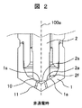
- FIG. 2 is a detailed cross-sectional view of the valve body and the valve seat when the valve is opened.
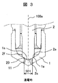
- FIG. 3 is a detailed cross-sectional view of the valve body and the valve seat when the valve is closed. 2 and 3 are enlarged views of a portion A (injection hole sheet portion) in FIG.
- the fuel injection valve 100A shown in FIGS. 1 to 3 is a control valve that is normally opened (when no voltage is applied).
- a valve body sheet portion (first valve body sheet portion, downstream valve body sheet portion) 2a is provided at the distal end portion of the valve body 2, and the downstream valve body sheet portion is formed in the injection hole forming member 1 in which the injection holes are formed.
- a valve seat (first valve seat, downstream valve seat) 1a with which 2a abuts is provided.
- the injection hole forming member 1 is also a valve seat member.
- the valve body 2 and the valve seat 1a cooperate to open and close the fluid passage leading to the injection hole 11.
- the downstream valve seat 1 a and the downstream valve body seat portion 2 a of the valve body 2 constitute an injection hole seat portion (downstream seat portion) 19 that shuts off fuel exhaustion in the vicinity of the injection hole 11.
- the valve body 2 has a radial surface (front end surface) 2s formed at the end portion on the front end side from the radially outer peripheral side toward the front end center (center axis 100a) side, 2s of radial direction surfaces comprise the downstream valve body sheet
- the injection hole forming member 1 is formed in a cap shape that closes the tip of the nozzle 3, and has an inner surface 1s formed to face the radial surface 2s.
- the inner surface 1s constitutes a conical (tapered) valve seat (downstream valve seat) 1a.
- the downstream valve body seat portion 2a of the valve body 2 and the valve seat 1a have an annular contact portion (contact portion) 20 that contacts each other.
- the annular contact portion 20 on the injection hole forming member 1 side may be called a valve seat.
- the diameter of the annular contact portion 20 (hereinafter referred to as a sheet diameter) is SD1.
- the diameter SD1 of the annular contact portion is smaller than the diameter of the end portion on the distal end side of the valve body 2. Further, the annular contact portion 20 exists on the radially outer side than the inlet opening of the injection hole 11.
- Fuel is supplied from the fuel supply port 8 above the fuel injection valve 100 ⁇ / b> A, flows through the gap in the double circular pipe, and from the gap between the nozzle 3 and the outer peripheral surface of the valve body 2, the valve body seat portion 2 a It reaches the contact portion 20 with the valve seat 1a.
- the drive element 6 is an element that expands in proportion to voltage or current.
- the drive element 6 is usually installed at a location isolated from the fuel flow path inside the double circular tube so that fuel is not applied because it is not waterproof.
- the lower end of the drive element 6 is in contact with the proximal end of the valve element 2, and the valve element 2 is directly operated by the extension of the drive element 6. That is, the valve body 2 is displaced in the direction of the on-off valve by the dimension that the drive element 6 extends.
- the driving element 6 extends when energized to drive the valve body 2 in the valve closing direction.
- the valve body 2 is urged in the valve opening direction by the spring 4 and is displaced in the valve opening direction by the urging force of the spring 4 when the drive element 6 is not energized or when the drive voltage or drive current is lowered.
- the driving element 6 can generate a driving force larger than the urging force of the spring 4 to drive the valve body 2 in the valve closing direction. That is, the spring 4 is a biasing member that biases the valve body 2 in a direction opposite to the direction in which the drive element 6 extends.
- the injection hole forming member 1 forming the valve seat 1a is fixed to the tip of the nozzle 3 by a joining method such as welding on the outer periphery.
- Some drive elements 6 have a smaller linear expansion coefficient than the metal parts (for example, stainless steel etc.) which comprise. In this case, when the temperature rises, the constituent metal greatly expands, but the drive element 6 does not extend and the distance to push down the valve body 2 becomes relatively short, and there is a possibility that the fuel cannot be sealed and continue to flow out. is there. Therefore, when the temperature rises, the damper 7 is provided so that there is no gap between the valve seat 1a and the valve body seat portion 2a of the valve body 2.
- the damper 7 includes a cylinder 7a and a plunger 7b, and oil is sealed in a gap between the cylinder 7a and the plunger 7b.
- the oil expands and the cylinder 7a extends. Due to this elongation, there is no gap between the valve seat 1a and the valve body 2.
- FIG. 2 shows the drive state of the valve body 2 when no current is applied (when no voltage is applied).
- the valve body seat portion 2a of the valve body 2 is separated from the valve seat 1a by the biasing force of the spring 4 provided on the valve body 2, and the valve body 2 is in the valve open state. That is, the spring 4 urges the valve body 2 toward the upper side (the base end side of the fuel injection valve 100A) in FIGS.
- a gap is generated between the valve body seat portion 2a and the valve seat 1a, and the seat portion fuel flow path 10 is opened (valve open state).
- the fuel flowing through the fuel flow path 10 passes through the injection hole 11 and is injected to the outside of the fuel injection valve 100A to generate spray.
- FIG. 3 shows the driving state of the valve body 2 when energized (when voltage is applied). Due to the distortion generated by energizing the drive element 6, the drive element 6 extends, and the valve body 2 in contact with the drive element 6 is pushed downward. As a result, the valve seat 1 and the valve body 2 come into contact with each other, and the seat portion fuel flow path 10 is closed (valve closed state), and fuel injection ends.
- the drive element 8 can also be installed in the liquid if it has a waterproof and sealed structure or has fuel resistance.
- the valve body 2 is directly driven by the drive element 6, and is arbitrarily selected from a large number of injection holes 11 provided with inlet openings so as to face the valve body seat portion 2 a provided on the front end surface of the valve body 2. It is possible to form a spray in the direction of Further, the structure of the fuel injection valve 100A can be greatly simplified.
- the fuel injection valve 100A flow rate control valve
- the fuel injection valve 100A flow rate control valve
- the fuel injection valve 100A is configured such that the seat portion fuel flow is brought into contact with the valve seat 1a having one or more injection holes 11 communicating with the surface and opened.
- a valve body 2 that forms a seat portion fuel flow path 10 by closing the passage 10 (fuel passage) and leaving the valve seat 1a.
- a voltage or current is applied to the drive element 6, and when the valve body 2 leaves the valve seat 1a, the voltage applied to the drive element 6 is lowered or the current is stopped.
- the fuel flow path 10 is formed.
- the fuel injection valve 100A (flow rate control valve) of the present embodiment desirably incorporates a drive element 6 whose entire length is displaced in proportion to voltage or current as a drive means of the valve body 2.
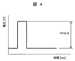
- FIG. 4 is a diagram illustrating a voltage applied to the drive element of the present embodiment.
- a voltage is applied to the drive element 6, the valve seat 1a and the valve body 2 come into contact with each other as shown in FIG. 3, the fuel flow path is closed, and the fuel does not flow out.
- the voltage at this time must be 0 V or more as shown in FIG.
- the drive voltage is set to 0 V or more to protect the drive element 6 from damage.
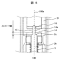
- FIG. 5 is a detailed cross-sectional view showing a modified example of part A in FIG. 1
- the valve body 2 is provided with a small-diameter portion 16 having a small diameter at a part of the upper end portion (end portion on the proximal end side).
- the proximal end of the small diameter portion 16 is in contact with the lower end of the drive element 6.
- the portion in which the small diameter portion 16 is formed is formed at the upper end portion of the portion 2b of the valve body 2 inserted through the inside of the bellows 5, and the valve body portion 2b is a valve in which the valve body seat portion 2a is formed.
- the front end side portion of the body 2 may be formed integrally, or a separate body from the front end side portion of the valve body 2 may be integrally assembled with the front end side portion of the valve body 2.
- the fixed component 14 has a hole portion (a through hole) 14a that slides with the small diameter portion 16 of the valve body 2.
- the lower end surface 15 of the fixed component 14 that opens at the lower end portion of the hole portion 14a, and the valve body
- the valve opening amount (stroke) of the valve body 2 is prescribed
- the driving element 6 Since the driving element 6 has a different amount of elongation depending on the temperature, the driving element 6 is set to have a constant stroke amount between the valve body 2 and the fixed component 14. Thereby, the stroke amount of a valve body becomes fixed, and the dispersion
- the fixed component 14 is formed integrally with the casing 21 that houses the drive element 6, and is provided below the drive element 6 so as to be spaced from the lower end of the drive element 6.
- the fixed component 14 may be a component separate from the casing 21 and may be integrally assembled with the casing 21.
- the fixed component 14 constitutes a stopper that regulates the amount of movement of the valve body 2.
- FIG. 6 is a sectional view showing a second example (Example 2) of the flow control valve according to the present invention.
- FIG. 7 is a detailed cross-sectional view showing a second sheet portion (upstream sheet portion) of the second embodiment.
- the fuel injection valve (fluid control valve) 100B of this embodiment includes the configuration of the fuel injection valve 100A described in the first embodiment, and the configuration described below is the configuration of the fuel injection valve 100A of the first embodiment. Is different.
- the fuel flow is substantially the same as in the first embodiment.
- the part which is different from the configuration of the fuel injection valve 100A of the first embodiment will be described.
- the same reference numerals as those in the first embodiment are given to the same configuration (including substantially the same configuration) as the fuel injection valve 100A of the first embodiment.
- the injection hole seat portion (downstream seat portion) 19 is composed of the downstream valve seat (first valve seat) 1a and the downstream valve seat portion (first valve seat portion) 2a of the valve body 2. Is configured.
- a stationary valve seat portion (upstream seat portion) 23 is provided on the upstream side of the injection hole seat portion 19. The configuration and operation of the injection hole sheet portion 19 are the same as in the first embodiment.
- the stationary valve seat part 23 is comprised by the upstream valve seat (2nd valve seat) 13 and the stationary valve 12 provided in the base end side of the valve body 2 with respect to the downstream valve body sheet
- the upstream valve seat 13 is formed in a casing 17 that surrounds the outer periphery of the valve body 2 and the spring 4, and has a tapered shape.
- the surface of the stationary valve 12 on the side facing the upstream valve seat 13 forms a gentle spherical surface and constitutes the upstream valve body seat portion 12a.
- the upstream valve body seat portion 12a contacts the upstream valve seat 13, whereby the fuel passage formed between the two is closed and the flow of fuel is blocked. Further, when the upstream valve body seat portion 12a is separated from the upstream valve seat 13, a fuel passage formed between the two is opened and fuel flow is allowed.
- the seat surface of the upstream valve seat 13 may be a spherical surface, and the upstream valve body seat portion 12a of the stationary valve 12 may be tapered.
- the spring pressing portion 18 of the spring 4 is provided on the stationary valve 12. That is, the spring pressing portion 18 is configured on the end surface of the stationary valve 12 opposite to the side on which the upstream valve body seat portion 12a is formed, and the spring 4 is in contact with this end surface.
- the stationary valve 12 protrudes in the shape of a bowl from the outer peripheral surface of the valve body 2 toward the radially outer side, and the outer diameter of the stationary valve 12 is larger than the inner diameter of the spring 4. It is larger than the diameter of the shaft portion of the valve body 2 up to the tip of the body 2.
- the stationary valve 12 integrated with the valve body 2 is pushed upward by the urging force of the spring 4, and the upstream valve body seat portion 12a is moved to the upstream valve.
- the fuel flow path is closed by being pressed against the seat 13. That is, the fuel flow in the stationary valve seat portion 23 is blocked.
- the stationary valve seat portion 23 constitutes an upstream seat portion and is located upstream of the injection hole seat portion 19 constituting the downstream seat portion, so that fuel is shut off at the stationary valve seat portion 23. And the fuel outflow from the injection hole sheet
- FIG. 8 is a diagram showing the applied voltage of the drive element.
- FIG. 9 is an enlarged view of A part and B part of FIG. 1, and shows the positional relationship between the downstream valve body seat portion 2 a and the downstream valve seat 2 a and the positional relationship between the stationary valve 12 and the upstream valve seat 13.
- FIG. 9 is an enlarged view of A part and B part of FIG. 1, and shows the positional relationship between the downstream valve body seat portion 2 a and the downstream valve seat 2 a and the positional relationship between the stationary valve 12 and the upstream valve seat 13.
- the downstream valve body seat portion (first valve body seat portion) 2a and the downstream side of the valve body 2 are urged by the urging force of the spring 4 provided on the valve body 2.
- the side valve seat (first valve seat) 1a is in a separated state (opened state) (state (3) in FIG. 9).
- the stationary valve 12 provided in the valve body 2 is in contact with the upstream valve seat 13 (closed state), thereby blocking the fuel.
- the fuel injection valve 100B is formed integrally with or separately from the valve body 2 when application of voltage or current to the drive element 6 such as a piezoelectric element that operates the valve body 2 is stopped.
- a stationary valve 12 that produces the same operation as that of the body 2 abuts on the upstream valve seat 13 and blocks the flow of fuel into the downstream valve seat 1a.
- the valve body 2 always has a structure for closing the fuel flow path, so that there is no fuel leakage when the engine is stopped, and the engine can be stopped safely. That is, when the voltage is not applied (when the engine is stopped), the stationary valve seat portion 23 is closed, thereby blocking the flow of fuel.
- the drive element 6 expands due to distortion generated in the drive element 6.
- the driving force applied to the valve body 2 by the drive element 6 is larger than the urging force of the spring 4, and the valve body 2 is displaced toward the distal end side (downstream valve seat 1a side).
- the downstream valve seat 1a and the downstream valve body seat portion 2a of the valve body 2 are separated from each other (valve open state), and the upstream valve seat 13 and the upstream valve body seat portion of the valve body 2 It will be in the state (valve open state) away from 12a (state of (2) of Drawing 9).
- the fuel that has flowed down the fuel flow path (upstream fuel passage) between the upstream valve seat 13 and the upstream valve body seat portion 12a of the valve body 2 flows into the seat portion fuel flow path (downstream fuel passage) 10. Then, the fuel that has flowed down the seat portion fuel flow path 10 is injected from the injection hole 11 to generate fuel spray.
- the value of the intermediate voltage is lower than the voltage (large voltage or high voltage) at the time of the fuel injection interruption in (1) of FIG.
- a large voltage (high voltage, first voltage) larger than the value of the intermediate voltage is applied to the drive element 6.
- the drive element 6 due to the distortion generated in the drive element 6, the drive element 6 further extends from the state of (2) in FIG. 9, and the valve body 2 is further pushed down (downstream valve seat 1a side).
- the downstream valve body seat portion 2a of the valve body 2 comes into contact with the downstream valve seat 1a (valve closed state), and the seat portion fuel flow path 10 is closed to stop fuel injection.
- the upstream valve body seat portion 12a of the stationary valve 12 is in a state of being separated from the upstream valve seat 13 (valve open state).
- the state (1) and the state (2) in FIG. 9 are repeated, and the fuel injection state and the injection stop state are repeated.
- the voltage applied to the drive element 6 is set to 0 V to return to the state of (3) in FIG. 9, and the stationary valve 12 and the upstream valve seat 13 are connected by the urging force of the spring 4. The fuel flow is prevented from flowing out by closing the fuel flow path.
- the upstream valve body seat portion 12a of the stationary valve 12 and the upstream valve seat 13 have an annular contact portion (contact portion) 22 that contacts each other.
- the annular contact portion 22 on the stationary valve seat portion 13 side may be called a valve seat.
- the diameter of the annular contact portion 22 (hereinafter referred to as the sheet diameter) is SD2.
- the seat diameter SD2 of the annular contact portion 22 is larger than the diameter (seat diameter) SD1 of the annular contact portion 20 between the downstream valve body seat portion 2a and the valve seat 1a.
- the distance dimension between the upstream valve body seat part 12a of the stationary valve 12 and the upstream valve seat 13 is the distance dimension between the downstream valve body sheet part 2a of the valve body 2 and the downstream valve seat 1a.
- the fuel passage cross-sectional area between the upstream valve body seat portion 12a and the upstream valve seat 13 is equal to the fuel passage breakage between the downstream valve body seat portion 2a and the downstream valve seat 1a. It can be larger than the area. For this reason, the fuel can be stably supplied from the upstream side toward the downstream side without increasing the displacement amount of the valve body 2 more than necessary.
- the drive voltage of the drive element 6 is set to 0 V or more, as in the first embodiment.
- the drive element 6 may be a piezoelectric element or an electromagnet using a coil. However, when the drive element 6 is an element that expands when energized, the configuration of this embodiment can be used effectively.
- FIG. 10 shows an overall cross-sectional view of the fuel injection valve of the third embodiment.
- This is a control valve that is normally closed (when no voltage is applied) to the tip of the valve body 2.
- Fuel is supplied from the fuel supply port 8 above the flow rate control valve, flows through the gap between the double circular pipes, and reaches the valve seat from the gap between the nozzle 3 and the valve body 2.
- the driving element 6 is an element that expands in proportion to voltage or current.
- the drive element may be a solenoid such as a coil in which a wire is wound on the circumference. In this case, when the coil is energized, the valve body 2 is pushed down by the magnetic attractive force.
- the tip of the valve element 2 is in contact with the lower end of the drive element 6 and is directly operated by the operation of the drive element 6.
- the valve seat 1a is formed at the outer periphery of the nozzle 3 tip.
- a cap component 1 is provided at the tip of the nozzle 3.
- FIG. 11 is a view showing a closed state of the fuel injection valve of the present embodiment.
- the cap component 1 has one or more first injection holes 11a, and the second injection holes 11b are concentrically opened. In some cases, the second injection hole 11b is not open.
- the second injection hole diameter is set larger than the first injection hole diameter.
- the valve body 2 and the valve seat 1 come into contact with each other by the force of the spring 4 provided on the valve body 2, and the clearance generated thereby closes the seat portion fuel flow path 10 and the injection ends. Since the cap component 1 has the gap 213, if the period from the end of fuel injection to the start becomes longer, the fuel staying in the gap will flow out, so the interval of the injection period (from the start of injection to the start of the next injection)
- the driving condition at a high frequency of 0.5 ms or less is desirable.
- the fuel injection valve of this embodiment includes the valve body 2 that moves in the axial direction, the valve seat 1 that is seated when the valve body 2 moves upstream, and the valve body 2 that is downstream from the valve seat 1. And a fuel passage (seat portion fuel passage 10) formed on the downstream side of the valve seat 1 and on the outer peripheral side of the valve body 2 when moved to. And a plurality of injection holes formed on the downstream side of the fuel passage (seat portion fuel passage 10). It is desirable that the sum of the valve opening time of the valve body 2 and the valve closing time of the valve body 2 in one injection, that is, the interval of the injection period is set to 0.5 m or less.
- valve body 2 is configured to protrude downstream from the tip portion of the nozzle 3, and comes into contact with the seat portion formed at the tip portion of the nozzle 3 when the valve is closed. Further, when the valve body 2 is displaced downstream and is separated from the seat portion 1a when the valve is opened, a fuel passage (seat portion fuel passage 10) is formed, and a plurality of injection holes 11 are formed at the tip portion of the nozzle 3. A hollow cap-shaped component 1 is attached.
- the cap-shaped component 1 is a component that closes the tip of the nozzle 3 and is an injection hole forming member in which an injection hole 11 is formed.
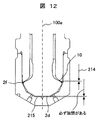
- FIG. 12 is a view showing the opened state of the fuel injection valve of the present embodiment.
- the valve element 2 When the valve element 2 is pushed down so that the stroke amount 214 of the valve element is obtained so that the drive element 6 is energized and a cross-sectional area necessary for the injection flow rate is obtained, the valve element is connected to the inner bottom surface 215 of the cap part. A clearance is always provided at the tip 2d. That is, a gap is formed between the inner diameter side distal end portion of the cap-shaped component 1 and the valve body distal end portion when the valve is opened. Thereby, the deformation of the valve body 2 can be prevented, and the fuel can be stably flowed into the injection hole 11.
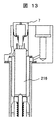
- FIG. 13 is a diagram for explaining the piezoelectric element.
- a piezoelectric element 216 is used as the driving element 6.
- Some members constituting the piezoelectric element 216 have a smaller linear expansion coefficient than metal parts (for example, stainless steel) constituting the flow control valve.
- the damper 7 is provided so that there is no gap between the valve seat 1 and the valve pair when the temperature rises.
- the damper 7 is composed of a cylinder and a plunger, and oil is sealed in the gap between the cylinder and the plunger.
- the piezoelectric element 216 may be installed in a liquid if it has a waterproof and sealed structure or has fuel resistance. Since the piezoelectric element 216 has a very fast operation cycle, it can be driven with a low injection pulse, and can be stably injected with a small flow rate.
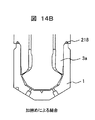
- FIG. 14A and 14B are views showing an example of a method of fixing the cap component of the fuel injection valve of this embodiment.
- the cap component 1 press-fitted into the nozzle 3 is welded 217 (FIG. 14A) or bonded 218 (FIG. 14B) to the nozzle step portion 3a in order to prevent fixation and fuel leakage.
- the fuel pressure is high, the outer periphery of the tip of the nozzle 3 and the inner diameter of the cap part 1 are threaded.
- the end face of the cap part is placed on the wedge, and it is squeezed into the part on the nozzle side so as to be in close contact, and the leakage is prevented by caulking.
- the material is selected so that the cap 1 and the nozzle 3 have a hardness difference. Or you may make it have a hardness difference by heat processing.
- the structure of the flow control valve can be simplified, and the spray is directed in an arbitrary direction.
- An injection hole and a valve body that can be injected can be configured.
- this invention is not limited to each above-mentioned Example, Various modifications are included.
- the above-described embodiments have been described in detail for easy understanding of the present invention, and are not necessarily limited to those having all the configurations.
- a part of the configuration of one embodiment can be replaced with the configuration of another embodiment, and the configuration of another embodiment can be added to the configuration of one embodiment.
- Injection hole forming member (cap parts) 1a Valve seat (first valve seat, downstream valve seat) 2 Valve body 2a Valve body seat portion (first valve body seat portion, downstream valve body seat portion) 3 Nozzle 4 Spring 5 Metallic seal member 6 Drive element 7 Damper 8 Fuel supply port 9 Voltage input terminal 10 Seat part fuel flow path 10A Seat part 11 Injection hole 11a First injection hole 11b Second injection hole 12 Stationary valve 13 Upstream valve seat (second valve seat) 13a Static valve surface 14 Fixing part 15 Hole end face 16 Valve body small diameter part 17 Casing 18 Spring pressing part 19 Injection hole sheet part (downstream sheet part) 23 Static valve seat (upstream seat) 100A, 100B Fuel injection valve 213 Cap component gap 214 Valve body stroke amount 215 Cap component inner bottom surface 216 Piezoelectric element 217 Welded portion 218 Adhesive portion
Landscapes
- Engineering & Computer Science (AREA)
- General Engineering & Computer Science (AREA)
- Mechanical Engineering (AREA)
- Chemical & Material Sciences (AREA)
- Combustion & Propulsion (AREA)
- Fuel-Injection Apparatus (AREA)
- Lift Valve (AREA)
- Electrically Driven Valve-Operating Means (AREA)
- Magnetically Actuated Valves (AREA)
Abstract
本発明の目的は、電圧に比例して全長が伸長する駆動素子を備えた流量制御弁において、簡単な構造、駆動方法にて噴射孔から流体を噴出させることを可能とした流量制御弁を提供することにある。このため、流体を噴射する噴射孔11と、噴射孔11に通じる流体通路の開閉を協働して行う弁体2及び弁座1aと、通電により伸長して弁体2を駆動する駆動素子と、弁体2を駆動素子が伸長する向きとは逆向きに付勢する付勢部材と、を備えた流体噴射弁において、弁体2の外周から弁体の先端中心100aに向かって形成された弁体先端面2sと対向して噴射孔11の入口が開口する内面1sを有する噴射孔形成部材1を備える。
Description
本発明は、内燃機関に用いられる流量制御弁であって、印加電圧により全長が伸縮する圧電素子を有し、前記素子の全長の伸縮により弁体の開閉を行う弁に関する。本発明の流量制御弁は、特に、燃料噴射弁に用いるのに好適である。
本発明の従来技術として、特開2002-31010号公報(特許文献1)に記載された燃料噴射器がある。特許文献1の燃料噴射器は、通電の開始により圧電素子の伸びを直接弁体に伝えて弁体を押すときに、弁体先端部が弁座から離れることにより、燃料流路を形成し、ここから燃料を噴射している。この燃料噴射器は、通電が終了すると弁体に備えられたスプリングの力により、弁体が引き戻されて弁座と当接し、燃料流路が閉鎖して燃料噴射を終了する。
しかしながら、特許文献1の燃料噴射器では、圧電素子は電圧を印加すると伸長する構造であるために、弁体を押すことにより燃料を噴射する構造となる。弁体先端は円錐形状が一般的であり、生成される噴霧は傘状噴霧となる。通電により弁体を引き上げて燃料を多噴孔より噴射する流量制御弁と比較すると、噴霧レイアウトの自由度が少ない。
本発明の目的は、電圧に比例して全長が伸長する駆動素子を備えた流量制御弁において、簡単な構造、駆動方法にて噴射孔から流体を噴出させることを可能とした流量制御弁を提供することにある。
上記目的を達成するために、
流体を噴射する噴射孔と、前記噴射孔に通じる流体通路の開閉を協働して行う弁体及び弁座と、通電により伸長して前記弁体を駆動する駆動素子と、前記弁体を前記駆動素子が伸長する向きとは逆向きに付勢する付勢部材と、を備えた流量制御弁において、
前記弁体の外周から前記弁体の先端中心に向かって形成された弁体先端面と対向して前記噴射孔の入口が開口する内面を有する噴射孔形成部材を備える。
流体を噴射する噴射孔と、前記噴射孔に通じる流体通路の開閉を協働して行う弁体及び弁座と、通電により伸長して前記弁体を駆動する駆動素子と、前記弁体を前記駆動素子が伸長する向きとは逆向きに付勢する付勢部材と、を備えた流量制御弁において、
前記弁体の外周から前記弁体の先端中心に向かって形成された弁体先端面と対向して前記噴射孔の入口が開口する内面を有する噴射孔形成部材を備える。
本発明によれば、流量制御弁の構造を簡略化でき、簡単な構造、駆動方法にて多噴孔から燃料を噴出させることができる。上記した以外の課題、構成及び効果は、以下の実施形態の説明により明らかにされる。
以下に、本発明に係る流量制御弁について、燃料噴射弁を例にとり、その実施例を、図面を参照しながら説明する。なお、以下の説明において、上流側及び下流側は、燃料の流れ方向における上流側及び下流側を表す。また、燃料噴射弁100A、100B,100Cの噴射孔11が設けられる側の端部を先端部(先端側の端部)と呼び、先端部に対して反対側の端部を基端部(基端側の端部)と呼ぶ。先端部は下流側の端部であり、基端部は上流側の端部である。また、説明の中で使用する上下方向を、図1に基づいて定義する。すなわち、基端部は先端部に対して上方にあり、先端部は基端部に対して下方にある。この上下方向は説明を簡便にするために定義するものであり、燃料噴射弁100A、100B,100Cの実装状態における上下方向とは関係が無い。また、上下方向は燃料噴射弁100A、100B,100Cの中心軸線100aに沿う方向及び弁体2の変位方向(開閉弁方向)に一致する。
後述する実施例では、燃料噴射弁に対して、弁体2に設けられる弁体シート部及び弁体シート部が当接する弁座がそれぞれ一つずつ設けられるもの100A,100Cと、弁体2に二つの弁体シート部が設けられ、二つの弁体シート部に対して弁座が一つずつ設けられるもの100Bがある。二つの弁体シート部及び弁座が設けられる実施例において、燃料噴射弁100Bの先端側に設けられる弁体シート部及び弁座をそれぞれ第1弁体シート部(下流側弁体シート部)及び第1弁座(下流側弁座)と呼び、燃料噴射弁100の基端側に設けられる弁体シート部及び弁座をそれぞれ第2弁体シート部(上流側弁体シート部)及び第2弁座(上流側弁座)と呼ぶ。弁体シート部及び弁座がそれぞれ一つずつ設けられる実施例においては、弁体シート部について、また弁座について、特に区別する必要はないが、便宜上、第1弁体シート部(下流側シート部)及び第1弁座(下流側弁座)と呼んで説明する場合がある。
[実施例1] 図1は、本発明に係る流量制御弁の第一実施例(実施例1)を示す断面図である。図2は、開弁時の弁体及び弁座部の詳細断面図である。図3は、閉弁時の弁体及び弁座部の詳細断面図である。なお図2及び図3は、図1のA部(噴射孔シート部)の拡大図である。
図1から図3に示す燃料噴射弁100Aは通常時(電圧未印加時)に開となる制御弁である。弁体2の先端部には弁体シート部(第1弁体シート部、下流側弁体シート部)2aが設けられ、噴射孔が形成された噴射孔形成部材1に下流側弁体シート部2aが当接する弁座(第1弁座、下流側弁座)1aが設けられている。このため、噴射孔形成部材1は弁座部材でもある。弁体2及び弁座1aは、協働して、噴射孔11に通じる流体通路の開閉を行う。下流側弁座1aと弁体2の下流側弁体シート部2aとは、噴射孔11の近傍で燃料の根枯れを遮断する噴射孔シート部(下流側シート部)19を構成する。
すなわち本実施例では、弁体2は、その先端側の端部に、径方向外周側から先端中心(中心軸線100a)側に向かって形成された径方向面(先端面)2sを有し、径方向面2sが下流側弁体シート部2aを構成している。一方、噴射孔形成部材1は、ノズル3の先端部を閉じるキャップ状に形成され、径方向面2sと対向するように形成された内面1sを有する。内面1sは、円錐形状(テーパ状)を成す弁座(下流側弁座)1aを構成する。弁体2の下流側弁体シート部2aと弁座1aとは相互に接触する円環状の接触部(当接部)20を有する。噴射孔形成部材1側の円環状の接触部20を弁座と呼ぶ場合もある。本実施例では、円環状の接触部20の直径(以下、シート径という)はSD1である。円環状の接触部の直径SD1は弁体2の先端側の端部の直径よりも小さい。また円環状の接触部20は、噴射孔11の入口開口よりも径方向外側に存在する。
燃料噴射弁100Aの上方の燃料供給口8から燃料が供給され、二重円管のすきまの流路を流れノズル3と弁体2の外周面との間の隙間から、弁体シート部2aと弁座1aとの接触部20へと到達する。
駆動素子6は電圧又は電流に比例して伸長する素子である。駆動素子6は、通常は防水性を有しないために燃料がかからないように、二重円管の内側の燃料流路と隔離された箇所に設置されている。駆動素子6の下方端部には、弁体2の基端側の端部が当接しており、駆動素子6の伸長により弁体2を直接動作させる。すなわち、弁体2は駆動素子6が伸長した寸法分だけ開閉弁方向に変位する。
本実施例では、駆動素子6は通電時に伸長することによって弁体2を閉弁方向に駆動する。弁体2はスプリング4により開弁方向に付勢されており、駆動素子6の非通電時或いは駆動電圧又は駆動電流を低下させた状態ではスプリング4の付勢力により開弁方向に変位する。駆動素子6は、スプリング4の付勢力よりも大きな駆動力を発生して、弁体2を閉弁方向に駆動することができる。すなわち、スプリング4は弁体2を駆動素子6が伸長する向きとは逆向きに付勢する付勢部材である。
弁座1aを形成する噴射孔形成部材1はノズル3の先端部にたとえば、外周を溶接等の接合方法にて固定されている。駆動素子6には構成している金属部品(例えばステンレス鋼など)より線膨張率が小さいものがある。この場合、温度が上昇すると、構成している金属は大きく伸びるが駆動素子6は伸びずに弁体2を押し下げる距離が相対的に短くなり、燃料のシールが出来ずに流出し続ける可能性がある。そのため、温度が上昇した場合に、弁座1aと弁体2の弁体シート部2aとの間に隙間ができないように、ダンパー7を設ける。
ダンパー7は、シリンダ7aとプランジャ7bとからなり、シリンダ7aとプランジャ7bとの隙間にはオイルが封入されている。温度が高くなるとオイルが膨張し、シリンダ7aが伸びる。この伸びにより、弁座1aと弁体2との隙間が発生しない状態となる。
次に、弁体2の駆動方法いついて説明する。
図2は非通電時(電圧未印加時)における弁体2の駆動状態を示している。電圧未印加時は、弁体2に設けられたスプリング4の付勢力により、弁体2の弁体シート部2aが弁座1aから離れており、弁体2は開弁状態にある。すなわちスプリング4は、弁体2を図1~3上において上側(燃料噴射弁100Aの基端側)に向けて付勢している。これにより弁体シート部2aと弁座1aとの間に隙間が生じ、シート部燃料流路10が開かれた状態(開弁状態)となる。開弁状態において、燃料流路10を流れた燃料は噴射孔11を通過して燃料噴射弁100Aの外部に噴射され、噴霧が生成される。
図2は非通電時(電圧未印加時)における弁体2の駆動状態を示している。電圧未印加時は、弁体2に設けられたスプリング4の付勢力により、弁体2の弁体シート部2aが弁座1aから離れており、弁体2は開弁状態にある。すなわちスプリング4は、弁体2を図1~3上において上側(燃料噴射弁100Aの基端側)に向けて付勢している。これにより弁体シート部2aと弁座1aとの間に隙間が生じ、シート部燃料流路10が開かれた状態(開弁状態)となる。開弁状態において、燃料流路10を流れた燃料は噴射孔11を通過して燃料噴射弁100Aの外部に噴射され、噴霧が生成される。
図3は通電時(電圧印加時)における弁体2の駆動状態を示している。駆動素子6に通電することによって発生する歪みにより、駆動素子6が伸長し、駆動素子6に当接している弁体2が下方に押し下げられる。これにより、弁座1と弁体2とが当接し、シート部燃料流路10を閉塞する状態(閉弁状態)となり、燃料噴射が終了する。なお、駆動素子8は防水密閉構造になっている又は耐燃料性がある場合は、液中に設置することも可能である。本構造では、弁体2を直接駆動素子6にて駆動し、弁体2の先端面に設けられた弁体シート部2aと対向するように入口開口が設けられた多数の噴射孔11から任意の方向に噴霧を形成することが可能である。また、燃料噴射弁100Aの構造を非常に簡略化することが可能である。
すなわち本実施例の燃料噴射弁100A(流量制御弁)は、表面から連通して開口された1つ以上の噴射孔11を有する弁座1aと、弁座1aと当接することによってシート部燃料流路10(燃料通路)を閉じ、弁座1aから離れることによってシート部燃料流路10を形成する弁体2と、を備えている。そして弁体2が弁座1aに当接する場合に、駆動素子6に電圧を印加又は電流を流し、弁体2が弁座1aから離れる場合に駆動素子6への印加電圧を下げる又は電流を停止させて燃料流路10を形成するように構成した。
また本実施例の燃料噴射弁100A(流量制御弁)は、弁体2の駆動手段として電圧又は電流に比例して全長が変位する駆動素子6を内蔵することが望ましい。
図4は、本実施例の駆動素子に印加する電圧を示す図である。
駆動素子6に電圧が印加されている場合、図3に示すように弁座1aと弁体2とが当接し、燃料流路が閉塞されて、燃料は流出しない。このときの電圧は図4に示すように0V以上としなければならない。負の電圧を印加すると、駆動素子6が破損する可能性がある。このため、駆動電圧を0V以上とし、駆動素子6を破損から保護する。
駆動素子6に電圧が印加されている場合、図3に示すように弁座1aと弁体2とが当接し、燃料流路が閉塞されて、燃料は流出しない。このときの電圧は図4に示すように0V以上としなければならない。負の電圧を印加すると、駆動素子6が破損する可能性がある。このため、駆動電圧を0V以上とし、駆動素子6を破損から保護する。
次に、図5を参照して、図1のA部の変更例について説明する。図5は、図1のA部の変更例を示す詳細断面図である。
弁体2は、上端部(基端側の端部)の一部に、径が細くなった小径部16が設けられている。小径部16の基端側の端部は駆動素子6の下端部に当接している。小径部16が形成された部分は、べローズ5の内側に挿通される弁体2の部分2bの上端部に形成されており、この弁体部分2bは弁体シート部2aが形成された弁体2の先端側部分と一体に形成されてもよいし、弁体2の先端側部分とは別体のものが弁体2の先端側部分に一体に組み付けられたものであってもよい。
固定部品14には弁体2の小径部16と摺動する穴部(貫通孔)14aを有しており、この穴部14aの下端部が開口する固定部品14の下端面15と、弁体小径部16と弁体2の先端側の大径部との間の段差面2cとが当接することにより、弁体2の上方(基端側)への移動が規制される。これにより、弁体2の開弁量(ストローク)が規定される。駆動素子6は温度により伸び量が異なるために、弁体2と固定部品14にて一定のストローク量となるよう設定する。これにより、弁体のストローク量が一定となり、流量のばらつきが低減する。
なお固定部品14は、駆動素子6を収容するケーシング21に一体に形成されており、駆動素子6の下方に、駆動素子6の下端部との間に間隔を有するように設けられている。固定部品14は、ケーシング21とは別体の部品で構成され、ケーシング21に一体に組み付けられたものであってもよい。固定部品14は弁体2の移動量を規制するストッパを構成する。
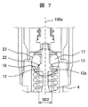
[実施例2] 図6は、本発明に係る流量制御弁の第二実施例(実施例2)を示す断面図である。図7は、第二実施例の第2シート部(上流側シート部)を示す詳細断面図である。
本実施例の燃料噴射弁(流体制御弁)100Bは、第一実施例で説明した燃料噴射弁100Aの構成を備えており、以下で説明する構成が第一実施例の燃料噴射弁100Aの構成と相違している。燃料の流れも第一実施例とほぼ同様である。以下、第一実施例の燃料噴射弁100Aの構成と相違する部分について説明する。また、第一実施例の燃料噴射弁100Aと同様の構成(実質的に同じ構成を含む)には、第一実施例と同じ符号を付して説明する。
本実施例では、下流側弁座(第1弁座)1aと弁体2の下流側弁体シート部(第1弁体シート部)2aとにより、噴射孔シート部(下流側シート部)19が構成される。そして、噴射孔シート部19の上流側に、静止弁シート部(上流側シート部)23が設けられている。噴射孔シート部19の構成及び動作は第一実施例と同様である。
静止弁シート部23は、上流側弁座(第2弁座)13と、下流側弁体シート部2aに対して弁体2の基端側に設けられた静止弁12と、により構成される。上流側弁座13は、弁体2及びスプリング4の外周側を囲むケーシング17に形成され、テーパー状を成している。静止弁12の上流側弁座13と対向する側の表面は、なだらかな球面を成し、上流側弁体シート部12aを構成する。
静止弁シート部23では、上流側弁体シート部12aが上流側弁座13に当接することにより、両者の間に形成される燃料通路が閉じられ、燃料の流れが遮断される。また、上流側弁体シート部12aが上流側弁座13から離間することにより、両者の間に形成される燃料通路が開かれ、燃料の流れが許容される。上流側弁座13のシート面を球面とし、静止弁12の上流側弁体シート部12aをテーパー状にすることも可能である。
また本実施例では、スプリング4のスプリング押さえ部18は静止弁12に設けられている。すなわちスプリング押さえ部18は、静止弁12の上流側弁体シート部12aが形成された側とは反対側の端面に構成され、この端面にスプリング4が当接している。このために、静止弁12は弁体2の外周面から径方向外方に向かって鍔状に突出し、静止弁12の外径はスプリング4の内径よりも大きく、静止弁12の下端部から弁体2の先端部までの間における弁体2の軸部の直径よりも大きい。
機関停止により、電流又は電圧が未印加となると、弁体2と一体となっている静止弁12は、スプリング4の付勢力により上流方向へ押し上げられ、上流側弁体シート部12aが上流側弁座13に押し当てられ、燃料流路が閉塞される。すなわち、静止弁シート部23における燃料流れが遮断される。静止弁シート部23は上流側シート部を構成し、下流側シート部を構成する噴射孔シート部19よりも上流部に構成されているために、静止弁シート部23にて燃料が遮断されると、噴射孔シート部19からの燃料流出は防止される。
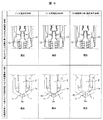
図8は、駆動素子の印加電圧を示す図である。図9は、図1のA部及びB部の拡大図であり、下流側弁体シート部2aと下流側弁座2aとの位置関係及び静止弁12と上流側弁座13との位置関係を示す図である。
本実施例では、電圧未印加時(機関停止時)は、弁体2に設けられたスプリング4の付勢力により弁体2の下流側弁体シート部(第1弁体シート部)2aと下流側弁座(第1弁座)1aとが離れた状態(開弁状態)である(図9の(3)の状態)。この場合、上流側弁座13に弁体2に設けられた静止弁12が当接した状態(閉弁状態)であり、これにより燃料を遮断する。すなわち本実施例では、燃料噴射弁100Bは弁体2を稼働させる圧電素子等の駆動素子6に電圧又は電流の印加が停止した場合、弁体2と一体又は別体として形成され、且つ、弁体2と同一の動作を生じる静止弁12が上流側弁座13に当接し、燃料の下流側弁座1a部への流入を遮断する。これにより、機関の停止時において、弁体2は必ず燃料流路を閉塞する構造であり、機関停止時の燃料洩れがなく、安全に機関を停止することが可能となる。すなわち、電圧未印加時(機関停止時)は、静止弁シート部23が閉弁することにより、燃料の流れが遮断される。
駆動素子6に対する中間電圧(第2電圧)の印加時は、駆動素子6に発生する歪みにより、駆動素子6が伸長する。このときの駆動素子6による弁体2に対する駆動力はスプリング4の付勢力よりも大きく、弁体2を先端側(下流側弁座1a側)に向けて変位させる。これにより下流側弁座1aと弁体2の下流側弁体シート部2aとが離れた状態(開弁状態)になり、且つ、上流側弁座13と弁体2の上流側弁体シート部12aとが離れた状態(開弁状態)になる(図9の(2)の状態)。これにより、上流側弁座13と弁体2の上流側弁体シート部12aとの間の燃料流路(上流側燃料通路)を流下した燃料はシート部燃料流路(下流側燃料通路)10に流れ、シート部燃料流路10を流下した燃料が噴射孔11から噴射され、燃料噴霧が生成される。
この場合の中間電圧の値は、図9の(1)における燃料噴射遮断時の電圧(大電圧又は高電圧)より低く、かつ0V以上とする。
図9の(1)では、中間電圧の値よりも大きな大電圧(高電圧、第1電圧)を駆動素子6に通電する。この場合に駆動素子6に発生する歪みにより、駆動素子6が図9の(2)の状態からさらに伸長して弁体2がさらに下方(下流側弁座1a側)に押し下げられる。その結果、弁体2の下流側弁体シート部2aが下流側弁座1aに当接した状態(閉弁状態)となり、シート部燃料流路10を閉塞して燃料噴射を停止させる。このとき、静止弁12の上流側弁体シート部12aは上流側弁座13から離れた状態(開弁状態)である。
機関が稼働している状態では、図9の(1)の状態と(2)の状態とが繰り返され、燃料の噴射状態と噴射停止状態とが繰り返される。そして、機関が停止した場合は、駆動素子6への印加電圧を0Vとすることで図9の(3)の状態に戻り、スプリング4の付勢力により静止弁12と上流側弁座13とを当接させて燃料流路を閉塞することにより、燃料の流出を防止する。
静止弁12の上流側弁体シート部12aと上流側弁座13とは相互に接触する円環状の接触部(当接部)22を有する。静止弁シート部13側の円環状の接触部22を弁座と呼ぶ場合もある。
本実施例では、円環状の接触部22の直径(以下、シート径という)はSD2である。そして、円環状の接触部22のシート径SD2は、下流側弁体シート部2aと弁座1aとの円環状の接触部20の直径(シート径)SD1よりも大きい。これにより、静止弁12の上流側弁体シート部12aと上流側弁座13との間の間隔寸法が弁体2の下流側弁体シート部2aと下流側弁座1aとの間の間隔寸法と同じである場合に、上流側弁体シート部12aと上流側弁座13との間の燃料通路断面積を、下流側弁体シート部2aと下流側弁座1aとの間の燃料通路断面積よりも大きくすることができる。このため、弁体2の変位量を必要以上に大きくすることなく、上流側から下流側に向けて燃料を安定して供給することができる。
上述したように、本実施例においても、第一実施例と同様に、駆動素子6の駆動電圧は0V以上としている。
駆動素子6は、圧電素子のほか、コイルを用いた電磁石等を用いてもよい。しかし駆動素子6は、通電時に伸長する素子の場合に、本実施例の構成を有効に用いることができる。
[実施例3]
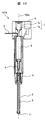
図10は、第三実施例の燃料噴射弁の全体の断面図を示す。
弁体2の先端部に通常時(電圧未印加時)閉とする制御弁である。流量制御弁の上方の燃料供給口8から燃料が供給され、二重円管のすきまの流路を流れノズル3と弁体2のすきまから、弁座部へと到達する。駆動素子6は電圧又は電流に比例して伸長する素子である。なお、この駆動素子は、素線を円周上に巻いたコイル等のソレノイドでもよい。この場合は、コイルに通電したときに、磁気吸引力により弁体2を押し下げる構造とする。駆動素子6の下方端部には、弁体2の先端部が当接しており、駆動素子6の動作によりこれを直接動作させる。弁座1aはノズル3先端外周部に形成されている。ノズル3の先端部にキャップ部品1が設けられている。駆動素子6が動作することにより、当接している弁体2が下方に押し下げられ、弁座1から弁体2が離れ、シート部燃料流路10を形成して、キャップ部品1に開口している噴射孔11より燃料を噴射する。通電が終了すると弁体2に設けられたスプリング4の力により弁体2と弁座1が当接し、これにより生じるすきまがシート部燃料流路10を閉塞し噴射が終了する。すなわち、弁座1及び弁体2は噴射孔11に通じる流体通路の開閉を協働して行う。またスプリング4は、駆動素子6が伸長する向きとは逆向きに、弁体2を付勢する付勢部材である。
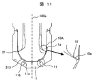
図11は本実施例の燃料噴射弁の閉弁状態を示す図である。
キャップ部品1には1つ以上の第一の噴射孔11aあり、これと同心円状に第二の噴射孔11bが開口している。なお、第二の噴射孔11bが開口していな場合もある。尚、第二の噴射孔径は第一の噴射孔径より大きく設定する。駆動素子6に通電されると、弁体2が押し下げられて、隙間が生じて、シート部10Aに燃料流路が形成される。燃料はシート部10Aより流出してキャップ部品隙間を通り、第一の噴射孔11aを通り、同心円状に第二の噴射孔11bより噴射される。通電が終了すると弁体2に設けられたスプリング4の力により弁体2と弁座1が当接し、これにより生じるすきまがシート部燃料流路10を閉塞し噴射が終了する。キャップ部品1には隙間213を有するために、燃料噴射終了から開始まで期間が長くなると、隙間に滞留している燃料が流出してしまうため、噴射期間の間隔(噴射開始から次の噴射開始までの期間)が0.5ms以下という高周波数での駆動条件が望ましい。
キャップ部品1には1つ以上の第一の噴射孔11aあり、これと同心円状に第二の噴射孔11bが開口している。なお、第二の噴射孔11bが開口していな場合もある。尚、第二の噴射孔径は第一の噴射孔径より大きく設定する。駆動素子6に通電されると、弁体2が押し下げられて、隙間が生じて、シート部10Aに燃料流路が形成される。燃料はシート部10Aより流出してキャップ部品隙間を通り、第一の噴射孔11aを通り、同心円状に第二の噴射孔11bより噴射される。通電が終了すると弁体2に設けられたスプリング4の力により弁体2と弁座1が当接し、これにより生じるすきまがシート部燃料流路10を閉塞し噴射が終了する。キャップ部品1には隙間213を有するために、燃料噴射終了から開始まで期間が長くなると、隙間に滞留している燃料が流出してしまうため、噴射期間の間隔(噴射開始から次の噴射開始までの期間)が0.5ms以下という高周波数での駆動条件が望ましい。
以上のように本実施例の燃料噴射弁は軸方向に移動する弁体2と、弁体2が上流側に移動した場合に着座する弁座1と、弁体2が弁座1から下流側に移動した場合に弁座1の下流側で、かつ、弁体2の外周側に形成される燃料通路(シート部燃料流路10)と、を備える。そしてさらに燃料通路(シート部燃料流路10)の下流側に形成される複数の噴射孔と、を備えた。そして1回の噴射において弁体2の開弁時間と弁体2の閉弁時間の和、すなわち噴射期間の間隔が0.5m以下に設定されたことが望ましい。
また弁体2はノズル3の先端部より下流側に突出するように構成され、閉弁時にノズル3の先端部に形成された前記座部と当接する。また開弁時に弁体2が下流側に変位し、座部1aより離れた場合に燃料通路(シート部燃料流路10)が形成され、ノズル3の先端部に複数の噴射孔11が形成される中空のキャップ状部品1が取り付けられる。キャップ状部品1はノズル3の先端部を閉じる部品であり、噴射孔11が形成された噴射孔形成部材である。
図12は本実施例の燃料噴射弁の開弁状態を示す図である。
駆動素子6に通電され、噴射流量に必要なシート部断面積が得られるような、弁体のストローク量214となるように弁体2が押し下げられた場合、キャップ部品内側底面215にと弁体先端部2dに必ずクリアランスを設ける。つまりキャップ状部品1の内径側先端部と開弁時の弁体先端部との間に隙間が形成される。これにより、弁体2の変形を防ぎ、安定して燃料を噴射孔11に流入させることが可能である。
駆動素子6に通電され、噴射流量に必要なシート部断面積が得られるような、弁体のストローク量214となるように弁体2が押し下げられた場合、キャップ部品内側底面215にと弁体先端部2dに必ずクリアランスを設ける。つまりキャップ状部品1の内径側先端部と開弁時の弁体先端部との間に隙間が形成される。これにより、弁体2の変形を防ぎ、安定して燃料を噴射孔11に流入させることが可能である。
図13は圧電素子を説明するための図である。
駆動素子6に圧電素子216を用いる。流量制御弁を構成している金属部品(例えばステンレス鋼など)より圧電素子216の構成している部材は線膨張率が小さいものがある。このとき、温度が上昇すると、構成している金属は大きく伸びるが駆動素子6は伸びずに弁体2を押し下げる距離が相対的に短くなり、燃料のシールが出来ずに流出し続ける。そのため、温度が上昇した場合は弁座1と弁対隙間ができないようにダンパー7を設ける。ダンパー7にはシリンダとプランジャからなり、シリンダとプランジャの隙間にはオイルが封入されており、温度が高くなるとオイルが膨張し、シリンダが伸びる。この伸びにより、弁座1と弁体2の隙間が発生しない状態となる。なお、圧電素子216は防水密閉構造になっている又は耐燃料性がある場合は液中に設置することも可能である。圧電素子216は動作周期が非常に速いために、低噴射パルスでの駆動が可能であり、小流量で安定して噴射可能となる。
駆動素子6に圧電素子216を用いる。流量制御弁を構成している金属部品(例えばステンレス鋼など)より圧電素子216の構成している部材は線膨張率が小さいものがある。このとき、温度が上昇すると、構成している金属は大きく伸びるが駆動素子6は伸びずに弁体2を押し下げる距離が相対的に短くなり、燃料のシールが出来ずに流出し続ける。そのため、温度が上昇した場合は弁座1と弁対隙間ができないようにダンパー7を設ける。ダンパー7にはシリンダとプランジャからなり、シリンダとプランジャの隙間にはオイルが封入されており、温度が高くなるとオイルが膨張し、シリンダが伸びる。この伸びにより、弁座1と弁体2の隙間が発生しない状態となる。なお、圧電素子216は防水密閉構造になっている又は耐燃料性がある場合は液中に設置することも可能である。圧電素子216は動作周期が非常に速いために、低噴射パルスでの駆動が可能であり、小流量で安定して噴射可能となる。
図14A及び図14Bは本実施例の燃料噴射弁のキャップ部品の固定方法の一例を示す図である。
ノズル3に圧入されたキャップ部品1は、固定と燃料漏れを防止するために、ノズル段差部3aに溶接217(図14A)又は接着218(図14B)を行う。燃料圧力が高い場合は、ノズル3の先端部外周とキャップ部品1の内径にねじ加工を行う。キャップ部品の端面を楔上にして、ノズル側の部品へと食い込ませて密着させて、加締めることにより、燃料の漏れを防ぐ。この場合、キャップ1とノズル3は硬度差を持つように、材料を選定する。又は、熱処理にて硬度差を有するようにしてもよい。また、溶接部217又は接着部218等の固定部は加締めによる固定部に変えてもよい。
ノズル3に圧入されたキャップ部品1は、固定と燃料漏れを防止するために、ノズル段差部3aに溶接217(図14A)又は接着218(図14B)を行う。燃料圧力が高い場合は、ノズル3の先端部外周とキャップ部品1の内径にねじ加工を行う。キャップ部品の端面を楔上にして、ノズル側の部品へと食い込ませて密着させて、加締めることにより、燃料の漏れを防ぐ。この場合、キャップ1とノズル3は硬度差を持つように、材料を選定する。又は、熱処理にて硬度差を有するようにしてもよい。また、溶接部217又は接着部218等の固定部は加締めによる固定部に変えてもよい。
本発明に係る各実施例によれば、電圧に比例して全長が伸長する駆動素子を用いた流量制御弁において、流量制御弁の構造を簡略化でき、噴霧を任意の方向を指向するように噴射することができる噴孔及び弁体を構成することができる。
なお、本発明は上記した各実施例に限定されるものではなく、様々な変形例が含まれる。例えば、上記した実施例は本発明を分かりやすく説明するために詳細に説明したものであり、必ずしも全ての構成を備えるものに限定されるものではない。また、ある実施例の構成の一部を他の実施例の構成に置き換えることが可能であり、また、ある実施例の構成に他の実施例の構成を加えることも可能である。また、各実施例の構成の一部について、他の構成の追加・削除・置換をすることが可能である。
1 噴射孔形成部材(キャップ部品)
1a 弁座(第1弁座、下流側弁座)
2 弁体
2a 弁体シート部(第1弁体シート部、下流側弁体シート部)
3 ノズル
4 スプリング
5 金属性シール部材
6 駆動素子
7 ダンパー
8 燃料供給口
9 電圧入力端子
10 シート部燃料流路
10A シート部
11 噴射孔
11a 第一の噴射孔
11b 第二の噴射孔
12 静止弁
13 上流側弁座(第2弁座)
13a 静止弁表面
14 固定部品
15 穴部端面
16 弁体小径部
17 ケーシング
18 スプリング押さえ部品
19 噴射孔シート部(下流側シート部)
23 静止弁シート部(上流側シート部)
100A,100B 燃料噴射弁
213 キャップ部品隙間
214 弁体のストローク量
215 キャップ部品内側底面
216 圧電素子
217 溶接箇所
218 接着部
Claims (9)
- 流体を噴射する噴射孔と、前記噴射孔に通じる流体通路の開閉を協働して行う弁体及び弁座と、通電により伸長して前記弁体を駆動する駆動素子と、前記弁体を前記駆動素子が伸長する向きとは逆向きに付勢する付勢部材と、を備えた流量制御弁において、
前記弁体の外周から前記弁体の先端中心に向かって形成された弁体先端面と対向して前記噴射孔の入口が開口する内面を有する噴射孔形成部材を備えたことを特徴とする流量制御弁。 - 請求項1に記載の流量制御弁において、
前記弁体は、前記駆動素子への通電が行われていない状態において、前記弁座に当接して前記流体通路を閉じることを特徴とする流量制御弁。 - 請求項2に記載の流量制御弁において、
前記弁座を上流側弁座として前記上流側弁座の下流側に下流側弁座を備え、
前記弁体は、前記上流側弁座に当接する上流側弁体シート部と、前記上流側弁体シート部の下流側に下流側弁体シート部と、を備え、
前記駆動素子に第1電圧を通電した場合に、前記下流側弁体シート部は前記下流側弁座に当接して前記下流側弁体シート部と前記下流側弁座との間に構成される下流側燃料通路を閉じることを特徴とする流量制御弁。 - 請求項3に記載の流量制御弁において、
前記駆動素子に印加する電圧は0V以上とし、
前記駆動素子への通電期間中に、0Vよりも大きく前記第1電圧よりも小さい第2電圧を前記駆動素子に印加することにより、前記下流側燃料通路と、前記上流側弁体シート部と前記上流側弁座との間に構成される上流側燃料通路と、の両方が開いた状態となるように、前記弁体を変位させることを特徴とする流量制御弁。 - 請求項4に記載の流量制御弁において、
前記上流側弁体シート部と前記上流側弁座とは環状の上流側当接部を構成し、
前記下流側弁体シート部と前記下流側弁座とは環状の下流側当接部を構成し、
前記上流側当接部の直径は前記下流側当接部の直径よりも大きいことを特徴とする流量制御弁。 - 請求項5に記載の流量制御弁において、
前記弁体は、前記上流側弁体シート部と前記下流側弁体シート部との間に軸部を備えると共に、前記軸部の上流側端部の外周面から径方向外方に突出した突出部を備え、
前記上流側弁体シート部は前記突出部の上流側の面に構成されたことを特徴とする流量制御弁。 - 請求項1に記載の流量制御弁において、
前記弁体は、前記駆動素子への通電が行われていない状態において、前記付勢部材により前記弁座から離れる向きに駆動され、
前記弁体の前記弁座から離れる向きの変位を規制する規制部を備えたことを特徴とする流量制御弁。 - 請求項2に記載の流量制御弁において、
前記弁体は、前記駆動素子への通電が行われていない状態において、前記噴射孔が形成された流量制御弁の先端側とは反対側に向かって変位することにより前記弁座に当接して流体の噴射を停止し、前記駆動素子への通電期間中に流体噴射弁の先端側に向かって変位することにより前記弁座から離れて流体の噴射を行うように構成されたことを特徴とする流量制御弁。 - 請求項1に記載の流量制御弁において、
前記弁体は、前記駆動素子の伸長した長さ寸法だけ変位するように構成されていることを特徴とする流量制御弁。
Priority Applications (1)
| Application Number | Priority Date | Filing Date | Title |
|---|---|---|---|
| JP2018551078A JP6706685B2 (ja) | 2016-11-15 | 2017-10-12 | 流量制御弁 |
Applications Claiming Priority (2)
| Application Number | Priority Date | Filing Date | Title |
|---|---|---|---|
| JP2016-222102 | 2016-11-15 | ||
| JP2016222102 | 2016-11-15 |
Publications (1)
| Publication Number | Publication Date |
|---|---|
| WO2018092472A1 true WO2018092472A1 (ja) | 2018-05-24 |
Family
ID=62146490
Family Applications (1)
| Application Number | Title | Priority Date | Filing Date |
|---|---|---|---|
| PCT/JP2017/036916 Ceased WO2018092472A1 (ja) | 2016-11-15 | 2017-10-12 | 流量制御弁 |
Country Status (2)
| Country | Link |
|---|---|
| JP (1) | JP6706685B2 (ja) |
| WO (1) | WO2018092472A1 (ja) |
Citations (7)
| Publication number | Priority date | Publication date | Assignee | Title |
|---|---|---|---|---|
| JPH109084A (ja) * | 1996-06-24 | 1998-01-13 | Nissan Motor Co Ltd | 圧電式燃料噴射弁 |
| JPH11303705A (ja) * | 1998-02-18 | 1999-11-02 | Nippon Soken Inc | 流体制御弁 |
| JP2000262076A (ja) * | 1999-03-05 | 2000-09-22 | Honda Motor Co Ltd | 超磁歪アクチュエータ |
| JP2004019606A (ja) * | 2002-06-19 | 2004-01-22 | Nissan Motor Co Ltd | 直接噴射式内燃機関の燃料噴射弁 |
| JP2004503709A (ja) * | 2000-06-14 | 2004-02-05 | ローベルト ボツシユ ゲゼルシヤフト ミツト ベシユレンクテル ハフツング | 液体を制御する弁 |
| JP2004519612A (ja) * | 2001-05-12 | 2004-07-02 | ローベルト ボツシユ ゲゼルシヤフト ミツト ベシユレンクテル ハフツング | 液体を制御するための弁 |
| JP2015014280A (ja) * | 2013-07-08 | 2015-01-22 | 株式会社日本自動車部品総合研究所 | バルブ装置 |
-
2017
- 2017-10-12 JP JP2018551078A patent/JP6706685B2/ja not_active Expired - Fee Related
- 2017-10-12 WO PCT/JP2017/036916 patent/WO2018092472A1/ja not_active Ceased
Patent Citations (7)
| Publication number | Priority date | Publication date | Assignee | Title |
|---|---|---|---|---|
| JPH109084A (ja) * | 1996-06-24 | 1998-01-13 | Nissan Motor Co Ltd | 圧電式燃料噴射弁 |
| JPH11303705A (ja) * | 1998-02-18 | 1999-11-02 | Nippon Soken Inc | 流体制御弁 |
| JP2000262076A (ja) * | 1999-03-05 | 2000-09-22 | Honda Motor Co Ltd | 超磁歪アクチュエータ |
| JP2004503709A (ja) * | 2000-06-14 | 2004-02-05 | ローベルト ボツシユ ゲゼルシヤフト ミツト ベシユレンクテル ハフツング | 液体を制御する弁 |
| JP2004519612A (ja) * | 2001-05-12 | 2004-07-02 | ローベルト ボツシユ ゲゼルシヤフト ミツト ベシユレンクテル ハフツング | 液体を制御するための弁 |
| JP2004019606A (ja) * | 2002-06-19 | 2004-01-22 | Nissan Motor Co Ltd | 直接噴射式内燃機関の燃料噴射弁 |
| JP2015014280A (ja) * | 2013-07-08 | 2015-01-22 | 株式会社日本自動車部品総合研究所 | バルブ装置 |
Also Published As
| Publication number | Publication date |
|---|---|
| JP6706685B2 (ja) | 2020-06-10 |
| JPWO2018092472A1 (ja) | 2019-07-11 |
Similar Documents
| Publication | Publication Date | Title |
|---|---|---|
| JP6066135B2 (ja) | 燃料噴射弁 | |
| US20190003598A1 (en) | Combined Inlet and Outlet Check Valve Seat | |
| CN109477451B (zh) | 用于喷射阀的阀组件、喷射阀和喷射方法 | |
| JP3969247B2 (ja) | 燃料噴射弁 | |
| JP2001227435A (ja) | 内燃機関の燃料噴射弁 | |
| JP2000018132A (ja) | インジェクタ | |
| JP6655723B2 (ja) | 燃料噴射弁 | |
| CN107587963B (zh) | 用于喷射阀的阀组件以及喷射阀 | |
| CN107923548B (zh) | 电磁阀 | |
| WO2018115197A1 (en) | Valve assembly for an injection valve and injection valve | |
| EP3507483B1 (en) | Fluid injector and needle for a fluid injector | |
| JP6706685B2 (ja) | 流量制御弁 | |
| JP2019502053A (ja) | 燃料インジェクター | |
| JP6482981B2 (ja) | 流量制御弁 | |
| CN108779747B (zh) | 燃料喷射装置 | |
| JP6769364B2 (ja) | 燃料噴射装置、および、燃料噴射システム | |
| JP2004316644A (ja) | 燃料噴射弁 | |
| JPWO2019163383A1 (ja) | 燃料噴射弁及びその組立方法 | |
| JP6645663B2 (ja) | 制御バルブアセンブリ | |
| JP2008008281A (ja) | 燃料噴射弁 | |
| JP2017020470A (ja) | 流量制御弁 | |
| JP6731492B2 (ja) | 燃料噴射弁 | |
| JP6818749B2 (ja) | 燃料インジェクターの制御弁装置 | |
| WO2019216329A1 (ja) | 燃料噴射装置 | |
| JP2017066955A (ja) | 流量制御弁 |
Legal Events
| Date | Code | Title | Description |
|---|---|---|---|
| 121 | Ep: the epo has been informed by wipo that ep was designated in this application |
Ref document number: 17871371 Country of ref document: EP Kind code of ref document: A1 |
|
| ENP | Entry into the national phase |
Ref document number: 2018551078 Country of ref document: JP Kind code of ref document: A |
|
| NENP | Non-entry into the national phase |
Ref country code: DE |
|
| 122 | Ep: pct application non-entry in european phase |
Ref document number: 17871371 Country of ref document: EP Kind code of ref document: A1 |