WO2018092310A1 - 冷蔵庫システム - Google Patents
冷蔵庫システム Download PDFInfo
- Publication number
- WO2018092310A1 WO2018092310A1 PCT/JP2016/084458 JP2016084458W WO2018092310A1 WO 2018092310 A1 WO2018092310 A1 WO 2018092310A1 JP 2016084458 W JP2016084458 W JP 2016084458W WO 2018092310 A1 WO2018092310 A1 WO 2018092310A1
- Authority
- WO
- WIPO (PCT)
- Prior art keywords
- image
- storage room
- refrigerator
- storage
- server
- Prior art date
Links
Images


Classifications
-
- F—MECHANICAL ENGINEERING; LIGHTING; HEATING; WEAPONS; BLASTING
- F25—REFRIGERATION OR COOLING; COMBINED HEATING AND REFRIGERATION SYSTEMS; HEAT PUMP SYSTEMS; MANUFACTURE OR STORAGE OF ICE; LIQUEFACTION SOLIDIFICATION OF GASES
- F25D—REFRIGERATORS; COLD ROOMS; ICE-BOXES; COOLING OR FREEZING APPARATUS NOT OTHERWISE PROVIDED FOR
- F25D29/00—Arrangement or mounting of control or safety devices
Definitions
- This invention relates to a refrigerator system.
- a home network device having a food storage provided with an imaging means for imaging the inside of the storage, and a local database for storing captured images in the food storage and connected to an information network.
- a refrigerator system that accesses a home network device through the above information network, downloads a captured image in a food storage stored in a local database, and displays the image on a display (for example, see Patent Document 1).
- the present invention has been made to solve such problems.
- the purpose is that the latest storage room image of the refrigerator body can be confirmed from the user terminals both inside and outside the house where the refrigerator body is installed, and communication between the communication device in the house and the device outside the house is necessary.
- An object of the present invention is to obtain a refrigerator system capable of reducing opportunities as much as possible, reducing communication load and communication cost, and reducing security risks such as risk of information leakage to the Internet and occurrence of security holes.
- a refrigerator system includes a refrigerator body in which a storage room for storing food is formed, a camera that captures an image of the interior of the storage room and outputs the image as a storage room image, and a storage room image output from the camera.
- the communication device is stored in the second image storage unit and a first communication method for transmitting the storage room image stored in the first image storage unit to an external server.
- the second communication method for transmitting the storage room image to the terminal device can be switched, and the terminal device can be switched from the external server when the communication device has selected the first communication method.
- the storage room image is received and the communication If the location has selected the second communication scheme, it receives the storage room image stored in the second image storage unit from the communication device.
- the latest storage room image of the refrigerator main body can be confirmed from both the in-home and out-of-home user terminals where the refrigerator main body is installed, and the in-home communication device and the out-of-home equipment As a result, it is possible to reduce the chances of communication required as much as possible, reduce the communication load and communication cost, and reduce the security risks such as the risk of information leakage to the Internet and the occurrence of security holes. .
- FIG. 1 It is a front view of the refrigerator with which the refrigerator system which concerns on Embodiment 1 of this invention is provided. It is a figure which shows typically the structure inside the house of the refrigerator system which concerns on Embodiment 1 of this invention, and the structure of the refrigerator compartment of a refrigerator. It is a figure explaining the 1st communication system of the refrigerator system which concerns on Embodiment 1 of this invention. It is a figure explaining the 2nd communication system of the refrigerator system which concerns on Embodiment 1 of this invention. It is a flowchart explaining operation
- FIG. 1 to FIG. 5 relate to Embodiment 1 of the present invention
- FIG. 1 is a front view of a refrigerator provided in the refrigerator system
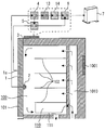
- FIG. 2 shows the configuration of the refrigerator system in the house and the configuration of the refrigerator compartment of the refrigerator.
- FIG. 3 is a diagram schematically illustrating the first communication method of the refrigerator system
- FIG. 4 is a diagram illustrating the second communication method of the refrigerator system
- FIG. 5 is a flowchart illustrating the operation of the refrigerator system. It is.
- the refrigerator system according to Embodiment 1 of the present invention includes a refrigerator 1000.
- Refrigerator 1000 is a refrigerator body in the refrigerator system according to Embodiment 1 of the present invention.
- the refrigerator 1000 is formed with a refrigerating room 100, an ice making room 200, a switching room 300, a freezing room 400, and a vegetable room 500.
- the refrigerator compartment 100, the ice making room 200, the switching room 300, the freezing room 400, and the vegetable room 500 are storage rooms for storing food.
- these storage rooms are arranged in the order of a refrigerator room 100, an ice making room 200, a switching room 300, a freezer room 400, and a vegetable room 500 from the top.
- the ice making chamber 200 and the switching chamber 300 are arranged side by side at the same vertical position.
- a refrigerator compartment door 101 for opening and closing the refrigerator compartment 100 is provided on the front face of the refrigerator compartment 100.
- the refrigerator compartment door 101 is an example of a door that opens and closes a storage compartment.
- the ice making room 200, the switching room 300, the freezer room 400, and the vegetable room 500 are comprised so that it can pull out to the near side of the refrigerator 1000 with the door provided in each front.
- the operation panel 1 is provided in front of the refrigerator compartment door 101.
- the operation panel 1 includes a panel display unit 1a.
- the panel display unit 1a is a main body display unit capable of displaying information.
- the panel display unit 1a can display, for example, in-chamber information such as the set temperature of each storage room and the current temperature.
- the panel display unit 1a includes a liquid crystal display, for example.
- the operation panel 1 includes operation units such as a touch panel, buttons, and switches. The user can input necessary information by operating the operation unit of the operation panel 1.
- the installation position of the operation panel 1 is not restricted to the door of the refrigerator compartment 100, The door of another storeroom, the side surface of the refrigerator 1000, etc. may be sufficient.
- the refrigerator compartment 100 has its front side (left side as viewed in the figure) closed by a refrigerator compartment door 101.
- the cross-sectional view shown in FIG. 2 is taken along a cross-section A-A ′ in FIG.
- a plurality of refrigerating room shelf plates 102 are provided inside the refrigerating room 100.
- the inside of the refrigerator compartment 100 is partitioned into a plurality of spaces (shelves) in the vertical direction by these refrigerator compartment shelf plates 102.
- the space below the lowermost refrigerator compartment shelf 102 is a chilled chamber 110.
- a chilled case 111 is installed inside the chilled chamber 110.
- the chilled case 111 can be pulled forward along a guide member (not shown) such as a rail.
- a cooling air passage 1010 is formed on the rear side (right side in the drawing) of the refrigerator compartment 100.
- the inside photographing device 2 is installed on the inner surface of the refrigerator compartment door 101.
- the in-compartment photographing device 2 is a camera that photographs the inside of a storage room (here, the refrigerator compartment 100) and outputs a storage room image.
- the in-compartment photographing apparatus 2 has a visual field range from the ceiling surface inside the refrigerator compartment 100 to the chilled room 110. That is, the in-compartment photographing apparatus 2 can photograph the inside of the refrigerator compartment 100 from the same viewpoint as the user who has seen the inside of the refrigerator compartment 100 from the refrigerator compartment door 101 side.
- the inside photographing apparatus 2 photographs the inside of the refrigerator compartment 100 when the refrigerator compartment door 101 is opened and closed, for example. This is because when the refrigerator compartment door 101 is opened and closed, food in the refrigerator compartment 100 is taken in and out, and the storage state in the refrigerator compartment 100 may change.
- the refrigerator 1000 includes a sensor that can detect opening and closing of the door. This sensor is, for example, a general magnet type sensor. That is, this sensor detects, for example, the proximity of the magnet embedded in the refrigerator door 101 by a pair of reed switches installed on the refrigerator 1000 main body side. For example, the in-compartment photographing apparatus 2 performs photographing while the inside of the refrigerator compartment 100 is illuminated after detecting that the opened refrigerator compartment door 101 is closed.
- the installation position of the internal photographing apparatus 2 is not limited to the inner surface of the refrigerator compartment door 101 as shown in FIG.
- the in-compartment photographing apparatus 2 may be installed anywhere as long as it can photograph a stored item such as food placed on the refrigerator compartment shelf board 102.
- the number of in-compartment photographing apparatuses 2 is not limited to one. That is, you may install the some imaging
- the refrigerator 1000 includes a control board 1001.
- the control board 1001 is accommodated in the upper part on the back side of the refrigerator 1000, for example.
- the control board 1001 is provided with a control circuit and the like for performing various controls necessary for the operation of the refrigerator 1000.
- the control board 1001 includes, for example, a microcomputer, that is, includes a processor and a memory.
- the control board 1001 controls the refrigerator 1000 by executing a preset process when the processor executes a program stored in the memory.
- the refrigerator system according to Embodiment 1 of the present invention includes an image server 3.
- the image server 3 is for storing, managing, and transmitting the storage room image to the outside.
- the image server 3 is installed in the house where the refrigerator 1000 is installed (hereinafter simply referred to as “home”) and outside the storage room of the refrigerator 1000.
- 1 and 2 show an example in which the image server 3 is arranged on the outer surface of the ceiling of the refrigerator 1000.
- the installation position of the image server 3 is not limited to the ceiling portion of the refrigerator 1000. If the image server 3 is outside the storage room of the refrigerator 1000, the image server 3 may be installed on the side surface, the back surface of the refrigerator 1000, or the door of the storage room. Further, the image server 3 may be mounted on the control board 1001.
- the image server 3 includes, for example, a microcomputer as in the control board 1001 described above, that is, includes a processor and a memory. Further, as shown in FIG. 2, the image server 3 includes a storage room image storage unit 4, a storage room image management unit 5, and a wireless communication unit 6. The functions of these units are realized, for example, in the microcomputer of the image server 3 by the processor executing a program stored in the memory and performing a preset process.
- the image server 3 is connected to, for example, the control board 1001 and operates with power supplied from the control board 1001.
- the storage room image storage unit 4 is a first image storage unit that stores the storage room image output from the internal photographing apparatus 2. As described above, when opening / closing of the refrigerator compartment door 101 is detected, the in-compartment photographing apparatus 2 photographs the entire inside of the refrigerator compartment 100. The in-compartment photographing apparatus 2 outputs the entire image (stored room image) in the refrigerating room 100 taken to the storage room image storage unit 4. The storage room image output from the internal photographing apparatus 2 is input to the storage room image storage unit 4. Therefore, every time the refrigerator compartment door 101 is opened and closed (that is, every time the storage state in the refrigerator compartment 100 may change), the storage room image storage unit 4 outputs the storage compartment image storage unit 4. A storage room image is input. Thus, the latest storage room image is always input to the storage room image storage unit 4.
- the storage room image storage unit 4 temporarily stores the latest input storage room image. At this time, the storage room image storage unit 4 temporarily stores the time when the storage room image was input to the storage room image storage unit 4 together with the storage room image as photographing time information. Note that the shooting time information includes information on the date (month or date) when the image was taken.
- the storage room image management unit 5 is a second image storage unit that stores the storage room image stored in the storage room image storage unit 4 that is the first image storage unit.
- the storage room image management unit 5 acquires the storage room image and shooting time information temporarily stored in the storage room image storage unit 4 from the storage room image storage unit 4.
- the storage room image management unit 5 rearranges and stores the acquired storage room images in the order of the shooting times based on the shooting time information. In this way, the storage room image photographed by the in-compartment photographing device 2 is temporarily stored in the storage room image storage unit 4 and then moved to the storage room image management unit 5 for management.
- the storage room image managed and stored in the storage room image management unit 5 can be displayed on the panel display unit 1a of the operation panel 1 together with the photographing time information.
- the wireless communication unit 6 is a communication device that can communicate with the outside.
- the wireless communication unit 6 performs mutual communication of information between the image server 3 of the refrigerator 1000 and the router device 7 using, for example, a known wireless communication technique.
- the communication between the image server 3 and the router device 7 is not limited to the wireless method, and may be a wired method.
- the refrigerator system according to Embodiment 1 of the present invention includes a user terminal 10.
- the user terminal 10 is a terminal device provided to be able to communicate with the wireless communication unit 6 that is a communication device.
- the user terminal 10 is, for example, a PC, a smartphone, a tablet terminal, or the like.
- One or more user terminals 10 are provided, and preferably a plurality of user terminals 10 are provided.
- the user terminal 10 includes a terminal display unit (not shown).
- the terminal display unit includes, for example, a liquid crystal display.
- the terminal display unit may be configured with a touch panel to display information and accept operations from the user.
- the terminal display unit of the user terminal 10 can display various types of information including storage room images and shooting time information.
- the wireless communication unit 6 is configured to be able to switch between two communication methods. That is, the wireless communication unit 6 that is a communication device can switch between the first communication method and the second communication method.
- the first communication method is a communication method for transmitting the storage room image stored in the storage room image storage unit 4 as the first image storage unit to an external server.
- the router device 7 is communicably connected to the cloud server 9 via the Internet 8, for example.
- the cloud server 9 is the external server described above. In the figure, a case where a cloud server 9 composed of a plurality of servers (server group) connected to the Internet 8 is used as an external server is illustrated. However, the external server is not limited to the cloud server 9 and may be a single server.
- the Internet 8 and the cloud server 9 are outside the house where the refrigerator 1000 is installed (hereinafter simply referred to as “outside the house”).
- the second communication method is a communication method for transmitting the storage room image stored in the storage room image management unit 5, which is the second image storage unit, to the user terminal 10.
- the wireless communication unit 6 selects the first communication method in the initial setting. Therefore, as shown in FIG. 3, the wireless communication unit 6 transmits the latest storage room image temporarily stored in the storage room image storage unit 4 to the cloud outside the home via the router device 7 and the Internet 8. Send to server 9. Then, the cloud server 9 stores the received storage room image. At this time, it is preferable that the shooting time information corresponding to the storage room image is also transmitted and the cloud server 9 stores the storage room image and the shooting time information.
- the maximum number of retries for uploading the storage room image from the wireless communication unit 6 to the cloud server 9 May be set.
- the wireless communication unit 6 may immediately upload when the maximum number of retries is reached.
- the user terminal 10 receives the storage room image from the external server. That is, in this case, the user terminal 10 outside the home accesses the cloud server 9 via the Internet 8.
- the user terminal 10 transmits a storage room image transmission request.
- the cloud server 9 that has received the storage room image transmission request transmits the storage room image and the photographing time information stored therein to the user terminal 10.
- the user terminal 10 receives the storage room image and the shooting time information from the cloud server 9 via the Internet 8. Then, the user terminal 10 displays the received storage room image and shooting time information on the terminal display unit.
- the wireless communication unit 6 is configured to be able to switch to the second communication method in response to a request from the user terminal 10 in the house when the first communication method is selected.
- the wireless communication unit 6 displays the storage room image stored in the storage room image management unit 5 as To the user terminal 10 at home.
- the photographing time information corresponding to the storage room image may be transmitted together.
- the user terminal 10 receives the storage room image stored in the storage room image management unit 5 from the wireless communication unit 6. That is, in this case, when the user performs a display operation of the storage room image on the user terminal 10, the user terminal 10 transmits a storage room image transmission request.
- the wireless communication unit 6 that has received the storage room image transmission request transmits the storage room image and shooting time information stored in the storage room image management unit 5 to the user terminal 10 in the house.
- the user terminal 10 in the home receives the storage room image and the shooting time information transmitted from the wireless communication unit 6 via the router device 7 in the home. Then, the user terminal 10 displays the received storage room image and shooting time information on the terminal display unit.
- a router device 7 having a function of automatically setting a wireless communication connection with the wireless communication unit 6 or the like of the image server 3.
- the wireless communication unit 6 manually operates the router device by operating the user terminal 10 in the second communication method. 7 and the wireless communication unit 6 of the image server 3 are preferably set so that the wireless communication connection can be set.
- the storage room image can also be confirmed on the operation panel 1 of the refrigerator 1000 at home. For this reason, it is considered that there are actually more cases in which the first communication method is used than in the second communication method. For this reason, as described above, the wireless communication unit 6 may select the first communication method in the initial setting.
- the wireless communication unit 6 may select the first communication method when a predetermined time has elapsed after selecting the second communication method. For example, when the user goes out while being set to the second communication method limited to browsing from home, the latest storage room image stored in the storage room image storage unit 4 is not uploaded to the cloud server 9. . For this reason, the user cannot confirm the latest storage room image from outside the house. In preparation for such a case, when the second communication method is set to check the storage room image in the house, the first communication method is automatically changed after a predetermined time has elapsed. Is good.
- the wireless communication unit 6 selects either the first communication method or the second communication method depending on whether the user terminal 10 that transmitted the storage room image transmission request is out of the house or in the house. You may make it determine whether to do.
- the wireless communication unit 6 that has received the storage room image transmission request from the user terminal 10 checks whether the user terminal 10 that has transmitted the storage room image transmission request is in the house or outside the house. This confirmation is possible, for example, by confirming the transmission path of the storage room image transmission request and confirming whether the storage room image transmission request is transmitted from inside the house or from outside the house. .
- the transmission path of the storage room image transmission request can be confirmed by using, for example, a known network management command.
- the wireless communication unit 6 When receiving the storage room image transmission request from the user terminal 10 outside the home, the wireless communication unit 6 selects the first communication method. Accordingly, the wireless communication unit 6 transmits the latest storage room image stored in the storage room image storage unit 4 to the cloud server 9. The user terminal 10 outside the home receives the storage room image from the cloud server 9.
- the wireless communication unit 6 selects the second communication method. Therefore, the wireless communication unit 6 transmits the storage room image stored in the storage room image management unit 5 to the user terminal 10 in the home.
- the user terminal 10 in the home receives the storage room image from the wireless communication unit 6 via the router device 7.
- the user can check the storage room image of the refrigerator 1000 via the Internet 8 and the cloud server 9 even outside the home.
- the second communication method as described above only the local communication network closed in the house is used. For this reason, the user inputs the access code of the router device 7 and the address (URL) of the image server 3 to the user terminal 10, whereby information such as the storage room image stored in the image server 3 is stored in the user terminal at home. 10 can be viewed.
- FIG. 3 shows an example in which a personal authentication device 11 as an authentication unit is provided in the cloud server 9. The personal authentication device 11 authenticates whether or not the user terminal 10 has the authority to receive the storage room image of the refrigerator 1000.
- the personal authentication device 11 of the cloud server 9 stores in advance the terminal device ID of the user terminal 10 having authority to connect to the refrigerator 1000 with respect to the ID of the refrigerator 1000.
- the ID of the refrigerator 1000 is refrigerator identification information that can uniquely identify a plurality of refrigerators 1000 connected to the Internet 8.
- the terminal device ID is terminal device identification information that can uniquely identify a plurality of user terminals 10 connected to the Internet 8.
- the personal authentication device 11 confirms whether or not the portable terminal ID of the user terminal 10 is stored as having the authority to receive the storage room image of the refrigerator 1000 with respect to the ID of the refrigerator 1000. If the portable terminal ID of the user terminal 10 is stored as having the authority to receive the storage room image of the refrigerator 1000 with respect to the ID of the refrigerator 1000, the personal authentication device 11 is Authenticate that you have the authority to receive storage room images.
- the storage room image is stored in one or both of the storage room image management unit 5 and the cloud server 9 in association with the ID of the refrigerator 1000 in which the storage room image is taken.
- the storage room image stored in the cloud server 9 is associated with the ID of the refrigerator 1000 in which the storage room image was taken.
- the cloud server 9 permits the user terminal 10 that has been authorized by the personal authentication device 11 to have the authority to receive the storage room image of the refrigerator 1000 to receive the storage room image of the refrigerator 1000. In other words, the cloud server 9 restricts the user terminal 10 that is not authenticated by the personal authentication device 11 from having the authority to receive the storage room image of the refrigerator 1000 from receiving the storage room image of the refrigerator 1000. To do.
- the personal authentication device 11 By providing the personal authentication device 11 as described above, even if the access code (for example, the SSID and the encryption key) of the router device 7 is leaked, the terminal other than the registered user terminal 10 is connected to the cloud server 9 or the image. It is possible to prevent the storage room image from being received by accessing the server 3.
- the access code for example, the SSID and the encryption key
- the personal authentication device 11 described above authenticates authority using an ID.
- This authentication method is not limited to this.
- the authority may be authenticated by biometric authentication such as fingerprints, veins, and irises of the eyes, authentication by password, or a combination of these authentication methods.
- the above-described sensor detects opening and closing of the refrigerator door 101.
- opening / closing of the refrigerator compartment door 101 the process proceeds from step S11 to step S12.
- step S12 the in-compartment photographing apparatus 2 photographs the inside of the refrigerator compartment 100 that is a storage room.
- the process proceeds to step S13.
- step S13 the in-compartment photographing device 2 transmits the image inside the refrigerator compartment 100 photographed in step S12 to the storage room image storage unit 4 as a storage room image.
- the storage room image storage unit 4 stores the storage room image photographed by the internal photographing apparatus 2 in step S12 together with photographing time information.
- step S14 the process proceeds to step S14.
- step S14 the storage room image storage unit 4 transmits the storage room image and the photographing time information received in step S13 to the storage room image management unit 5.
- step S15 the storage room image management unit 5 stores the storage room images transmitted from the storage room image storage unit 4 in the order of the shooting time based on the shooting time information.
- step S16 the process proceeds to step S16.
- step S ⁇ b> 16 the storage room image management unit 5 transmits the storage room image and the shooting time information to the operation panel 1.
- the operation panel 1 displays the received storage room image and shooting time information on the panel display unit 1a.
- step S17 the wireless communication unit 6 confirms whether or not the first communication method is currently selected. If the first communication method is selected, the process proceeds to step S18.
- step S ⁇ b> 18 the wireless communication unit 6 transmits the storage room image and the shooting time information temporarily stored in the storage room image storage unit 4 to the cloud server 9 outside the home via the router device 7 and the Internet 8. Upload to. After step S18, the process proceeds to step S19.
- step S17 if the first communication method is not selected in step S17, the second communication method is currently selected. In this case, the process proceeds directly from step S17 to step S19 without passing through step S18.
- step S19 and subsequent step S20 the subject that performs the process differs depending on whether or not the process of step S18 is executed.
- the cloud server 9 stores the storage room from the user terminal 10. Check whether an image transmission request has been received.
- step S18 if the process of step S18 is not executed, that is, if the second communication method is selected, has the wireless communication unit 6 received the storage room image transmission request from the user terminal 10? Confirm whether or not.
- step S11 If the storage room image transmission request from the user terminal 10 is not received, the process returns to step S11. On the other hand, when the storage room image transmission request from the user terminal 10 is received, the process proceeds to step S20.
- step S20 when the first communication method is selected, the cloud server 9 transmits the storage room image and the shooting time information to the user terminal 10.
- the wireless communication unit 6 transmits the storage room image and the photographing time information to the user terminal 10. Then, the user terminal 10 displays the received storage room image and shooting time information on the terminal display unit.
- the inside photographing device 2 is provided in the refrigerator compartment 100
- the installation location of the in-compartment photographing apparatus 2 is not limited to this example.
- the in-compartment photographing apparatus 2 may be provided in a storage room other than the refrigerator compartment 100, or may be installed in a plurality of storage rooms at the same time.
- the vegetable room 500 is a storage room in which vegetables that are easily deteriorated are stored in addition to being difficult to grasp the internal situation compared to other storage rooms. Therefore, by installing the in-compartment photographing apparatus 2 in the vegetable room 500, the user can check an image obtained by photographing the inside of the vegetable room 500 from outside the house. Therefore, the user can easily grasp the expiration date of the food stocked in the vegetable compartment 500, and can reduce the possibility of passing the expiration date and discarding the food.
- the user can grasp the storage status of frozen meat, rice, etc., which are the main ingredients of the meal. Furthermore, frozen food needs to be stored in the freezer compartment 400 when purchased. If the freezer compartment 400 has the in-compartment photographing device 2, the storage amount of the freezer compartment 400 can be shared by a plurality of users such as family members, and thus the user can determine the amount of frozen food purchased from outside the house. .
- the refrigerator system configured as described above includes a refrigerator 1000 in which a storage room for storing food is formed, an in-camera imaging device 2 that images the interior of the storage room and outputs the image as a storage room image, and an in-house imaging device.
- the storage room image storage unit 4 that stores the storage room image output from 2
- the storage room image management unit 5 that stores the storage room image stored in the storage room image storage unit 4, and wireless communication that can communicate with the outside
- a user terminal 10 capable of communicating with the wireless communication unit 6.
- the wireless communication unit 6 uses the first communication method for transmitting the storage room image stored in the storage room image storage unit 4 to the cloud server 9 and the storage room image stored in the storage room image management unit 5 as the user.
- the second communication method to be transmitted to the terminal 10 can be switched. Further, when the wireless communication unit 6 selects the first communication method, the user terminal 10 receives the storage room image from the cloud server 9, and the wireless communication unit 6 selects the second communication method. If it is, the storage room image stored in the storage room image management unit 5 is received from the wireless communication unit 6.
- all the storage room images managed by the storage room image management unit 5 can be confirmed from the user terminal 10 in the house without going through a communication network outside the house such as the Internet 8.
- the latest storage room image can be confirmed via the cloud server 9 also on the user terminal 10 outside the home.
- the latest storage room image of the refrigerator main body can be confirmed from both the in-home and outside user terminals where the refrigerator main body is installed, and communication between the in-house wireless communication unit 6 and the outside device is necessary.
- Opportunities can be reduced as much as possible to reduce communication loads and costs, and to reduce security risks such as the risk of information leaking to the Internet and the occurrence of security holes.
- the opportunity of communication between the home wireless communication unit 6 and the outside device can be greatly reduced particularly for the following two reasons.
- the cloud server 9 is the only device outside the home with which the wireless communication unit 6 in the home communicates.
- the user terminal outside the home accesses the external server to check whether the storage room image has been updated, once the latest storage room image is uploaded to the external server, Until the storage room image is updated, there is no need to communicate between the image server in the house and the external server outside the house.
- FIG. 6 and 7 relate to Embodiment 2 of the present invention.
- FIG. 6 is a diagram for explaining a case where a storage room image is transmitted to a plurality of user terminals in the refrigerator system
- FIG. It is a figure explaining the case where the storage room image of a refrigerator is transmitted to a user terminal.
- image server identification information capable of uniquely identifying the image server from a plurality of image servers is assigned to the image server. is there.
- the refrigerator system according to the second embodiment will be described with a focus on differences from the first embodiment.
- FIG. 6 shows an example of a situation in which storage room images are transmitted from one image server 3 to a plurality of user terminals 10 in the house.
- the image server identification number 12 is assigned to the image server 3 corresponding to the refrigerator 1000.
- the image server identification number 12 is image server identification information that can uniquely identify a specific image server 3 from a plurality of image servers 3.
- the user terminal 10 can connect to the image server 3 specified by the image server identification number 12 using the image server identification number 12 which is the image server identification information.
- the refrigerator system in this example includes a plurality of user terminals 10 including a first user terminal 10a, a second user terminal 10b, and a third user terminal 10c.
- a plurality of user terminals 10 in the house can be connected to the image server 3 at the same time.
- the second communication method when each of the first user terminal 10a, the second user terminal 10b, and the third user terminal 10c receives the storage room image of the refrigerator 1000 from the image server 3,
- the first user terminal 10a, the second user terminal 10b, and the third user terminal 10c specify the same image server identification number 12 in common and connect to the image server 3.
- the common image server identification number 12 can also be used when a user other than the user who is normally used, for example, a serviceman who has visited for repair connects to the image server 3. However, in this case, it is desirable to set an access code dedicated to the service person, which is different from the user who owns the refrigerator 1000.
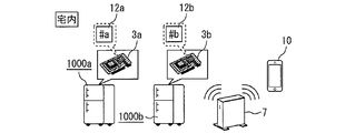
- FIG. 7 shows an example of a situation in which one user terminal 10 in the home acquires storage room images stored in a plurality of image servers 3.
- a plurality of refrigerators 1000 including a first refrigerator 1000a and a second refrigerator 1000b are installed in the house.
- a first image server 3a is provided corresponding to the first refrigerator 1000a.
- a second image server 3b is provided corresponding to the second refrigerator 1000b.
- the first image server identification number 12a is assigned to the first image server 3a corresponding to the first refrigerator 1000a.
- the second image server identification number 12b is assigned to the second image server 3b corresponding to the second refrigerator 1000b.
- the first image server identification number 12a and the second image server identification number 12b are both the above-described image server identification information.
- the user terminal 10 can connect to the image server 3 specified by the image server identification number 12 by using the image server identification number 12 that is the image server identification information.
- the user terminal 10 when the user terminal 10 receives the storage room image of the first refrigerator 1000a from the first image server 3a, the user terminal 10 specifies the first image server identification number 12a, Connect to the first image server 3a. Further, when the user terminal 10 receives the storage room image of the first refrigerator 1000a from the second image server 3b, the user terminal 10 designates the second image server identification number 12b, and the second image server Connect to 3b.
- the storage room images of a plurality of refrigerators 1000 can be displayed.
- a plurality of user terminals 10 may be simultaneously connected to the cloud server 9 outside the house. By doing in this way, the storage room image of the refrigerator 1000 of the parent who lives far away can be confirmed from the child user terminal 10 as well as the parent user terminal 10. It is also possible to confirm both the storage room image of the parent refrigerator 1000 and the storage room image of the child's own refrigerator 1000 from the child user terminal 10.
- the same effects as in the first embodiment can be obtained. Furthermore, even when the system includes a plurality of refrigerators 1000 or a plurality of user terminals 10, it is possible to easily and reliably perform communication setting and transmission / reception of storage room images.
- FIG. FIGS. 8 to 13 relate to Embodiment 3 of the present invention.
- FIG. 8 is a diagram schematically showing the configuration of the interior of the refrigerator system and the refrigerator compartment, and FIG. The figure which shows an example of a storage room image, FIGS. 10-12 is a figure which respectively shows the 1st-3rd example of the storage room image after the process of a refrigerator system, FIG. 13 is a flowchart explaining operation
- the third embodiment described here is a storage room stored in the first image storage unit when the first communication method is selected in the configuration of the first or second embodiment.
- the communication device transmits the image to an external server after processing the image.
- the refrigerator system according to the third embodiment will be described by focusing on the differences from the first embodiment, taking as an example the case based on the configuration of the first embodiment.
- the image server 3 includes an image processing unit 13 and a processed image storage unit 14 as shown in FIG.
- the image processing unit 13 processes the storage room image stored in the storage room image storage unit 4 that is the first image storage unit.
- the image processing unit 13 preferably includes a processor capable of high-speed image processing in order to smoothly perform image processing.
- the operating frequency of such a processor is specifically 400 MHz or more, for example.
- the image processing unit 13 transmits the processed storage room image and the shooting time information of the storage room image to the processed image storage unit 14. Specific contents of the processing of the storage room image by the image processing unit 13 will be described later.
- the processed image storage unit 14 is for storing the storage room image processed by the image processing unit 13 until the wireless communication unit 6 transmits it.
- the processed image storage unit 14 acquires the storage room image and the photographing time information after being processed by the image processing unit 13.
- storage part 14 rearranges and memorize
- the processed image storage unit 14 may classify and store the acquired storage room images after processing for each processing method performed by the image processing unit 13.
- the wireless communication unit 6 transfers the storage room image stored in the processed image storage unit 14 to the cloud server 9 outside the home via the router device 7 and the Internet 8. And send. Therefore, the wireless communication unit 6 that is a communication device transmits an image obtained by processing the storage room image stored in the storage room image storage unit 4 to the cloud server 9 that is an external server.
- the cloud server 9 receives the processed storage room image transmitted from the wireless communication unit 6. Then, the cloud server 9 stores the received processed storage room image. The user terminal 10 outside the home receives the processed storage room image from the cloud server 9 via the Internet 8.
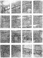
- FIG. 9 shows an example of a storage room image temporarily stored in the storage room image storage unit 4. That is, FIG. 9 shows an example of the storage room image before the processing by the image processing unit 13 is performed.
- FIG. 10 shows a first example of the storage room image after the image processing unit 13 processes the storage room image of FIG.
- the image processing unit 13 performs a process of reducing the resolution of the storage room image.
- the image processing unit 13 averages pixels in a certain range and reduces the image size with respect to the image of the entire storage room as illustrated in FIG. 9, and then maintains the original resolution while maintaining the reduced resolution.
- the resolution of the storage room image is reduced.
- the whole image as shown in FIG. 9 is compressed to an image size of 1/8, and the resolution is set to 1/8 of the original image.
- the user can roughly grasp the situation inside the storage room such as the refrigerator compartment 100 or the like.
- the amount of communication data can be reduced in the processed image of FIG. Therefore, by adjusting the reduction rate of resolution, the communication speed at the time of image uploading is improved. For example, even in a remote place, the time lag from the transmission of the storage room image transmission request to the reception of the storage room image Can be shortened.
- FIG. 11 shows a second example of the storage room image after the processing by the image processing unit 13.
- the image processing unit 13 performs a process of dividing the storage room image into a plurality of parts.
- the image processing unit 13 divides the entire storage room image as shown in FIG. 9 by, for example, a preset division number.
- the image processing unit 13 may divide the storage room image so that the image size after the division is equal to or less than a preset value.
- the example shown in FIG. 10 is obtained by dividing the entire image as shown in FIG. 9 into 16 equal area regions.
- the divided images are transmitted one by one in order. That is, it is possible to reduce the amount of communication data when transmitting one divided image. Therefore, it is possible to improve the communication speed when uploading images.
- a desired area can be stored with a small amount of communication data while maintaining the resolution of the image. The user can check the storage status.
- FIG. 12 shows a third example of the storage room image after the processing by the image processing unit 13.
- the image processing unit 13 performs a process of extracting a portion where the food in the storage room is photographed from the storage room image.
- the image processing unit 13 stores in advance an initial image in which the inside photographing apparatus 2 has photographed the storage room in a state where no food is stored.
- the image processing unit 13 calculates the difference between the storage room image photographed by the internal photographing device 2 and the initial image. Then, the image processing unit 13 extracts a portion that has changed from the initial image as a portion where food is arranged.
- the processed image of FIG. 12 transmits the images after food extraction one by one in order. It is possible to reduce the amount of communication data when transmitting a single image in which the food is extracted. Therefore, it is possible to improve the communication speed when uploading images.
- the user can obtain only images of stock food stocked in the storage room of the refrigerator 1000. For this reason, the user can confirm stock food quickly and easily. Accordingly, for example, at a shopping destination, the user can grasp the stock status from the food extraction image and prevent over-buying or forgetting to purchase food.
- steps S11 to S17 in the flowchart of FIG. 13 are the same as the contents of steps S11 to S17 in the flowchart of FIG. 5 described in the first embodiment. Therefore, description of these steps is omitted here.
- movement flow of FIG. 13 of this Embodiment 3 when the 1st communication system is currently selected by step S17, a process progresses to step S21.
- step S21 the storage room image storage unit 4 transmits the last storage room image and shooting time information stored therein to the image processing unit 13. After step S21, the process proceeds to step S22.
- step S ⁇ b> 22 the image processing unit 13 performs a preset image processing process on the storage room image received from the storage room image storage unit 4. Then, the image processing unit 13 transmits the processed storage room image and the shooting time information of the storage room image to the processed image storage unit 14. After step S22, the process proceeds to step S18.
- step S ⁇ b> 18 the wireless communication unit 6 transmits the processed storage room image and shooting time information stored in the processed image storage unit 14 to the cloud server 9 outside the home via the router device 7 and the Internet 8. And upload.
- step S18 the process proceeds to step S19.
- step S17 if the first communication method is not selected in step S17, the second communication method is currently selected. In this case, the process proceeds directly from step S17 to step S19 without passing through steps S21, S22, and S18.
- step S19 and subsequent step S20 the subject that performs the process differs depending on whether or not the processes in steps S21, S22, and S18 are executed.
- steps S21, S22, and S18 are executed and the processed storage room image is uploaded to the cloud server 9, that is, when the first communication method is selected, the cloud server 9 It is confirmed whether a storage room image transmission request from the user terminal 10 has been received.
- the wireless communication unit 6 requests the storage room image transmission from the user terminal 10. Confirm whether or not.
- step S11 If the storage room image transmission request from the user terminal 10 is not received, the process returns to step S11. On the other hand, when the storage room image transmission request from the user terminal 10 is received, the process proceeds to step S20.
- step S20 when the first communication method is selected, the cloud server 9 transmits the processed storage room image and shooting time information to the user terminal 10.
- the wireless communication unit 6 transmits the storage room image and the photographing time information to the user terminal 10. Then, the user terminal 10 displays the received processed or unprocessed storage room image and shooting time information on the terminal display unit.
- step S20 the process returns to step S11.
- the refrigerator system configured as described above can achieve the same effects as those of the first embodiment or the second embodiment.
- the captured storage room image is captured by the image processing unit 13.
- the communication load can be reduced. Therefore, it is possible to shorten the time required for connection to the cloud server 9 via the Internet 8.
- the present invention includes a refrigerator body in which a storage room for storing food is formed, and a camera that captures an image of the interior of the storage room and outputs the image as a storage room image.
- the storage room image output from the camera is stored in the terminal device. It can be used for refrigerator system to display.
Abstract
宅内及び宅外のユーザ端末から最新の貯蔵室画像を確認でき、かつ、宅内外での通信機会を極力減らすことができる冷蔵庫システムを提供する。このため、冷蔵庫システムは、庫内撮影装置(2)から出力された冷蔵庫(1000)の貯蔵室画像を記憶する貯蔵室画像記憶部(4)と、貯蔵室画像記憶部(4)に記憶された貯蔵室画像を記憶する貯蔵室画像管理部(5)と、無線通信部(6)と、ユーザ端末(10)と、を備える。無線通信部(6)は、貯蔵室画像記憶部(4)に記憶された貯蔵室画像をクラウドサーバ(9)に送信する第1の通信方式と、貯蔵室画像管理部(5)に記憶された貯蔵室画像をユーザ端末(10)に送信する第2の通信方式とを切り換え可能である。ユーザ端末(10)は、第1の通信方式ではクラウドサーバ(9)から貯蔵室画像を受信し、第2の通信方式では無線通信部(6)から貯蔵室画像を受信する。
Description
この発明は、冷蔵庫システムに関するものである。
庫内を撮像する撮像手段を備えた食品保存庫と、食品保存庫内の撮像画像を蓄積し、かつ情報ネットワークに接続されたローカルデータベースとを有するホームネットワーク装置を備え、携帯情報端末によりインターネット等の情報ネットワークを通じてホームネットワーク装置にアクセスし、ローカルデータベースに保持されている食品保存庫内の撮像画像をダウンロードしてディスプレイに表示する冷蔵庫システムが知られている(例えば、特許文献1参照)。
しかしながら、特許文献1に示されるような冷蔵庫システムにおいては、携帯情報端末であるユーザ端末で、食品保存庫である冷蔵庫の貯蔵室内の画像(以下、「貯蔵室画像」という)を確認する際、ユーザ端末から常にインターネット等の外部の情報ネットワークを通じて、ホームネットワーク内のローカルデータベースに接続することになる。このため、まず第1に、冷蔵庫本体が設置された宅内の通信装置と宅外の機器との通信機会が多くなり、通信負荷及び通信費用が増大してしまう。また、第2には、宅内の通信装置と宅外の機器との通信機会が多くなることで、インターネット上への情報流出のリスク及びセキュリティホールの発生等のセキュリティリスクが大きくなることが懸念される。
この発明は、このような課題を解決するためになされたものである。その目的は、冷蔵庫本体が設置された宅内及び宅外の両方のユーザ端末から、冷蔵庫本体の最新の貯蔵室画像を確認でき、かつ、宅内の通信装置と宅外の機器との通信が必要な機会を極力減らし、通信負荷及び通信費用の削減、並びに、インターネット上への情報流出のリスク及びセキュリティホールの発生等のセキュリティリスクの低減を図ることが可能である冷蔵庫システムを得ることにある。
この発明に係る冷蔵庫システムは、食品を収納する貯蔵室が形成された冷蔵庫本体と、前記貯蔵室の内部を撮影し、貯蔵室画像として出力するカメラと、前記カメラから出力された貯蔵室画像を記憶する第1の画像記憶部と、前記第1の画像記憶部に記憶された貯蔵室画像を記憶する第2の画像記憶部と、外部と通信可能な通信装置と、前記通信装置と通信可能な端末装置と、を備え、前記通信装置は、前記第1の画像記憶部に記憶された貯蔵室画像を外部サーバに送信する第1の通信方式と、前記第2の画像記憶部に記憶された貯蔵室画像を前記端末装置に送信する第2の通信方式とを切り換え可能であり、前記端末装置は、前記通信装置が前記第1の通信方式を選択している場合に、前記外部サーバから貯蔵室画像を受信し、前記通信装置が前記第2の通信方式を選択している場合に、前記第2の画像記憶部に記憶された貯蔵室画像を前記通信装置から受信する。
この発明に係る冷蔵庫システムにおいては、冷蔵庫本体が設置された宅内及び宅外の両方のユーザ端末から、冷蔵庫本体の最新の貯蔵室画像を確認でき、かつ、宅内の通信装置と宅外の機器との通信が必要な機会を極力減らし、通信負荷及び通信費用の削減、並びに、インターネット上への情報流出のリスク及びセキュリティホールの発生等のセキュリティリスクの低減を図ることが可能であるという効果を奏する。
この発明を実施するための形態について添付の図面を参照しながら説明する。各図において、同一又は相当する部分には同一の符号を付して、重複する説明は適宜に簡略化又は省略する。なお、本発明は以下の実施の形態に限定されることなく、本発明の趣旨を逸脱しない範囲で種々変形することが可能である。
実施の形態1.
図1から図5は、この発明の実施の形態1に係るもので、図1は冷蔵庫システムが備える冷蔵庫の正面図、図2は冷蔵庫システムの宅内側の構成と冷蔵庫の冷蔵室の構成とを模式的に示す図、図3は冷蔵庫システムの第1の通信方式を説明する図、図4は冷蔵庫システムの第2の通信方式を説明する図、図5は冷蔵庫システムの動作を説明するフロー図である。
図1から図5は、この発明の実施の形態1に係るもので、図1は冷蔵庫システムが備える冷蔵庫の正面図、図2は冷蔵庫システムの宅内側の構成と冷蔵庫の冷蔵室の構成とを模式的に示す図、図3は冷蔵庫システムの第1の通信方式を説明する図、図4は冷蔵庫システムの第2の通信方式を説明する図、図5は冷蔵庫システムの動作を説明するフロー図である。
この発明の実施の形態1に係る冷蔵庫システムは、冷蔵庫1000を備えている。冷蔵庫1000は、この発明の実施の形態1に係る冷蔵庫システムにおける冷蔵庫本体である。この実施の形態1においては、冷蔵庫1000には、冷蔵室100、製氷室200、切替室300、冷凍室400及び野菜室500が形成されている。これらの冷蔵室100、製氷室200、切替室300、冷凍室400及び野菜室500は、食品を収納する貯蔵室である。
これらの貯蔵室は、図1に示すように、上から冷蔵室100、製氷室200及び切替室300、冷凍室400、野菜室500の順で配置されている。製氷室200と切替室300とは、同じ上下位置において左右に並んで配置されている。冷蔵室100の前面には、冷蔵室100を開閉する冷蔵室扉101が設けられている。冷蔵室扉101は、貯蔵室を開閉する扉の一例である。また、製氷室200、切替室300、冷凍室400及び野菜室500は、それぞれの前面に設けられた扉と共に、冷蔵庫1000の手前側に引き出すことができるように構成されている。
冷蔵室扉101の前面には、操作パネル1が設けられている。操作パネル1は、パネル表示部1aを備えている。パネル表示部1aは、情報を表示可能な本体表示部である。パネル表示部1aには、例えば、各貯蔵室の設定温度及び現在の温度等の庫内情報を表示可能である。パネル表示部1aは、例えば液晶ディスプレイ等を備えている。操作パネル1は、例えばタッチパネル、ボタン、スイッチ等の操作部を備えている。ユーザは、操作パネル1の操作部を操作することにより、必要な情報を入力することができるようになっている。なお、操作パネル1の設置位置は、冷蔵室100の扉に限るものではなく、他の貯蔵室の扉、冷蔵庫1000の側面等であってもよい。
図2に示すように、冷蔵室100は、前面側(同図に向かって左側)を冷蔵室扉101によって塞がれている。なお、図2に示す断面図は、図1中の断面A-A’によるものである。冷蔵室100の内部には、複数の冷蔵室棚板102が設けられている。冷蔵室100の内部は、これらの冷蔵室棚板102によって、上下方向に複数の空間(棚)に仕切られている。最下段の冷蔵室棚板102の下側の空間は、チルド室110である。チルド室110の内部には、チルドケース111が設置されている。チルドケース111は、レール等の案内部材(図示せず)に沿って、前方へ引き出すことができる。また、冷蔵室100の背面側(図に向かって右側)には、冷却風路1010が形成されている。
冷蔵室扉101の内側の面には、庫内撮影装置2が設置されている。庫内撮影装置2は、貯蔵室(ここでは冷蔵室100)の内部を撮影して貯蔵室画像を出力するカメラである。庫内撮影装置2は、冷蔵室100の内部の天井面からチルド室110までを視野範囲としている。すなわち、庫内撮影装置2は、冷蔵室扉101側から冷蔵室100の内部を見たユーザと同じ視点から、冷蔵室100の内部を撮影することができる。
庫内撮影装置2は、例えば、冷蔵室扉101が開閉された時に冷蔵室100内を撮影する。冷蔵室扉101が開閉されると、冷蔵室100内の食品が出し入れされ、冷蔵室100内の収納状態が変化する可能性があるためである。冷蔵庫1000は、扉の開閉を検知可能なセンサを備えている。このセンサは、例えば、一般的なマグネット方式のセンサである。すなわち、このセンサは、例えば、冷蔵室扉101に埋め込まれた磁石の近接を、冷蔵庫1000本体側に設置された一対のリードスイッチによって検出する。庫内撮影装置2は、例えば、開かれていた冷蔵室扉101が閉じられたことを検知した後、冷蔵室100内が照明されている間に撮影を行う。
なお、庫内撮影装置2の設置位置は、図2に示すような冷蔵室扉101の内側の面に限られない。庫内撮影装置2は、冷蔵室棚板102に載置される食品等の収納物を撮影できる位置であればどこに設置してもよい。また、庫内撮影装置2の設置数は1つに限られない。すなわち、複数の庫内撮影装置2を設置してもよい。庫内撮影装置2を複数設置することで、冷蔵室100内に収納された食品等により視野が遮られて死角が生じることを抑制することができる。
冷蔵庫1000は、制御基板1001を備えている。制御基板1001は、例えば、冷蔵庫1000の背面側の上部に収容されている。制御基板1001には、冷蔵庫1000の動作に必要な各種の制御を実施するための制御回路等が備えられている。制御基板1001は、例えばマイクロコンピュータを備えており、すなわち、プロセッサ及びメモリを備えている。制御基板1001は、メモリに記憶されたプログラムをプロセッサが実行することにより、予め設定された処理を実行し、冷蔵庫1000を制御する。
この発明の実施の形態1に係る冷蔵庫システムは、画像サーバ3を備えている。画像サーバ3は、貯蔵室画像の保存、管理及び外部への送信を行うためのものである。画像サーバ3は、冷蔵庫1000が設置された宅内(以下、単に「宅内」という)であって、かつ、冷蔵庫1000の貯蔵室の外側に設置される。図1及び図2に示すのは、画像サーバ3を冷蔵庫1000の天井部の外面部に配置した例である。なお、画像サーバ3の設置位置は、冷蔵庫1000の天井部に限られない。画像サーバ3を、冷蔵庫1000の貯蔵室の外であれば、冷蔵庫1000の側面、背面又は貯蔵室の扉に設置してもよい。また、制御基板1001に画像サーバ3を実装してもよい。
画像サーバ3は、前述した制御基板1001と同様に例えばマイクロコンピュータを備えており、すなわち、プロセッサ及びメモリを備えている。また、画像サーバ3は、図2に示すように、貯蔵室画像記憶部4、貯蔵室画像管理部5及び無線通信部6を備えている。これらの各部の機能は、例えば、画像サーバ3のマイクロコンピュータにおいて、メモリに記憶されたプログラムをプロセッサが実行し、予め設定された処理を行うことで実現される。なお、画像サーバ3は、例えば、制御基板1001と接続され、制御基板1001から電力の供給を受けて動作する。
貯蔵室画像記憶部4は、庫内撮影装置2から出力された貯蔵室画像を記憶する第1の画像記憶部である。前述したように、冷蔵室扉101の開閉が検知されると、庫内撮影装置2は、冷蔵室100内の全体を撮影する。庫内撮影装置2は、撮影した冷蔵室100内の全体画像(貯蔵室画像)を、貯蔵室画像記憶部4に出力する。庫内撮影装置2から出力された貯蔵室画像は、貯蔵室画像記憶部4に入力される。したがって、貯蔵室画像記憶部4には、冷蔵室扉101が開閉される毎(すなわち、冷蔵室100内の収納状態が変化する可能性がある毎)に、庫内撮影装置2から出力された貯蔵室画像が入力されることになる。こうして、貯蔵室画像記憶部4には常に最新の状態の貯蔵室画像が入力される。
貯蔵室画像記憶部4は、入力された最新の貯蔵室画像を一時的に記憶する。この際、貯蔵室画像記憶部4は、貯蔵室画像が貯蔵室画像記憶部4に入力された時刻を、撮影時刻情報として当該貯蔵室画像とともに一時的に記憶する。なお、撮影時刻情報には、撮影された日にち(月日又は年月日)の情報も含まれている。
貯蔵室画像管理部5は、第1の画像記憶部である貯蔵室画像記憶部4に記憶された貯蔵室画像を記憶する第2の画像記憶部である。貯蔵室画像管理部5は、貯蔵室画像記憶部4に一時的に記憶されている貯蔵室画像及び撮影時刻情報を、貯蔵室画像記憶部4から取得する。
そして、貯蔵室画像管理部5は、取得した貯蔵室画像を撮影時刻情報に基づいて撮影時刻順に並び換えて記憶する。このようにして、庫内撮影装置2により撮影された貯蔵室画像は、貯蔵室画像記憶部4に一時的に記憶された後、貯蔵室画像管理部5へと移動されて、管理される。なお、貯蔵室画像管理部5において管理及び記憶されている貯蔵室画像は、操作パネル1のパネル表示部1aに撮影時刻情報とともに表示することが可能である。
無線通信部6は、外部と通信可能な通信装置である。無線通信部6は、例えば周知の無線通信技術を用いて、冷蔵庫1000の画像サーバ3とルータ装置7との間で情報の相互通信を行う。なお、画像サーバ3とルータ装置7との通信は無線方式に限られず、有線方式であってもよい。
図3及び図4に示すように、この発明の実施の形態1に係る冷蔵庫システムは、ユーザ端末10を備えている。ユーザ端末10は、通信装置である無線通信部6と通信可能に設けられた端末装置である。ユーザ端末10は、具体的に例えば、PC、スマートフォン、タブレット端末等である。なお、ユーザ端末10は、1以上設けられ、望ましくは複数設けられる。
ユーザ端末10は、図示しない端末表示部を備えている。端末表示部は、例えば、液晶ディスプレイ等を備えている。また、端末表示部をタッチパネルで構成し、情報を表示するとともに、ユーザからの操作を受け付けることができるようにしてもよい。ユーザ端末10の端末表示部は、貯蔵室画像及び撮影時刻情報を含む各種の情報を表示可能である。
次に、ユーザ端末10の端末表示部への冷蔵庫1000の貯蔵室画像の表示について説明する。ユーザ端末10に貯蔵室画像を表示するためには、ユーザ端末10が貯蔵室画像を受信する必要がある。ユーザ端末10が貯蔵室画像を受信できるようにする際に、無線通信部6は、2つの通信方式を切り換えることができるように構成されている。すなわち、通信装置である無線通信部6は、第1の通信方式と第2の通信方式とを切り換え可能である。
第1の通信方式は、第1の画像記憶部である貯蔵室画像記憶部4に記憶された貯蔵室画像を外部サーバに送信する通信方式である。図3に示すように、冷蔵庫1000、画像サーバ3及びルータ装置7は、宅内に設置されている。ルータ装置7は、例えばインターネット8を介して、クラウドサーバ9と通信可能に接続されている。クラウドサーバ9は、前述した外部サーバである。同図では外部サーバとして、インターネット8に接続された複数のサーバ(サーバ群)からなるクラウドサーバ9を用いた場合を例示している。しかしながら、外部サーバはクラウドサーバ9に限られず、1台のサーバであってもよい。インターネット8及びクラウドサーバ9は、冷蔵庫1000が設置された宅内の外側の宅外(以下、単に「宅外」という)にある。
第2の通信方式は、図4に示すように、第2の画像記憶部である貯蔵室画像管理部5に記憶された貯蔵室画像をユーザ端末10に送信する通信方式である。
無線通信部6は、初期設定では、第1の通信方式を選択している。したがって、図3に示すように、無線通信部6は、貯蔵室画像記憶部4に一時的に記憶されている最新の貯蔵室画像を、ルータ装置7及びインターネット8を介して、宅外のクラウドサーバ9へと送信する。そして、クラウドサーバ9は、受信した貯蔵室画像を記憶する。なお、この際、当該貯蔵室画像に対応する撮影時刻情報も併せて送信し、クラウドサーバ9が貯蔵室画像及び撮影時刻情報を記憶するようにするとよい。
この際、クラウドサーバ9への通信が混雑し、貯蔵室画像を1回でアップロード(送信)できない場合を想定して、無線通信部6からクラウドサーバ9への貯蔵室画像のアップロードの最大リトライ数を設定するようにしてもよい。そして、無線通信部6は、最大リトライ数に到達した場合には、即時にアップロードするようにしてもよい。
無線通信部6が第1の通信方式を選択している場合は、ユーザ端末10は、外部サーバから貯蔵室画像を受信する。すなわち、この場合、宅外のユーザ端末10は、インターネット8を介してクラウドサーバ9へとアクセスする。ユーザが、ユーザ端末10において貯蔵室画像の表示操作を行うと、ユーザ端末10は、貯蔵室画像送信要求を送信する。貯蔵室画像送信要求を受信したクラウドサーバ9は、自身に記憶している貯蔵室画像及び撮影時刻情報をユーザ端末10へと送信する。ユーザ端末10は、クラウドサーバ9からインターネット8を介して貯蔵室画像及び撮影時刻情報を受信する。そして、ユーザ端末10は、受信した貯蔵室画像及び撮影時刻情報を端末表示部に表示する。
無線通信部6は、第1の通信方式を選択している場合に、宅内にあるユーザ端末10からの要求により第2の通信方式へと切り換えることができるように構成されている。宅内にあるユーザ端末10からの要求により第2の通信方式に切り換えた場合、図4に示すように、無線通信部6は、貯蔵室画像管理部5に記憶されている貯蔵室画像を、宅内のルータ装置7を介して、宅内のユーザ端末10へと送信する。なお、この際、前述した第1の通信方式の場合と同様に、当該貯蔵室画像に対応する撮影時刻情報も併せて送信するとよい。
無線通信部6が第2の通信方式を選択している場合は、ユーザ端末10は、貯蔵室画像管理部5に記憶された貯蔵室画像を無線通信部6から受信する。すなわち、この場合、ユーザが、ユーザ端末10において貯蔵室画像の表示操作を行うと、ユーザ端末10は、貯蔵室画像送信要求を送信する。貯蔵室画像送信要求を受信した無線通信部6は、貯蔵室画像管理部5に記憶されている貯蔵室画像及び撮影時刻情報を、宅内のユーザ端末10へと送信する。宅内のユーザ端末10は、無線通信部6から送信された貯蔵室画像及び撮影時刻情報を、宅内のルータ装置7を介して受信する。そして、ユーザ端末10は、受信した貯蔵室画像及び撮影時刻情報を端末表示部に表示する。
ここで、ルータ装置7には、画像サーバ3の無線通信部6等との無線通信接続の設定を自動で行う機能を備えたものを使用することが好ましい。しかしながら、そのような自動設定機能を備えないルータ装置7を使用する場合に備えて、無線通信部6は、第2の通信方式において、ユーザがユーザ端末10を操作することにより、手動でルータ装置7と画像サーバ3の無線通信部6との無線通信接続の設定を行えるようにしておくのがよい。
なお、前述したように、宅内では冷蔵庫1000の操作パネル1でも貯蔵室画像を確認可能である。このため、実際には、第2の通信方式で使用される場合よりも、第1の通信方式で使用される場合の方が多いと考えられる。このため、前述したように、無線通信部6は、初期設定では、第1の通信方式を選択するようにしておくのがよい。
また、無線通信部6は、第2の通信方式を選択した後、予め設定された一定時間が経過した場合に、第1の通信方式を選択するようにするとよい。例えば、宅内からの閲覧に限定された第2の通信方式に設定したままユーザが外出した場合には、貯蔵室画像記憶部4に記憶された最新の貯蔵室画像が、クラウドサーバ9にアップロードされない。このため、ユーザは宅外から最新の貯蔵室画像を確認できないことになる。このような場合に備え、宅内で貯蔵室画像を確認するために第2の通信方式に設定した場合も、一定時間が経過した後に自動的に第1の通信方式に変更されるようにするのがよい。
なお、無線通信部6は、当該貯蔵室画像送信要求を送信したユーザ端末10が、宅外にあるのか宅内にあるのかに応じて、第1の通信方式及び第2の通信方式のいずれを選択するのかを決定するようにしてもよい。この場合、ユーザ端末10からの貯蔵室画像送信要求を受信した無線通信部6は、当該貯蔵室画像送信要求を送信したユーザ端末10が、宅内にあるのか宅外にあるのかを確認する。この確認は、例えば、当該貯蔵室画像送信要求の送信経路を確認し、当該貯蔵室画像送信要求が宅内から送信されたのか、あるいは、宅外から送信されたのかを確認することにより可能である。また、貯蔵室画像送信要求の送信経路は、例えば周知のネットワーク管理コマンド等を利用することにより確かめることができる。
宅外にあるユーザ端末10からの貯蔵室画像送信要求を受けた場合、無線通信部6は、第1の通信方式を選択する。したがって、無線通信部6は、貯蔵室画像記憶部4に記憶されている最新の貯蔵室画像をクラウドサーバ9に送信する。そして、宅外のユーザ端末10は、クラウドサーバ9から貯蔵室画像を受信する。
一方、宅内にあるユーザ端末10からの貯蔵室画像送信要求を受けた場合には、無線通信部6は、第2の通信方式を選択する。したがって、無線通信部6は、貯蔵室画像管理部5に記憶されている貯蔵室画像を宅内のユーザ端末10へと送信する。そして、宅内のユーザ端末10へは、ルータ装置7を介して無線通信部6から貯蔵室画像を受信する。
以上のような第1の通信方式により、ユーザは、宅外であっても、インターネット8及びクラウドサーバ9を介して、冷蔵庫1000の貯蔵室画像を確認することができる。また、以上のような第2の通信方式では宅内で閉じているローカルな通信ネットワークのみを利用する。このため、ユーザは、ルータ装置7のアクセスコード及び画像サーバ3のアドレス(URL)をユーザ端末10に入力することにより、画像サーバ3に記憶された貯蔵室画像等の情報を、宅内のユーザ端末10から閲覧することが可能である。
なお、画像サーバ3及びクラウドサーバ9の一方又は両方に、ユーザ端末10が貯蔵室画像を受信する権限を有しているか否かを認証する認証部を設けてもよい。図3に示すのは、クラウドサーバ9に認証部としての個人認証装置11を設けた例である。個人認証装置11は、ユーザ端末10について冷蔵庫1000の貯蔵室画像を受信する権限を有しているか否かを認証する。
このため、クラウドサーバ9の個人認証装置11は、冷蔵庫1000のIDに対して、当該冷蔵庫1000への接続権限を有するユーザ端末10の端末装置IDを予め記憶している。冷蔵庫1000のIDとは、インターネット8に接続された複数の冷蔵庫1000を一意に識別可能な冷蔵庫識別情報である。また、端末装置IDとは、インターネット8に接続された複数のユーザ端末10を一意に識別可能な端末装置識別情報である。
個人認証装置11は、ユーザ端末10の携帯端末IDが、冷蔵庫1000のIDに対して当該冷蔵庫1000の貯蔵室画像の受信権限を有するものとして記憶されているか否かを確認する。ユーザ端末10の携帯端末IDが冷蔵庫1000のIDに対して当該冷蔵庫1000の貯蔵室画像の受信権限を有するものとして記憶されていれば、個人認証装置11は、当該ユーザ端末10は当該冷蔵庫1000の貯蔵室画像を受信する権限があることを認証する。
貯蔵室画像は、当該貯蔵室画像が撮影された冷蔵庫1000のIDと対応付けられて貯蔵室画像管理部5及びクラウドサーバ9の一方又は両方に記憶される。ここでは、例えば、クラウドサーバ9に記憶される貯蔵室画像は、当該貯蔵室画像が撮影された冷蔵庫1000のIDと対応付けられている。
クラウドサーバ9は、冷蔵庫1000の貯蔵室画像の受信権限を有することが個人認証装置11により認証されたユーザ端末10が、当該冷蔵庫1000の貯蔵室画像を受信することを許可する。逆に言えば、クラウドサーバ9は、冷蔵庫1000の貯蔵室画像の受信権限を有することが個人認証装置11により認証されていないユーザ端末10が、当該冷蔵庫1000の貯蔵室画像を受信することを制限する。
このような、個人認証装置11を備えることで、たとえルータ装置7のアクセスコード(例えばSSIDと暗号化キー)が漏洩しても、登録されたユーザ端末10以外の端末が、クラウドサーバ9又は画像サーバ3にアクセスして貯蔵室画像を受信することを防止できる。
なお、以上で説明した個人認証装置11はIDを用いて権限を認証するものであった。この認証方法については、これに限定されない。IDの他に、例えば、指紋、静脈、目の虹彩等の生体認証、又は、パスワードによる認証、もしくは、これらの認証方法の組み合わせによって、権限を認証するようにしてもよい。
次に、以上のように構成された冷蔵庫システムの動作の流れの一例を、図5を参照しながら説明する。まず、ユーザにより冷蔵室扉101が開閉されると、前述したセンサが冷蔵室扉101の開閉を検知する。冷蔵室扉101の開閉が検知されると、処理はステップS11からステップS12へと進む。
ステップS12においては、庫内撮影装置2は、貯蔵室である冷蔵室100の内部を撮影する。ステップS12の後は、処理はステップS13へと進む。ステップS13においては、庫内撮影装置2は、ステップS12で撮影した冷蔵室100の内部の画像を、貯蔵室画像として貯蔵室画像記憶部4に送信する。貯蔵室画像記憶部4は、ステップS12で庫内撮影装置2が撮影した貯蔵室画像を、撮影時刻情報とともに記憶する。ステップS13の後は、処理はステップS14へと進む。
ステップS14においては、貯蔵室画像記憶部4は、ステップS13で受信した貯蔵室画像及び撮影時刻情報を貯蔵室画像管理部5に送信する。ステップS14の後は、処理はステップS15へと進む。ステップS15においては、貯蔵室画像管理部5は、貯蔵室画像記憶部4から送信された貯蔵室画像を、撮影時刻情報に基づいて撮影時刻順に並び換えて記憶する。ステップS15の後は、処理はステップS16へと進む。
ステップS16においては、貯蔵室画像管理部5は、貯蔵室画像及び撮影時刻情報を操作パネル1へと送信する。操作パネル1は、受信した貯蔵室画像及び撮影時刻情報を、パネル表示部1aに表示する。ステップS16の後は、処理はステップS17へと進む。
ステップS17においては、無線通信部6は、第1の通信方式が現在選択されているか否かを確認する。第1の通信方式が選択されている場合は、処理はステップS18へと進む。ステップS18においては、無線通信部6は、貯蔵室画像記憶部4に一時的に記憶されている貯蔵室画像及び撮影時刻情報を、ルータ装置7及びインターネット8を介して、宅外のクラウドサーバ9へとアップロードする。ステップS18の後は、処理はステップS19へと進む。
一方、ステップS17で第1の通信方式が選択されていない場合、第2の通信方式が現在選択されていることになる。この場合は、ステップS18を経ることなくステップS17から直接ステップS19へと処理が進む。
ステップS19及び続くステップS20では、ステップS18の処理が実行されているか否かで処理を行う主体が異なる。ステップS18の処理が実行されて、クラウドサーバ9に貯蔵室画像がアップロードされている場合、すなわち、第1の通信方式が選択されている場合は、クラウドサーバ9は、ユーザ端末10からの貯蔵室画像送信要求を受信したか否かを確認する。
これに対し、ステップS18の処理が実行されていない場合、すなわち、第2の通信方式が選択されている場合は、無線通信部6が、ユーザ端末10からの貯蔵室画像送信要求を受信したか否かを確認する。
ユーザ端末10からの貯蔵室画像送信要求を受信しない場合は、処理はステップS11へと戻る。一方、ユーザ端末10からの貯蔵室画像送信要求を受信した場合は、処理はステップS20へと進む。
ステップS20においては、第1の通信方式が選択されている場合、クラウドサーバ9が、ユーザ端末10に貯蔵室画像及び撮影時刻情報を送信する。一方、第2の通信方式が選択されている場合、無線通信部6がユーザ端末10に貯蔵室画像及び撮影時刻情報を送信する。そして、ユーザ端末10は、受信した貯蔵室画像及び撮影時刻情報を端末表示部に表示する。ステップS20の後は、処理はステップS11へと戻る。
なお、以上においては、庫内撮影装置2を冷蔵室100に設けた場合を例に挙げて説明した。しかしながら、庫内撮影装置2の設置箇所はこの例に限定されるものではない。庫内撮影装置2を、冷蔵室100以外の貯蔵室に設けてもよく、複数の貯蔵室に同時に設置してもよい。例えば、野菜室500は、他の貯蔵室に比べて内部の状況を把握しにくいうえ、劣化しやすい野菜が収納される貯蔵室である。そこで、野菜室500に、庫内撮影装置2を設置することで、ユーザは、野菜室500の内部を撮影した画像を宅外から確認できるようになる。したがって、ユーザは、野菜室500に在庫された食品の消費期限を容易に把握でき、消費期限を徒過して食品を廃棄する可能性を低減することができる。
また、冷凍室400に庫内撮影装置2を設けることで、ユーザは、食事のメインとなる食材である冷凍した肉、ご飯等の収納状況を把握できる。さらに、冷凍食品は、購入した場合には冷凍室400に収納する必要がある。冷凍室400に庫内撮影装置2があれば、冷凍室400の収納量を家族等の複数のユーザで共有できるため、ユーザは、冷凍食品を買う量を宅外から判断することが可能となる。
以上のように構成された冷蔵庫システムは、食品を収納する貯蔵室が形成された冷蔵庫1000と、貯蔵室の内部を撮影し、貯蔵室画像として出力する庫内撮影装置2と、庫内撮影装置2から出力された貯蔵室画像を記憶する貯蔵室画像記憶部4と、貯蔵室画像記憶部4に記憶された貯蔵室画像を記憶する貯蔵室画像管理部5と、外部と通信可能な無線通信部6と、無線通信部6と通信可能なユーザ端末10と、を備えている。
そして、無線通信部6は、貯蔵室画像記憶部4に記憶された貯蔵室画像をクラウドサーバ9に送信する第1の通信方式と、貯蔵室画像管理部5に記憶された貯蔵室画像をユーザ端末10に送信する第2の通信方式とを切り換え可能である。また、ユーザ端末10は、無線通信部6が第1の通信方式を選択している場合に、クラウドサーバ9から貯蔵室画像を受信し、無線通信部6が第2の通信方式を選択している場合に、貯蔵室画像管理部5に記憶された貯蔵室画像を無線通信部6から受信する。
このため、宅内のユーザ端末10からは、インターネット8等の宅外の通信ネットワークを経由することなく、貯蔵室画像管理部5で管理されている全ての貯蔵室画像を確認することができる。そして、宅外のユーザ端末10でも、クラウドサーバ9を介して最新の貯蔵室画像を確認することが可能である。
したがって、冷蔵庫本体が設置された宅内及び宅外の両方のユーザ端末から、冷蔵庫本体の最新の貯蔵室画像を確認でき、かつ、宅内の無線通信部6と宅外の機器との通信が必要な機会を極力減らし、通信負荷及び通信費用の削減、並びに、インターネット上への情報流出のリスク及びセキュリティホールの発生等のセキュリティリスクの低減を図ることが可能である。
また、特に以下の2つの理由により、宅内の無線通信部6と宅外の機器との通信の機会を大きく減らすことができる。第1に、ユーザ端末10の数にかかわらず、宅内の無線通信部6が通信を行う宅外の機器はクラウドサーバ9だけである。第2に、宅外のユーザ端末は貯蔵室画像が更新されたか否かを外部サーバにアクセスして確認するため、最新の貯蔵室画像最新の貯蔵室画像を一度外部サーバにアップロードすれば、次に貯蔵室画像が更新されるまでは、宅内の画像サーバと宅外の外部サーバとの間で通信を行う必要がない。
実施の形態2.
図6及び図7は、この発明の実施の形態2に係るもので、図6は冷蔵庫システムにおいて複数のユーザ端末に貯蔵室画像を送信する場合について説明する図、図7は冷蔵庫システムにおいて複数の冷蔵庫の貯蔵室画像をユーザ端末に送信する場合について説明する図である。
図6及び図7は、この発明の実施の形態2に係るもので、図6は冷蔵庫システムにおいて複数のユーザ端末に貯蔵室画像を送信する場合について説明する図、図7は冷蔵庫システムにおいて複数の冷蔵庫の貯蔵室画像をユーザ端末に送信する場合について説明する図である。
ここで説明する実施の形態2は、前述した実施の形態1の構成において、画像サーバに対し、複数の画像サーバから当該画像サーバを一意に識別可能な画像サーバ識別情報を割り当てるようにしたものである。以下、この実施の形態2に係る冷蔵庫システムについて、実施の形態1との相違点を中心に説明する。
図6は、1つの画像サーバ3から宅内にある複数のユーザ端末10に貯蔵室画像を送信する状況の一例を示している。同図に示すように、冷蔵庫1000に対応する画像サーバ3には、画像サーバ識別番号12が割り当られている。画像サーバ識別番号12は、複数の画像サーバ3から特定の画像サーバ3を一意に識別可能な画像サーバ識別情報である。
ユーザ端末10は、画像サーバ識別情報である画像サーバ識別番号12を用いて、当該画像サーバ識別番号12により特定される画像サーバ3に接続することができる。この例における冷蔵庫システムは、第1のユーザ端末10a、第2のユーザ端末10b及び第3のユーザ端末10cの複数のユーザ端末10を備えている。
第2の通信方式が選択されている場合、画像サーバ3には、宅内にある複数のユーザ端末10が同時に接続することができる。そして、第2の通信方式において、これらの第1のユーザ端末10a、第2のユーザ端末10b及び第3のユーザ端末10cのそれぞれが、画像サーバ3から冷蔵庫1000の貯蔵室画像を受信する場合、第1のユーザ端末10a、第2のユーザ端末10b及び第3のユーザ端末10cは、共通する同一の画像サーバ識別番号12を指定して、画像サーバ3に接続する。
このようにして、同一の冷蔵庫1000の画像サーバ3に対して、複数のユーザ端末10を接続する場合に、共通する同一の画像サーバ識別番号12を使用することで、例えば、ユーザ端末10から画像サーバ3への通信接続設定を行う際に、同一の設定内容にすることができ、容易に設定作業を行うことが可能である。また、通常使用しているユーザとは別のユーザ、例えば、修理に訪れたサービスマンが画像サーバ3に接続する場合にも、共通の画像サーバ識別番号12を用いることができる。ただし、この場合には、冷蔵庫1000を所有するユーザとは異なる、サービスマン専用のアクセスコードを設定しておくことが望ましい。
次に、図7は、宅内にある1つのユーザ端末10が複数の画像サーバ3に記憶されている貯蔵室画像を取得する状況の一例を示している。同図に示すように、この例では、宅内に第1の冷蔵庫1000aと第2の冷蔵庫1000bの複数の冷蔵庫1000が設置されている。そして、第1の冷蔵庫1000aに対応して第1の画像サーバ3aが設けられている。また、第2の冷蔵庫1000bに対応して第2の画像サーバ3bが設けられている。
第1の冷蔵庫1000aに対応する第1の画像サーバ3aには、第1の画像サーバ識別番号12aが割り当てられている。第2の冷蔵庫1000bに対応する第2の画像サーバ3bには、第2の画像サーバ識別番号12bが割り当てられている。第1の画像サーバ識別番号12a及び第2の画像サーバ識別番号12bは、いずれも前述した画像サーバ識別情報である。
図6の例と同じく、ユーザ端末10は、画像サーバ識別情報である画像サーバ識別番号12を用いて、当該画像サーバ識別番号12により特定される画像サーバ3に接続することができる。この図7の例では、ユーザ端末10が第1の画像サーバ3aから第1の冷蔵庫1000aの貯蔵室画像を受信する場合、ユーザ端末10は、第1の画像サーバ識別番号12aを指定して、第1の画像サーバ3aに接続する。また、ユーザ端末10が第2の画像サーバ3bから第1の冷蔵庫1000aの貯蔵室画像を受信する場合、ユーザ端末10は、第2の画像サーバ識別番号12bを指定して、第2の画像サーバ3bに接続する。
このようにして、例えば、製品出荷前の工場のライン検査において、複数の冷蔵庫1000の貯蔵室画像を確認する場合、又は、複数の冷蔵庫1000が設置された店頭デモ等において、1つのユーザ端末10で複数の冷蔵庫1000の貯蔵室画像を表示することができる。
なお、以上は宅内の画像サーバ3に関してであったが、宅外のクラウドサーバ9についても、複数のユーザ端末10が同時に接続できるようにしてもよい。このようにすることで、例えば、遠方に住む親の冷蔵庫1000の貯蔵室画像を、親自身のユーザ端末10以外に、子のユーザ端末10からも確認することができる。また、子のユーザ端末10から、親の冷蔵庫1000の貯蔵室画像と、子自身の冷蔵庫1000の貯蔵室画像の両方を確認することも可能である。
他の構成については実施の形態1と同様であり、ここでは、その説明を省略する。
以上のように構成された冷蔵庫システムにおいても、実施の形態1と同様の効果を奏することができる。さらに、システムが、複数の冷蔵庫1000、又は、複数のユーザ端末10を備える場合であっても、容易かつ確実に通信設定及び貯蔵室画像の送受信を行うことが可能である。
実施の形態3.
図8から図13は、この発明の実施の形態3に係るもので、図8は冷蔵庫システムの宅内側の構成と冷蔵庫の冷蔵室の構成とを模式的に示す図、図9は冷蔵庫システムの貯蔵室画像の一例を示す図、図10から図12は、冷蔵庫システムの加工後の貯蔵室画像の第1から第3の例をそれぞれ示す図、図13は冷蔵庫システムの動作を説明するフロー図である。
図8から図13は、この発明の実施の形態3に係るもので、図8は冷蔵庫システムの宅内側の構成と冷蔵庫の冷蔵室の構成とを模式的に示す図、図9は冷蔵庫システムの貯蔵室画像の一例を示す図、図10から図12は、冷蔵庫システムの加工後の貯蔵室画像の第1から第3の例をそれぞれ示す図、図13は冷蔵庫システムの動作を説明するフロー図である。
ここで説明する実施の形態3は、前述した実施の形態1又は実施の形態2の構成において、第1の通信方式が選択されている場合に、第1の画像記憶部に記憶された貯蔵室画像を加工した後に通信装置が外部サーバに送信するようにしたものである。以下、この実施の形態3に係る冷蔵庫システムについて、実施の形態1の構成をもとにした場合を例に挙げ、実施の形態1との相違点を中心に説明する。
この実施の形態3に係る冷蔵庫システムにおいては、図8に示すように、画像サーバ3は画像処理部13及び処理画像記憶部14を備えている。画像処理部13は、第1の画像記憶部である貯蔵室画像記憶部4に記憶されている貯蔵室画像を加工する。画像処理部13は、画像加工処理を円滑に行うため、画像の高速処理可能なプロセッサを備えていることが望ましい。このようなプロセッサの動作周波数は、具体的に例えば、400MHz以上である。画像処理部13は、加工処理した貯蔵室画像及び当該貯蔵室画像の撮影時刻情報を、処理画像記憶部14に送信する。画像処理部13による貯蔵室画像の加工処理の具体的な内容については後述する。
処理画像記憶部14は、画像処理部13により加工された後の貯蔵室画像を、無線通信部6が送信するまで記憶しておくためのものである。処理画像記憶部14は、画像処理部13による加工後の貯蔵室画像及び撮影時刻情報を取得する。そして、処理画像記憶部14は、取得した加工後の貯蔵室画像を撮影時刻情報に基づいて撮影時刻順に並び換えて記憶する。この際、処理画像記憶部14は、取得した加工後の貯蔵室画像を、画像処理部13による加工処理の方法毎に分類して記憶するようにしてもよい。
無線通信部6は、第1の通信方式を選択されている場合に、処理画像記憶部14に記憶されている貯蔵室画像をルータ装置7及びインターネット8を介して、宅外のクラウドサーバ9へと送信する。したがって、通信装置である無線通信部6は、貯蔵室画像記憶部4に記憶された貯蔵室画像を画像処理部13が加工した後の画像を、外部サーバであるクラウドサーバ9へと送信する。
クラウドサーバ9は、無線通信部6から送信された加工後の貯蔵室画像を受信する。そして、クラウドサーバ9は、受信した加工後の貯蔵室画像を記憶する。宅外のユーザ端末10は、クラウドサーバ9からインターネット8を介して加工後の貯蔵室画像を受信する。
次に、画像処理部13による貯蔵室画像の加工処理の具体的な内容について、図9から図12を参照し具体例を挙げながら説明する。まず、図9に示すのは、貯蔵室画像記憶部4に一時的に記憶されている貯蔵室画像の一例である。すなわち、図9は、画像処理部13による加工が行われる前の貯蔵室画像の例を示している。
図10に示すのは、図9の貯蔵室画像を画像処理部13が加工処理した後の貯蔵室画像の第1の例である。この第1の例では、画像処理部13は、貯蔵室画像の解像度を低くする加工を行う。画像処理部13は、例えば、図9のような貯蔵室全体の画像に対し、一定範囲内の画素間で平均化処理し画像サイズを縮小した後に、縮小後の解像度を保ったまま元の画像サイズに引きのばすことで、貯蔵室画像の解像度を下げる加工を行う。図10に示す例は、図9のような全体画像を1/8の画像サイズに圧縮し、解像度を元の画像の1/8にしたものである。
このような低解像度の画像であっても、ユーザは冷蔵室100等の貯蔵室内の状況のおおよそを把握できる。図9の全体画像をインターネット8を介してそのままクラウドサーバ9にアップロードした場合と比較して、図10の加工後の画像では、通信データ量を削減できる。したがって、解解像の低減率を調整することにより、画像アップロード時の通信速度を向上させ、例えば遠隔地等においても、貯蔵室画像送信要求を送信してから貯蔵室画像を受信するまでのタイムラグを短くすることができる。
次に、図11に示すのは、画像処理部13による加工処理後の貯蔵室画像の第2の例である。この第2の例は、画像処理部13が貯蔵室画像を複数に分割する加工を行うものである。画像処理部13は、図9のような貯蔵室全体の画像を、例えば、予め設定された分割数で分割する。又は、画像処理部13は、分割後の画像サイズが予め設定された値以下となるように、貯蔵室画像を分割するようにしてもよい。図10に示す例は、図9のような全体画像を、16個の等面積の領域に分割したしたものである。
図9の全体画像をインターネット8を介してそのままクラウドサーバ9にアップロードした場合と比較して、図11の加工後の画像では、分割後の画像を1つずつ順番に送信することで、1回すなわち分割後の1個の画像を送信する際の通信データ量を削減できる。したがって、画像アップロード時の通信速度を向上させることが可能である。また、例えば、貯蔵室の最下段のみ、左側のみ等、特定の領域を含む分割画像のみを送信させるようにすることで、少ない通信データ量で、画像の解像度を維持したまま、所望の領域の収納状況をユーザが確認することが可能となる。
そして、図12に示すのは、画像処理部13による加工処理後の貯蔵室画像の第3の例である。この第3の例は、画像処理部13が、貯蔵室画像から貯蔵室内の食品が撮影された部分を抽出する加工を行うものである。この第3の例においては、例えば、画像処理部13は、食品が全く収納されていない状態で庫内撮影装置2が貯蔵室内を撮影した初期画像を予め記憶している。画像処理部13は、庫内撮影装置2が撮影した貯蔵室画像と初期画像との差分を演算する。そして、画像処理部13は、初期画像から変化があった部分を、食品が配置されている部分として抽出する。
図9の全体画像をインターネット8を介してそのままクラウドサーバ9にアップロードした場合と比較して、図12の加工後の画像では、食品抽出後の画像を1つずつ順番に送信することで、1回すなわち食品が抽出された1個の画像を送信する際の通信データ量を削減できる。したがって、画像アップロード時の通信速度を向上させることが可能である。また、ユーザは、冷蔵庫1000の貯蔵室内に在庫している在庫食品の画像のみを入手できる。このため、ユーザは、素早く容易に在庫食品を確認することができる。したがって、例えば買い物先において、ユーザは、食品抽出画像から在庫状況を把握して、食材の買い過ぎ又は買い忘れを防止することが可能となる。
なお、他の構成については実施の形態1又は実施の形態2と同様であり、ここでは、その説明を省略する。
次に、以上のように構成された実施の形態3に係る冷蔵庫システムの動作の流れの一例を、図13を参照しながら説明する。この図13のフロー図にあるステップS11からS17の内容は、実施の形態1で説明した図5のフロー図にあるステップS11からS17の内容と同じである。このため、これらのステップの説明はここでは省略する。そして、この実施の形態3の図13の動作フローにおいては、ステップS17で第1の通信方式が現在選択されている場合、処理はステップS21へと進む。
ステップS21においては、貯蔵室画像記憶部4は、自身に記憶している最後の貯蔵室画像及び撮影時刻情報を、画像処理部13に送信する。ステップS21の後は、処理はステップS22へと進む。
ステップS22においては、画像処理部13は、貯蔵室画像記憶部4から受信した貯蔵室画像に、予め設定された画像加工処理を施す。そして、画像処理部13は、加工処理した貯蔵室画像及び当該貯蔵室画像の撮影時刻情報を、処理画像記憶部14に送信する。ステップS22の後は、処理はステップS18へと進む。
ステップS18においては、無線通信部6は、処理画像記憶部14に記憶されている加工後の貯蔵室画像及び撮影時刻情報を、ルータ装置7及びインターネット8を介して、宅外のクラウドサーバ9へとアップロードする。ステップS18の後は、処理はステップS19へと進む。
一方、ステップS17で第1の通信方式が選択されていない場合、第2の通信方式が現在選択されていることになる。この場合は、ステップS21、S22及びS18を経ることなく、ステップS17からに直接ステップS19へと処理が進む。
ステップS19及び続くステップS20では、ステップS21、S22及びS18の処理が実行されているか否かで処理を行う主体が異なる。ステップS21、S22及びS18の処理が実行されて、クラウドサーバ9に加工後の貯蔵室画像がアップロードされている場合、すなわち、第1の通信方式が選択されている場合は、クラウドサーバ9は、ユーザ端末10からの貯蔵室画像送信要求を受信したか否かを確認する。
これに対し、ステップS21、S22及びS18の処理が実行されていない場合、すなわち、第2の通信方式が選択されている場合は、無線通信部6が、ユーザ端末10からの貯蔵室画像送信要求を受信したか否かを確認する。
ユーザ端末10からの貯蔵室画像送信要求を受信しない場合は、処理はステップS11へと戻る。一方、ユーザ端末10からの貯蔵室画像送信要求を受信した場合は、処理はステップS20へと進む。
ステップS20においては、第1の通信方式が選択されている場合、クラウドサーバ9が、ユーザ端末10に加工後の貯蔵室画像及び撮影時刻情報を送信する。一方、第2の通信方式が選択されている場合、無線通信部6がユーザ端末10に貯蔵室画像及び撮影時刻情報を送信する。そして、ユーザ端末10は、受信した加工後の又は未加工の貯蔵室画像及び撮影時刻情報を端末表示部に表示する。ステップS20の後は、処理はステップS11へと戻る。
以上のように構成された冷蔵庫システムは、実施の形態1又は実施の形態2と同様の効果を奏することができるのに加えて、第1通信方式において、撮影した貯蔵室画像を画像処理部13により加工した後の画像を外部サーバに送信することで、通信負荷を低減することができる。よって、インターネット8を介したクラウドサーバ9への接続所要時間を短縮することが可能である。
この発明は、食品を収納する貯蔵室が形成された冷蔵庫本体と、貯蔵室の内部を撮影し、貯蔵室画像として出力するカメラと、を備え、カメラから出力された貯蔵室画像を端末装置に表示させる冷蔵庫システムに利用できる。
1 操作パネル
1a パネル表示部
2 庫内撮影装置
3 画像サーバ
3a 第1の画像サーバ
3b 第2の画像サーバ
4 貯蔵室画像記憶部
5 貯蔵室画像管理部
6 無線通信部
7 ルータ装置
8 インターネット
9 クラウドサーバ
10 ユーザ端末
10a 第1のユーザ端末
10b 第2のユーザ端末
10c 第3のユーザ端末
11 個人認証装置
12 画像サーバ識別番号
12a 第1の画像サーバ識別番号
12b 第2の画像サーバ識別番号
13 画像処理部
14 処理画像記憶部
100 冷蔵室
101 冷蔵室扉
102 冷蔵室棚板
110 チルド室
111 チルドケース
200 製氷室
300 切替室
400 冷凍室
500 野菜室
1000 冷蔵庫
1000a 第1の冷蔵庫
1000b 第2の冷蔵庫
1001 制御基板
1010 冷却風路
Claims (13)
- 食品を収納する貯蔵室が形成された冷蔵庫本体と、
前記貯蔵室の内部を撮影し、貯蔵室画像として出力するカメラと、
前記カメラから出力された貯蔵室画像を記憶する第1の画像記憶部と、
前記第1の画像記憶部に記憶された貯蔵室画像を記憶する第2の画像記憶部と、
外部と通信可能な通信装置と、
前記通信装置と通信可能な端末装置と、を備え、
前記通信装置は、
前記第1の画像記憶部に記憶された貯蔵室画像を外部サーバに送信する第1の通信方式と、前記第2の画像記憶部に記憶された貯蔵室画像を前記端末装置に送信する第2の通信方式とを切り換え可能であり、
前記端末装置は、
前記通信装置が前記第1の通信方式を選択している場合に、前記外部サーバから貯蔵室画像を受信し、
前記通信装置が前記第2の通信方式を選択している場合に、前記第2の画像記憶部に記憶された貯蔵室画像を前記通信装置から受信する冷蔵庫システム。 - 宅内かつ前記冷蔵庫本体の前記貯蔵室の外側に設置された画像サーバをさらに備え、
前記第1の画像記憶部、前記第2の画像記憶部及び前記通信装置は、前記画像サーバに設けられる請求項1に記載の冷蔵庫システム。 - 前記画像サーバ及び前記外部サーバの一方又は両方に設けられ、前記端末装置が貯蔵室画像を受信する権限を有しているか否かを認証する認証部をさらに備えた請求項2に記載の冷蔵庫システム。
- 前記画像サーバは、複数の前記画像サーバから当該画像サーバを一意に識別可能な画像サーバ識別情報が割り当てられるともに、前記第2の通信方式が選択されている場合に複数の前記端末装置が同時に接続可能であり、
複数の前記端末装置が前記画像サーバに同時に接続する際に、複数の前記端末装置が用いる前記画像サーバ識別情報は同一である請求項2又は請求項3に記載の冷蔵庫システム。 - 前記通信装置は、初期設定で前記第1の通信方式を選択している請求項1から請求項4のいずれか一項に記載の冷蔵庫システム。
- 前記通信装置は、前記第1の通信方式を選択している場合に、前記冷蔵庫本体が設置された宅内にある前記端末装置からの要求により前記第2の通信方式へと切り換え可能である請求項5に記載の冷蔵庫システム。
- 前記通信装置は、前記第2の通信方式を選択した後、予め設定された一定時間が経過した場合に、前記第1の通信方式を選択する請求項6に記載の冷蔵庫システム。
- 前記通信装置は、
前記冷蔵庫本体が設置された宅内にある前記端末装置からの貯蔵室画像送信要求を受けた場合に、前記第2の通信方式を選択し、
宅外にある前記端末装置からの貯蔵室画像送信要求を受けた場合に、前記第1の通信方式を選択する請求項1から請求項4のいずれか一項に記載の冷蔵庫システム。 - 前記貯蔵室画像は、複数の前記冷蔵庫本体のうちから当該貯蔵室画像が撮影された前記冷蔵庫本体を一意に識別可能な冷蔵庫識別情報と対応付けられて前記第2の画像記憶部及び前記外部サーバの一方又は両方に記憶される請求項1から請求項8のいずれか一項に記載の冷蔵庫システム。
- 前記第1の画像記憶部に記憶された貯蔵室画像を加工する画像処理部をさらに備え、
前記通信装置は、前記第1の通信方式が選択されている場合に、前記第1の画像記憶部に記憶された貯蔵室画像を前記画像処理部が加工した後の画像を前記外部サーバに送信する請求項1から請求項9のいずれか一項に記載の冷蔵庫システム。 - 前記画像処理部は、貯蔵室画像の解像度を低くする加工を行う請求項10に記載の冷蔵庫システム。
- 前記画像処理部は、貯蔵室画像を複数に分割する加工を行う請求項10に記載の冷蔵庫システム。
- 前記画像処理部は、貯蔵室画像から前記貯蔵室内の食品が撮影された部分を抽出する加工を行う請求項10に記載の冷蔵庫システム。
Priority Applications (5)
| Application Number | Priority Date | Filing Date | Title |
|---|---|---|---|
| EP16921964.9A EP3543630A4 (en) | 2016-11-21 | 2016-11-21 | REFRIGERATOR SYSTEM |
| CN201680090136.3A CN109952480B (zh) | 2016-11-21 | 2016-11-21 | 冰箱系统 |
| PCT/JP2016/084458 WO2018092310A1 (ja) | 2016-11-21 | 2016-11-21 | 冷蔵庫システム |
| JP2018551002A JP6673498B2 (ja) | 2016-11-21 | 2016-11-21 | 冷蔵庫システム |
| TW106109511A TWI638126B (zh) | 2016-11-21 | 2017-03-22 | 冰箱系統 |
Applications Claiming Priority (1)
| Application Number | Priority Date | Filing Date | Title |
|---|---|---|---|
| PCT/JP2016/084458 WO2018092310A1 (ja) | 2016-11-21 | 2016-11-21 | 冷蔵庫システム |
Publications (1)
| Publication Number | Publication Date |
|---|---|
| WO2018092310A1 true WO2018092310A1 (ja) | 2018-05-24 |
Family
ID=62146362
Family Applications (1)
| Application Number | Title | Priority Date | Filing Date |
|---|---|---|---|
| PCT/JP2016/084458 WO2018092310A1 (ja) | 2016-11-21 | 2016-11-21 | 冷蔵庫システム |
Country Status (5)
| Country | Link |
|---|---|
| EP (1) | EP3543630A4 (ja) |
| JP (1) | JP6673498B2 (ja) |
| CN (1) | CN109952480B (ja) |
| TW (1) | TWI638126B (ja) |
| WO (1) | WO2018092310A1 (ja) |
Cited By (1)
| Publication number | Priority date | Publication date | Assignee | Title |
|---|---|---|---|---|
| US11009287B2 (en) * | 2016-07-28 | 2021-05-18 | Samsung Electronics Co., Ltd. | Refrigerator |
Citations (7)
| Publication number | Priority date | Publication date | Assignee | Title |
|---|---|---|---|---|
| JP2002243335A (ja) | 2001-02-21 | 2002-08-28 | Toshiba Corp | 食品保存庫、ホームネットワーク装置、携帯情報端末、食品情報提供サーバ、献立情報提供サーバ及び保存庫内収納情報提供サーバ |
| JP2003271561A (ja) * | 2002-03-18 | 2003-09-26 | Sony Corp | 情報処理システム、情報処理装置および方法、並びにプログラム |
| JP2014196845A (ja) * | 2013-03-29 | 2014-10-16 | パナソニック株式会社 | 冷蔵庫及び冷蔵庫システム |
| JP2014206321A (ja) * | 2013-04-12 | 2014-10-30 | パナソニック株式会社 | 冷蔵庫 |
| JP2014209047A (ja) * | 2013-03-29 | 2014-11-06 | パナソニック株式会社 | 冷蔵庫及び冷蔵庫システムと冷蔵庫用撮像セット |
| JP2015222138A (ja) * | 2014-05-22 | 2015-12-10 | 三菱電機株式会社 | 冷蔵庫及びネットワークシステム |
| WO2016151814A1 (ja) * | 2015-03-25 | 2016-09-29 | 三菱電機株式会社 | 冷蔵庫 |
Family Cites Families (9)
| Publication number | Priority date | Publication date | Assignee | Title |
|---|---|---|---|---|
| CN102183120A (zh) * | 2011-03-31 | 2011-09-14 | 四川长虹电器股份有限公司 | 基于视频技术的远程食品查询冰箱及其工作方法 |
| JP6391943B2 (ja) * | 2013-03-12 | 2018-09-19 | 東芝ライフスタイル株式会社 | 冷蔵庫、カメラ装置、庫内画像表示プログラム |
| JP6498866B2 (ja) * | 2013-03-12 | 2019-04-10 | 東芝ライフスタイル株式会社 | 冷蔵庫、カメラ装置 |
| TWI518293B (zh) * | 2013-04-24 | 2016-01-21 | Panasonic Taiwan Co Ltd | A method of controlling the cooling stroke by the image recognition, and a refrigerator |
| JP6313014B2 (ja) * | 2013-08-27 | 2018-04-18 | 東芝ライフスタイル株式会社 | カメラシステム、冷蔵庫 |
| EP2843337A1 (en) * | 2013-09-03 | 2015-03-04 | Panasonic Corporation | Refrigerator and refrigerator system for monitoring food |
| CN105674677A (zh) * | 2014-11-20 | 2016-06-15 | 无锡美诺塑业有限公司 | 一种可远程监控的智能冰箱 |
| CN105120226B (zh) * | 2015-09-09 | 2018-03-16 | 合肥美的智能科技有限公司 | 图像采集装置、方法及冰箱 |
| CN106059867A (zh) * | 2016-07-14 | 2016-10-26 | 广东格兰仕集团有限公司 | 一种智能家电的通讯机制 |
-
2016
- 2016-11-21 EP EP16921964.9A patent/EP3543630A4/en active Pending
- 2016-11-21 WO PCT/JP2016/084458 patent/WO2018092310A1/ja active Application Filing
- 2016-11-21 JP JP2018551002A patent/JP6673498B2/ja active Active
- 2016-11-21 CN CN201680090136.3A patent/CN109952480B/zh active Active
-
2017
- 2017-03-22 TW TW106109511A patent/TWI638126B/zh active
Patent Citations (7)
| Publication number | Priority date | Publication date | Assignee | Title |
|---|---|---|---|---|
| JP2002243335A (ja) | 2001-02-21 | 2002-08-28 | Toshiba Corp | 食品保存庫、ホームネットワーク装置、携帯情報端末、食品情報提供サーバ、献立情報提供サーバ及び保存庫内収納情報提供サーバ |
| JP2003271561A (ja) * | 2002-03-18 | 2003-09-26 | Sony Corp | 情報処理システム、情報処理装置および方法、並びにプログラム |
| JP2014196845A (ja) * | 2013-03-29 | 2014-10-16 | パナソニック株式会社 | 冷蔵庫及び冷蔵庫システム |
| JP2014209047A (ja) * | 2013-03-29 | 2014-11-06 | パナソニック株式会社 | 冷蔵庫及び冷蔵庫システムと冷蔵庫用撮像セット |
| JP2014206321A (ja) * | 2013-04-12 | 2014-10-30 | パナソニック株式会社 | 冷蔵庫 |
| JP2015222138A (ja) * | 2014-05-22 | 2015-12-10 | 三菱電機株式会社 | 冷蔵庫及びネットワークシステム |
| WO2016151814A1 (ja) * | 2015-03-25 | 2016-09-29 | 三菱電機株式会社 | 冷蔵庫 |
Non-Patent Citations (1)
| Title |
|---|
| See also references of EP3543630A4 |
Cited By (1)
| Publication number | Priority date | Publication date | Assignee | Title |
|---|---|---|---|---|
| US11009287B2 (en) * | 2016-07-28 | 2021-05-18 | Samsung Electronics Co., Ltd. | Refrigerator |
Also Published As
| Publication number | Publication date |
|---|---|
| JPWO2018092310A1 (ja) | 2019-04-18 |
| EP3543630A4 (en) | 2019-11-06 |
| EP3543630A1 (en) | 2019-09-25 |
| CN109952480B (zh) | 2021-10-15 |
| CN109952480A (zh) | 2019-06-28 |
| TW201819832A (zh) | 2018-06-01 |
| JP6673498B2 (ja) | 2020-03-25 |
| TWI638126B (zh) | 2018-10-11 |
Similar Documents
| Publication | Publication Date | Title |
|---|---|---|
| AU2016415984B2 (en) | Refrigerator system | |
| US20170213187A1 (en) | Storage apparatus and control method thereof | |
| US9860491B2 (en) | Refrigerator having a camera and method of operating the same based on position of a door | |
| JP6486111B2 (ja) | 冷蔵庫 | |
| JP6229142B2 (ja) | 冷蔵庫及び冷蔵庫システム | |
| US20140118123A1 (en) | Method and apparatus for controlling home device based on service logic in home network system | |
| WO2017179188A1 (ja) | 冷蔵庫及びそれを含むネットワークシステム | |
| KR20120117464A (ko) | 냉장고 및 냉장고의 제어방법 | |
| JP2018146177A (ja) | 物品貯蔵庫の在庫管理装置 | |
| JP2019100633A (ja) | 冷蔵庫 | |
| KR102508201B1 (ko) | 냉장고 및 그 제어방법 | |
| US20190213819A1 (en) | Management device, control method, and program | |
| JP6322803B2 (ja) | 冷蔵庫及び冷蔵庫システム | |
| JP2023138720A (ja) | 冷蔵庫 | |
| WO2018092310A1 (ja) | 冷蔵庫システム | |
| JPWO2018033956A1 (ja) | 冷蔵庫 | |
| JP6592970B2 (ja) | 冷蔵庫 | |
| JP6937593B2 (ja) | 情報通信装置、冷蔵庫、庫内画像閲覧システム、情報通信方法及びプログラム | |
| CN110876172B (zh) | 信息处理装置、系统以及存储介质 | |
| JP7458280B2 (ja) | 店舗機器管理システム | |
| CN109387024B (zh) | 用于辨识制冷器具中的对象的方法以及制冷器具 | |
| KR20230020276A (ko) | 냉장고 및 냉장고의 제어 방법 | |
| KR20060120800A (ko) | 전자 앨범 기능을 지닌 냉장고 | |
| JP2024060442A (ja) | 冷蔵庫 | |
| KR20200069513A (ko) | 냉장고용 카메라 모듈 |
Legal Events
| Date | Code | Title | Description |
|---|---|---|---|
| ENP | Entry into the national phase |
Ref document number: 2018551002 Country of ref document: JP Kind code of ref document: A |
|
| 121 | Ep: the epo has been informed by wipo that ep was designated in this application |
Ref document number: 16921964 Country of ref document: EP Kind code of ref document: A1 |
|
| NENP | Non-entry into the national phase |
Ref country code: DE |
|
| WWE | Wipo information: entry into national phase |
Ref document number: 2016921964 Country of ref document: EP |