WO2018090981A1 - 一种永磁同步电机制动方法及相关设备 - Google Patents
一种永磁同步电机制动方法及相关设备 Download PDFInfo
- Publication number
- WO2018090981A1 WO2018090981A1 PCT/CN2017/111681 CN2017111681W WO2018090981A1 WO 2018090981 A1 WO2018090981 A1 WO 2018090981A1 CN 2017111681 W CN2017111681 W CN 2017111681W WO 2018090981 A1 WO2018090981 A1 WO 2018090981A1
- Authority
- WO
- WIPO (PCT)
- Prior art keywords
- permanent magnet
- magnet synchronous
- synchronous motor
- control signal
- electronic governor
- Prior art date
- Legal status (The legal status is an assumption and is not a legal conclusion. Google has not performed a legal analysis and makes no representation as to the accuracy of the status listed.)
- Ceased
Links
Images



Classifications
-
- H—ELECTRICITY
- H02—GENERATION; CONVERSION OR DISTRIBUTION OF ELECTRIC POWER
- H02P—CONTROL OR REGULATION OF ELECTRIC MOTORS, ELECTRIC GENERATORS OR DYNAMO-ELECTRIC CONVERTERS; CONTROLLING TRANSFORMERS, REACTORS OR CHOKE COILS
- H02P3/00—Arrangements for stopping or slowing electric motors, generators, or dynamo-electric converters
- H02P3/06—Arrangements for stopping or slowing electric motors, generators, or dynamo-electric converters for stopping or slowing an individual dynamo-electric motor or dynamo-electric converter
- H02P3/18—Arrangements for stopping or slowing electric motors, generators, or dynamo-electric converters for stopping or slowing an individual dynamo-electric motor or dynamo-electric converter for stopping or slowing an AC motor
-
- H—ELECTRICITY
- H02—GENERATION; CONVERSION OR DISTRIBUTION OF ELECTRIC POWER
- H02P—CONTROL OR REGULATION OF ELECTRIC MOTORS, ELECTRIC GENERATORS OR DYNAMO-ELECTRIC CONVERTERS; CONTROLLING TRANSFORMERS, REACTORS OR CHOKE COILS
- H02P6/00—Arrangements for controlling synchronous motors or other dynamo-electric motors using electronic commutation dependent on the rotor position; Electronic commutators therefor
- H02P6/24—Arrangements for stopping
-
- H—ELECTRICITY
- H02—GENERATION; CONVERSION OR DISTRIBUTION OF ELECTRIC POWER
- H02P—CONTROL OR REGULATION OF ELECTRIC MOTORS, ELECTRIC GENERATORS OR DYNAMO-ELECTRIC CONVERTERS; CONTROLLING TRANSFORMERS, REACTORS OR CHOKE COILS
- H02P3/00—Arrangements for stopping or slowing electric motors, generators, or dynamo-electric converters
- H02P3/06—Arrangements for stopping or slowing electric motors, generators, or dynamo-electric converters for stopping or slowing an individual dynamo-electric motor or dynamo-electric converter
- H02P3/08—Arrangements for stopping or slowing electric motors, generators, or dynamo-electric converters for stopping or slowing an individual dynamo-electric motor or dynamo-electric converter for stopping or slowing a DC motor
- H02P3/14—Arrangements for stopping or slowing electric motors, generators, or dynamo-electric converters for stopping or slowing an individual dynamo-electric motor or dynamo-electric converter for stopping or slowing a DC motor by regenerative braking
-
- B—PERFORMING OPERATIONS; TRANSPORTING
- B64—AIRCRAFT; AVIATION; COSMONAUTICS
- B64D—EQUIPMENT FOR FITTING IN OR TO AIRCRAFT; FLIGHT SUITS; PARACHUTES; ARRANGEMENT OR MOUNTING OF POWER PLANTS OR PROPULSION TRANSMISSIONS IN AIRCRAFT
- B64D31/00—Power plant control systems; Arrangement of power plant control systems in aircraft
- B64D31/02—Initiating means
- B64D31/06—Initiating means actuated automatically
- B64D31/12—Initiating means actuated automatically for equalising or synchronising power plants
-
- H—ELECTRICITY
- H02—GENERATION; CONVERSION OR DISTRIBUTION OF ELECTRIC POWER
- H02P—CONTROL OR REGULATION OF ELECTRIC MOTORS, ELECTRIC GENERATORS OR DYNAMO-ELECTRIC CONVERTERS; CONTROLLING TRANSFORMERS, REACTORS OR CHOKE COILS
- H02P5/00—Arrangements specially adapted for regulating or controlling the speed or torque of two or more electric motors
- H02P5/74—Arrangements specially adapted for regulating or controlling the speed or torque of two or more electric motors controlling two or more AC dynamo-electric motors
-
- H—ELECTRICITY
- H02—GENERATION; CONVERSION OR DISTRIBUTION OF ELECTRIC POWER
- H02P—CONTROL OR REGULATION OF ELECTRIC MOTORS, ELECTRIC GENERATORS OR DYNAMO-ELECTRIC CONVERTERS; CONTROLLING TRANSFORMERS, REACTORS OR CHOKE COILS
- H02P2207/00—Indexing scheme relating to controlling arrangements characterised by the type of motor
- H02P2207/05—Synchronous machines, e.g. with permanent magnets or DC excitation
Definitions
- the present application relates to the field of drones, and in particular to a permanent magnet synchronous motor braking method and related equipment.
- an unmanned aerial vehicle which can be simply referred to as a drone, can control the speed of a plurality of motors to generate a lift force for each of the propellers connected to the plurality of motors to achieve flight.
- UAV unmanned aerial vehicle
- the power is turned off, and the rotational speeds of the plurality of motors are gradually reduced based on the inertia, which in turn causes the propellers connected to the respective motors to gradually stop rotating.
- Embodiments of the present invention provide a permanent magnet synchronous motor braking method and related equipment. It ensures the consistency of multi-motor shutdown and improves the drone experience.
- an embodiment of the present application provides a permanent magnet synchronous motor braking method, which may include:
- an embodiment of the present application provides a permanent magnet synchronous motor braking device, the device comprising a functional unit for performing the method in the first aspect.
- an electronic governor including:
- a processor coupled to the memory
- memory is used to store computer instructions
- the processor is operative to invoke the computer instructions to perform the method of the first aspect.
- an embodiment of the present application provides a drone, including:
- the permanent magnet synchronous motor being disposed on the arm;
- flight controller being disposed within the center cabinet or the arm;
- An electronic governor the electronic governor being disposed in the central casing or the arm, the electronic governor being electrically connected to the flight controller, the electronic governor and the permanent Magnetic synchronous motor electrical connection;
- the flight controller is configured to send a braking signal to the permanent magnet synchronous motor to the electronic governor;
- the electronic governor is for performing the method of the first aspect.
- an embodiment of the present application provides a computer readable storage medium storing computer instructions for being invoked by an electronic governor to perform the method of the first aspect.
- the electronic governor may send the first control to the permanent magnet synchronous motor in the plurality of permanent magnet synchronous motors.
- the signal, the first control signal may be used to control the permanent magnet synchronous motor to decrease the rotational speed to a preset rotational speed range during the first predetermined time period.
- the electronic governor may further send a second control signal to the permanent magnet synchronous motor, and the second control signal may be used to control the permanent magnet synchronous motor to stop rotating in the second preset time period. . In the above manner, the consistency of multi-motor shutdown can be ensured.
- FIG. 1 is a schematic structural diagram of a drone provided by an embodiment of the present application.
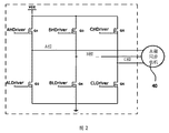
- FIG. 2 is a schematic diagram of a driving circuit of a three-phase permanent magnet synchronous motor according to an embodiment of the present application
- FIG. 3 is a schematic flow chart of a method for braking a permanent magnet synchronous motor according to an embodiment of the present application
- FIG. 4 is a schematic diagram of a rotational speed change of a plurality of permanent magnet synchronous motors after receiving a control signal according to an embodiment of the present application;
- FIG. 5 is a schematic flow chart of another permanent magnet synchronous motor braking method according to an embodiment of the present application.
- FIG. 6 is a unit composition diagram of a permanent magnet synchronous motor braking device provided by an embodiment of the present application.
- FIG. 7 is a schematic structural diagram of an electronic governor provided by an embodiment of the present application.
- the permanent magnet synchronous motor braking method, the electronic governor and the unmanned aerial vehicle implementing the permanent magnet synchronous motor braking method provided by the embodiments of the present application control the motor through two stages to realize connection with the controlled motor.
- the propeller stops rotating synchronously with the naked eye, thus ensuring consistent shutdown and improving the drone experience.
- the drone may include a drone body 20, a boom 21, a propeller 32-38, a permanent magnet synchronous motor, a flight controller, and an Electronic Speed Controller (ESC).
- a drone body 20 a drone body 20
- a boom 21 a propeller 32-38
- a permanent magnet synchronous motor a flight controller
- ESC Electronic Speed Controller
- the drone body 20 is connected to the arm 21 .
- Each of the arms 21 is provided with a permanent magnet synchronous motor, and each permanent magnet synchronous motor is connected to a propeller.
- a permanent magnet synchronous motor 40 is disposed on the arm 21, and a permanent magnet synchronous motor 40 is coupled to the propeller 36. After the permanent magnet synchronous motor rotates, the propeller can be driven to rotate to generate lift. It can be understood that the rotational speed of the propeller can generally be consistent with the rotational speed of the permanent magnet synchronous motor.
- the flight controller and the electronic governor are disposed in the UAV body 20 or the arm 21, which are not shown in the drawings.
- the flight controller is electrically connected to the electronic governor, and the electronic governor is electrically connected to the permanent magnet synchronous motor described above.
- the flight controller can send a flight signal or a brake signal to the electronic governor, and the electronic governor can control the rotational speed of the permanent magnet synchronous motor according to the signal sent by the flight controller. For example, a control signal or the like is sent to the motor.
- a specific implementation of the electronic governor to control the permanent magnet synchronous motor refer to the following method embodiments.
- the electronic governor can correspond to one or more permanent magnet synchronous motors. That is, the electronic governor can control the speed of a permanent magnet synchronous motor, for example, suppose the drone is equipped with 4 for driving the propeller
- the permanent magnet synchronous motor can be configured with four electronic governors, and each electronic governor corresponds to a permanent magnet synchronous motor.
- the electronic governor can simultaneously control the rotational speed of a plurality of permanent magnet synchronous motors, for example, assuming that the drone is provided with four permanent magnet synchronous motors for driving the propeller, the drone can be configured with an electronic governor
- the electronic governor is used to control the above four permanent magnet synchronous motors. This is not limited here.
- the drone may further include a gimbal 22.
- the pan/tilt head 22 can be connected to the camera for maintaining the stability of the camera and ensuring the stability of the image taken by the camera.
- the above-mentioned drone can also include a wireless communication interface, and the drone can realize wireless connection and communication with the remote controller 10 through a wireless communication interface.
- the communication interface of the drone receives the stop command sent by the remote controller, and the communication interface can send the stop command to the flight controller in the drone, and the aircraft can send the electronic governor to the electronic governor according to the stop command.
- the braking command of the magnetic synchronous motor so that the electronic governor adjusts the permanent magnet synchronous motor according to the braking command, that is, controls the permanent magnet synchronous motor to reduce the rotation speed.
- Step 301 The electronic governor receives a signal sent by the flight controller to brake the permanent magnet synchronous motor.
- the brake signal sent by the flight controller is used for synchronous braking of a plurality of, that is, at least two, permanent magnet synchronous motors. That is, the flight controller instructs a plurality of permanent magnet synchronous motors to achieve synchronous stop or propeller synchronous still in the case of visual observation.
- the brake signal can also be used to indicate a braking mode, ie different braking signals correspond to different braking modes.
- the electronic governor can determine the braking mode for the permanent magnet synchronous motor. Among them, the braking mode may include energy braking, regenerative braking, and the like. Furthermore, the electronic governor can determine different first control signals and second control signals according to different braking modes indicated by the braking signals.
- the brake signal can also be used to indicate whether to synchronize the braking of the plurality of permanent magnet synchronous motors. If the brake signal indicates that multiple permanent magnet synchronous motors can perform synchronous braking, steps can be performed 302. If the brake signal is not indicated, or the brake signal indicates that the plurality of permanent magnet synchronous motors are not synchronously braked, the electronic governor may stop supplying current to the permanent magnet synchronous motor, thereby causing the permanent magnet synchronous motor to gradually decrease based on inertia.
- the small speed, or the electronic governor provides a control signal to the permanent magnet synchronous motor, so that the braking torque is generated based on the control signal in the permanent magnet synchronous motor, and the permanent magnet synchronous motor gradually reduces the rotational speed under the action of the braking torque.
- the electronic governor In order to achieve the effect of controlling the permanent magnet motor brake by the electronic governor.
- Step 302 the electronic governor sends a first control signal to the permanent magnet synchronous motor, and the first control signal is used to control the permanent magnet synchronous motor to reduce the rotational speed to a preset in a first preset time period. Within the speed range.
- the electronic governor receives the brake signal, if the electronic governor controls two or more of the plurality of permanent magnet synchronous motors, the electronic governor is One or more permanent magnet synchronous motors simultaneously transmit the first control signal. Further, it is possible to control the rotational speeds of the two or more permanent magnet synchronous motors to decrease within a preset rotational speed range for the first predetermined time period. To achieve the first phase of synchronous braking of the motor.
- each of the electronic governors can send a first control signal to the permanent magnet synchronous motor controlled thereby at the same time, thereby The rotation speed of each of the permanent magnet synchronous motors can be controlled to be reduced to within the preset speed range within the first predetermined period of time.
- the moment may be preset or indicated by the flight controller, and is not limited herein.
- the first control signal may be a Pulse Width Modulation (PWM) signal or a Pulse Phase Modulation (PPM) signal, which is not limited herein.
- PWM Pulse Width Modulation
- PPM Pulse Phase Modulation
- the duty ratio of the first control signal may be determined by the first preset time period and the preset speed range. That is, the electronic governor can achieve the effect that the rotational speed of the permanent magnet synchronous motor is reduced to the preset rotational speed range within the first preset time period by determining the duty ratio of the first control signal.
- the duty ratio of the first control signal may be preset, and the electronic governor determines the first control signal by calling a preset duty cycle parameter.
- the duty ratio of the first control signal may be determined by the initial rotational speed of the permanent magnet synchronous motor before being controlled by the control signal, the first preset time period, and the first predetermined rotational speed range.
- the electronic governor detects the rotational speed of the permanent magnet synchronous motor, which can be understood as the initial rotational speed.
- the electronic governor is based on the initial rotational speed and according to the permanent magnet synchronous electric
- the first predetermined speed range to be reached by the machine during the first preset time period determines the duty ratio of the first control signal.
- the electronic governor can determine the duty cycle of the first control signal based on the actual rotational speed of the permanent magnet synchronous motor.
- Step 303 after the end of the first preset time period, the electronic governor sends a second control signal to the permanent magnet synchronous motor, where the second control signal is used to control the permanent magnet synchronous motor in the first The rotation is stopped within two preset time periods.
- the rotational speed of the permanent magnet synchronous motor is already within the first predetermined rotational speed range.
- the electronic governor can send a second control signal to the permanent magnet synchronous motor, and the second control signal can control the permanent magnet synchronous motor to stop rotating for the second predetermined time period.
- the braking torque generated based on the first control signal is less than the braking torque generated based on the second control signal.
- the permanent magnet synchronous motor can be stopped to rotate in a short time.
- stopping the rotation means that the rotational speed of the permanent magnet synchronous motor is 0 or the rotational speed is insufficient to drive the propeller.
- a plurality of permanent magnet synchronous motors are synchronously braked, that is, the propeller stops rotating at the same time.
- the duty cycle of the second control signal may be preset.
- the electronic governor may send the first control to the permanent magnet synchronous motor in the plurality of permanent magnet synchronous motors.
- the signal, the first control signal may be used to control the permanent magnet synchronous motor to decrease the rotational speed to a preset rotational speed range during the first predetermined time period.
- the electronic governor may further send a second control signal to the permanent magnet synchronous motor, and the second control signal may be used to control the permanent magnet synchronous motor to stop rotating in the second preset time period.
- FIG. 4 is a schematic diagram of a change in the rotational speed of a multi-permanent magnet synchronous motor after receiving a control signal according to an embodiment of the present application.
- the x-axis represents time and the y-axis represents the rotational speed of the permanent magnet synchronous motor.
- the curve A represents the rotational speed variation curve of the permanent magnet synchronous motor A
- the curve B represents the rotational speed variation curve of the permanent magnet synchronous motor B.
- a plurality of permanent magnet synchronous motors for driving the propeller may be included in the drone, and only two of the permanent magnet synchronous motors are taken as an example.
- the above two permanent magnet synchronous motors can be controlled by one electronic governor, or each controlled by A corresponding electronic governor is not limited here.
- the initial rotational speed of the permanent magnet synchronous motor A is different from the initial rotational speed of the permanent magnet synchronous motor B.
- the time period T1 from the time t1 to the time t2 is the first preset time period.
- the time period T2 from the time t2 to the time t3 is the second preset time period.
- the curve corresponding to the time period T1 in the curve A is the rotation speed drop curve of the permanent magnet synchronous motor A under the control of the first control signal.
- the right corresponding to the time period T1 in the curve B is the speed drop curve of the permanent magnet synchronous motor B under the control of the first control signal.
- the permanent magnet synchronous motor A and the permanent magnet synchronous motor B each generate a first braking torque based on the first control signal, causing the rotational speed to decrease.
- the action period of the first braking torque is the time period T1.
- the preset speed range is embodied in FIG. 4 as the range of speeds between the speeds RS1 and RS2.
- the permanent magnet synchronous motor A and the permanent magnet synchronous motor B are both controlled by the second control signal, and the second braking torque is generated based on the second control signal, causing it to stop rotating.
- the action period of the second braking torque is the time period T2.
- the second braking torque is greater than the first braking torque.
- FIG. 5 is a schematic flow chart of another permanent magnet synchronous motor braking method according to an embodiment of the present application. As shown in FIG. 5, the method includes at least the following steps.
- Step 501 The electronic governor receives a signal sent by the flight controller to brake the permanent magnet synchronous motor.
- Step 502 the electronic governor determines a braking mode for the permanent magnet synchronous motor.
- the braking mode may be indicated by the flight controller through the above-mentioned braking signal, or may be preset, and is not limited herein.
- the braking mode may include a power consumption braking, a reverse braking, a regenerative braking, and the like, which are not limited herein.
- Step 503 the electronic governor determines the first control signal and the second control signal corresponding to the braking mode.
- different braking modes may correspond to different first control signals and second control signals.
- the duty cycle of the control signal is proportional to the braking torque generated by the permanent magnet synchronous motor based on the control signal.
- the duty ratio of the first control signal is less than the second control
- the duty cycle of the signal is made such that the first braking torque of the permanent magnet synchronous motor is less than the second braking torque.
- the first braking torque is generated by the permanent magnet synchronous motor based on the first control signal
- the second braking torque is generated by the permanent magnet synchronous motor based on the second control signal.
- the duty cycle of the control signal is inversely proportional to the braking torque generated by the permanent magnet synchronous motor based on the control signal.
- the duty cycle of the first control signal is greater than the duty cycle of the second control signal.
- Step 504 the electronic governor sends a first control signal to the permanent magnet synchronous motor, where the first control signal is used to control the permanent magnet synchronous motor to reduce the rotational speed to a preset in a first preset time period. Within the speed range.
- Step 505 the electronic governor sends a second control signal to the permanent magnet synchronous motor after the end of the first preset period, where the second control signal is used to control the permanent magnet synchronous motor The rotation is stopped within two preset time periods.
- FIG. 2 is a schematic diagram of a driving circuit of a permanent magnet synchronous motor.
- the drive circuit can be a three-phase full bridge circuit.
- the first control signal and the second control signal are controlled to control the permanent magnet synchronous motor to generate a braking torque by controlling one or more of the drive switches Q1 to Q6 to be closed.
- AHDriver, ALDriver, BHDriver, BLDriver, CHDriver, CLDriver are the control signal input terminals in the above drive switches.
- the first control signal can be input to the ALDriver, BLDriver, and CLDriver terminals, respectively.
- the drive switches Q1, Q3, Q5 are turned off. Therefore, under the driving of the first control signal, the driving switches Q2, Q4, and Q6 are simultaneously turned on and off, and the three phases of the permanent magnet synchronous motor A, B, and C are short-circuited when the conduction is performed, so that the stator winding of the motor forms a current.
- the circuit generates a braking current driven by the back electromotive force of the winding, thereby generating a first braking torque that prevents the rotor connecting the propeller from rotating.
- the action period of the first control signal is a first preset time period.
- the second control signal can cause the permanent magnet synchronous motor to generate the second braking torque by two different modes of action.
- the second control signal can be used to control the three-phase short circuit of the permanent magnet synchronous motor. as shown in picture 2,
- the duty ratio of the second control signal may be 100%, or the duty ratio of the second control signal may be It is set to enable the three phases A, B, and C of the permanent magnet synchronous motor to be short-circuited in the second predetermined period of time. That is, the control drive switches Q2, Q4, and Q6 are turned on for the second predetermined period of time. In this case, the permanent magnet synchronous motor generates a second braking torque according to the energy consumption therein, so that the permanent magnet synchronous motor can stop rotating under the action of the second braking torque.
- the second control signal can be used to control the three-phase input of the permanent magnet synchronous motor to have a braking current, and the permanent magnet synchronous motor generates a second braking torque under the action of the braking current, thereby enabling the permanent magnet synchronous motor The rotation is stopped under the action of the second braking torque.
- the electronic governor can determine the first control signal and the second control signal corresponding to the braking mode based on different braking modes. Thereby, the control mode of the electronic governor can be made more flexible.
- FIG. 6 is a block diagram of a permanent magnet synchronous motor braking device according to an embodiment of the present application.
- the permanent magnet synchronous braking device 600 may include an input unit 601, a processing unit 603, and an output unit 605.
- the input unit 601 is configured to receive a signal sent by the flight controller to brake the permanent magnet synchronous motor
- the output unit 605 is configured to send a first control signal to the permanent magnet synchronous motor, where the first control signal is used to control the permanent magnet synchronous motor to decrease the rotational speed to a preset rotational speed range within a first preset time period. ;
- the output unit 605 is further configured to send a second control signal to the permanent magnet synchronous motor after the end of the first preset time period, where the second control signal is used to control the permanent magnet synchronous motor The rotation is stopped within two preset time periods.
- processing unit 603 is configured to:
- the first control signal and the second control signal corresponding to the braking mode are determined.
- the functions of the above functional units may be implemented by a specific hardware structure of the electronic governor, or a computer instruction stored in the storage, or a combination of the two, and are not limited herein.
- FIG. 7 is a schematic structural diagram of an electronic governor according to an embodiment of the present application.
- the electronic governor 700 can include a memory 701, a processor 703, and a communication interface 705.
- the processor 703 is coupled to the memory 705 and the memory 705, respectively.
- the memory 703 is configured to store program code, computer instructions, and data; the processor 703 is configured to invoke computer instructions and data to perform any of the methods performed by the electronic governor described above; the communication interface 705 is used under the control of the processor 703 Signal interaction with a flight controller or permanent magnet synchronous motor.
- the processor 703 may also include a Central Processing Unit (CPU). Alternatively, processor 703 can also be understood to be a controller.
- CPU Central Processing Unit
- processor 703 can also be understood to be a controller.
- the storage unit 701 may include a read only memory and a random access memory, and supplies instructions and data and the like to the processor 703. A portion of the storage unit 701 may also include a non-volatile random access memory.
- the components of a particular application are coupled together, for example, via a bus system.
- the bus system can also include a power bus, a control bus, and a status signal bus.
- various buses are labeled as bus system 707 in the figure.
- Processor 703 may be an integrated circuit chip with signal processing capabilities. In the implementation process, each step of the foregoing method may be completed by an integrated logic circuit of hardware in the processor 703 or an instruction in a form of software.
- the processor 703 may be a general purpose processor, a digital signal processor, an application specific integrated circuit, an off-the-shelf programmable gate array or other programmable logic device, a discrete gate or transistor logic device, or a discrete hardware component.
- the processor 703 can implement or perform the various methods, steps, and logic blocks disclosed in the embodiments of the present invention.
- the processor 703 can be an image processor, a microprocessor, or the processor can be any conventional processor or the like.
- the steps of the method disclosed in the embodiments of the present invention may be directly implemented by the hardware decoding processor, or may be performed by a combination of hardware and software modules in the decoding processor.
- the software module can be located in a conventional storage medium such as random access memory, flash memory, read only memory, programmable read only memory or electrically erasable programmable memory, registers, and the like.
- the storage medium is located in the storage unit 701.
- the processor 703 can read the program code, computer instructions or data in the storage unit 701, and complete the steps of the above method performed by the electronic governor in combination with the hardware thereof.
Landscapes
- Engineering & Computer Science (AREA)
- Power Engineering (AREA)
- Aviation & Aerospace Engineering (AREA)
- Control Of Multiple Motors (AREA)
- Control Of Eletrric Generators (AREA)
- Stopping Of Electric Motors (AREA)
Abstract
一种永磁同步电机制动方法及相关设备,该方法应用于电子调速器上,包括:接收飞行控制器发送的对永磁同步电机进行制动的信号;向所述永磁同步电机发送第一控制信号,所述第一控制信号用于控制所述永磁同步电机在第一预设时段内减小转速至预设转速范围内;在所述第一预设时段结束后,向所述永磁同步电机发送第二控制信号,所述第二控制信号用于控制所述永磁同步电机在第二预设时段内停止转动。通过上述方法,保证了多电机停机的一致性,并提升了无人机使用体验。
Description
本申请要求于2016年11月18日提交中国专利局、申请号为201611041815.X、申请名称为“一种永磁同步电机制动方法及相关设备”的中国专利申请的优先权,其全部内容通过引用结合在本申请中。
本申请涉及无人机领域,特别是涉及一种永磁同步电机制动方法及相关设备。
当前,无人飞行器(Unmanned Aerial Vehicle,UAV),可以简称为无人机,通过控制多个电机的转速,使与多个电机各自连接的螺旋桨产生升力,以实现飞行。当无人机停机后,电源关闭,多个电机的转速基于惯性逐渐减小,其进而致使多个电机各自所连接的螺旋桨逐渐停止转动。
在此种情况下,由于各个电机所处的位置不同,与各个电机连接的螺旋桨所处的位置也不同,其所受空气流动阻力以及其他譬如摩擦阻力的大小有差异,从而无法保证多个螺旋桨在肉眼观察的情况下同步停止转动,一般情况下各螺旋桨会先后停止转动,降低了无人机使用的体验。
同时,在上述情况下,由于各个电机在停止转动的过程不一致,导致长期使用后各个电机的磨损差异会增大,存在破坏无人飞行器飞行平衡的风险。
发明内容
本发明实施方式提供了一种永磁同步电机制动方法及相关设备。保证了多电机停机的一致性,并提升了无人机使用体验。
第一方面,本申请实施例提供了一种永磁同步电机制动方法,该方法可以包括:
接收飞行控制器发送的对永磁同步电机进行制动的信号;向所述永磁同步电机发送第一控制信号,所述第一控制信号用于控制所述永磁同步电机在第一预设时段内减小转速至预设转速范围内;在所述第一预设时段结束后,向所述永磁同步电机发送第二控制信号,所述第二控制信号用于控制所述永磁同步电机在第二预设时段内停止转动。
第二方面,本申请实施例提供了一种永磁同步电机制动装置,该装置包括功能单元,该功能单元用于执行第一方面中的方法。
第三方面,本申请实施例提供了一种电子调速器,包括:
存储器;以及
与所述存储器耦合的处理器;
其中,所述存储器用于存储计算机指令;
所述处理器用于调用所述计算机指令,以执行第一方面中的方法。
第四方面,本申请实施例提供了一种无人机,包括:
中心机壳;
机臂,所述机臂与所述中心机壳连接;
永磁同步电机,所述永磁同步电机设置在所述机臂上;
飞行控制器,所述飞行控制器设置在所述中心机壳或所述机臂内;以及,
电子调速器,所述电子调速器设置在所述中心机壳或所述机臂内,所述电子调速器与所述飞行控制器电连接,所述电子调速器与所述永磁同步电机电连接;
其中,所述飞行控制器用于向所述电子调速器发送对所述永磁同步电机的制动信号;
所述电子调速器用于执行第一方面中的方法。
第五方面,本申请实施例提供了一种计算机可读存储介质,该计算机可读存储介质存储有计算机指令,该计算机指令用于被电子调速器调用以执行第一方面中的方法。
本申请实施例中,电子调速器在接收到飞行控制器发送的对多个永磁同步电机的制动信号后,可以向该多个永磁同步电机中的永磁同步电机发送第一控制信号,该第一控制信号可以用于控制永磁同步电机在第一预设时段内减小转速至预设转速范围。在第一预设时段结束后,该电子调速器还可以向永磁同步电机发送第二控制信号,该第二控制信号可以用于控制该永磁同步电机在第二预设时段内停止转动。通过上述方式,可以保证了多电机停机的一致性。
图1是本申请实施例提供的一种无人机的结构示意图;
图2是本申请实施例提供的一种三相永磁同步电机的驱动电路的示意图;
图3是本申请实施例提供的一种永磁同步电机制动方法的流程示意图;
图4是本申请实施例提供的一种多个永磁同步电机接收到控制信号后的转速变化示意图;
图5是本申请实施例提供的另一种永磁同步电机制动方法的流程示意图;
图6是本申请实施例提供的一种永磁同步电机制动装置的单元组成图;以及
图7是本申请实施例提供的一种电子调速器的结构示意图。
本申请实施例提供的永磁同步电机制动方法、电子调速器和实现永磁同步电机制动方法的无人机,通过两个阶段对电机进行控制,以实现与所控制的电机连接的螺旋桨在肉眼观察的情况下同步停止转动,从而保证了停机的一致性,并提升了无人机使用体验。
下面结合附图对本申请实施例进行说明。
首先结合图1和图3,对本申请实施例提供的一种无人机的结构组成进行说明。如图1中所示,该无人机可以包括无人机机身20、机臂21、螺旋桨32-38,永磁同步电机,飞行控制器以及电子调速器(Electronic Speed Controller,ESC)。
其中,无人机机身20与机臂21连接。每个机臂21上设置有一个永磁同步电机,每个永磁同步电机与一个螺旋桨连接。例如,如图1所示,机臂21上设置有永磁同步电机40,永磁同步电机40与螺旋桨36连接。永磁同步电机转动后,可以驱动螺旋桨旋转,以使螺旋桨产生升力。可以理解地,通常螺旋桨的转速可以与永磁同步电机的转速保持一致。
其中,飞行控制器以及电子调速器设置在无人机机身20或机臂21内,在图中并未示出。飞行控制器与电子调速器电连接,并且电子调速器与上述永磁同步电机电连接。飞行控制器可以向电子调速器发送飞行信号或制动信号,电子调速器可以根据飞行控制器发送的信号,来控制永磁同步电机的转速。例如,向电机发送控制信号等。电子调速器控制永磁同步电机的具体实现方式可以参见下述方法实施例。
其中,电子调速器可以对应一个或多个永磁同步电机。即电子调速器可以控制一个永磁同步电机的转速,例如,假设无人机设置有4个用于驱动螺旋桨
的永磁同步电机,该无人机可以配置有四个电子调速器,每个电子调速器分别对应一个永磁同步电机。或者,电子调速器可以同时控制多个永磁同步电机的转速,例如,假设无人机设置有4个用于驱动螺旋桨的永磁同步电机,该无人机可以配置有一个电子调速器,该电子调速器用于控制上述4个永磁同步电机。在此不予限定。
可选地,该无人机还可以包括云台22。云台22可以与相机连接,用于对相机进行维稳,保证相机拍摄图像的稳定性。
上述无人机还可以包括无线通信接口,无人机可以通过无线通信接口实现与遥控器10的无线连接及通信。
例如,无人机的通信接口接收到遥控器发送的停机指令,该通信接口可以将停机指令发送给无人机中的飞行控制器,飞行器可以根据该停机指令,向电子调速器发送对永磁同步电机的制动指令,从而使电子调速器根据制动指令对永磁同步电机进行调速,即控制永磁同步电机减小转速。
需要说明的是,图1中所示无人机的形状及各部件的位置仅为示例性地,在此不予限定。
下面结合上述无人机结构,对本申请实施例中的方法实施例进行说明。
步骤301,电子调速器接收飞行控制器发送的对永磁同步电机进行制动的信号。
其中,飞行控制器发送的制动信号用于对多个,即至少2个,永磁同步电机进行同步制动。即飞行控制器指示多个永磁同步电机在肉眼观察的情况下,可以实现同步停机或螺旋桨同步静止。
可选地,制动信号还可以用于指示制动模式,即不同的制动信号对应不同的制动模式。电子调速器在接收到制动信号后,即可确定对永磁同步电机的制动模式。其中,制动模式可以包括能耗制动、再生制动等。进而,电子调速器可以根据制动信号所指示的不同制动模式,确定不同的第一控制信号和第二控制信号。
可选地,制动信号还可以用于指示是否对多个永磁同步电机进行同步制动。若制动信号指示多个永磁同步电机可以进行同步制动,则可以执行步骤
302。若制动信号未指示,或制动信号指示多个永磁同步电机不进行同步制动,则电子调速器可以停止向永磁同步电机提供电流,进而致使该永磁同步电机基于惯性逐渐减小转速,或者,电子调速器向永磁同步电机提供控制信号,使永磁同步电机内基于该控制信号产生制动力矩,在制动力矩的作用下,永磁同步电机逐渐减小转速,以达到通过电子调速器控制永磁电机制动的效果。
步骤302,所述电子调速器向所述永磁同步电机发送第一控制信号,所述第一控制信号用于控制所述永磁同步电机在第一预设时段内减小转速至预设转速范围内。
示例性地,电子调速器在接收到制动信号后,若该电子调速器控制上述多个永磁同步电机中的2个或以上永磁同步电机时,该电子调速器向该2个或以上永磁同步电机同时发送第一控制信号。进而,可以控制这2个或以上永磁同步电机的转速在第一预设时段内减小至预设转速范围内。以实现电机同步制动的第一个阶段。若每个电子调速器各控制多个永磁同步电机中的一个永磁同步电机,则每个电子调速器可以在同一时刻向其所控制的永磁同步电机发送第一控制信号,从而可以控制各永磁同步电机的转速在第一预设时段内减小至预设转速范围内。其中,该时刻可以是预设的,或者是飞行控制器所指示的,在此不予限定。
示例性地,第一控制信号可以是脉冲宽度调制(Pulse Width Modulation,PWM)信号,或是脉冲相位调制(Pulse Phase Modulation,PPM)信号等,在此不予限定。
可选地,第一控制信号的占空比可以由第一预设时段及预设转速范围确定。即电子调速器可以通过确定第一控制信号的占空比,达到永磁同步电机的转速在第一预设时段内减小至预设转速范围内的效果。在此种情况下,第一控制信号的占空比可以是预设的,电子调速器通过调用预设的占空比参数,来确定第一控制信号。
或者,第一控制信号的占空比可以由永磁同步电机在受上述控制信号控制之前的初始转速、第一预设时段和第一预设转速范围确定的。具体地,电子调速器在接收到飞行控制器发送的制动信号后,检测永磁同步电机的转速,该转速可以理解为是初始转速。电子调速器根据该初始转速,并根据该永磁同步电
机在第一预设时段所要达到的第一预设转速范围,确定第一控制信号的占空比。在此种情况下,电子调速器可以根据永磁同步电机的实际转速确定第一控制信号的占空比。
步骤303,在所述第一预设时段结束后,所述电子调速器向所述永磁同步电机发送第二控制信号,所述第二控制信号用于控制所述永磁同步电机在第二预设时段内停止转动。
示例性地,在第一预设时段结束后,永磁同步电机的转速已在第一预设转速范围内。进而,电子调速器可以向该永磁同步电机发送第二控制信号,该第二控制信号可以控制永磁同步电机在第二预设时段内停止转动。
其中,在永磁同步电机中,基于第一控制信号所产生的制动力矩小于基于第二控制信号所产生的制动力矩。基于第二控制信号所产生的制动力矩可以实现永磁同步电机在短时间内停止转动。在此,停止转动是指永磁同步电机的转速为0或者转速不足以驱动螺旋桨。进而实现了在肉眼观察的情况下,多个永磁同步电机同步制动,即螺旋桨同时停止转动的效果。
示例性地,该第二控制信号的占空比可以是预设的。
本申请实施例中,电子调速器在接收到飞行控制器发送的对多个永磁同步电机的制动信号后,可以向该多个永磁同步电机中的永磁同步电机发送第一控制信号,该第一控制信号可以用于控制永磁同步电机在第一预设时段内减小转速至预设转速范围。在第一预设时段结束后,该电子调速器还可以向永磁同步电机发送第二控制信号,该第二控制信号可以用于控制该永磁同步电机在第二预设时段内停止转动。通过上述方式,可以保证了多电机停机的一致性,进而避免多电机的不同损耗,保证了无人机的飞行平衡,并提升了无人机使用体验。
下面结合图4,对上述实现方式进行说明。图4是本申请实施例提供的一种多永磁同步电机接收到控制信号后的转速变化示意图。
如图4所示,x轴代表时间,y轴代表永磁同步电机的转速。其中,曲线A代表永磁同步电机A的转速变化曲线,曲线B代表永磁同步电机B的转速变化曲线。当然,无人机中可以包括多个用于驱动螺旋桨的永磁同步电机,在此仅以其中的2个永磁同步电机为例进行说明。
其中,上述2个永磁同步电机可以受控于一个电子调速器,或各自受控于
一个对应的电子调速器,在此不予限定。
图4所示,在初始时刻t1,永磁同步电机A的初始转速与永磁同步电机B的初始转速不同。其中,时刻t1至时刻t2的时段T1即为第一预设时段。时刻t2至时刻t3的时段T2即为第二预设时段。曲线A中时段T1对应的曲线即为永磁同步电机A在第一控制信号控制下的转速下降曲线。同理,曲线B中时段T1对应的权限即为永磁同步电机B在第一控制信号控制下转速下降曲线。在时段T1内,永磁同步电机A及永磁同步电机B均基于第一控制信号产生第一制动力矩,致使其转速下降。其中,该第一制动力矩的作用时段即为时段T1。在第一控制信号的作用下,曲线A与曲线B中在t2时刻对应的转速均已落入预设转速范围内。该预设转速范围在图4中体现为转速RS1至转速RS2之间的转速范围。从时刻t2开始,永磁同步电机A及永磁同步电机B均受控于第二控制信号,基于第二控制信号产生第二制动力矩,致使其停止转动。其中,第二制动力矩的作用时段即为时段T2。其中,第二制动力矩大于第一制动力矩。通过上述方式,如图所示,可以使永磁同步电机A和永磁同步电机B几乎在同一时刻下,停止转动。进而,通过两个阶段的控制信号,可以实现多电机同步停机。
请参阅图5,图5是本申请实施例提供的另一个永磁同步电机制动方法的流程示意图。如图5所示,该方法至少包括以下步骤。
步骤501,电子调速器接收飞行控制器发送的对永磁同步电机进行制动的信号。
步骤502,所述电子调速器确定对所述永磁同步电机的制动模式。
示例性地,该制动模式可以是飞行控制器通过上述制动信号所指示的,或者是预设的,在此不予限定。其中,制动模式可以包括能耗制动、反接制动、再生制动等,在此不予限定。
步骤503,所述电子调速器确定与所述制动模式对应的所述第一控制信号和第二控制信号。
示例性地,不同的制动模式可对应不同的第一控制信号和第二控制信号。
例如,在能耗制动模式下,控制信号的占空比与永磁同步电机基于控制信号生成的制动力矩成正比。在此种情况下,第一控制信号的占空比小于第二控
制信号的占空比;从而使永磁同步电机的第一制动力矩小于第二制动力矩。其中,第一制动力矩是永磁同步电机基于第一控制信号产生的,第二制动力矩是永磁同步电机基于第二控制信号产生的。
或者,在再生制动模式下,控制信号的占空比与永磁同步电机基于控制信号生成的制动力矩成反比。在此种情况下,第一控制信号的占空比大于第二控制信号的占空比。
步骤504,所述电子调速器向所述永磁同步电机发送第一控制信号,所述第一控制信号用于控制所述永磁同步电机在第一预设时段内减小转速至预设转速范围内。
步骤505,所述电子调速器在所述第一预设时段结束后,向所述永磁同步电机发送第二控制信号,所述第二控制信号用于控制所述永磁同步电机在第二预设时段内停止转动。
下面结合图2对永磁同步电机基于控制信号生成制动力矩的具体实现方式进行说明。
请参阅图2,图2示出了一种永磁同步电机的驱动电路的示意图。该驱动电路可以是三相全桥电路。第一控制信号与第二控制信号通过控制驱动电路中驱动开关Q1至Q6中的一个或多个开关闭合,来控制永磁同步电机产生制动力矩。其中,AHDriver,ALDriver,BHDriver,BLDriver,CHDriver,CLDriver分别是上述驱动开关中的控制信号输入端。
电子调速器向永磁同步电机发送第一控制信号时,可以将第一控制信号分别输入至ALDriver,BLDriver,CLDriver端。同时,驱动开关Q1,Q3,Q5关闭。由此,在第一控制信号的驱动下,驱动开关Q2,Q4,Q6同时导通关闭,导通时将永磁同步电机的A、B、C三相短接,使电机的定子绕组形成电流回路,在绕组的反电动势驱动下产生制动电流,从而产生第一制动力矩,阻止连接螺旋桨的转子转动。其中,第一控制信号的作用时段为第一预设时段。
在第一预设时段结束后,第二控制信号通过两种不同的作用方式,均可使永磁同步电机生成第二制动力矩。
方式一,第二控制信号可用于控制永磁同步电机的三相短接。如图2所示,
第二控制信号的占空比可以为100%,或者,第二控制信号的占空比可以
设置为能够使永磁同步电机的A、B、C三相在第二预设时段内短接。即控制驱动开关Q2,Q4,Q6在第二预设时段内导通。在此情况下,永磁同步电机根据其内的能耗产生第二制动力矩,进而可以使永磁同步电机在第二制动力矩的作用下停止转动。
方式二,第二控制信号可用于控制永磁同步电机的三相输入有制动电流,永磁同步电机在该制动电流的作用下,产生第二制动力矩,进而可以使永磁同步电机在第二制动力矩的作用下停止转动。
通过上述方式,电子调速器可以基于不同的制动模式,确定与制动模式对应的第一控制信号和第二控制信号。从而,可以使电子调速器的控制方式更加灵活。
请参阅图6,图6是本申请实施例提供的一种永磁同步电机制动装置的单元组成图。如图6所示,该永磁同步制动装置600可以包括输入单元601、处理单元603及输出单元605。
其中,输入单元601,用于接收飞行控制器发送的对永磁同步电机进行制动的信号;
输出单元605,用于向所述永磁同步电机发送第一控制信号,所述第一控制信号用于控制所述永磁同步电机在第一预设时段内减小转速至预设转速范围内;
所述输出单元605,还用于在所述第一预设时段结束后,向所述永磁同步电机发送第二控制信号,所述第二控制信号用于控制所述永磁同步电机在第二预设时段内停止转动。
可选地,处理单元603用于:
确定对所述永磁同步电机的制动模式;
确定与所述制动模式对应的所述第一控制信号和第二控制信号。
当然,上述功能单元还用于执行上述实施例中电子调速器所执行的任意一种方法,在此不予赘述。
上述功能单元的功能可由电子调速器的具体硬件结构、或存储中中存储的计算机指令、或二者结合实现,在此不予限定。
请参阅图7,图7是本申请实施例提供的一种电子调速器的结构示意图。
如图7所示,电子调速器700可以包括存储器701、处理器703和通信接口705。其中,处理器703分别和存储器701与通信接口705耦合。
存储器703用于存储程序代码、计算机指令和数据;处理器703用于调用计算机指令和数据以执行上述电子调速器所执行的任意一种方法;通信接口705用于在处理器703的控制下与飞行控制器或永磁同步电机进行信号交互。
处理器703还可以包括中央处理单元(CPU,Central Processing Unit)。或者,处理器703也可以理解为是控制器。
存储单元701可以包括只读存储器和随机存取存储器,并向处理器703提供指令和数据等。存储单元701的一部分还可包括非易失性随机存取存储器。具体的应用中各组件例如通过总线系统耦合在一起。总线系统除了可包括数据总线之外,还可以包括电源总线、控制总线和状态信号总线等。但是为了清楚说明起见,在图中将各种总线都标为总线系统707。
上述本发明实施例揭示的方法可由处理器703实现。处理器703可能是一种集成电路芯片,具有信号的处理能力。在实现过程中,上述方法的各步骤可以通过处理器703中的硬件的集成逻辑电路或者软件形式的指令完成。其中,上述处理器703可以是通用处理器、数字信号处理器、专用集成电路、现成可编程门阵列或者其他可编程逻辑器件、分立门或者晶体管逻辑器件、分立硬件组件。处理器703可以实现或者执行本发明实施例中的公开的各方法、步骤及逻辑框图。处理器703可以是图像处理器、微处理器或者该处理器也可以是任何常规的处理器等。结合本发明实施例所公开的方法的步骤可以直接体现为硬件译码处理器执行完成,或者用译码处理器中的硬件及软件模块组合执行完成。软件模块可以位于随机存储器,闪存、只读存储器,可编程只读存储器或者电可擦写可编程存储器、寄存器等本领域成熟的存储介质中。该存储介质位于存储单元701,例如处理器703可读取存储单元701中的程序代码、计算机指令或数据,结合其硬件完成电子调速器所执行的上述方法的步骤。
以上所述仅为本发明的实施方式,并非因此限制本发明的专利范围,凡是利用本发明说明书及附图内容所作的等效结构或等效流程变换,或直接或间接运用在其他相关的技术领域,均同理包括在本发明的专利保护范围内。
Claims (22)
- 一种永磁同步电机制动方法,所述方法应用于电子调速器上,其特征在于,包括:接收飞行控制器发送的对永磁同步电机进行制动的信号;向所述永磁同步电机发送第一控制信号,所述第一控制信号用于控制所述永磁同步电机在第一预设时段内减小转速至预设转速范围内;在所述第一预设时段结束后,向所述永磁同步电机发送第二控制信号,所述第二控制信号用于控制所述永磁同步电机在第二预设时段内停止转动。
- 根据权利要求1所述方法,其特征在于,所述方法还包括:确定对所述永磁同步电机的制动模式;确定与所述制动模式对应的所述第一控制信号和第二控制信号。
- 根据权利要求2所述方法,其特征在于,若所述制动模式为能耗制动,所述第一控制信号的占空比小于所述第二控制信号的占空比;若所述制动模式为再生制动,所述第一控制信号的占空比大于所述第二控制信号的占空比。
- 根据权利要求1-3任一项所述方法,其特征在于,所述第一控制信号的占空比是根据所述第一预设时段以及所述预设转速范围确定的;或者,所述第一控制信号的占空比是根据所述永磁同步电机的初始转速、所述第一预设时段和所述第一预设转速范围确定的。
- 根据权利要求1-4任一项所述方法,其特征在于,所述第二控制信号用于控制所述永磁同步电机的三相短接,以控制所述永磁同步电机在所述第二预设时段内停止转动;或者,所述第二控制信号用于控制所述永磁同步电机的三相输入有制动电流,以控制所述永磁同步电机在所述第二预设时段内停止转动。
- 根据权利要求1-5任一项所述方法,其特征在于,所述永磁同步电机为至少2个,则所述接收所述飞行控制器发送的对所述永磁同步电机进行制动 的信号,包括:接收所述飞行控制器发送的对所述至少2个永磁同步电机进行制动的信号;所述向所述永磁同步电机发送所述第一控制信号,包括:向所述至少2个永磁同步电机中的至少1个永磁同步电机发送所述第一控制信号。
- 根据权利要求6所述方法,其特征在于,所述电子调速器用于控制至少1个永磁同步电机;则,所述向所述至少2个永磁同步电机中的至少1个永磁同步电机发送所述第一控制信号,包括:向所述电子调速器所控制的所述至少1个永磁同步电机发送所述第一控制信号。
- 一种永磁同步电机制动装置,其特征在于,包括:输入单元,用于接收飞行控制器发送的对永磁同步电机进行制动的信号;输出单元,用于向所述永磁同步电机发送第一控制信号,所述第一控制信号用于控制所述永磁同步电机在第一预设时段内减小转速至预设转速范围内;所述输出单元,还用于在所述第一预设时段结束后,向所述永磁同步电机发送第二控制信号,所述第二控制信号用于控制所述永磁同步电机在第二预设时段内停止转动。
- 根据权利要求8所述装置,其特征在于,还包括处理单元,所述处理单元用于:确定对所述永磁同步电机的制动模式;确定与所述制动模式对应的所述第一控制信号和第二控制信号。
- 根据权利要求9所述装置,其特征在于,若所述制动模式为能耗制动,所述第一控制信号的占空比小于所述第二控制信号的占空比;若所述制动模式为再生制动,所述第一控制信号的占空比大于所述第二控制信号的占空比。
- 根据权利要求8-10任一项所述装置,其特征在于,所述第一控制信号的占空比是根据所述第一预设时段以及所述预设转速范围确定的;或者,所述第一控制信号的占空比是根据所述永磁同步电机的初始转速、所述第一预设时段和所述第一预设转速范围确定的。
- 根据权利要求8-11任一项所述装置,其特征在于,所述第二控制信号用于控制所述永磁同步电机的三相短接,以控制所述永磁同步电机在所述第二预设时段内停止转动;或者,所述第二控制信号用于控制所述永磁同步电机的三相输入有制动电流,以控制所述永磁同步电机在所述第二预设时段内停止转动。
- 根据权利要求8-12任一项所述装置,其特征在于,所述永磁同步电机为至少2个,则所述输入单元用于:接收所述飞行控制器发送的对所述至少2个永磁同步电机进行制动的信号;所述向所述永磁同步电机发送所述第一控制信号,包括:向所述至少2个永磁同步电机中的至少1个永磁同步电机发送所述第一控制信号。
- 根据权利要求13所述装置,其特征在于,所述电子调速器控制至少1个永磁同步电机,则所述输入单元用于:向所述电子调速器所控制的所述至少1个永磁同步电机发送所述第一控制信号。
- 一种电子调速器,其特征在于,包括:存储器;以及与所述存储器耦合的处理器;其中,所述存储器用于存储计算机指令;所述处理器用于调用所述计算机指令,以执行以下方法:接收飞行控制器发送的对多个永磁同步电机的制动信号;向所述多个永磁同步电机中的永磁同步电机发送第一控制信号,所述第一 控制信号用于控制所述永磁同步电机在第一预设时段内减小转速至预设转速范围内;在所述第一预设时段结束后,向所述永磁同步电机发送第二控制信号,所述第二控制信号用于控制所述永磁同步电机在第二预设时段内停止转动。
- 根据权利要求15所述的电子调速器,其特征在于,所述处理器还用于调用所述计算机指令,以执行以下方法:确定对所述永磁同步电机的制动模式;确定与所述制动模式对应的所述第一控制信号和第二控制信号。
- 根据权利要求16所述的电子调速器,其特征在于:若所述制动模式为能耗制动,所述第一控制信号的占空比小于所述第二控制信号的占空比;若所述制动模式为再生制动,所述第一控制信号的占空比大于所述第二控制信号的占空比。
- 根据权利要求15-17任一项所述的电子调速器,其特征在于:所述第一控制信号的占空比是根据所述第一预设时段以及所述预设转速范围确定的;或者,所述第一控制信号的占空比是根据所述永磁同步电机的初始转速、所述第一预设时段和所述第一预设转速范围确定的。
- 根据权利要求15-18任一项所述的电子调速器,其特征在于,所述第二控制信号用于控制所述永磁同步电机的三相短接,以控制所述永磁同步电机在所述第二预设时段内停止转动;或者,所述第二控制信号用于控制所述永磁同步电机的三相输入有制动电流,以控制所述永磁同步电机在所述第二预设时段内停止转动。
- 根据权利要求15-19任一项所述的电子调速器,其特征在于,所述永磁同步电机为至少2个,则所述处理器执行所述接收所述飞行控制器发送的对所述永磁同步电机进行制动的信号,包括:接收所述飞行控制器发送的对所述至少2个永磁同步电机进行制动的信号;所述向所述永磁同步电机发送所述第一控制信号,包括:向所述至少2个永磁同步电机中的至少1个永磁同步电机发送所述第一控制信号。
- 根据权利要求20所述的电子调速器,其特征在于,所述电子调速器控制至少1个永磁同步电机,则所述处理器执行所述向所述至少2个永磁同步电机中的至少1个永磁同步电机发送所述第一控制信号,包括:向所述电子调速器所控制的所述至少1个永磁同步电机发送所述第一控制信号。
- 一种无人机,其特征在于,包括:中心机壳;机臂,所述机臂与所述中心机壳连接;永磁同步电机,所述永磁同步电机设置在所述机臂上;飞行控制器,所述飞行控制器设置在所述中心机壳或所述机臂内;以及,电子调速器,所述电子调速器设置在所述中心机壳或所述机臂内,所述电子调速器与所述飞行控制器电连接,所述电子调速器与所述永磁同步电机电连接;其中,所述飞行控制器用于向所述电子调速器发送对所述永磁同步电机的制动信号;所述电子调速器用于执行如权利要求1-7任一项所述方法。
Priority Applications (1)
| Application Number | Priority Date | Filing Date | Title |
|---|---|---|---|
| US16/415,470 US11581831B2 (en) | 2016-11-18 | 2019-05-17 | Method for braking permanent magnet synchronous motor and related device |
Applications Claiming Priority (2)
| Application Number | Priority Date | Filing Date | Title |
|---|---|---|---|
| CN201611041815.X | 2016-11-18 | ||
| CN201611041815.XA CN106655921A (zh) | 2016-11-18 | 2016-11-18 | 一种永磁同步电机制动方法及相关设备 |
Related Child Applications (1)
| Application Number | Title | Priority Date | Filing Date |
|---|---|---|---|
| US16/415,470 Continuation US11581831B2 (en) | 2016-11-18 | 2019-05-17 | Method for braking permanent magnet synchronous motor and related device |
Publications (1)
| Publication Number | Publication Date |
|---|---|
| WO2018090981A1 true WO2018090981A1 (zh) | 2018-05-24 |
Family
ID=58811591
Family Applications (1)
| Application Number | Title | Priority Date | Filing Date |
|---|---|---|---|
| PCT/CN2017/111681 Ceased WO2018090981A1 (zh) | 2016-11-18 | 2017-11-17 | 一种永磁同步电机制动方法及相关设备 |
Country Status (3)
| Country | Link |
|---|---|
| US (1) | US11581831B2 (zh) |
| CN (1) | CN106655921A (zh) |
| WO (1) | WO2018090981A1 (zh) |
Cited By (1)
| Publication number | Priority date | Publication date | Assignee | Title |
|---|---|---|---|---|
| EP3611837A1 (en) * | 2018-08-17 | 2020-02-19 | Goodrich Actuation Systems Limited | Electric motor |
Families Citing this family (8)
| Publication number | Priority date | Publication date | Assignee | Title |
|---|---|---|---|---|
| CN106655921A (zh) | 2016-11-18 | 2017-05-10 | 深圳市道通智能航空技术有限公司 | 一种永磁同步电机制动方法及相关设备 |
| CN110365255B (zh) * | 2019-07-24 | 2021-04-09 | 江西盈克电子科技有限公司 | 一种变频器的制动方法及系统 |
| CN112448620A (zh) * | 2019-09-02 | 2021-03-05 | 深圳拓邦股份有限公司 | 电机刹车控制方法、装置及电动工具 |
| US12074553B2 (en) * | 2019-10-23 | 2024-08-27 | Schlumberger Technology Corporation | System and method for stopping electrically powered fracturing pumps |
| CN111293927B (zh) * | 2020-03-23 | 2023-10-10 | 深圳市兆威机电股份有限公司 | 多电机同步驱动控制方法、装置以及系统 |
| CN111865146A (zh) * | 2020-07-29 | 2020-10-30 | 深圳市兆威机电股份有限公司 | 电机制动控制方法、装置、电机控制器及存储介质 |
| CN112152537B (zh) * | 2020-09-23 | 2022-05-17 | 中国人民解放军63833部队 | 一种高压大功率电励磁同步电机混合制动方法 |
| CN115967323A (zh) * | 2023-01-16 | 2023-04-14 | 深圳市尚康智科技有限公司 | 一种料理机制动控制方法和系统 |
Citations (6)
| Publication number | Priority date | Publication date | Assignee | Title |
|---|---|---|---|---|
| JP2000209892A (ja) * | 1999-01-11 | 2000-07-28 | Sony Corp | モ―タ駆動回路 |
| CN204425215U (zh) * | 2014-12-15 | 2015-06-24 | 昆山优力电能运动科技有限公司 | 电机控制系统 |
| JP2015162945A (ja) * | 2014-02-27 | 2015-09-07 | キヤノン株式会社 | モータの制御方法およびモータ駆動装置 |
| CN105480116A (zh) * | 2015-12-25 | 2016-04-13 | 上海蓥光电子科技有限公司 | 一种电机控制方法及系统、电动车 |
| CN105656382A (zh) * | 2014-11-14 | 2016-06-08 | 中车大连电力牵引研发中心有限公司 | 一种电机转速定速控制方法及装置 |
| CN106655921A (zh) * | 2016-11-18 | 2017-05-10 | 深圳市道通智能航空技术有限公司 | 一种永磁同步电机制动方法及相关设备 |
Family Cites Families (12)
| Publication number | Priority date | Publication date | Assignee | Title |
|---|---|---|---|---|
| DE4139569A1 (de) * | 1991-11-30 | 1993-06-03 | Linde Ag | Elektrische bremsung fuer fahrzeuge mit zwei parallelen elektromotoren |
| JP3248270B2 (ja) * | 1992-11-26 | 2002-01-21 | 株式会社明電舎 | 誘導電動機の制動方法 |
| US6288508B1 (en) * | 1997-11-05 | 2001-09-11 | Yamaha Hatsudoki Kabushiki Kaisha | Electric motor for a vehicle having regenerative braking and reverse excitation braking |
| JP2004229462A (ja) * | 2003-01-27 | 2004-08-12 | Rohm Co Ltd | 電動機の制御装置 |
| US7917017B2 (en) * | 2006-11-14 | 2011-03-29 | Denso Corporation | Motor drive apparatus and method |
| US20080295543A1 (en) * | 2007-06-01 | 2008-12-04 | Justin Brubaker | Washing machine apparatus and method |
| JP5372705B2 (ja) * | 2009-11-04 | 2013-12-18 | 株式会社日立産機システム | 電力変換装置 |
| US9136782B2 (en) * | 2013-07-02 | 2015-09-15 | The Boeing Company | Motor control for stability and power supply protection |
| JP6096089B2 (ja) * | 2013-09-20 | 2017-03-15 | ミネベアミツミ株式会社 | モータ駆動制御装置及びモータ駆動制御装置の制御方法 |
| JP6082683B2 (ja) * | 2013-10-08 | 2017-02-15 | ミネベアミツミ株式会社 | モータ駆動制御装置及びモータ駆動制御装置の制御方法 |
| KR101704215B1 (ko) * | 2015-06-17 | 2017-02-08 | 현대자동차주식회사 | 모터 제어 방법 |
| JP2018110474A (ja) * | 2016-12-28 | 2018-07-12 | マブチモーター株式会社 | 制御装置及びその制御方法 |
-
2016
- 2016-11-18 CN CN201611041815.XA patent/CN106655921A/zh active Pending
-
2017
- 2017-11-17 WO PCT/CN2017/111681 patent/WO2018090981A1/zh not_active Ceased
-
2019
- 2019-05-17 US US16/415,470 patent/US11581831B2/en active Active
Patent Citations (6)
| Publication number | Priority date | Publication date | Assignee | Title |
|---|---|---|---|---|
| JP2000209892A (ja) * | 1999-01-11 | 2000-07-28 | Sony Corp | モ―タ駆動回路 |
| JP2015162945A (ja) * | 2014-02-27 | 2015-09-07 | キヤノン株式会社 | モータの制御方法およびモータ駆動装置 |
| CN105656382A (zh) * | 2014-11-14 | 2016-06-08 | 中车大连电力牵引研发中心有限公司 | 一种电机转速定速控制方法及装置 |
| CN204425215U (zh) * | 2014-12-15 | 2015-06-24 | 昆山优力电能运动科技有限公司 | 电机控制系统 |
| CN105480116A (zh) * | 2015-12-25 | 2016-04-13 | 上海蓥光电子科技有限公司 | 一种电机控制方法及系统、电动车 |
| CN106655921A (zh) * | 2016-11-18 | 2017-05-10 | 深圳市道通智能航空技术有限公司 | 一种永磁同步电机制动方法及相关设备 |
Cited By (1)
| Publication number | Priority date | Publication date | Assignee | Title |
|---|---|---|---|---|
| EP3611837A1 (en) * | 2018-08-17 | 2020-02-19 | Goodrich Actuation Systems Limited | Electric motor |
Also Published As
| Publication number | Publication date |
|---|---|
| CN106655921A (zh) | 2017-05-10 |
| US20190273453A1 (en) | 2019-09-05 |
| US11581831B2 (en) | 2023-02-14 |
Similar Documents
| Publication | Publication Date | Title |
|---|---|---|
| WO2018090981A1 (zh) | 一种永磁同步电机制动方法及相关设备 | |
| KR102245099B1 (ko) | 안정성 및 전원 보호를 위한 모터 제어 | |
| CN101300733B (zh) | 并行控制变频驱动器的系统和方法 | |
| JPWO2017159472A1 (ja) | 複数軸モータ制御システム | |
| CN102136820B (zh) | 无刷直流马达的无感测器启动控制方法 | |
| CN103644136B (zh) | 一种风扇控制系统、系统管理器和风扇 | |
| TW201547177A (zh) | 用於感應馬達之控制系統 | |
| JP5770701B2 (ja) | ステッピングモータの駆動制御装置 | |
| JP2017055647A (ja) | 誘導電動機の再起動方法 | |
| ES2990175T3 (es) | Aparato para controlar múltiples inversores y sistema de inversor que incluye el mismo | |
| JP6999290B2 (ja) | 飛行装置、飛行方法及び飛行プログラム | |
| CN103982452B (zh) | 风扇启动方法、装置及通信设备 | |
| CN105978419A (zh) | 一种永磁同步电机的启动方法及装置 | |
| JP5793648B2 (ja) | モータ駆動装置 | |
| CN107112933A (zh) | 电机控制系统和无人飞行器 | |
| CN120377760A (zh) | 电机控制器的控制方法及控制系统 | |
| JP6758490B2 (ja) | 同期電動機制御装置及び熱交換器ユニット | |
| CN207516789U (zh) | 一种智能稳定器 | |
| WO2021016872A1 (zh) | 多电机驱动方法、电子调速器、动力系统、无人飞行器及存储介质 | |
| CN105429515A (zh) | 一种用于控制三相异步电动机从正转到反转的系统及方法 | |
| CN103888034B (zh) | 抽油机拖动电机节能控制设备系统 | |
| JP2014207784A (ja) | ステッピングモータの駆動方法及び駆動装置 | |
| JP2012239301A (ja) | モータ制御装置 | |
| CN105846731B (zh) | 飞行器及其电机控制方法、装置和系统 | |
| CN120415217A (zh) | 马达驱动控制装置、马达单元以及马达驱动控制方法 |
Legal Events
| Date | Code | Title | Description |
|---|---|---|---|
| 121 | Ep: the epo has been informed by wipo that ep was designated in this application |
Ref document number: 17872814 Country of ref document: EP Kind code of ref document: A1 |
|
| NENP | Non-entry into the national phase |
Ref country code: DE |
|
| 122 | Ep: pct application non-entry in european phase |
Ref document number: 17872814 Country of ref document: EP Kind code of ref document: A1 |