WO2018088326A1 - バルブ装置、このバルブ装置を用いた流量制御方法および半導体製造方法 - Google Patents
バルブ装置、このバルブ装置を用いた流量制御方法および半導体製造方法 Download PDFInfo
- Publication number
- WO2018088326A1 WO2018088326A1 PCT/JP2017/039729 JP2017039729W WO2018088326A1 WO 2018088326 A1 WO2018088326 A1 WO 2018088326A1 JP 2017039729 W JP2017039729 W JP 2017039729W WO 2018088326 A1 WO2018088326 A1 WO 2018088326A1
- Authority
- WO
- WIPO (PCT)
- Prior art keywords
- actuator
- valve
- valve device
- operation member
- opening
- Prior art date
Links
- 238000000034 method Methods 0.000 title claims description 35
- 238000004519 manufacturing process Methods 0.000 title claims description 21
- 239000004065 semiconductor Substances 0.000 title claims description 21
- 239000012530 fluid Substances 0.000 claims description 23
- 230000008569 process Effects 0.000 claims description 13
- 230000008602 contraction Effects 0.000 claims description 5
- 230000001276 controlling effect Effects 0.000 claims description 3
- 230000001105 regulatory effect Effects 0.000 claims description 2
- 239000013256 coordination polymer Substances 0.000 abstract description 3
- 239000007789 gas Substances 0.000 description 42
- 238000000231 atomic layer deposition Methods 0.000 description 9
- 230000002093 peripheral effect Effects 0.000 description 9
- 239000010408 film Substances 0.000 description 8
- 239000000758 substrate Substances 0.000 description 6
- 239000010935 stainless steel Substances 0.000 description 4
- 229910001220 stainless steel Inorganic materials 0.000 description 4
- 229910000531 Co alloy Inorganic materials 0.000 description 3
- 239000010410 layer Substances 0.000 description 3
- PXHVJJICTQNCMI-UHFFFAOYSA-N Nickel Chemical compound [Ni] PXHVJJICTQNCMI-UHFFFAOYSA-N 0.000 description 2
- QXZUUHYBWMWJHK-UHFFFAOYSA-N [Co].[Ni] Chemical compound [Co].[Ni] QXZUUHYBWMWJHK-UHFFFAOYSA-N 0.000 description 2
- 229910045601 alloy Inorganic materials 0.000 description 2
- 239000000956 alloy Substances 0.000 description 2
- 230000008859 change Effects 0.000 description 2
- 238000010586 diagram Methods 0.000 description 2
- 238000005530 etching Methods 0.000 description 2
- 239000002184 metal Substances 0.000 description 2
- 229910052751 metal Inorganic materials 0.000 description 2
- 230000004048 modification Effects 0.000 description 2
- 238000012986 modification Methods 0.000 description 2
- 229920003002 synthetic resin Polymers 0.000 description 2
- 239000000057 synthetic resin Substances 0.000 description 2
- 229910000990 Ni alloy Inorganic materials 0.000 description 1
- 239000004642 Polyimide Substances 0.000 description 1
- 230000008901 benefit Effects 0.000 description 1
- 238000005229 chemical vapour deposition Methods 0.000 description 1
- 239000000470 constituent Substances 0.000 description 1
- 230000003247 decreasing effect Effects 0.000 description 1
- 238000000151 deposition Methods 0.000 description 1
- 238000011038 discontinuous diafiltration by volume reduction Methods 0.000 description 1
- 238000010030 laminating Methods 0.000 description 1
- 230000007246 mechanism Effects 0.000 description 1
- 229920002493 poly(chlorotrifluoroethylene) Polymers 0.000 description 1
- 239000005023 polychlorotrifluoroethylene (PCTFE) polymer Substances 0.000 description 1
- 229920001721 polyimide Polymers 0.000 description 1
- 239000002356 single layer Substances 0.000 description 1
- 239000010409 thin film Substances 0.000 description 1
- 238000009423 ventilation Methods 0.000 description 1
Images

Classifications
-
- F—MECHANICAL ENGINEERING; LIGHTING; HEATING; WEAPONS; BLASTING
- F16—ENGINEERING ELEMENTS AND UNITS; GENERAL MEASURES FOR PRODUCING AND MAINTAINING EFFECTIVE FUNCTIONING OF MACHINES OR INSTALLATIONS; THERMAL INSULATION IN GENERAL
- F16K—VALVES; TAPS; COCKS; ACTUATING-FLOATS; DEVICES FOR VENTING OR AERATING
- F16K7/00—Diaphragm valves or cut-off apparatus, e.g. with a member deformed, but not moved bodily, to close the passage ; Pinch valves
- F16K7/12—Diaphragm valves or cut-off apparatus, e.g. with a member deformed, but not moved bodily, to close the passage ; Pinch valves with flat, dished, or bowl-shaped diaphragm
- F16K7/14—Diaphragm valves or cut-off apparatus, e.g. with a member deformed, but not moved bodily, to close the passage ; Pinch valves with flat, dished, or bowl-shaped diaphragm arranged to be deformed against a flat seat
- F16K7/17—Diaphragm valves or cut-off apparatus, e.g. with a member deformed, but not moved bodily, to close the passage ; Pinch valves with flat, dished, or bowl-shaped diaphragm arranged to be deformed against a flat seat the diaphragm being actuated by fluid pressure
-
- H—ELECTRICITY
- H01—ELECTRIC ELEMENTS
- H01L—SEMICONDUCTOR DEVICES NOT COVERED BY CLASS H10
- H01L21/00—Processes or apparatus adapted for the manufacture or treatment of semiconductor or solid state devices or of parts thereof
- H01L21/67—Apparatus specially adapted for handling semiconductor or electric solid state devices during manufacture or treatment thereof; Apparatus specially adapted for handling wafers during manufacture or treatment of semiconductor or electric solid state devices or components ; Apparatus not specifically provided for elsewhere
- H01L21/67005—Apparatus not specifically provided for elsewhere
- H01L21/67011—Apparatus for manufacture or treatment
- H01L21/67017—Apparatus for fluid treatment
-
- F—MECHANICAL ENGINEERING; LIGHTING; HEATING; WEAPONS; BLASTING
- F16—ENGINEERING ELEMENTS AND UNITS; GENERAL MEASURES FOR PRODUCING AND MAINTAINING EFFECTIVE FUNCTIONING OF MACHINES OR INSTALLATIONS; THERMAL INSULATION IN GENERAL
- F16K—VALVES; TAPS; COCKS; ACTUATING-FLOATS; DEVICES FOR VENTING OR AERATING
- F16K31/00—Actuating devices; Operating means; Releasing devices
- F16K31/004—Actuating devices; Operating means; Releasing devices actuated by piezoelectric means
- F16K31/007—Piezoelectric stacks
-
- F—MECHANICAL ENGINEERING; LIGHTING; HEATING; WEAPONS; BLASTING
- F16—ENGINEERING ELEMENTS AND UNITS; GENERAL MEASURES FOR PRODUCING AND MAINTAINING EFFECTIVE FUNCTIONING OF MACHINES OR INSTALLATIONS; THERMAL INSULATION IN GENERAL
- F16K—VALVES; TAPS; COCKS; ACTUATING-FLOATS; DEVICES FOR VENTING OR AERATING
- F16K31/00—Actuating devices; Operating means; Releasing devices
- F16K31/02—Actuating devices; Operating means; Releasing devices electric; magnetic
-
- F—MECHANICAL ENGINEERING; LIGHTING; HEATING; WEAPONS; BLASTING
- F16—ENGINEERING ELEMENTS AND UNITS; GENERAL MEASURES FOR PRODUCING AND MAINTAINING EFFECTIVE FUNCTIONING OF MACHINES OR INSTALLATIONS; THERMAL INSULATION IN GENERAL
- F16K—VALVES; TAPS; COCKS; ACTUATING-FLOATS; DEVICES FOR VENTING OR AERATING
- F16K31/00—Actuating devices; Operating means; Releasing devices
- F16K31/12—Actuating devices; Operating means; Releasing devices actuated by fluid
- F16K31/122—Actuating devices; Operating means; Releasing devices actuated by fluid the fluid acting on a piston
- F16K31/1221—Actuating devices; Operating means; Releasing devices actuated by fluid the fluid acting on a piston one side of the piston being spring-loaded
-
- F—MECHANICAL ENGINEERING; LIGHTING; HEATING; WEAPONS; BLASTING
- F16—ENGINEERING ELEMENTS AND UNITS; GENERAL MEASURES FOR PRODUCING AND MAINTAINING EFFECTIVE FUNCTIONING OF MACHINES OR INSTALLATIONS; THERMAL INSULATION IN GENERAL
- F16K—VALVES; TAPS; COCKS; ACTUATING-FLOATS; DEVICES FOR VENTING OR AERATING
- F16K31/00—Actuating devices; Operating means; Releasing devices
- F16K31/12—Actuating devices; Operating means; Releasing devices actuated by fluid
- F16K31/122—Actuating devices; Operating means; Releasing devices actuated by fluid the fluid acting on a piston
- F16K31/1225—Actuating devices; Operating means; Releasing devices actuated by fluid the fluid acting on a piston with a plurality of pistons
-
- H—ELECTRICITY
- H01—ELECTRIC ELEMENTS
- H01L—SEMICONDUCTOR DEVICES NOT COVERED BY CLASS H10
- H01L21/00—Processes or apparatus adapted for the manufacture or treatment of semiconductor or solid state devices or of parts thereof
- H01L21/02—Manufacture or treatment of semiconductor devices or of parts thereof
- H01L21/02104—Forming layers
- H01L21/02107—Forming insulating materials on a substrate
- H01L21/02225—Forming insulating materials on a substrate characterised by the process for the formation of the insulating layer
- H01L21/0226—Forming insulating materials on a substrate characterised by the process for the formation of the insulating layer formation by a deposition process
- H01L21/02263—Forming insulating materials on a substrate characterised by the process for the formation of the insulating layer formation by a deposition process deposition from the gas or vapour phase
- H01L21/02271—Forming insulating materials on a substrate characterised by the process for the formation of the insulating layer formation by a deposition process deposition from the gas or vapour phase deposition by decomposition or reaction of gaseous or vapour phase compounds, i.e. chemical vapour deposition
- H01L21/0228—Forming insulating materials on a substrate characterised by the process for the formation of the insulating layer formation by a deposition process deposition from the gas or vapour phase deposition by decomposition or reaction of gaseous or vapour phase compounds, i.e. chemical vapour deposition deposition by cyclic CVD, e.g. ALD, ALE, pulsed CVD
-
- H—ELECTRICITY
- H01—ELECTRIC ELEMENTS
- H01L—SEMICONDUCTOR DEVICES NOT COVERED BY CLASS H10
- H01L21/00—Processes or apparatus adapted for the manufacture or treatment of semiconductor or solid state devices or of parts thereof
- H01L21/67—Apparatus specially adapted for handling semiconductor or electric solid state devices during manufacture or treatment thereof; Apparatus specially adapted for handling wafers during manufacture or treatment of semiconductor or electric solid state devices or components ; Apparatus not specifically provided for elsewhere
- H01L21/67005—Apparatus not specifically provided for elsewhere
- H01L21/67242—Apparatus for monitoring, sorting or marking
- H01L21/67253—Process monitoring, e.g. flow or thickness monitoring
-
- H—ELECTRICITY
- H01—ELECTRIC ELEMENTS
- H01L—SEMICONDUCTOR DEVICES NOT COVERED BY CLASS H10
- H01L21/00—Processes or apparatus adapted for the manufacture or treatment of semiconductor or solid state devices or of parts thereof
- H01L21/67—Apparatus specially adapted for handling semiconductor or electric solid state devices during manufacture or treatment thereof; Apparatus specially adapted for handling wafers during manufacture or treatment of semiconductor or electric solid state devices or components ; Apparatus not specifically provided for elsewhere
- H01L21/67005—Apparatus not specifically provided for elsewhere
- H01L21/67242—Apparatus for monitoring, sorting or marking
- H01L21/67276—Production flow monitoring, e.g. for increasing throughput
Definitions
- the present invention relates to a valve device, a flow rate control method using the valve device, and a semiconductor manufacturing method.
- a fluid control device called an integrated gas system in which various fluid control devices such as an open / close valve, a regulator, and a mass flow controller are integrated is used to supply a precisely measured processing gas to a processing chamber. It has been.
- the integrated gas system housed in a box is called a gas box. Normally, the processing gas output from the gas box is directly supplied to the processing chamber. However, in a processing process in which a film is deposited on a substrate by an atomic layer deposition method (ALD), the processing gas is stable.
- the processing gas supplied from the gas box is temporarily stored in a tank serving as a buffer, and a valve provided in the immediate vicinity of the processing chamber is frequently opened and closed to remove the processing gas from the tank in a vacuum atmosphere.
- the ALD method is one of chemical vapor deposition methods, and two or more kinds of processing gases are alternately flowed on the substrate surface one by one under film forming conditions such as temperature and time, and atoms on the substrate surface. It is a method of depositing a film by a single layer by reacting, and since it can be controlled by a single atomic layer, a uniform film thickness can be formed and a film can be grown very densely as a film quality. . In the semiconductor manufacturing process by the ALD method, it is necessary to precisely adjust the flow rate of the processing gas, and it is also necessary to secure the flow rate of the processing gas to some extent by increasing the diameter of the substrate.
- a valve device includes a valve body that defines a flow path, A valve body provided to be able to open and close the flow path of the valve body; In the opening and closing direction in which the valve body opens and closes the flow path, it can move between a preset closed position in which the valve body closes the flow path and a preset open position in which the valve body opens the flow path
- An operation member for operating the valve body provided in A main actuator for moving the operating member to the open position or the closed position; And an adjusting actuator for adjusting the position of the operation member positioned at the open position.
- the main actuator moves the operating member to the open position
- the adjustment actuator may be configured to adjust a position in the opening / closing direction of the operation member positioned at the open position by the main actuator.
- the adjustment actuator is disposed at a predetermined position with respect to the valve body, and the force acting on the operation member that has reached the target position is received by the tip of the adjustment actuator.
- a configuration in which the position of the operation member in the opening / closing direction is adjusted while restricting the movement of the operation member can be employed.
- the adjustment actuator can be configured to adjust the position of the operating member in the opening / closing direction by expanding and contracting the entire length from the distal end portion to the base end portion in the opening / closing direction.
- an actuator using expansion and contraction of the piezoelectric element can be adopted, and more preferably, a case having a base end portion and a tip end portion in the opening / closing direction, and the base end accommodated in the case And a piezoelectric element laminated between the tip and the tip, and the length of the case between the base end and the tip is extended and contracted by using the expansion and contraction of the piezoelectric element. Can be adopted.
- the flow rate control method of the present invention is characterized in that the flow rate of the fluid is controlled using the valve device described above, and the flow rate of the fluid is controlled by the stroke of the main actuator, and the adjustment actuator is operated, thereby enabling precise flow rate control. It becomes possible.
- the semiconductor manufacturing method of the present invention is characterized in that the above valve device is used for controlling the flow rate of the process gas in a manufacturing process of a semiconductor device that requires a process step using a process gas in a sealed chamber.
- the fluid control device of the present invention is A fluid control device having a plurality of fluid devices,
- the fluid device includes the valve device configured as described above.
- the semiconductor manufacturing apparatus of the present invention includes a valve device having the above-described configuration for controlling the process gas in a semiconductor device manufacturing process that requires a process step using a process gas in a sealed chamber.
- the adjustment actuator is provided in addition to the main actuator, the flow rate can be precisely adjusted, and the flow rate adjustment man-hour can be greatly reduced.
- the main actuator and the adjustment actuator by appropriately selecting the main actuator and the adjustment actuator, the required valve opening can be obtained and precise flow rate control can be performed.
- flow rate adjustment and flow rate control can be performed by giving a command to the adjustment actuator. Therefore, flow rate adjustment can be performed immediately, and the flow rate can be controlled in real time by the adjustment actuator.
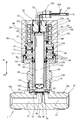
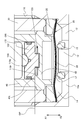
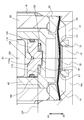
- FIG. 2 is a longitudinal sectional view of the valve device of FIG. 1 in an open state.
- the expanded sectional view of the principal part of the valve apparatus of FIG. The expanded sectional view of the principal part for demonstrating the state at the time of flow volume adjustment (at the time of flow volume reduction
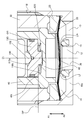
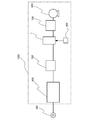
- the longitudinal cross-sectional view which shows the modification of the valve apparatus which concerns on one Embodiment of this invention. Schematic which shows the example of application to the semiconductor manufacturing process of the valve apparatus which concerns on one Embodiment of this invention.
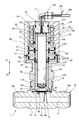
- FIG. 1 is a diagram showing a configuration of a valve device according to an embodiment of the present invention, showing a state in which the valve is fully closed
- FIG. 2 is an enlarged cross-sectional view of a main part of FIG.
- FIG. 5 is a diagram for explaining the operation of a piezoelectric actuator as an adjustment actuator.
- the upward direction is defined as the opening direction A1
- the downward direction is defined as the closing direction A2.
- 1, 1 is a valve device, 10 is a valve body, 20 is a diaphragm as a valve body, 38 is a diaphragm retainer, 30 is a bonnet, 40 is an operating member, 50 is a casing, 60 is a main actuator, 70 is an adjusting body, Reference numeral 80 denotes an actuator presser, 90 denotes a coil spring, 100 denotes a piezoelectric actuator as an adjustment actuator, 110 denotes an actuator receiver, 120 denotes a disc spring as an elastic member, and OR denotes an O-ring as a seal member.
- the valve body 10 is made of stainless steel, and has a block-shaped valve body main body 10a and connecting portions 10b and 10c that protrude from the sides of the valve body main body 10a, and define flow paths 12 and 13. ing. One ends of the flow paths 12 and 13 are opened at the end faces of the connecting portions 10b and 10c, respectively, and the other ends communicate with a concave valve chamber 14 whose upper side is open.
- a valve seat 15 made of synthetic resin (PFA, PA, PI, PCTFE, etc.) is fitted and fixed in a mounting groove provided at the opening periphery of the other end side of the flow path 12. In this embodiment, as is clear from FIG. 2, the valve seat 15 is fixed in the mounting groove by caulking.
- the diaphragm 20 is a valve body provided so that the flow paths 12 and 13 of the valve body 10 can be opened and closed.
- the diaphragm 20 is disposed above the valve seat 15 to maintain the airtightness of the valve chamber 14 and the central portion thereof. Moves up and down and contacts and separates from the valve seat 15 to open and close the flow paths 12 and 13.
- the diaphragm 20 is formed into a spherical shell shape in which a convex arc shape is in a natural state by causing the central portion of a metal thin plate such as special stainless steel and a nickel-cobalt alloy thin plate to bulge upward. ing.
- a diaphragm 20 is formed by laminating three sheets of the special stainless steel sheet and one sheet of the nickel / cobalt alloy sheet.
- the diaphragm 20 is mounted on the protruding portion of the inner peripheral surface of the valve chamber 14, and the lower end portion of the bonnet 30 inserted into the valve chamber 14 is screwed into the threaded portion 16 of the valve body 10, so that the diaphragm 20 is made of stainless steel. It is pressed to the projecting portion side of the valve body 10 through an alloy presser adapter 25 and is clamped and fixed in an airtight state.
- the nickel-cobalt alloy thin film is disposed on the gas contact side.
- other configurations can be used.
- the operation member 40 is a member for operating the diaphragm 20 so that the diaphragm 20 opens and closes the flow paths 12 and 13, is formed in a substantially cylindrical shape, is closed at the lower end side by the closing portion 48, and is opened at the upper end side.
- the bonnet 30 is fitted to the inner peripheral surface of the bonnet 30 and the inner peripheral surface of the cylindrical portion 51 formed in the casing 50, and is supported so as to be movable in the vertical direction.
- 1 and 2 are the opening and closing directions of the operating member 40, A1 is the opening direction, and A2 is the closing direction.
- the upward direction with respect to the valve body 10 is the opening direction A1, and the downward direction is the closing direction A2, but the present invention is not limited to this.
- a diaphragm presser 38 made of a synthetic resin such as polyimide that contacts the upper surface of the central portion of the diaphragm 20 is attached to the lower end surface of the operation member 40.
- a coil spring 90 is provided between the upper surface of the flange 45 formed on the outer peripheral surface of the operation member 40 and the ceiling surface of the casing, and the operation member 40 is always attached in the closing direction A2 by the coil spring 90. It is energized. For this reason, as shown in FIG. 2, in a state where the main actuator 60 is not operating, the diaphragm 20 is pressed against the valve seat 15 and the space between the flow paths 12 and 13 is closed.
- the flange 45 may be integrated with the operation member 40 or may be a separate body.
- the coil spring 90 is accommodated in a holding portion 52 formed between the inner peripheral surface of the casing 50 and the cylindrical portion 51.
- the coil spring 90 is used, it is not necessarily limited to this, Other types of springs, such as a disk spring and a leaf
- the casing 50 is fixed to the bonnet 30 by screwing the inner periphery of the lower end portion thereof into a screw portion 36 formed on the outer periphery of the upper end portion of the bonnet 30.
- An annular bulkhead 63 is fixed between the upper end surface of the bonnet 30 and the casing 50.
- Cylinder chambers C ⁇ b> 1 and C ⁇ b> 2 that are partitioned vertically by a bulkhead 63 are formed between the outer peripheral surface of the operation member 40 and the casing 50 and the bonnet 30.
- An annular piston 61 is fitted and inserted into the upper cylinder chamber C1, and an annular piston 62 is fitted and inserted into the lower cylinder chamber C2.
- These cylinder chambers C1, C2 and pistons 61, 62 constitute a main actuator 60 that moves the operating member 40 in the opening direction A1.
- the main actuator 60 can increase the force by the operation gas by using two pistons 61 and 62 to increase the working area of the pressure.
- the space above the piston 61 in the cylinder chamber C ⁇ b> 1 is connected to the atmosphere by the air passage 53.
- the space above the piston 62 in the cylinder chamber C2 is connected to the atmosphere by the ventilation path h1.
- the space below the pistons 61 and 62 in the cylinder chambers C1 and C2 is supplied with a high-pressure operation gas, so that the airtightness is maintained by the O-ring OR.
- These spaces communicate with flow passages 41 and 42 formed in the operation member 40, respectively.
- the flow paths 41 and 42 communicate with a flow path Ch formed between the inner peripheral surface of the operation member 40 and the outer peripheral surface of the case body 101 of the piezoelectric actuator 100, and the flow path Ch is located above the operation member 40.
- the end surface communicates with a space SP formed by the cylindrical portion 51 of the casing 50 and the lower end surface of the adjustment body 70.
- a flow path 81 formed in the annular actuator presser 80 connects the space SP and a flow path 71 that passes through the central portion of the adjustment body 70.
- the flow passage 71 of the adjustment body 70 communicates with the pipe 160 via the pipe joint 150.
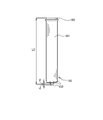
- the piezoelectric actuator 100 incorporates laminated piezoelectric elements (not shown) in the cylindrical case body 101 shown in FIG.
- the case main body 101 is made of a metal such as a stainless alloy, and the end surface on the hemispherical tip 102 side and the end surface on the base end 103 side are closed.
- the end surface of the case main body 101 on the front end portion 102 side is elastically deformed, and the hemispherical front end portion 102 is displaced in the longitudinal direction.
- the total length of the piezoelectric actuator 100 is L0 by applying a predetermined voltage V0 at which the elongation of the piezoelectric actuator 100 becomes d.
- V0 a voltage higher than the predetermined voltage V0
- the total length of the piezoelectric actuator 100 is L0 + d at the maximum, and when a voltage (including no voltage) lower than the predetermined voltage V0 is applied, the total length of the piezoelectric actuator 100 is the minimum L0. -D. Therefore, the full length from the front-end
- the tip 102 of the piezoelectric actuator 100 is hemispherical, but the present invention is not limited to this, and the tip may be a flat surface.
- power supply to the piezoelectric actuator 100 is performed by the wiring 105.
- the wiring 105 is led to the pipe 160 through the flow passage 71 of the adjustment body 70 and the pipe joint 150, and is drawn to the outside from the middle of the pipe 160.
- the position of the base end portion 103 of the piezoelectric actuator 100 in the opening / closing direction is defined by the lower end surface of the adjustment body 70 via the actuator presser 80.
- a screw portion provided on the outer peripheral surface of the adjustment body 70 is screwed into a screw hole 56 formed in the upper portion of the casing 50, and the position of the adjustment body 70 in the opening / closing directions A1 and A2 is adjusted.
- the tip portion 102 of the piezoelectric actuator 100 is in contact with a conical receiving surface 110a formed on the upper surface of the disk-shaped actuator receiver 110 as shown in FIG.
- the actuator receiver 110 is movable in the opening / closing directions A1 and A2.
- a disc spring 120 as an elastic member is provided between the lower surface of the actuator receiver 110 and the upper surface of the closing portion 48 of the operation member 40.
- the disc spring 120 is already compressed to some extent and elastically deformed, and the actuator receiver 110 is constantly urged in the opening direction A ⁇ b> 1 by the restoring force of the disc spring 120.
- the piezoelectric actuator 100 is also always urged in the opening direction A ⁇ b> 1, and the upper surface of the base end portion 103 is pressed against the actuator presser 80. Accordingly, the piezoelectric actuator 100 is disposed at a predetermined position with respect to the valve body 10.
- the piezoelectric actuator 100 Since the piezoelectric actuator 100 is not connected to any member, it can move relative to the operation member 40 in the opening and closing directions A1 and A2.
- the number and direction of the disc springs 120 can be appropriately changed according to conditions.
- other elastic members such as a coil spring and a leaf spring can be used.
- using a disc spring has an advantage that the spring rigidity, stroke, and the like can be easily adjusted.
- valve device 1 configured as described above will be described with reference to FIGS. 4 to 6B.
- the operation gas G having a predetermined pressure is supplied into the valve device 1 through the pipe 160, a thrust force that pushes the piston 61, 62 from the pistons 61, 62 to the operation member 40 in the opening direction A1 acts.
- the pressure of the operating gas G is set to a value sufficient to move the operating member 40 in the opening direction A1 against the biasing force in the closing direction A2 acting on the operating member 40 from the coil spring 90 and the disc spring 120. Yes.
- the operating member 40 moves in the opening direction A1 while further compressing the disc spring 120, and the operating member 40 is moved to the regulating surface 110t of the actuator receiver 110 as shown in FIG.
- the contact surface 40t comes into contact, and the actuator receiver 110 receives a force from the operation member 40 in the opening direction A1.
- This force acts as a force for compressing the piezoelectric actuator 100 in the opening / closing directions A1 and A2 through the tip portion 102 of the piezoelectric actuator 100, but the piezoelectric actuator 100 has sufficient rigidity to resist this force.
- the force in the opening direction A1 acting on the operation member 40 is received by the tip portion 102 of the piezoelectric actuator 100, and the movement of the operation member 40 in the A1 direction is restricted at the open position OP.
- the diaphragm 20 is separated from the valve seat 15 by the lift amount Lf described above.
- the piezoelectric actuator 100 is operated.
- the left side of the center line Ct in FIGS. 6A and 6B shows the state shown in FIG. 5, and the right side of the center line Ct shows the state after adjusting the positions of the operating members 40 in the opening and closing directions A1 and A2. .
- the piezoelectric actuator 100 is extended and the operation member 40 is moved in the closing direction A2.
- the lift amount Lf ⁇ after adjustment which is the distance between the diaphragm 20 and the valve seat 15, is smaller than the lift amount Lf before adjustment.
- the piezoelectric actuator 100 When adjusting in the direction in which the flow rate of the fluid is increased, as shown in FIG. 6B, the piezoelectric actuator 100 is shortened and the operation member 40 is moved in the opening direction A1. Thereby, the lift amount Lf + after adjustment which is the distance between the diaphragm 20 and the valve seat 15 becomes larger than the lift amount Lf before adjustment.
- the maximum lift amount of the diaphragm 20 is about 100 to 200 ⁇ m
- the adjustment amount by the piezoelectric actuator 100 is about ⁇ 20 ⁇ m. That is, the stroke of the piezoelectric actuator 100 cannot cover the lift amount of the diaphragm 20, but the main actuator 60 that operates with the operation gas G and the piezoelectric actuator 100 are used together, so that the main actuator 60 with a relatively long stroke is used. Therefore, the flow rate can be precisely adjusted by the piezoelectric actuator 100 having a relatively short stroke while the flow rate supplied by the valve device 1 is secured, and it is not necessary to manually adjust the flow rate by the adjustment body 70 or the like. Man-hours are greatly reduced. According to the present embodiment, precise flow rate adjustment is possible only by changing the voltage applied to the piezoelectric actuator 100. Therefore, the flow rate adjustment can be performed immediately and the flow rate can be controlled in real time.
- FIG. 7 shows a modification of the above embodiment.
- the adjustment body 70 is simply screwed into the screw hole 56 of the casing 50.
- the lock nut 180 is provided on the adjustment body 70A, and the lock nut 180 is screwed into the screw hole 56 for adjustment.
- the upper surface of the body 70A is pressed by the lower surface of the lock nut 180 to prevent the adjustment body 70A from rotating.
- the rotation of the adjustment body 70A can prevent problems such as the open position OP of the operation member 40 being shifted and the wiring 105 being twisted.
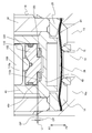
- a semiconductor manufacturing apparatus 1000 shown in FIG. 8 is an apparatus for performing a semiconductor manufacturing process by the ALD method.
- 300 is a process gas supply source
- 400 is a gas box
- 500 is a tank
- 600 is a control unit
- 700 is a processing chamber.
- 800 denote exhaust pumps.
- it is necessary to precisely adjust the flow rate of the processing gas, and it is also necessary to secure the flow rate of the processing gas to some extent by increasing the diameter of the substrate.
- the gas box 400 is an integrated gas system (fluid control) in which various fluid control devices such as an open / close valve, a regulator, and a mass flow controller are integrated and accommodated in the box in order to supply a precisely measured process gas to the processing chamber 700.
- the tank 500 functions as a buffer that temporarily stores the processing gas supplied from the gas box 400.
- the control unit 600 executes supply control of the operation gas G to the valve device 1 and flow rate adjustment control by the piezoelectric actuator 100.
- the processing chamber 700 provides a sealed processing space for forming a film on a substrate by the ALD method.
- the exhaust pump 800 evacuates the processing chamber 700.
- the processing gas can be initially adjusted by sending a command for adjusting the flow rate from the control unit 600 to the valve device 1. Further, even when the film forming process is being performed in the processing chamber 700, the flow rate of the processing gas can be adjusted, and the processing gas flow rate can be optimized in real time.
- valve device 1 is used in a semiconductor manufacturing process by the ALD method.
- the present invention is not limited to this, and the present invention is, for example, an atomic layer etching method (ALE: Atomic Layer Etching method). It can be applied to any object that requires precise flow rate adjustment.
- ALE Atomic Layer Etching method
- the piston built in the cylinder chamber operated by gas pressure is used as the main actuator.
- the present invention is not limited to this, and various optimum actuators can be selected according to the object to be controlled. It is.
- the piezoelectric actuator is used as the adjustment actuator.
- a motor such as a stepping motor and a mechanism such as a ball screw and a nut that convert rotational motion into linear motion
- Various actuators such as a coil and a thermoactuator that expands and contracts due to a temperature change can be adopted.
- the piezoelectric actuator 100 has low heat release, heat resistance of hundreds of degrees Celsius, can be always operated not only during initial adjustment but also during fluid control, and has low non-linear characteristics such as backlash during expansion and contraction. Therefore, it is preferable as the adjusting actuator of the present invention in that the positioning accuracy is very high and a relatively large compressive load can be supported.
- the piezoelectric actuator 100 is responsible for highly accurate control of the position of the operation member 40 thereafter.
- the maximum stroke of the actuator can be reduced as much as possible (the piezoelectric actuator can be miniaturized), and the position of the operation member 40 can be finely adjusted and the position can be controlled with high accuracy.
- a so-called normally closed type valve has been described as an example, but the present invention is not limited to this, and can be applied to a normally open type valve.
- the opening degree of the valve body may be adjusted by an adjustment actuator.
- the piezoelectric actuator 100 is configured to support (accept) the force acting on the operation member 40.
- the present invention is not limited to this, and the operation member 40 is positioned at the open position OP.
- the adjustment actuator can be used to adjust only the position of the operation member 40 in the opening / closing direction without supporting the force acting on the operation member 40.
- valve body the diaphragm is exemplified as the valve body, but the present invention is not limited to this, and other types of valve bodies may be employed.
- valve device 1 is arranged outside the gas box 400 as a fluid control device.
- the fluid control in which various fluid devices such as open / close valves, regulators, and mass flow controllers are integrated and accommodated in the box. It is also possible to include the valve device 1 of the above embodiment in the device.
Landscapes
- Engineering & Computer Science (AREA)
- General Engineering & Computer Science (AREA)
- Mechanical Engineering (AREA)
- Physics & Mathematics (AREA)
- Power Engineering (AREA)
- Condensed Matter Physics & Semiconductors (AREA)
- General Physics & Mathematics (AREA)
- Manufacturing & Machinery (AREA)
- Computer Hardware Design (AREA)
- Microelectronics & Electronic Packaging (AREA)
- Chemical & Material Sciences (AREA)
- Automation & Control Theory (AREA)
- Chemical Kinetics & Catalysis (AREA)
- Fluid Mechanics (AREA)
- Electrically Driven Valve-Operating Means (AREA)
- Chemical Vapour Deposition (AREA)
- Fluid-Driven Valves (AREA)
- Lift Valve (AREA)
Priority Applications (6)
| Application Number | Priority Date | Filing Date | Title |
|---|---|---|---|
| US16/347,934 US11098819B2 (en) | 2016-11-08 | 2017-11-02 | Valve device, flow control method using the same, and semiconductor manufacturing method |
| KR1020197015535A KR20190077477A (ko) | 2016-11-08 | 2017-11-02 | 밸브 장치, 이 밸브 장치를 사용한 유량제어방법 및 반도체 제조 방법 |
| JP2018513389A JP6336692B1 (ja) | 2016-11-08 | 2017-11-02 | バルブ装置、このバルブ装置を用いた流量制御方法および半導体製造方法 |
| EP17869179.6A EP3540280A4 (en) | 2016-11-08 | 2017-11-02 | VALVE DEVICE, METHOD FOR CONTROLLING THE FLOW RATE WITH THIS VALVE DEVICE AND METHOD FOR PRODUCING A SEMICONDUCTOR |
| CN201780069196.1A CN109952459B (zh) | 2016-11-08 | 2017-11-02 | 阀装置、使用该阀装置的流量控制方法和半导体制造方法 |
| KR1020217019061A KR102312480B1 (ko) | 2016-11-08 | 2017-11-02 | 밸브 장치, 이 밸브 장치를 사용한 유량제어방법 및 반도체 제조 방법 |
Applications Claiming Priority (2)
| Application Number | Priority Date | Filing Date | Title |
|---|---|---|---|
| JP2016218093 | 2016-11-08 | ||
| JP2016-218093 | 2016-11-08 |
Publications (1)
| Publication Number | Publication Date |
|---|---|
| WO2018088326A1 true WO2018088326A1 (ja) | 2018-05-17 |
Family
ID=62110580
Family Applications (1)
| Application Number | Title | Priority Date | Filing Date |
|---|---|---|---|
| PCT/JP2017/039729 WO2018088326A1 (ja) | 2016-11-08 | 2017-11-02 | バルブ装置、このバルブ装置を用いた流量制御方法および半導体製造方法 |
Country Status (7)
| Country | Link |
|---|---|
| US (1) | US11098819B2 (zh) |
| EP (1) | EP3540280A4 (zh) |
| JP (2) | JP6336692B1 (zh) |
| KR (2) | KR102312480B1 (zh) |
| CN (1) | CN109952459B (zh) |
| TW (1) | TWI671483B (zh) |
| WO (1) | WO2018088326A1 (zh) |
Cited By (6)
| Publication number | Priority date | Publication date | Assignee | Title |
|---|---|---|---|---|
| WO2019059043A1 (ja) * | 2017-09-25 | 2019-03-28 | 株式会社フジキン | バルブ装置、流量調整方法、流体制御装置、流量制御方法、半導体製造装置および半導体製造方法 |
| JPWO2018100968A1 (ja) * | 2016-11-30 | 2019-10-17 | 株式会社フジキン | バルブ装置、このバルブ装置を用いた流量制御方法および半導体製造方法 |
| KR20190124274A (ko) | 2017-06-22 | 2019-11-04 | 가부시키가이샤 후지킨 | 유량 제어 장치 및 유량 제어 장치의 유량 제어 방법 |
| WO2020158573A1 (ja) * | 2019-01-31 | 2020-08-06 | 株式会社フジキン | バルブ装置、流量制御方法、流体制御装置、半導体製造方法、および半導体製造装置 |
| WO2020158459A1 (ja) * | 2019-01-31 | 2020-08-06 | 株式会社フジキン | バルブ装置、このバルブ装置を用いた流量制御方法、流体制御装置、半導体製造方法、および半導体製造装置 |
| JP2020122539A (ja) * | 2019-01-31 | 2020-08-13 | 株式会社フジキン | バルブ装置、このバルブ装置を用いた流量制御方法、半導体製造方法、および半導体製造装置 |
Families Citing this family (6)
| Publication number | Priority date | Publication date | Assignee | Title |
|---|---|---|---|---|
| WO2020044827A1 (ja) * | 2018-08-30 | 2020-03-05 | 株式会社フジキン | 流体制御機器 |
| CN110307351A (zh) * | 2019-07-10 | 2019-10-08 | 广东工业大学 | 一种压电陶瓷限流阀 |
| IL268254B2 (en) * | 2019-07-24 | 2024-10-01 | Ham Let Israel Canada Ltd | Flow control accessory |
| JP7382054B2 (ja) * | 2019-08-29 | 2023-11-16 | 株式会社フジキン | バルブ装置および流量制御装置 |
| US11927274B2 (en) | 2019-11-25 | 2024-03-12 | M-System Co., Ltd. | Actuator and fluid control device |
| KR20230131613A (ko) | 2022-03-07 | 2023-09-14 | 주식회사 코일넷 | 미생물 분뇨처리조가 구비된 변기 |
Citations (4)
| Publication number | Priority date | Publication date | Assignee | Title |
|---|---|---|---|---|
| JPH08170755A (ja) * | 1994-12-20 | 1996-07-02 | Koganei Corp | 流体圧作動弁装置 |
| WO2004079243A1 (ja) * | 2003-03-07 | 2004-09-16 | Ckd Corporation | 流量制御弁 |
| JP2007064333A (ja) | 2005-08-30 | 2007-03-15 | Fujikin Inc | ダイレクトタッチ型メタルダイヤフラム弁 |
| JP2016121776A (ja) | 2014-12-25 | 2016-07-07 | 株式会社フジキン | 流体制御器 |
Family Cites Families (15)
| Publication number | Priority date | Publication date | Assignee | Title |
|---|---|---|---|---|
| US5092360A (en) | 1989-11-14 | 1992-03-03 | Hitachi Metals, Ltd. | Flow rated control valve using a high-temperature stacked-type displacement device |
| JPH10318385A (ja) | 1997-05-21 | 1998-12-04 | Hitachi Metals Ltd | 金属ダイアフラム式流量調節弁 |
| JP2001317646A (ja) | 2000-05-08 | 2001-11-16 | Smc Corp | 圧電式流体制御弁 |
| IT1320475B1 (it) | 2000-06-30 | 2003-11-26 | Fiat Ricerche | Attuatore piezoelettrico autocompensato per una valvola di controllo. |
| KR100812560B1 (ko) | 2005-09-07 | 2008-03-13 | 씨케이디 가부시키 가이샤 | 유량 제어 밸브 |
| JP4743763B2 (ja) | 2006-01-18 | 2011-08-10 | 株式会社フジキン | 圧電素子駆動式金属ダイヤフラム型制御弁 |
| JP4933936B2 (ja) * | 2007-03-30 | 2012-05-16 | 株式会社フジキン | 圧電素子駆動式制御弁 |
| JP5082989B2 (ja) * | 2008-03-31 | 2012-11-28 | 日立金属株式会社 | 流量制御装置、その検定方法及び流量制御方法 |
| US20130000759A1 (en) | 2011-06-30 | 2013-01-03 | Agilent Technologies, Inc. | Microfluidic device and external piezoelectric actuator |
| US8783652B2 (en) * | 2012-03-12 | 2014-07-22 | Mps Corporation | Liquid flow control for film deposition |
| JP5775110B2 (ja) * | 2013-03-26 | 2015-09-09 | 株式会社フジキン | 流量制御装置用の流量制御弁 |
| JP2018513389A (ja) * | 2015-03-13 | 2018-05-24 | テクノプローベ エス.ピー.エー. | 様々な動作状態での試験ヘッドでのプローブ保持を適正化し、各々のガイドホールでのスライドを改善するバーチカルプローブをもつ試験ヘッド |
| JP7150340B2 (ja) | 2017-06-22 | 2022-10-11 | 株式会社フジキン | 流量制御装置および流量制御装置の流量制御方法 |
| WO2019059040A1 (ja) | 2017-09-25 | 2019-03-28 | 株式会社フジキン | バルブ装置、調整情報生成方法、流量調整方法、流体制御装置、流量制御方法、半導体製造装置および半導体製造方法 |
| KR102210582B1 (ko) | 2017-09-25 | 2021-02-02 | 가부시키가이샤 후지킨 | 밸브장치, 유량 조정방법, 유체 제어장치, 유량 제어방법, 반도체 제조장치 및 반도체 제조방법 |
-
2017
- 2017-11-02 KR KR1020217019061A patent/KR102312480B1/ko active IP Right Grant
- 2017-11-02 EP EP17869179.6A patent/EP3540280A4/en active Pending
- 2017-11-02 CN CN201780069196.1A patent/CN109952459B/zh not_active Expired - Fee Related
- 2017-11-02 US US16/347,934 patent/US11098819B2/en active Active
- 2017-11-02 JP JP2018513389A patent/JP6336692B1/ja active Active
- 2017-11-02 WO PCT/JP2017/039729 patent/WO2018088326A1/ja active Application Filing
- 2017-11-02 KR KR1020197015535A patent/KR20190077477A/ko active Application Filing
- 2017-11-07 TW TW106138368A patent/TWI671483B/zh active
-
2018
- 2018-05-02 JP JP2018088543A patent/JP2018132195A/ja active Pending
Patent Citations (4)
| Publication number | Priority date | Publication date | Assignee | Title |
|---|---|---|---|---|
| JPH08170755A (ja) * | 1994-12-20 | 1996-07-02 | Koganei Corp | 流体圧作動弁装置 |
| WO2004079243A1 (ja) * | 2003-03-07 | 2004-09-16 | Ckd Corporation | 流量制御弁 |
| JP2007064333A (ja) | 2005-08-30 | 2007-03-15 | Fujikin Inc | ダイレクトタッチ型メタルダイヤフラム弁 |
| JP2016121776A (ja) | 2014-12-25 | 2016-07-07 | 株式会社フジキン | 流体制御器 |
Non-Patent Citations (1)
| Title |
|---|
| See also references of EP3540280A4 |
Cited By (21)
| Publication number | Priority date | Publication date | Assignee | Title |
|---|---|---|---|---|
| JPWO2018100968A1 (ja) * | 2016-11-30 | 2019-10-17 | 株式会社フジキン | バルブ装置、このバルブ装置を用いた流量制御方法および半導体製造方法 |
| KR20190124274A (ko) | 2017-06-22 | 2019-11-04 | 가부시키가이샤 후지킨 | 유량 제어 장치 및 유량 제어 장치의 유량 제어 방법 |
| US11035494B2 (en) | 2017-06-22 | 2021-06-15 | Fujikin Incorporated | Flow rate control apparatus and flow rate control method for the flow rate control apparatus |
| WO2019059043A1 (ja) * | 2017-09-25 | 2019-03-28 | 株式会社フジキン | バルブ装置、流量調整方法、流体制御装置、流量制御方法、半導体製造装置および半導体製造方法 |
| US11506290B2 (en) | 2017-09-25 | 2022-11-22 | Fujikin Incorporated | Valve apparatus, flow rate adjusting method, fluid control apparatus, flow rate control method, semiconductor manufacturing apparatus, and semiconductor manufacturing method |
| JP2020122539A (ja) * | 2019-01-31 | 2020-08-13 | 株式会社フジキン | バルブ装置、このバルブ装置を用いた流量制御方法、半導体製造方法、および半導体製造装置 |
| KR20210118163A (ko) | 2019-01-31 | 2021-09-29 | 가부시키가이샤 후지킨 | 밸브장치, 이 밸브장치를 사용한 유량 제어방법, 유체 제어장치, 반도체 제조방법, 및 반도체 제조장치 |
| TWI727633B (zh) * | 2019-01-31 | 2021-05-11 | 日商富士金股份有限公司 | 閥裝置、利用該閥裝置之流量控制方法、流體控制裝置、半導體製造方法及半導體製造裝置 |
| WO2020158459A1 (ja) * | 2019-01-31 | 2020-08-06 | 株式会社フジキン | バルブ装置、このバルブ装置を用いた流量制御方法、流体制御装置、半導体製造方法、および半導体製造装置 |
| CN113366253A (zh) * | 2019-01-31 | 2021-09-07 | 株式会社富士金 | 阀装置、使用该阀装置的流量控制方法、流体控制装置、半导体制造方法、以及半导体制造装置 |
| CN113423987A (zh) * | 2019-01-31 | 2021-09-21 | 株式会社富士金 | 阀装置、流量控制方法、流体控制装置、半导体制造方法以及半导体制造装置 |
| KR20210118162A (ko) | 2019-01-31 | 2021-09-29 | 가부시키가이샤 후지킨 | 밸브장치, 유량 제어방법, 유체 제어장치, 반도체 제조방법, 및 반도체 제조장치 |
| TWI727634B (zh) * | 2019-01-31 | 2021-05-11 | 日商富士金股份有限公司 | 閥裝置、流量控制方法、流體控制裝置、半導體製造方法及半導體製造裝置 |
| JPWO2020158459A1 (ja) * | 2019-01-31 | 2021-12-02 | 株式会社フジキン | バルブ装置、このバルブ装置を用いた流量制御方法、流体制御装置、半導体製造方法、および半導体製造装置 |
| JPWO2020158573A1 (ja) * | 2019-01-31 | 2021-12-09 | 株式会社フジキン | バルブ装置、流量制御方法、流体制御装置、半導体製造方法、および半導体製造装置 |
| WO2020158573A1 (ja) * | 2019-01-31 | 2020-08-06 | 株式会社フジキン | バルブ装置、流量制御方法、流体制御装置、半導体製造方法、および半導体製造装置 |
| US11598430B2 (en) | 2019-01-31 | 2023-03-07 | Fujikin Incorporated | Valve device, flow rate control method, fluid control device, semiconductor manufacturing method, and semiconductor manufacturing apparatus using the valve device |
| KR102542263B1 (ko) * | 2019-01-31 | 2023-06-13 | 가부시키가이샤 후지킨 | 밸브장치, 이 밸브장치를 사용한 유량 제어방법, 유체 제어장치, 반도체 제조방법, 및 반도체 제조장치 |
| JP7308506B2 (ja) | 2019-01-31 | 2023-07-14 | 株式会社フジキン | バルブ装置、このバルブ装置を用いた流量制御方法、半導体製造方法、および半導体製造装置 |
| JP7352971B2 (ja) | 2019-01-31 | 2023-09-29 | 株式会社フジキン | バルブ装置、流量制御方法、流体制御装置、半導体製造方法、および半導体製造装置 |
| JP7389492B2 (ja) | 2019-01-31 | 2023-11-30 | 株式会社フジキン | バルブ装置、このバルブ装置を用いた流量制御方法、流体制御装置、半導体製造方法、および半導体製造装置 |
Also Published As
| Publication number | Publication date |
|---|---|
| EP3540280A1 (en) | 2019-09-18 |
| CN109952459B (zh) | 2021-02-26 |
| KR20190077477A (ko) | 2019-07-03 |
| KR20210079403A (ko) | 2021-06-29 |
| TW201825817A (zh) | 2018-07-16 |
| US11098819B2 (en) | 2021-08-24 |
| US20190285176A1 (en) | 2019-09-19 |
| JPWO2018088326A1 (ja) | 2018-11-15 |
| JP2018132195A (ja) | 2018-08-23 |
| EP3540280A4 (en) | 2019-11-27 |
| JP6336692B1 (ja) | 2018-06-06 |
| TWI671483B (zh) | 2019-09-11 |
| KR102312480B1 (ko) | 2021-10-14 |
| CN109952459A (zh) | 2019-06-28 |
Similar Documents
| Publication | Publication Date | Title |
|---|---|---|
| JP6336692B1 (ja) | バルブ装置、このバルブ装置を用いた流量制御方法および半導体製造方法 | |
| JP6923220B2 (ja) | バルブ装置、このバルブ装置を用いた流量制御方法および半導体製造方法 | |
| JP7113529B2 (ja) | バルブ装置、流量調整方法、流体制御装置、流量制御方法、半導体製造装置および半導体製造方法 | |
| JP7030359B2 (ja) | バルブ装置 | |
| JP7174430B2 (ja) | バルブ装置、調整情報生成方法、流量調整方法、流体制御装置、流量制御方法、半導体製造装置および半導体製造方法 | |
| US11174949B2 (en) | Actuator and valve device using the same | |
| US20220082176A1 (en) | Valve device, flow control method, fluid control device, semiconductor manufacturing method, and semiconductor manufacturing apparatus | |
| JPWO2019171604A1 (ja) | バルブ装置 | |
| US11598430B2 (en) | Valve device, flow rate control method, fluid control device, semiconductor manufacturing method, and semiconductor manufacturing apparatus using the valve device |
Legal Events
| Date | Code | Title | Description |
|---|---|---|---|
| WWE | Wipo information: entry into national phase |
Ref document number: 2018513389 Country of ref document: JP |
|
| 121 | Ep: the epo has been informed by wipo that ep was designated in this application |
Ref document number: 17869179 Country of ref document: EP Kind code of ref document: A1 |
|
| NENP | Non-entry into the national phase |
Ref country code: DE |
|
| ENP | Entry into the national phase |
Ref document number: 20197015535 Country of ref document: KR Kind code of ref document: A |
|
| ENP | Entry into the national phase |
Ref document number: 2017869179 Country of ref document: EP Effective date: 20190611 |