WO2018088181A1 - 外装通気部材 - Google Patents
外装通気部材 Download PDFInfo
- Publication number
- WO2018088181A1 WO2018088181A1 PCT/JP2017/038167 JP2017038167W WO2018088181A1 WO 2018088181 A1 WO2018088181 A1 WO 2018088181A1 JP 2017038167 W JP2017038167 W JP 2017038167W WO 2018088181 A1 WO2018088181 A1 WO 2018088181A1
- Authority
- WO
- WIPO (PCT)
- Prior art keywords
- exterior
- corrugated tube
- tubular member
- outer periphery
- communication hole
- Prior art date
- Legal status (The legal status is an assumption and is not a legal conclusion. Google has not performed a legal analysis and makes no representation as to the accuracy of the status listed.)
- Ceased
Links
Images

Classifications
-
- H—ELECTRICITY
- H02—GENERATION; CONVERSION OR DISTRIBUTION OF ELECTRIC POWER
- H02G—INSTALLATION OF ELECTRIC CABLES OR LINES, OR OF COMBINED OPTICAL AND ELECTRIC CABLES OR LINES
- H02G15/00—Cable fittings
- H02G15/013—Sealing means for cable inlets
-
- H—ELECTRICITY
- H02—GENERATION; CONVERSION OR DISTRIBUTION OF ELECTRIC POWER
- H02G—INSTALLATION OF ELECTRIC CABLES OR LINES, OR OF COMBINED OPTICAL AND ELECTRIC CABLES OR LINES
- H02G3/00—Installations of electric cables or lines or protective tubing therefor in or on buildings, equivalent structures or vehicles
- H02G3/02—Details
- H02G3/04—Protective tubing or conduits, e.g. cable ladders or cable troughs
- H02G3/0462—Tubings, i.e. having a closed section
- H02G3/0468—Corrugated
-
- B—PERFORMING OPERATIONS; TRANSPORTING
- B60—VEHICLES IN GENERAL
- B60R—VEHICLES, VEHICLE FITTINGS, OR VEHICLE PARTS, NOT OTHERWISE PROVIDED FOR
- B60R16/00—Electric or fluid circuits specially adapted for vehicles and not otherwise provided for; Arrangement of elements of electric or fluid circuits specially adapted for vehicles and not otherwise provided for
- B60R16/02—Electric or fluid circuits specially adapted for vehicles and not otherwise provided for; Arrangement of elements of electric or fluid circuits specially adapted for vehicles and not otherwise provided for electric constitutive elements
- B60R16/0207—Wire harnesses
- B60R16/0215—Protecting, fastening and routing means therefor
-
- H—ELECTRICITY
- H02—GENERATION; CONVERSION OR DISTRIBUTION OF ELECTRIC POWER
- H02G—INSTALLATION OF ELECTRIC CABLES OR LINES, OR OF COMBINED OPTICAL AND ELECTRIC CABLES OR LINES
- H02G15/00—Cable fittings
-
- H—ELECTRICITY
- H02—GENERATION; CONVERSION OR DISTRIBUTION OF ELECTRIC POWER
- H02G—INSTALLATION OF ELECTRIC CABLES OR LINES, OR OF COMBINED OPTICAL AND ELECTRIC CABLES OR LINES
- H02G3/00—Installations of electric cables or lines or protective tubing therefor in or on buildings, equivalent structures or vehicles
- H02G3/02—Details
- H02G3/04—Protective tubing or conduits, e.g. cable ladders or cable troughs
- H02G3/0406—Details thereof
- H02G3/0418—Covers or lids; Their fastenings
-
- H—ELECTRICITY
- H02—GENERATION; CONVERSION OR DISTRIBUTION OF ELECTRIC POWER
- H02G—INSTALLATION OF ELECTRIC CABLES OR LINES, OR OF COMBINED OPTICAL AND ELECTRIC CABLES OR LINES
- H02G3/00—Installations of electric cables or lines or protective tubing therefor in or on buildings, equivalent structures or vehicles
- H02G3/02—Details
- H02G3/06—Joints for connecting lengths of protective tubing or channels, to each other or to casings, e.g. to distribution boxes; Ensuring electrical continuity in the joint
Definitions
- the present invention relates to an exterior ventilation member.
- Patent Document 1 discloses a cylindrical waterproof cover made of rubber or elastomer that is attached to a terminal of an exterior material through which a high-voltage wire harness is sealed and inserted.
- a ventilation film is attached to the peripheral wall of the waterproof cover, and air can be circulated between the inside and outside of the waterproof cover through the ventilation film. Thereby, the pressure in the waterproof cover is adjusted, and the waterproof cover is prevented from being excessively expanded due to a rapid temperature rise.
- the present invention has been completed based on the above-described circumstances, and an object thereof is to alleviate restrictions on the layout with respect to the arrangement of the gas permeable membrane.
- the present invention A tubular member through which an electric wire can be inserted and in which a communication hole is formed in the outer peripheral surface;
- a holding member having an exterior part that is sheathed on the outer periphery of the tubular member, and an attachment part that is open and formed on the outer periphery of the exterior part and communicates with the inside of the tubular member via the communication hole;
- the position of the gas permeable membrane in the axial direction of the tubular member can be arbitrarily set by appropriately changing the position of the communication hole formed in the tubular member. Therefore, according to the invention of the present application, it is possible to relax the restrictions on the layout regarding the arrangement of the gas permeable membrane.
- the present invention may be configured such that the exterior part is exteriorized over an area of at least a half circumference or more in the circumferential direction of the tubular member. According to this configuration, the holding member can be temporarily held with respect to the tubular member in a state before the fixing member is fixed.
- the exterior portion may be made of a material having elasticity, and may be elastically deformed so as to be separated from the outer periphery of the tubular member. According to this configuration, the holding member can be attached so as to approach the tubular member in the radial direction by expanding and deforming the exterior portion.
- the present invention may include a cylindrical positioning portion that is formed on the holding member and protrudes from the attachment portion toward the inner peripheral side and is accommodated in the tubular member from the communication hole. According to this configuration, in a state before the holding member is fixed to the tubular member by the fixing member, the holding member can be positioned so that the attachment portion corresponds to the communication hole by accommodating the positioning portion in the communication hole. it can.
- the present invention may be provided with a retaining protrusion formed on the outer periphery of the positioning portion and engaged with a hole edge portion of the communication hole on the inner periphery of the tubular member. According to this configuration, in the state before the holding member is fixed to the tubular member by the fixing member, the holding member can be temporarily held by the tubular member by locking the retaining protrusion to the hole edge of the communication hole. it can.
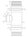
- the exterior ventilation member A of this embodiment includes a corrugated tube 10 made of a synthetic resin (a tubular member described in claims), a holding member 20 having rubber elasticity such as an elastomer, a ventilation membrane unit 30, and a holding member 20.
- a pair of tie bands 38 fixing members described in claims) for fixing to the corrugated tube 10 are provided.
- the corrugated tube 10 has a tubular shape with a circular cross section. Since the corrugated tube 10 has a bellows shape over its entire length, the corrugated tube 10 can be elastically deformed in such a manner that its axis is curved.
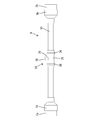
- a high-voltage electric wire W used for an electric vehicle or a hybrid vehicle is inserted inside the corrugated tube 10.
- connectors Ca and Cb provided on, for example, an inverter, a battery, and a motor are connected to both ends of the electric wire W.
- end portions on the small diameter side of the grommets Ga and Gb made of elastomer and having rubber elasticity are hermetically sealed.
- the large diameter side ends of the grommets Ga and Gb are hermetically sealed on the connectors Ca and Cb.
- a sealed space S surrounded by the corrugated tube 10 and the grommets Ga and Gb is formed between the pair of connectors Ca and Cb, and the electric wire W is accommodated in the sealed space S.
- a communication hole 11 is formed on the outer periphery of the corrugated tube 10 to communicate the outside and the inside of the corrugated tube 10.
- the formation position of the communication hole 11 in the axial direction of the corrugated tube 10 is set to the same position as the position where the air-permeable membrane 34 described later is to be disposed.
- the communication hole 11 can be formed at any position in the axial direction of the corrugated tube 10 and can be formed at any position in the circumferential direction of the corrugated tube 10.
- On the outer periphery of the corrugated tube 10 a plurality of circumferential recesses 12 and a plurality of circumferential projections 13 are formed alternately in the axial direction.
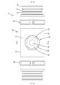
- the holding member 20 is a single member having an exterior part 21, an attachment part 26, and a positioning part 28.
- the exterior portion 21 includes a pair of front and rear arc-shaped plate portions 22 having a substantially semicircular arc shape, and has a substantially cylindrical shape that surrounds the outer periphery of the corrugated tube 10 over substantially the entire circumference.
- a slit 23 along the axial direction is formed in the exterior portion 21 along the entire length, and the pair of arc-shaped plate portions 22 are separated from the outer peripheral surface of the corrugated tube 10 while increasing the opening width of the slit 23. It can be elastically deformed in form.
- a rib 24 that fits into the concave portion 12 on the outer periphery of the corrugated tube 10 and a groove portion 25 that fits into the convex portion 13 on the outer periphery of the corrugated tube 10 are formed.
- the mounting portion 26 has a form protruding in a cylindrical shape from the outer periphery of the exterior portion 21 outward in the radial direction.
- the attachment portion 26 is disposed at a central portion in the axial direction of the exterior portion 21, and is disposed at a boundary portion between the pair of arc-shaped plate portions 22 in the circumferential direction of the exterior portion 21.
- a plurality of locking protrusions 27 along the circumferential direction are formed on the inner periphery of the attachment portion 26 with a gap in the axial direction of the attachment portion 26.
- the positioning portion 28 has a shape protruding in an annular shape from the inner periphery of the exterior portion 21 inward in the radial direction.
- the positioning portion 28 is arranged coaxially with the mounting portion 26.
- the outer diameter of the positioning portion 28 is the same as or slightly smaller than the inner diameter of the communication hole 11 of the corrugated tube 10.
- a retaining projection 29 is formed on the outer periphery of the positioning portion 28.
- the gas permeable membrane unit 30 is a single member in which a cylindrical member 31 made of a synthetic resin having higher rigidity than the holding member 20 and the gas permeable membrane 34 are integrated.
- a plurality of locking grooves 32 along the circumferential direction are formed on the outer periphery of the cylindrical member 31 at intervals in the axial direction of the cylindrical member 31.
- An enlarged diameter portion 33 is formed on the outer periphery of the distal end portion of the cylindrical member 31.
- the gas permeable membrane 34 has a characteristic that allows air (gas) to pass therethrough but does not allow liquid or fixation to pass therethrough.
- the gas permeable membrane 34 is integrated with the cap 35 by molding or the like.
- the cap 35 is attached to the distal end portion of the cylindrical member 31 via the seal ring 36 and closes the opening 37 at the distal end portion of the cylindrical member 31 in an airtight manner.
- the gas permeable membrane unit 30 is attached to the holding member 20 by fitting the cylindrical member 31 into the attachment portion 26 from the base end side.
- the plurality of locking grooves 32 on the outer periphery of the cylindrical member 31 and the plurality of locking protrusions 27 on the inner periphery of the mounting portion 26 are locked in close contact.
- the gas permeable membrane unit 30 is held in a state of being attached to the holding member 20, and the gap between the inner periphery of the attachment portion 26 and the outer periphery of the cylindrical member 31 is held in an airtight state.
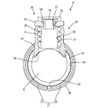
- the holding member 20 to which the gas permeable membrane unit 30 is attached is attached so as to cover the communication hole 11 and the surrounding area in the outer periphery of the corrugated tube 10.
- the pair of arc-shaped plate portions 22 are elastically deformed so as to expand, and the slits 23 are greatly expanded, and the expanded arc-shaped plate portions 22 are placed on the outer periphery of the corrugated tube 10.
- the positioning portion 28 is inserted into the communication hole 11. By this insertion, the holding member 20 is positioned with respect to the corrugated tube 10 in the axial direction and the circumferential direction.
- the holding member 20 is positioned in the axial direction with respect to the corrugated tube 10.
- the retaining protrusion 29 is locked to the edge of the communication hole 11 on the inner periphery of the corrugated tube 10.
- the holding member 20 is restricted from being detached from the corrugated tube 10 in the radial direction.
- the pair of arc-shaped plate portions 22 are elastically restored to a substantially semicircular arc shape, and the exterior portion 21 returns to a substantially cylindrical shape.
- the exterior portion 21 surrounds the corrugated tube 10 so as to be in close contact with the entire circumference. Due to the surrounding of the exterior portion 21, the holding member 20 is in a state in which detachment in the radial direction is restricted with respect to the corrugated tube 10.
- the tie band 38 is a member made of synthetic resin having a well-known structure that cannot be loosened once it is tightened.
- the positions where the tie band 38 is wound are two positions that are spaced apart in the axial direction of the corrugated tube 10 and sandwich the attachment portion 26.
- the air in the sealed space S flows out of the corrugated tube 10 through the communication hole 11, the tubular member 31, and the ventilation film 34, and is sealed. Since the atmospheric pressure in the space S is maintained at substantially the same pressure as the atmospheric pressure, there is no possibility that the grommets Ga and Gb will be excessively expanded.
- the air pressure in the sealed space S decreases, the air outside the corrugated tube 10 flows into the sealed space S through a path opposite to the above. Is maintained at approximately the same pressure as atmospheric pressure.
- the exterior ventilation member A of the present embodiment includes the corrugated tube 10, the holding member 20, the ventilation film 34, and the tie band 38.
- the corrugated tube 10 allows the electric wire W to be inserted, and a communication hole 11 is opened on the outer peripheral surface of the corrugated tube 10.
- the holding member 20 includes an exterior part 21 that is externally provided on the outer periphery of the corrugated tube 10, and an attachment part 26 that is formed so as to open on the outer periphery of the external part 21.
- the attachment portion 26 communicates with the interior (sealed space S) of the corrugated tube 10 via the communication hole 11, and a ventilation film 34 is attached to the attachment portion 26.
- the exterior portion 21 is fixed to the outer periphery of the corrugated tube 10 by the tie band 38.
- the position of the ventilation film 34 in the axial direction of the corrugated tube 10 and the position of the corrugated tube 10 and the corrugated tube 10 are appropriately changed by changing the position in the axial direction and the circumferential position of the communication hole 11 formed in the corrugated tube 10.
- the position of the gas permeable membrane 34 in the circumferential direction can be arbitrarily set.
- the orientation of the gas permeable membrane 34 can be arbitrarily set by changing the shape of the attachment portion 26 and the position where the gas permeable membrane 34 is attached. Therefore, according to the exterior ventilation member A of the present embodiment, layout restrictions regarding the arrangement of the ventilation film 34 can be relaxed.
- the exterior portion 21 is configured to be exteriorized over an area (substantially the entire circumference) of at least a half circumference in the circumferential direction of the corrugated tube 10. Therefore, the holding member 20 can be temporarily held with respect to the corrugated tube 10 in a state before the tie band 38 fixes the exterior portion 21 (holding member 20) to the corrugated tube 10.
- the exterior portion 21 is made of an elastic material (elastomer, rubber, or the like) and can be elastically deformed so as to be separated from the outer periphery of the corrugated tube 10.
- the holding member 20 can be attached so as to approach the corrugated tube 10 in the radial direction by expanding and deforming the exterior portion 21. Therefore, the workability when attaching the holding member 20 to the corrugated tube 10 is better than when the exterior portion 21 (holding member 20) is covered on one end of the corrugated tube 10 and then slid in the axial direction. .
- the holding member 20 is formed with a cylindrical positioning portion 28 that protrudes from the attachment portion 26 toward the inner peripheral side and is accommodated in the corrugated tube 10 from the communication hole 11. According to this configuration, before the holding member 20 is fixed to the corrugated tube 10 with the tie band 38, the mounting portion 26 corresponds to the communication hole 11 by fitting the positioning portion 28 into the communication hole 11. The holding member 20 can be positioned. Further, on the outer periphery of the positioning portion 28, a retaining protrusion 29 that is engaged with the hole edge portion of the communication hole 11 in the inner periphery of the corrugated tube 10 is formed. Thus, in a state before the holding member 20 is fixed to the corrugated tube 10 with the tie band 38, the holding member 20 is securely attached to the corrugated tube 10 by locking the retaining protrusion 29 to the hole edge of the communication hole 11. Can be temporarily held.
- the exterior portion can be elastically expanded and deformed so as to be separated from the outer periphery of the tubular member.
- the exterior portion is connected over the entire circumference and elastically expands.
- the form which does not open-deform may be sufficient.
- the holding member may be slid in the axial direction from the end of the tubular member without forming the positioning portion on the inner periphery of the exterior portion.
- the exterior part is exteriorized over at least a half or more area in the circumferential direction of the tubular member, but the exterior part is only in a region less than a half circumference in the circumferential direction of the tubular member. It may be in the form of being packaged.
- the exterior portion is made of a material having elasticity, but the exterior portion may be made of a material that is hardly elastically deformed. In this case, the positioning member is not formed on the inner periphery of the exterior part, and the holding member is slid in the axial direction from the end of the tubular member, or the exterior range in the circumferential direction of the exterior part is less than a half circumference. What should I do?
- the fixing member is a member that can be loosened even after tightening, an adhesive, It may be an adhesive tape or the like.
- the retaining protrusion is formed on the positioning portion. However, the positioning portion may not have the retaining protrusion.
- the positioning member is formed on the holding member. However, the holding member may not have the positioning member.
- the gas permeable membrane is attached to the holding member via the tubular member, but the gas permeable membrane may be directly attached to the holding member by insert molding or the like to be integrated.
- the corrugated tube was used as a tubular member, a tubular member may be not only a corrugated tube but a shield pipe.
Landscapes
- Engineering & Computer Science (AREA)
- Architecture (AREA)
- Civil Engineering (AREA)
- Structural Engineering (AREA)
- Mechanical Engineering (AREA)
- Details Of Indoor Wiring (AREA)
- Cable Accessories (AREA)
Priority Applications (2)
| Application Number | Priority Date | Filing Date | Title |
|---|---|---|---|
| US16/349,019 US20190267782A1 (en) | 2016-11-10 | 2017-10-23 | Exterior air-permeable member |
| CN201780065929.4A CN109891697A (zh) | 2016-11-10 | 2017-10-23 | 外装通气部件 |
Applications Claiming Priority (2)
| Application Number | Priority Date | Filing Date | Title |
|---|---|---|---|
| JP2016-219511 | 2016-11-10 | ||
| JP2016219511A JP2018078739A (ja) | 2016-11-10 | 2016-11-10 | 外装通気部材 |
Publications (1)
| Publication Number | Publication Date |
|---|---|
| WO2018088181A1 true WO2018088181A1 (ja) | 2018-05-17 |
Family
ID=62109295
Family Applications (1)
| Application Number | Title | Priority Date | Filing Date |
|---|---|---|---|
| PCT/JP2017/038167 Ceased WO2018088181A1 (ja) | 2016-11-10 | 2017-10-23 | 外装通気部材 |
Country Status (4)
| Country | Link |
|---|---|
| US (1) | US20190267782A1 (enExample) |
| JP (1) | JP2018078739A (enExample) |
| CN (1) | CN109891697A (enExample) |
| WO (1) | WO2018088181A1 (enExample) |
Cited By (1)
| Publication number | Priority date | Publication date | Assignee | Title |
|---|---|---|---|---|
| US20230245801A1 (en) * | 2020-08-13 | 2023-08-03 | Auto-Kabel Management Gmbh | Gasket for an Electric Cable |
Families Citing this family (5)
| Publication number | Priority date | Publication date | Assignee | Title |
|---|---|---|---|---|
| JP7040946B2 (ja) * | 2018-01-15 | 2022-03-23 | 矢崎総業株式会社 | 電線の外装部材 |
| CN109038416B (zh) * | 2018-08-16 | 2021-02-09 | 安徽奥丰汽车配件有限公司 | 一种汽车橡胶护套 |
| CN110518521A (zh) * | 2019-08-30 | 2019-11-29 | 国网山东省电力公司商河县供电公司 | 一种电缆封堵头 |
| JP7384639B2 (ja) * | 2019-11-12 | 2023-11-21 | 矢崎総業株式会社 | 通気構造部、防水部材、及びワイヤハーネス |
| JP7301908B2 (ja) * | 2021-06-14 | 2023-07-03 | 矢崎総業株式会社 | コネクタ及びコネクタ付き電線 |
Citations (3)
| Publication number | Priority date | Publication date | Assignee | Title |
|---|---|---|---|---|
| JP2013067254A (ja) * | 2011-09-21 | 2013-04-18 | Toyota Motor Corp | 車両 |
| JP2013241143A (ja) * | 2012-05-22 | 2013-12-05 | Sumitomo Wiring Syst Ltd | 防水カバー |
| JP2016154397A (ja) * | 2015-02-20 | 2016-08-25 | 住友電装株式会社 | ワイヤハーネスの遮熱構造 |
Family Cites Families (2)
| Publication number | Priority date | Publication date | Assignee | Title |
|---|---|---|---|---|
| JP5714402B2 (ja) * | 2011-04-27 | 2015-05-07 | 日東電工株式会社 | 通気ユニット |
| CN205377212U (zh) * | 2016-02-16 | 2016-07-06 | 国家电网公司 | 一种通讯管 |
-
2016
- 2016-11-10 JP JP2016219511A patent/JP2018078739A/ja active Pending
-
2017
- 2017-10-23 US US16/349,019 patent/US20190267782A1/en not_active Abandoned
- 2017-10-23 WO PCT/JP2017/038167 patent/WO2018088181A1/ja not_active Ceased
- 2017-10-23 CN CN201780065929.4A patent/CN109891697A/zh active Pending
Patent Citations (3)
| Publication number | Priority date | Publication date | Assignee | Title |
|---|---|---|---|---|
| JP2013067254A (ja) * | 2011-09-21 | 2013-04-18 | Toyota Motor Corp | 車両 |
| JP2013241143A (ja) * | 2012-05-22 | 2013-12-05 | Sumitomo Wiring Syst Ltd | 防水カバー |
| JP2016154397A (ja) * | 2015-02-20 | 2016-08-25 | 住友電装株式会社 | ワイヤハーネスの遮熱構造 |
Cited By (2)
| Publication number | Priority date | Publication date | Assignee | Title |
|---|---|---|---|---|
| US20230245801A1 (en) * | 2020-08-13 | 2023-08-03 | Auto-Kabel Management Gmbh | Gasket for an Electric Cable |
| US11881331B2 (en) * | 2020-08-13 | 2024-01-23 | Auto-Kabel Management Gmbh | Gasket for an electric cable |
Also Published As
| Publication number | Publication date |
|---|---|
| JP2018078739A (ja) | 2018-05-17 |
| US20190267782A1 (en) | 2019-08-29 |
| CN109891697A (zh) | 2019-06-14 |
Similar Documents
| Publication | Publication Date | Title |
|---|---|---|
| WO2018088181A1 (ja) | 外装通気部材 | |
| JP6635308B2 (ja) | 防水部材 | |
| JP5737222B2 (ja) | 防水カバー | |
| JP4791396B2 (ja) | グロメットおよびその組付方法 | |
| US9673600B2 (en) | Grommet | |
| CN109314380B (zh) | 护线套及线束 | |
| US10868415B2 (en) | Exterior member of electrical wire | |
| JP2016213976A (ja) | 電線保護部材 | |
| US12165785B2 (en) | Grommet | |
| US10800362B2 (en) | Ventilation member and harness | |
| WO2018139339A1 (ja) | カバー部材及びワイヤハーネス | |
| JP6897822B2 (ja) | グロメット及びワイヤハーネス | |
| JP7384639B2 (ja) | 通気構造部、防水部材、及びワイヤハーネス | |
| US20170276272A1 (en) | Grommet attachment structure and grommet | |
| JP2012123950A (ja) | コネクタカバー | |
| JP6897823B2 (ja) | ワイヤハーネス | |
| JP2017158362A (ja) | グロメット及びグロメット付ワイヤーハーネス | |
| JP6860096B2 (ja) | グロメット及びワイヤハーネス | |
| JP2017007463A (ja) | グロメット及びグロメット付ワイヤハーネス | |
| JP7151584B2 (ja) | グロメット | |
| JP2013062063A (ja) | グロメット | |
| JP2015092791A (ja) | グロメット | |
| JP2022128935A (ja) | 管状保護部材及びワイヤーハーネス | |
| JP2012182899A (ja) | ワイヤハーネス保持構造 |
Legal Events
| Date | Code | Title | Description |
|---|---|---|---|
| 121 | Ep: the epo has been informed by wipo that ep was designated in this application |
Ref document number: 17869961 Country of ref document: EP Kind code of ref document: A1 |
|
| NENP | Non-entry into the national phase |
Ref country code: DE |
|
| 122 | Ep: pct application non-entry in european phase |
Ref document number: 17869961 Country of ref document: EP Kind code of ref document: A1 |