WO2018088166A1 - 内部熱交換器一体型アキュムレータ及びこれを用いた冷凍サイクル - Google Patents
内部熱交換器一体型アキュムレータ及びこれを用いた冷凍サイクル Download PDFInfo
- Publication number
- WO2018088166A1 WO2018088166A1 PCT/JP2017/037909 JP2017037909W WO2018088166A1 WO 2018088166 A1 WO2018088166 A1 WO 2018088166A1 JP 2017037909 W JP2017037909 W JP 2017037909W WO 2018088166 A1 WO2018088166 A1 WO 2018088166A1
- Authority
- WO
- WIPO (PCT)
- Prior art keywords
- heat exchange
- temperature refrigerant
- low
- internal heat
- exchange pipe
- Prior art date
- Legal status (The legal status is an assumption and is not a legal conclusion. Google has not performed a legal analysis and makes no representation as to the accuracy of the status listed.)
- Ceased
Links
Images







Classifications
-
- B—PERFORMING OPERATIONS; TRANSPORTING
- B60—VEHICLES IN GENERAL
- B60H—ARRANGEMENTS OF HEATING, COOLING, VENTILATING OR OTHER AIR-TREATING DEVICES SPECIALLY ADAPTED FOR PASSENGER OR GOODS SPACES OF VEHICLES
- B60H1/00—Heating, cooling or ventilating devices
- B60H1/00492—Heating, cooling or ventilating devices comprising regenerative heating or cooling means, e.g. heat accumulators
- B60H1/005—Regenerative cooling means, e.g. cold accumulators
-
- B—PERFORMING OPERATIONS; TRANSPORTING
- B60—VEHICLES IN GENERAL
- B60H—ARRANGEMENTS OF HEATING, COOLING, VENTILATING OR OTHER AIR-TREATING DEVICES SPECIALLY ADAPTED FOR PASSENGER OR GOODS SPACES OF VEHICLES
- B60H1/00—Heating, cooling or ventilating devices
- B60H1/00321—Heat exchangers for air-conditioning devices
- B60H1/00335—Heat exchangers for air-conditioning devices of the gas-air type
-
- F—MECHANICAL ENGINEERING; LIGHTING; HEATING; WEAPONS; BLASTING
- F25—REFRIGERATION OR COOLING; COMBINED HEATING AND REFRIGERATION SYSTEMS; HEAT PUMP SYSTEMS; MANUFACTURE OR STORAGE OF ICE; LIQUEFACTION SOLIDIFICATION OF GASES
- F25B—REFRIGERATION MACHINES, PLANTS OR SYSTEMS; COMBINED HEATING AND REFRIGERATION SYSTEMS; HEAT PUMP SYSTEMS
- F25B40/00—Subcoolers, desuperheaters or superheaters
-
- F—MECHANICAL ENGINEERING; LIGHTING; HEATING; WEAPONS; BLASTING
- F28—HEAT EXCHANGE IN GENERAL
- F28D—HEAT-EXCHANGE APPARATUS, NOT PROVIDED FOR IN ANOTHER SUBCLASS, IN WHICH THE HEAT-EXCHANGE MEDIA DO NOT COME INTO DIRECT CONTACT
- F28D1/00—Heat-exchange apparatus having stationary conduit assemblies for one heat-exchange medium only, the media being in contact with different sides of the conduit wall, in which the other heat-exchange medium is a large body of fluid, e.g. domestic or motor car radiators
- F28D1/06—Heat-exchange apparatus having stationary conduit assemblies for one heat-exchange medium only, the media being in contact with different sides of the conduit wall, in which the other heat-exchange medium is a large body of fluid, e.g. domestic or motor car radiators with the heat-exchange conduits forming part of, or being attached to, the tank containing the body of fluid
-
- F—MECHANICAL ENGINEERING; LIGHTING; HEATING; WEAPONS; BLASTING
- F28—HEAT EXCHANGE IN GENERAL
- F28D—HEAT-EXCHANGE APPARATUS, NOT PROVIDED FOR IN ANOTHER SUBCLASS, IN WHICH THE HEAT-EXCHANGE MEDIA DO NOT COME INTO DIRECT CONTACT
- F28D20/00—Heat storage plants or apparatus in general; Regenerative heat-exchange apparatus not covered by groups F28D17/00 or F28D19/00
- F28D20/0034—Heat storage plants or apparatus in general; Regenerative heat-exchange apparatus not covered by groups F28D17/00 or F28D19/00 using liquid heat storage material
-
- F—MECHANICAL ENGINEERING; LIGHTING; HEATING; WEAPONS; BLASTING
- F28—HEAT EXCHANGE IN GENERAL
- F28D—HEAT-EXCHANGE APPARATUS, NOT PROVIDED FOR IN ANOTHER SUBCLASS, IN WHICH THE HEAT-EXCHANGE MEDIA DO NOT COME INTO DIRECT CONTACT
- F28D7/00—Heat-exchange apparatus having stationary tubular conduit assemblies for both heat-exchange media, the media being in contact with different sides of a conduit wall
- F28D7/0008—Heat-exchange apparatus having stationary tubular conduit assemblies for both heat-exchange media, the media being in contact with different sides of a conduit wall the conduits for one medium being in heat conductive contact with the conduits for the other medium
- F28D7/0016—Heat-exchange apparatus having stationary tubular conduit assemblies for both heat-exchange media, the media being in contact with different sides of a conduit wall the conduits for one medium being in heat conductive contact with the conduits for the other medium the conduits for one medium or the conduits for both media being bent
-
- F—MECHANICAL ENGINEERING; LIGHTING; HEATING; WEAPONS; BLASTING
- F28—HEAT EXCHANGE IN GENERAL
- F28D—HEAT-EXCHANGE APPARATUS, NOT PROVIDED FOR IN ANOTHER SUBCLASS, IN WHICH THE HEAT-EXCHANGE MEDIA DO NOT COME INTO DIRECT CONTACT
- F28D7/00—Heat-exchange apparatus having stationary tubular conduit assemblies for both heat-exchange media, the media being in contact with different sides of a conduit wall
- F28D7/10—Heat-exchange apparatus having stationary tubular conduit assemblies for both heat-exchange media, the media being in contact with different sides of a conduit wall the conduits being arranged one within the other, e.g. concentrically
- F28D7/106—Heat-exchange apparatus having stationary tubular conduit assemblies for both heat-exchange media, the media being in contact with different sides of a conduit wall the conduits being arranged one within the other, e.g. concentrically consisting of two coaxial conduits or modules of two coaxial conduits
-
- F—MECHANICAL ENGINEERING; LIGHTING; HEATING; WEAPONS; BLASTING
- F28—HEAT EXCHANGE IN GENERAL
- F28D—HEAT-EXCHANGE APPARATUS, NOT PROVIDED FOR IN ANOTHER SUBCLASS, IN WHICH THE HEAT-EXCHANGE MEDIA DO NOT COME INTO DIRECT CONTACT
- F28D20/00—Heat storage plants or apparatus in general; Regenerative heat-exchange apparatus not covered by groups F28D17/00 or F28D19/00
- F28D2020/0065—Details, e.g. particular heat storage tanks, auxiliary members within tanks
- F28D2020/0078—Heat exchanger arrangements
-
- F—MECHANICAL ENGINEERING; LIGHTING; HEATING; WEAPONS; BLASTING
- F28—HEAT EXCHANGE IN GENERAL
- F28D—HEAT-EXCHANGE APPARATUS, NOT PROVIDED FOR IN ANOTHER SUBCLASS, IN WHICH THE HEAT-EXCHANGE MEDIA DO NOT COME INTO DIRECT CONTACT
- F28D21/00—Heat-exchange apparatus not covered by any of the groups F28D1/00 - F28D20/00
- F28D2021/0019—Other heat exchangers for particular applications; Heat exchange systems not otherwise provided for
- F28D2021/008—Other heat exchangers for particular applications; Heat exchange systems not otherwise provided for for vehicles
-
- F—MECHANICAL ENGINEERING; LIGHTING; HEATING; WEAPONS; BLASTING
- F28—HEAT EXCHANGE IN GENERAL
- F28F—DETAILS OF HEAT-EXCHANGE AND HEAT-TRANSFER APPARATUS, OF GENERAL APPLICATION
- F28F2270/00—Thermal insulation; Thermal decoupling
-
- Y—GENERAL TAGGING OF NEW TECHNOLOGICAL DEVELOPMENTS; GENERAL TAGGING OF CROSS-SECTIONAL TECHNOLOGIES SPANNING OVER SEVERAL SECTIONS OF THE IPC; TECHNICAL SUBJECTS COVERED BY FORMER USPC CROSS-REFERENCE ART COLLECTIONS [XRACs] AND DIGESTS
- Y02—TECHNOLOGIES OR APPLICATIONS FOR MITIGATION OR ADAPTATION AGAINST CLIMATE CHANGE
- Y02E—REDUCTION OF GREENHOUSE GAS [GHG] EMISSIONS, RELATED TO ENERGY GENERATION, TRANSMISSION OR DISTRIBUTION
- Y02E60/00—Enabling technologies; Technologies with a potential or indirect contribution to GHG emissions mitigation
- Y02E60/14—Thermal energy storage
Definitions
- the present invention relates to an internal heat exchanger integrated accumulator used in a refrigeration circuit of a vehicle air conditioner and a refrigeration cycle using the accumulator.
- an air conditioner used in a vehicle such as a passenger car constitutes a refrigeration cycle by connecting a compressor 1, an evaporator 2, a gas cooler 3, an expansion valve 4, and an accumulator 5 with refrigerant pipes as shown in FIG.
- the refrigerant is circulated to the refrigeration circuit by the compressor 1.
- the refrigeration efficiency is improved by exchanging heat between the low-temperature refrigerant flowing out from the evaporator 2 and the high-temperature refrigerant flowing out from the gas cooler 3 by the internal heat exchanger 6 (for example, patents). Reference 1).
- An internal heat exchanger-integrated accumulator 7 shown in FIG. 17 is obtained by partitioning a cylindrical main body 7a into two upper and lower spaces 7c and 7d by a partition wall 7b, and disposing a heat exchange pipe 7e in the upper space 7c. After the low-temperature refrigerant flowing into the lower space from the outside is gas-liquid separated, the gaseous low-temperature refrigerant flows into the upper space 7c through the communication hole 7f of the partition wall 7b, and the upper space 7c. Heat is exchanged between the low-temperature refrigerant flowing through the inside and the high-temperature refrigerant flowing through the heat exchange pipe 7e.
- the cylindrical body 7a is partitioned into two upper and lower spaces by the partition wall 7b, so that the height of the upper space 7c can be increased. Accordingly, the refrigerant flow distance from the communication hole 7f of the partition wall 7b to the refrigerant outlet of the upper space 7c is shortened. For this reason, the low-temperature refrigerant cannot sufficiently exchange heat with the heat exchange pipe 7e in the upper space 7c, and there is a problem in that the heat radiation effect from the heat exchange pipe 7e to the low-temperature refrigerant is low.
- the heat exchange pipe 7e since the heat exchange pipe 7e is merely disposed in the upper space 7c, the heat exchange pipe 7e can exchange heat only with the surrounding low-temperature refrigerant. Also, there is a problem that the heat radiation effect from the heat exchange pipe 7e to the low-temperature refrigerant is low.
- the present invention has been made in view of the above-mentioned problems, and an object of the present invention is to use an internal heat exchanger integrated accumulator capable of improving the heat exchange efficiency between a low-temperature refrigerant and a heat exchange pipe, and the same. It is to provide a refrigeration cycle.
- an internal heat exchanger-integrated accumulator of the present invention is provided in a cylindrical outer member extending in the vertical direction, a cylindrical inner member disposed in the outer member, and the inner member.
- An accumulator chamber, an internal heat exchange chamber provided between the outer member and the inner member, and a heat exchange pipe disposed in the internal heat exchange chamber, and the low-temperature refrigerant flowing from the outside into the accumulator chamber After gas-liquid separation in the room, gaseous low-temperature refrigerant is allowed to flow into the internal heat exchange chamber, and heat exchange is performed between the low-temperature refrigerant flowing through the internal heat exchange chamber and the high-temperature refrigerant flowing through the heat exchange pipe.
- An internal heat exchanger integrated accumulator wherein the outer member, the inner member and the heat exchange pipe are formed of aluminum, and the heat exchange pipe is disposed between the outer member and the inner member.
- the outer member and the inner member are formed so as to spiral in the circumferential direction, and the heat exchange pipe is brazed to the inner circumferential surface of the outer member and the outer circumferential surface of the inner member over the circumferential direction of the outer member and the inner member.
- the heat exchange pipe is formed between the outer member and the inner member so as to extend spirally in the circumferential direction of the outer member and the inner member, and the low-temperature refrigerant is circulated between the spiral portions of the heat exchange pipe. Since the spiral refrigerant flow passage is formed, the heat exchange pipe is formed with a sufficient length, and the low-temperature refrigerant flows through the spiral refrigerant flow passage along the heat exchange pipe. The distribution distance of the low-temperature refrigerant in the heat exchange chamber is increased.
- the low-temperature refrigerant in the refrigerant flow passage and the high-temperature refrigerant in the heat exchange pipe flow in opposite directions, the flows of the low-temperature refrigerant and the high-temperature refrigerant in the internal heat exchange chamber are opposed to each other.
- at least the outer member, the inner member, and the heat exchange pipe are formed of aluminum, brazing is possible, and the heat exchange pipe is disposed on the inner peripheral surface of the outer member and the outer peripheral surface of the inner member.
- the outer member, the inner member and the heat exchange pipe are firmly joined by brazing.
- the heat exchange pipe can be formed to a sufficient length, and the circulation distance of the low-temperature refrigerant in the internal heat exchange chamber can be increased, so that the low-temperature refrigerant and the heat exchange pipe are sufficiently connected. Heat exchange can be performed, and the heat radiation effect from the heat exchange pipe to the low-temperature refrigerant can be enhanced.
- the flow of the low-temperature refrigerant and the high-temperature refrigerant in the internal heat exchange chamber can be counterflowed, which is extremely advantageous for improving the heat exchange efficiency between the low-temperature refrigerant and the high-temperature refrigerant.
- the outer member, the inner member, and the heat exchange pipe can be firmly joined by brazing, the strength of the entire accumulator can be increased. As a result, sufficient strength can be ensured even if the plate thickness of the outer member and the inner member is reduced, so that the weight can be reduced by reducing the thickness of the member.
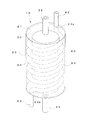
- the perspective view of the internal heat exchanger integrated accumulator which shows the 1st Embodiment of this invention
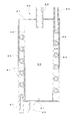
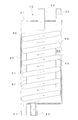
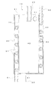
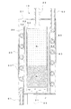
- Front sectional view of the internal heat exchanger integrated accumulator Disassembled perspective view of accumulator with integrated internal heat exchanger Front sectional view of the main part of the internal heat exchanger integrated accumulator
- Front sectional view of the internal heat exchanger integrated accumulator Front sectional view of the internal heat exchanger integrated accumulator
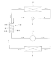
- Configuration diagram of refrigeration cycle with an internal heat exchanger integrated accumulator Partial schematic side view of a vehicle with an internal heat exchanger integrated accumulator Partial schematic side view of a vehicle equipped with a conventional internal heat exchanger integrated accumulator
- the perspective view of the internal heat exchanger integrated accumulator which shows the 2nd Embodiment of this invention.
- FIGS. 1 to 8 show a first embodiment of the present invention, which shows an aluminum internal heat exchanger integrated accumulator used in a vehicle air conditioner.
- the internal heat exchanger integrated accumulator 10 of this embodiment is provided in a cylindrical outer member 20 extending in the vertical direction, a cylindrical inner member 30 disposed in the outer member 20, and the inner member 30.
- the heat exchange chambers 50 are partitioned from each other in the radial direction of the outer member 20 via the inner member 30.
- the outer member 20 is formed in a vertically long cylindrical shape having an upper end opened, and the upper end is closed by a circular upper surface plate 21.
- the upper surface plate 21 is provided with an inflow pipe 22 through which a low-temperature refrigerant flows.
- the inflow pipe 22 passes through the center of the upper surface plate 21 and extends vertically in and out of the outer member 20.
- the upper surface plate 21 is provided with a hole 21 a that passes through one end side of the heat exchange pipe 60, and the hole 21 a is disposed on the peripheral side of the upper surface plate 21.
- the bottom surface of the outer member 20 is provided with an outflow pipe 23 through which the low-temperature refrigerant flows out.
- the outflow pipe 23 extends downward from the bottom surface of the outer member 20.
- a hole 20 a through which the other end of the heat exchange pipe 60 is inserted is provided on the bottom surface of the outer member 20, and the hole 20 a is disposed on the peripheral side of the bottom surface of the outer member 20.
- the inner member 30 is formed in a vertically long cylindrical shape having an outer diameter smaller than that of the outer member 20, and the upper end and the lower end thereof are opened.
- the inner member 30 is disposed concentrically with the outer member 20 so as to have a uniform circumferential distance between the outer peripheral surface of the inner member 30 and the inner peripheral surface of the outer member 20, and the lower end thereof is joined to the bottom surface of the outer member 20. ing.
- the inner member 30 is formed such that the upper end is positioned lower than the upper surface plate 21 of the outer member 20, and a gap is formed between the upper end of the inner member 30 and the upper surface plate 21 of the outer member 20.
- the outflow pipe 23 provided on the bottom surface of the outer member 20 is disposed between the inner member 30 and the outer member 20.
- the inner member 30 is provided with an oil outflow hole 31 through which lubricating oil flows out.
- the oil outflow hole 31 is disposed on the lower end side of the peripheral surface of the inner member 30.
- the accumulator chamber 40 is a space surrounded by the inner peripheral surface of the inner member 30 and the bottom surface of the outer member 20, and stores liquid low-temperature refrigerant flowing from the inflow pipe 22.
- the lower end side of the inflow pipe 22 is disposed so as to extend from the center in the radial direction of the inner member 30 into the accumulator chamber 40.
- the internal heat exchange chamber 50 includes a space between the outer member 20 and the inner member 30 and circulates a gaseous low-temperature refrigerant flowing from the inflow pipe 22.
- the heat exchange pipe 60 is formed so as to extend spirally in the circumferential direction of the outer member 20 and the inner member 30 from the upper end side to the lower end side of the internal heat exchange chamber 50, and the outer member 20 is formed on the lower end side thereof.
- a straight inflow pipe portion 61 extending through the bottom surface of the outer member 20 and extending outward is formed at the upper end of the straight inflow pipe portion 61 extending through the upper surface plate 21 of the outer member 20. Is formed.
- the spiral portion 63 of the heat exchange pipe 60 is disposed between the outer member 20 and the inner member 30, and is disposed on the inner peripheral surface of the outer member 20 and the outer peripheral surface of the inner member 30 so as to wind the inner member 30. As shown in FIG. 4, the contact portion between the outer member 20 and the inner member 30 is joined over the circumferential direction of the outer member 20 and the inner member 30 by brazing 60a.
- a spiral portion 63 of the heat exchange pipe 60 is disposed in the internal heat exchange chamber 50, and a spiral refrigerant flow passage 51 is formed in the internal heat exchange chamber 60 by the spiral portion 63 of the heat exchange pipe 60. . That is, the refrigerant flow passage 51 is formed between the spiral portion 63 of the heat exchange pipe 60 and the peripheral surfaces of the outer member 20 and the inner member 30, and the low-temperature refrigerant flowing from above the inner heat exchange chamber 50
- the outside of the heat exchange pipe 60 flows along the spiral portion 63 of the heat exchange pipe 60 and flows out from the lower end of the internal heat exchange chamber 50 to the outside through the outflow pipe 23.
- the internal heat exchanger integrated accumulator 10 configured as described above is used in the refrigeration cycle shown in FIG. 7, and a carbon dioxide refrigerant is used as a refrigerant in the refrigeration cycle. That is, in the internal heat exchanger integrated accumulator 10, the refrigerant discharge side of the evaporator 2 is connected to the inflow pipe 22, and the refrigerant suction side of the compressor 1 is connected to the outflow pipe 23.
- the refrigerant suction side of the expansion valve 4 is connected to the outflow pipe portion 61 of the heat exchange pipe 60, and the refrigerant discharge side of the gas cooler 3 is connected to the inflow pipe portion 62 of the heat exchange pipe 60.
- low-temperature refrigerant low-pressure refrigerant
- high-temperature refrigerant high-pressure refrigerant
- the high-temperature refrigerant flowing through the heat exchange pipe 60 becomes a low-temperature refrigerant through the expansion valve 4 and flows into the evaporator 2, absorbs heat from the external air by the evaporator 2, then flows into the accumulator chamber 30, and from the accumulator chamber 30 to the internal heat exchange chamber. After 50, it is sucked into the compressor 1.
- the gas-liquid mixed low-temperature refrigerant flows into the accumulator chamber 30 from the inflow pipe 22, and the gaseous low-temperature refrigerant R 1, liquid low-temperature refrigerant R 2, and lubricating oil J are sequentially supplied from above.
- the gas and liquid are separated by the accumulation, and only the gaseous low-temperature refrigerant R 1 flows out from the upper end of the accumulator chamber 30 to the internal heat exchange chamber 50.
- the low-temperature refrigerant that has flowed into the internal heat exchange chamber 50 flows through the refrigerant flow passage 51 from the upper side to the lower side of the internal heat exchange chamber 50 and flows out from the outflow pipe 23 to the outside.
- the low-temperature refrigerant in the internal heat exchange chamber 50 flows through the spiral refrigerant flow passage 51 along the heat exchange pipe 60, the high-temperature refrigerant in the heat exchange pipe 60 and the low-temperature refrigerant in the refrigerant flow passage 51. Heat is efficiently exchanged with the refrigerant. Further, the lubricating oil J collected in the lower part of the accumulator chamber 30 flows out from the oil outflow hole 31 to the bottom of the internal heat exchange chamber 50 and flows out from the outflow pipe 23 together with the low-temperature refrigerant.
- the high-temperature refrigerant flowing from the inflow pipe portion 61 into the heat exchange pipe 60 of the internal heat exchange chamber 50 flows through the spiral portion 63 of the heat exchange pipe 60 while flowing through the refrigerant flow path. After radiating heat to the 51 gaseous low-temperature refrigerant, it flows out from the outflow pipe portion 62 to the outside. At that time, the low-temperature refrigerant circulates in the internal heat exchange chamber 50 from the upper side to the lower side, and the high-temperature refrigerant flows in the heat exchange pipe 60 from the lower side to the upper side. The flow of the refrigerant and the high-temperature refrigerant becomes an opposite flow.
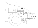
- the internal heat exchanger integrated accumulator 10 is installed in the engine room of the vehicle S as shown in FIG. At this time, since the outflow side of the high-temperature refrigerant and the inflow side of the low-temperature refrigerant are arranged on the upper end side of the outer member 20, the air inside the vehicle via the high-temperature refrigerant outflow side pipe 10a and the low-temperature refrigerant inflow side pipe 10b. It is connected to the evaporator 2 in the harmony unit 8 with the shortest distance.
- the refrigerant outflow side of the compressor 1 and the refrigerant outflow side of the gas cooler 3 are arranged in the lower part of the engine room, but the high temperature refrigerant inflow side and the low temperature refrigerant outflow side of the accumulator 10 are on the lower end side of the outer member 20. Since it is arranged, it is connected to the compressor 1 and the gas cooler 3 through the shortest distance via the high-temperature refrigerant inflow pipe 10c and the low-temperature refrigerant outflow pipe 10d. That is, as shown in FIG.
- the internal heat exchanger integrated accumulator 9 has the high-temperature refrigerant inflow side and outflow side and the low-temperature refrigerant inflow side and outflow side all at the upper end. Therefore, the outflow side of the high-temperature refrigerant and the inflow side of the low-temperature refrigerant are at the shortest distance from the evaporator 2 in the air conditioning unit 8 inside the vehicle via the outflow-side pipe 9a of the high-temperature refrigerant and the inflow-side pipe 9b of the low-temperature refrigerant.
- the high-temperature refrigerant inflow side and the low-temperature refrigerant outflow side of the accumulator 9 are connected to each other through the high-temperature refrigerant inflow pipe 9c and the low-temperature refrigerant outflow pipe 9d. And the refrigerant outflow side of the gas cooler 3. Therefore, the length of the pipe is longer than that of the present embodiment by the amount corresponding to the rising portion H1 of the high temperature refrigerant inflow side piping 9c and the rising portion H2 of the low temperature refrigerant outflow side piping 9d.
- the heat exchange pipe 60 is formed between the outer member 20 and the inner member 30 so as to extend spirally in the circumferential direction of the outer member 20 and the inner member 30, and heat exchange is performed. Since the refrigerant flow passage 51 that circulates the low-temperature refrigerant is formed between the spiral portions 63 of the pipe 60, the heat exchange pipe 60 can be formed with a sufficient length, and the low-temperature refrigerant can be moved along the heat exchange pipe 60. The spiral refrigerant flow passage 51 can be circulated.
- the low-temperature refrigerant and the heat exchange pipe 60 can sufficiently exchange heat, and the heat exchange pipe 60 to the low-temperature refrigerant can be exchanged.
- the heat dissipation effect can be enhanced.
- the low-temperature refrigerant in the refrigerant flow passage 51 and the high-temperature refrigerant in the heat exchange pipe 60 are circulated in opposite directions, the flows of the low-temperature refrigerant and the high-temperature refrigerant in the internal heat exchange chamber 50 face each other.
- the heat exchange efficiency between the low-temperature refrigerant and the high-temperature refrigerant is extremely advantageous.
- the outer member 20, the inner member 30, and the heat exchange pipe 60 are made of aluminum, brazing can be performed and strength can be improved. That is, since the heat exchange pipe 60 is brazed to the inner peripheral surface of the outer member 20 and the outer peripheral surface of the inner member 30 in the circumferential direction of the outer member 20 and the inner member 30, the outer member 20, the inner member 30, and the heat exchange The pipe 60 can be firmly joined, and the strength of the entire accumulator can be increased. Thereby, even if the plate thickness of the outer member 20 and the inner member 30 is reduced, sufficient strength can be ensured, and the weight can be reduced by reducing the thickness of the member.
- the high temperature refrigerant outflow side and the low temperature refrigerant inflow side are arranged on the upper end side of the outer member 20, and the high temperature refrigerant inflow side and the low temperature refrigerant outflow side are arranged on the lower end side of the outer member 20. Even when the refrigerant outflow side of the gas cooler 3 and the refrigerant outflow side of the gas cooler 3 are arranged in the lower part of the engine room, the high-temperature refrigerant inflow pipe 10c and the low-temperature refrigerant outflow pipe 10d are connected to the compressor 1 and the gas cooler 3 with the shortest distance. It is possible to reduce the cost and pressure loss by shortening the piping.
- FIG. 10 shows a second embodiment of the present invention, and the same components as those in the first embodiment are denoted by the same reference numerals.
- the inner member 30 is formed so that the upper end is positioned lower than the upper surface plate 21 of the outer member 20, and the low-temperature refrigerant is interposed between the upper end of the inner member 30 and the upper surface plate 21 of the outer member 20.
- the inner member 70 of the present embodiment is formed to have the same height as the outer member 20, and the upper end of the inner member 70 is joined to the upper surface plate 21.
- An outflow hole 71 through which the low-temperature refrigerant in the accumulator chamber 30 flows out to the internal heat exchange chamber 50 is provided on the upper side surface of the inner member 70.
- 11 and 12 show a third embodiment of the present invention, and the same reference numerals are given to the same components as those in the first embodiment.
- the spiral portions 63 of the heat exchange pipe 60 are shown at regular intervals.
- the heat exchange pipe 80 of the present embodiment is provided between the inflow pipe portion 81 and the outflow pipe portion 82.
- the interval P between the spiral portions 83 is formed so that the downstream side is gradually wider than the upstream side in the circulation direction of the high-temperature refrigerant.
- the downstream side of the refrigerant cross-sectional area of the refrigerant flow passage 51 of the low-temperature refrigerant formed between the spiral portions 83 of the heat exchange pipe 80 is gradually larger than the upstream side in the refrigerant flow direction. Even if the volume is increased by being heated by the exchange pipe 80, there is an advantage that the pressure loss of the refrigerant flow passage 51 can be suppressed.
- the flow passage cross-sectional area of the heat exchange pipe 80 is S1
- the flow passage cross-sectional area of the refrigerant flow passage 51 is S2
- the ratio of the flow passage cross-sectional areas is S1: S2.
- the refrigerant flow passage 51 is formed so that S2 becomes 5 or more when S1 is 4. That is, the ratio S1: S2 of the flow path cross-sectional area of the portion where the interval P of the spiral portion 83 is the smallest (the most upstream side of the refrigerant flow passage 51) is 4: 5, and as it goes to the downstream side of the refrigerant flow passage 51.
- the flow passage cross-sectional area S2 of the refrigerant flow passage 51 is formed so as to gradually increase.
- the flow passage sectional area S2 of the refrigerant flow passage 51 becomes larger than the flow passage sectional area of the heat exchange pipe 80 with respect to S1, so that the flow amount of the low temperature refrigerant with respect to the high temperature refrigerant in the internal heat exchange chamber 50 is sufficiently increased.
- the high-temperature refrigerant in the heat exchange pipe 80 and the low-temperature refrigerant in the refrigerant flow passage 51 can always exchange heat efficiently.
- the configuration in which the refrigerant flow passage 51 is formed so that S2 is 5 or more when the ratio of the channel cross-sectional area is S1: S2 and S1 is 4, can be applied to other embodiments. it can.
- FIG. 13 shows a fourth embodiment of the present invention, and the same components as those in the first embodiment are denoted by the same reference numerals.
- a heat insulating layer 32 is provided between the accumulator chamber 40 and the heat exchange pipe 60, and the heat insulating layer 32 is formed by applying a well-known heat insulating paint to the inner surface of the inner member 30.
- the heat insulating layer 32 insulates between the accumulator chamber 40 and the heat exchange pipe 60, so that the liquid low-temperature refrigerant R 2 ⁇ stored in the accumulator chamber 40 evaporates by heating the heat exchange pipe 60. Therefore, the liquid low-temperature refrigerant R2 can be reliably stored in the accumulator chamber 40.
- the heat of the high-temperature refrigerant in the heat exchange pipe 60 is not taken away by the low-temperature refrigerant in the accumulator chamber 40, the low-temperature refrigerant in the refrigerant flow passage 51 of the internal heat exchange chamber 50 is sufficiently heated by the high-temperature refrigerant.
- the heat exchange efficiency of the internal heat exchange chamber 50 is not lowered.
- the heat insulating paint is used for the heat insulating layer 32, the heat insulating layer 32 can be easily formed by applying the heat insulating paint to the inner surface of the inner member 30, and the productivity can be improved.
- FIG. 14 shows a fifth embodiment of the present invention, in which components equivalent to those in the first embodiment are denoted by the same reference numerals.
- This embodiment is another embodiment in which a heat insulating layer is provided between the accumulator chamber 40 and the heat exchange pipe 60. That is, the inner member 30 of the present embodiment is formed by inner and outer double cylindrical members 33 and 34 having a gap, and a heat insulating layer 35 made of an air layer is formed between the cylindrical members 33 and 34. As a result, as in the fourth embodiment, the effect of the heat insulating layer 35 can be obtained, and the heat insulating layer 35 can be formed only by the cylindrical members 33 and 34. Therefore, a common material ( Aluminum) can be used, and processing and assembly can be easily performed.
- a common material Aluminum
- FIG. 15 shows a sixth embodiment of the present invention, and the same components as those in the first embodiment are denoted by the same reference numerals.
- the internal heat exchanger integrated accumulator 10 of this embodiment is provided in a cylindrical outer member 90 extending in the vertical direction, a cylindrical inner member 100 disposed in the outer member 90, and the inner member 100.
- the heat exchange chambers 120 are partitioned from each other in the radial direction of the outer member 90 via the inner member 100.
- the outer member 90 is formed in a vertically long cylindrical shape having an upper end opened, and the upper end is closed by a circular upper surface plate 91.
- the upper surface plate 21 is provided with an inflow pipe 92 through which a low-temperature refrigerant flows.
- the inflow pipe 92 extends through the center of the upper surface plate 91 in and out of the outer member 90.
- An outflow pipe 93 through which the low-temperature refrigerant flows out is provided on the lower side surface of the outer member 90, and the outflow pipe 93 extends from the side surface of the outer member 90 to the outside.
- the inner member 100 is formed in a vertically long cylindrical shape having an outer diameter smaller than that of the outer member 90 and has an upper end opened.
- the inner member 100 is arranged concentrically with the outer member 90 so as to have a uniform circumferential distance between the outer peripheral surface and the inner peripheral surface of the outer member 20, and the lower end side penetrates the bottom surface of the outer member 90. Then, it extends below the outer member 90.
- the inner member 100 is formed such that the upper end is positioned lower than the upper surface plate 91 of the outer member 90, and a gap is formed between the upper end of the inner member 100 and the upper surface plate 91 of the outer member 20. .
- the outflow pipe 93 of the outer member 90 extends downward from the outer member 90, bends in the lateral direction, extends to the lower side of the inner member 100, and is further bent downward.
- An oil outflow pipe 101 for outflowing lubricating oil is provided on the bottom surface of the inner member 100, and the oil outflow pipe 101 is connected to the outflow pipe 93.
- the accumulator chamber 110 is a space surrounded by the inner peripheral surface of the inner member 100 and the bottom surface of the outer member 90, and stores liquid low-temperature refrigerant flowing from the inflow pipe 92.
- the lower end side of the inflow pipe 92 is disposed so as to extend from the center in the radial direction of the inner member 100 into the accumulator chamber 110.
- the internal heat exchange chamber 120 is a space between the outer member 90 and the inner member 100 and circulates a gaseous low-temperature refrigerant flowing from the inflow pipe 92.
- the accumulator chamber 110 is formed longer than the internal heat exchange chamber 120. .
- the heat exchange pipe 130 is formed so as to extend spirally in the circumferential direction of the outer member 90 and the inner member 100 from the upper end side to the lower end side of the internal heat exchange chamber 120, and the outer member 90 is disposed on the lower end side thereof.
- a straight inflow pipe portion 131 extending through the bottom surface of the outer member 90 is formed at the upper end side thereof, and a straight outflow pipe portion 132 extending through the upper surface plate 91 of the outer member 90 to the outside. Is formed.
- the spiral portion 133 of the heat exchange pipe 130 is disposed between the outer member 90 and the inner member 100, and is disposed on the inner peripheral surface of the outer member 90 and the outer peripheral surface of the inner member 100 so as to wind the inner member 100.
- the outer member 90 and the inner member 100 are joined together in the circumferential direction of the outer member 90 and the inner member 100 by brazing.
- a spiral portion 133 of the heat exchange pipe 130 is disposed in the internal heat exchange chamber 120, and a spiral refrigerant flow passage 121 is formed in the internal heat exchange chamber 130 by the spiral portion 133 of the heat exchange pipe 130. . That is, the refrigerant flow passage 121 is formed between the spiral portion 133 of the heat exchange pipe 130 and the peripheral surfaces of the outer member 90 and the inner member 100, and the low-temperature refrigerant flowing from above the inner heat exchange chamber 120
- the heat exchange pipe 130 is circulated along the spiral portion 133 of the heat exchange pipe 130 and flows out from the lower end of the internal heat exchange chamber 120 through the outflow pipe 93.
- the spiral portion 133 of the heat exchange pipe 130 is not disposed on the lower side of the accumulator chamber 110.
- the liquid low-temperature refrigerant R2 stored in the lower side of the accumulator chamber 110 does not evaporate due to the heating of the heat exchange pipe 130, and the liquid low-temperature refrigerant R2 ⁇ ⁇ is reliably stored in the accumulator chamber 110. I can keep it.
- the heat of the high-temperature refrigerant in the heat exchange pipe 130 is not taken away by the liquid low-temperature refrigerant R2 in the accumulator chamber 110, the low-temperature refrigerant in the refrigerant flow passage 121 of the internal heat exchange chamber 120 is removed by the high-temperature refrigerant.
- the heat can be sufficiently heated and the heat exchange efficiency of the internal heat exchange chamber 120 is not lowered.
- SYMBOLS 10 Internal heat exchanger integrated accumulator, 20 ... Outer member, 30 ... Inner member, 32 ... Thermal insulation layer, 33, 34 ... Cylindrical member, 35 ... Thermal insulation layer, 40 ... Accumulator chamber, 50 ... Internal heat exchange chamber, 51 ... Refrigerant flow path, 60 ... Heat exchange pipe, 63 ... Spiral part, 70 ... Inner member, 80 ... Heat exchange pipe, 83 ... Spiral part, 90 ... Outer member, 100 ... Inner member, 110 ... Accumulator chamber, DESCRIPTION OF SYMBOLS 120 ... Internal heat exchange chamber, 121 ... Refrigerant flow path, 130 ... Heat exchange pipe, 133 ... Spiral part.
Landscapes
- Engineering & Computer Science (AREA)
- Physics & Mathematics (AREA)
- Mechanical Engineering (AREA)
- Thermal Sciences (AREA)
- General Engineering & Computer Science (AREA)
- Air-Conditioning For Vehicles (AREA)
- Heat-Exchange Devices With Radiators And Conduit Assemblies (AREA)
Abstract
【課題】低温冷媒と熱交換パイプとの熱交換効率を向上させることのできる内部熱交換器一体型アキュムレータ及びこれを用いた冷凍サイクルを提供する。 【解決手段】熱交換パイプ60を外側部材20と内側部材30との間に外側部材20及び内側部材30の周方向に螺旋状に延びるように形成するとともに、熱交換パイプ60の螺旋状部分63の間に低温冷媒を流通する冷媒流通路51を形成したので、熱交換パイプ60を十分な長さに形成することができるとともに、低温冷媒を熱交換パイプ60に沿った螺旋状の冷媒流通路51を流通させることができ、内部熱交換室50内における低温冷媒の流通距離を長くすることができる。この場合、冷媒流通路51内の低温冷媒と熱交換パイプ60内の高温冷媒とを互いに反対方向に流通させるようにしたので、内部熱交換室50内における低温冷媒と高温冷媒の流れが対向流となる。
Description
本発明は、車両用空気調和装置の冷凍回路に用いられる内部熱交換器一体型アキュムレータ及びこれを用いた冷凍サイクルに関するものである。
一般に、乗用車等の車両に用いられる空気調和装置は、図16に示すように、圧縮機1、エバポレータ2、ガスクーラ3、膨張弁4、アキュムレータ5を冷媒配管で接続することにより冷凍サイクルを構成し、圧縮機1によって冷媒を冷凍回路に循環させるようになっている。この場合、エバポレータ2から流出した低温冷媒とガスクーラ3から流出した高温冷媒とを内部熱交換器6によって熱交換することにより、冷凍効率を向上させるようにしたものが知られている(例えば、特許文献1参照)。
また、前記アキュムレータ5と内部熱交換器6はそれぞれ別部品からなるが、これらを一体に構成したものも知られている(例えば、特許文献2または3参照)。図17に示す内部熱交換器一体型アキュムレータ7は、円筒状の本体7a内を仕切壁7bによって上下二つの空間7c,7dに仕切り、上方の空間7c内に熱交換パイプ7eを配置したもので、外部から下方の空間内に流入した低温冷媒を気液分離させた後、仕切壁7bの連通孔7fを介して気体状の低温冷媒を上方の空間内7cに流入させるとともに、上方の空間7c内を流通する低温冷媒と熱交換パイプ7eを流通する高温冷媒とを熱交換させるようにしている。
しかしながら、前記内部熱交換器一体型アキュムレータ7では、円筒状の本体7a内を仕切壁7bにより上下二つの空間に仕切るようにしているため、上方の空間7cの高さ寸法を大きくすることができず、仕切壁7bの連通孔7fから上方の空間7cの冷媒出口までの冷媒流通距離が短くなる。このため、上方の空間7c内で低温冷媒を熱交換パイプ7eと十分に熱交換させることができず、熱交換パイプ7eから低温冷媒への放熱効果が低いという問題点があった。また、前記従来例では、熱交換パイプ7eを上方の空間7c内に配置しているにすぎないため、熱交換パイプ7eは周囲の低温冷媒としか熱交換することができず、このような構成によっても熱交換パイプ7eから低温冷媒への放熱効果が低いという問題点があった。
本発明は前記課題に鑑みてなされたものであり、その目的とするところは、低温冷媒と熱交換パイプとの熱交換効率を向上させることのできる内部熱交換器一体型アキュムレータ及びこれを用いた冷凍サイクルを提供することにある。
本発明の内部熱交換器一体型アキュムレータは、前記目的を達成するために、上下方向に延びる円筒状の外側部材と、外側部材内に配置された円筒状の内側部材と、内側部材内に設けられたアキュムレータ室と、外側部材と内側部材との間に設けられた内部熱交換室と、内部熱交換室内に配置された熱交換パイプとを備え、外部からアキュムレータ室に流入した低温冷媒をアキュムレータ室内で気液分離させた後、気体状の低温冷媒を内部熱交換室内に流入させるとともに、内部熱交換室内を流通する低温冷媒と熱交換パイプを流通する高温冷媒とを熱交換させるようにした内部熱交換器一体型アキュムレータであって、前記外側部材、内側部材及び熱交換パイプをアルミニウムによって形成し、熱交換パイプを外側部材と内側部材との間に外側部材及び内側部材の周方向に螺旋状に延びるように形成するとともに、熱交換パイプを外側部材の内周面と内側部材の外周面に外側部材及び内側部材の周方向に亘ってろう付けし、熱交換パイプの螺旋状部分の間に熱交換パイプに沿って低温冷媒を流通する螺旋状の冷媒流通路を形成し、冷媒流通路内の低温冷媒と熱交換パイプ内の高温冷媒とを互いに反対方向に流通させるように構成している。
これにより、熱交換パイプが外側部材と内側部材との間に外側部材及び内側部材の周方向に螺旋状に延びるように形成されるとともに、熱交換パイプの螺旋状部分の間に低温冷媒を流通する螺旋状の冷媒流通路が形成されることから、熱交換パイプが十分な長さに形成されるとともに、低温冷媒が熱交換パイプに沿った螺旋状の冷媒流通路を流通することから、内部熱交換室内における低温冷媒の流通距離が長くなる。この場合、冷媒流通路内の低温冷媒と熱交換パイプ内の高温冷媒とが互いに反対方向に流通することから、内部熱交換室内における低温冷媒と高温冷媒の流れが対向流となる。また、少なくとも外側部材、内側部材及び熱交換パイプがアルミニウムによって形成されることから、ろう付けが可能になり、熱交換パイプが外側部材の内周面と内側部材の外周面に外側部材及び内側部材の周方向に亘ってろう付けされることから、外側部材、内側部材及び熱交換パイプがろう付けによって強固に接合される。
本発明によれば、熱交換パイプを十分な長さに形成することができるとともに、内部熱交換室内における低温冷媒の流通距離を長くすることができるので、低温冷媒と熱交換パイプとを十分に熱交換させることができ、熱交換パイプから低温冷媒への放熱効果を高めることができる。この場合、内部熱交換室内における低温冷媒と高温冷媒の流れを対向流とすることができるので、低温冷媒と高温冷媒との熱交換効率の向上に極めて有利である。また、外側部材、内側部材及び熱交換パイプをろう付けによって強固に接合することができるので、アキュムレータ全体の強度を高めることができる。これにより、外側部材と内側部材の板厚を薄くしても十分な強度を確保することができるので、部材の薄肉化による軽量化を図ることができる。
図1乃至図8は本発明の第1の実施形態を示すもので、車両用空気調和装置に用いられるアルミニウム製の内部熱交換器一体型アキュムレータを示すものである。
本実施形態の内部熱交換器一体型アキュムレータ10は、上下方向に延びる円筒状の外側部材20と、外側部材20内に配置された円筒状の内側部材30と、内側部材30内に設けられたアキュムレータ室40と、外側部材20と内側部材30との間に設けられた内部熱交換室50と、内部熱交換室50内に配置された熱交換パイプ60とから構成され、アキュムレータ室30と内部熱交換室50は互いに内側部材30を介して外側部材20の径方向に仕切られている。
外側部材20は、上端を開口した縦長円筒状に形成され、その上端は円形の上面板21によって閉塞されている。上面板21には低温冷媒を流入する流入パイプ22が設けられ、流入パイプ22は上面板21の中央を貫通して外側部材20の内外に上下方向に延びている。また、上面板21には熱交換パイプ60の一端側を挿通する孔21aが設けられ、孔21aは上面板21の周縁側に配置されている。外側部材20の底面には低温冷媒を流出する流出パイプ23が設けられ、流出パイプ23は外側部材20の底面から下方に延出している。また、外側部材20の底面には熱交換パイプ60の他端側を挿通する孔20aが設けられ、孔20aは外側部材20の底面の周縁側に配置されている。
内側部材30は、外側部材20よりも外径の小さい縦長円筒状に形成され、その上端及び下端をそれぞれ開口している。内側部材30は、その外周面と外側部材20の内周面との間に周方向均一の間隔を有するように外側部材20と同心円状に配置され、その下端は外側部材20の底面に接合されている。この場合、内側部材30は上端が外側部材20の上面板21よりも低い位置になるように形成され、内側部材30の上端と外側部材20の上面板21との間に隙間が形成されている。また、外側部材20の底面に設けられた流出パイプ23は内側部材30と外側部材20との間に配置されている。内側部材30には潤滑油を流出するためのオイル流出孔31が設けられ、オイル流出孔31は内側部材30の周面の下端側に配置されている。
アキュムレータ室40は、内側部材30の内周面と外側部材20の底面によって囲まれた空間からなり、流入パイプ22から流入する液体状の低温冷媒を貯溜するようになっている。アキュムレータ室40の上端側には流入パイプ22の下端側が内側部材30の径方向中央からアキュムレータ室40内に延びるように配置されている。
内部熱交換室50は、外側部材20と内側部材30との間の空間からなり、流入パイプ22から流入する気体状の低温冷媒を流通するようになっている。
熱交換パイプ60は、内部熱交換室50の上端側から下端側に亘って外側部材20及び内側部材30の周方向に螺旋状に延びるように形成されるとともに、その下端側には外側部材20の底面を貫通して外部に延出する直線状の流入管部61が形成され、その上端側には外側部材20の上面板21を貫通して外部に延出する直線状の流出管部62が形成されている。熱交換パイプ60の螺旋状部分63は外側部材20と内側部材30との間に配置されるとともに、内側部材30を巻回するように外側部材20の内周面と内側部材30の外周面に接触しており、図4に示すように外側部材20と内側部材30との接触部分をろう付け60aにより外側部材20及び内側部材30の周方向に亘って接合されている。
内部熱交換室50内には熱交換パイプ60の螺旋状部分63が配置され、熱交換パイプ60の螺旋状部分63によって内部熱交換室60内に螺旋状の冷媒流通路51が形成されている。即ち、冷媒流通路51は、熱交換パイプ60の螺旋状部分63の間と外側部材20及び内側部材30の周面との間に形成され、内部熱交換室50の上方から流入した低温冷媒が熱交換パイプ60の外部を熱交換パイプ60の螺旋状部分63に沿って流通し、内部熱交換室50の下端から流出パイプ23を介して外部に流出するようになっている。
以上のように構成された内部熱交換器一体型アキュムレータ10は、図7に示す冷凍サイクルに用いられ、冷凍サイクルの冷媒には二酸化炭素冷媒が使用される。即ち、内部熱交換器一体型アキュムレータ10は、流入パイプ22にエバポレータ2の冷媒吐出側が接続され、流出パイプ23に圧縮機1の冷媒吸入側が接続される。また、熱交換パイプ60の流出管部61には膨張弁4の冷媒吸入側が接続され、熱交換パイプ60の流入管部62にはガスクーラ3の冷媒吐出側が接続されている。
前記冷凍サイクルでは、低温冷媒(低圧冷媒)が図中実線矢印で示すように流通し、高温冷媒(高圧冷媒)が図中破線矢印で示すように流通する。即ち、圧縮機1から吐出した高温冷媒がガスクーラ3に流入し、ガスクーラ3で外部空気に放熱した後、内部熱交換室50内の熱交換パイプ60に流入する。熱交換パイプ60を流通した高温冷媒は膨張弁4を経て低温冷媒となり、エバポレータ2に流入し、エバポレータ2で外部空気から吸熱した後、アキュムレータ室30に流入し、アキュムレータ室30から内部熱交換室50を経て圧縮機1に吸入される。
図5の実線矢印で示すように、アキュムレータ室30には気液混合の低温冷媒が流入パイプ22から流入し、気体状の低温冷媒R1 、液体状の低温冷媒R2 、潤滑油Jが上方から順に溜まることにより気液分離され、気体状の低温冷媒R1 のみがアキュムレータ室30の上端から内部熱交換室50に流出する。内部熱交換室50に流入した低温冷媒は、内部熱交換室50の上方から下方に向かって冷媒流通路51内を流通し、流出パイプ23から外部に流出する。その際、内部熱交換室50内の低温冷媒は、熱交換パイプ60に沿った螺旋状の冷媒流通路51を流通することから、熱交換パイプ60内の高温冷媒と冷媒流通路51内の低温冷媒とが効率よく熱交換される。また、アキュムレータ室30の下部に溜まった潤滑油Jはオイル流出孔31から内部熱交換室50内の底部に流出し、流出パイプ23から低温冷媒と共に外部に流出する。
一方、図5の破線矢印で示すように、内部熱交換室50の熱交換パイプ60に流入管部61から流入した高温冷媒は、熱交換パイプ60の螺旋状部分63を流通しながら冷媒流通路51の気体状の低温冷媒に放熱した後、流出管部62から外部に流出する。その際、内部熱交換室50内を低温冷媒が上方から下方に向かって流通し、熱交換パイプ60内を高温冷媒が下方から上方に向かって流通することから、内部熱交換室50内における低温冷媒と高温冷媒の流れが対向流となる。
また、前記内部熱交換器一体型アキュムレータ10は、図8に示すように車両Sのエンジンルーム内に設置される。その際、高温冷媒の流出側と低温冷媒の流入側は外側部材20の上端側に配置されることから、高温冷媒の流出側配管10aと低温冷媒の流入側配管10bを介して車内側の空気調和ユニット8内のエバポレータ2に最短距離で接続される。また、圧縮機1の冷媒流出側とガスクーラ3の冷媒流出側はエンジンルーム内の下部に配置されるが、アキュムレータ10の高温冷媒の流入側と低温冷媒の流出側は外側部材20の下端側に配置されることから、高温冷媒の流入側配管10cと低温冷媒の流出側配管10dを介して圧縮機1及びガスクーラ3に最短距離で接続される。即ち、図9に示すように、従来例(例えば、特許文献3)では、内部熱交換器一体型アキュムレータ9が、高温冷媒の流入側及び流出側と低温冷媒の流入側及び流出側が全て上端に設けられているため、高温冷媒の流出側と低温冷媒の流入側は高温冷媒の流出側配管9aと低温冷媒の流入側配管9bを介して車内側の空気調和ユニット8内のエバポレータ2に最短距離で接続されるが、アキュムレータ9の高温冷媒の流入側と低温冷媒の流出側は上方に立ち上げた高温冷媒の流入側配管9cと低温冷媒の流出側配管9dを介して圧縮機1の冷媒流出側とガスクーラ3の冷媒流出側に接続される。このため、高温冷媒の流入側配管9cの立ち上げ部分H1 と低温冷媒の流出側配管9dの立ち上げ部分H2 の分だけ本実施形態よりも配管が長くなる。
このように、本実施形態によれば、熱交換パイプ60を外側部材20と内側部材30との間に外側部材20及び内側部材30の周方向に螺旋状に延びるように形成するとともに、熱交換パイプ60の螺旋状部分63の間に低温冷媒を流通する冷媒流通路51を形成したので、熱交換パイプ60を十分な長さに形成することができるとともに、低温冷媒を熱交換パイプ60に沿った螺旋状の冷媒流通路51を流通させることができる。これにより、内部熱交換室50内における低温冷媒の流通距離を長くすることができるので、低温冷媒と熱交換パイプ60とを十分に熱交換させることができ、熱交換パイプ60から低温冷媒への放熱効果を高めることができる。この場合、冷媒流通路51内の低温冷媒と熱交換パイプ60内の高温冷媒とを互いに反対方向に流通させるようにしたので、内部熱交換室50内における低温冷媒と高温冷媒の流れが対向流となり、低温冷媒と高温冷媒との熱交換効率の向上に極めて有利である。
また、少なくとも外側部材20、内側部材30及び熱交換パイプ60がアルミニウムによって形成されているので、ろう付けが可能になり、強度を向上させることができる。即ち、熱交換パイプ60を外側部材20の内周面と内側部材30の外周面に外側部材20及び内側部材30の周方向に亘ってろう付けしたので、外側部材20、内側部材30及び熱交換パイプ60を強固に接合することができ、アキュムレータ全体の強度を高めることができる。これにより、外側部材20と内側部材30の板厚を薄くしても十分な強度を確保することができるので、部材の薄肉化による軽量化を図ることができる。
更に、高温冷媒の流出側と低温冷媒の流入側を外側部材20の上端側に配置し、高温冷媒の流入側と低温冷媒の流出側を外側部材20の下端側に配置したので、圧縮機1の冷媒流出側とガスクーラ3の冷媒流出側がエンジンルーム内の下部に配置される場合でも、高温冷媒の流入側配管10cと低温冷媒の流出側配管10dを最短距離で圧縮機1及びガスクーラ3に接続することができ、配管の短縮による低コスト化と圧力損失の低減を図ることができる。
図10は本発明の第2の実施形態を示すもので、第1の実施形態と同等の構成部分には同一の符号を付して示す。
第1の実施形態では、内側部材30を上端が外側部材20の上面板21よりも低い位置になるように形成し、内側部材30の上端と外側部材20の上面板21との間に低温冷媒を流通させるようにしたものを示したが、本実施形態の内側部材70は外側部材20と同じ高さになるように形成され、内側部材70の上端を上面板21に接合されている。また、内側部材70の上部側面にはアキュムレータ室30内の低温冷媒を内部熱交換室50に流出する流出孔71が設けられている。
これにより、内側部材70の上端が上面板21に接合されるので、上面板21の接合箇所を多くすることができ、強度の向上を図ることができる。
図11及び図12は本発明の第3の実施形態を示すもので、第1の実施形態と同等の構成部分には同一の符号を付して示す。
第1の実施形態では、熱交換パイプ60の螺旋状部分63が等間隔にしたものを示したが、本実施形態の熱交換パイプ80は、流入管部81と流出管部82との間の螺旋状部分83の間隔Pが高温冷媒の流通方向上流側よりも下流側が徐々に広くなるように形成されている。
これにより、熱交換パイプ80の螺旋状部分83間に形成される低温冷媒の冷媒流通路51の流路断面積の冷媒流通方向下流側が上流側よりも徐々に大きくなることから、低温冷媒が熱交換パイプ80によって加熱されて体積が増大しても冷媒流通路51の圧力損失を抑制することができるという利点がある。
また、本実施形態では、図12に示すように熱交換パイプ80の流路断面積をS1 、冷媒流通路51の流路断面積をS2 とし、その流路断面積の比をS1 :S2 とすると、S1 を4としたときS2 が5以上になるように冷媒流通路51形成している。即ち、螺旋状部分83の間隔Pが最も小さい部分(冷媒流通路51の最も上流側)の流路断面積の比S1 :S2 を4:5とし、冷媒流通路51の下流側に向かうにしたがって冷媒流通路51の流路断面積S2 が徐々に大きくなるように形成される。
これにより、熱交換パイプ80の流路断面積をS1 に対して冷媒流通路51の流路断面積S2 が大きくなるので、内部熱交換室50内の高温冷媒に対する低温冷媒の流通量を十分に確保することができ、熱交換パイプ80の高温冷媒と冷媒流通路51の低温冷媒とを常に効率よく熱交換することができる。
尚、前述のように流路断面積の比をS1 :S2 とし、S1 を4としたときS2 が5以上になるように冷媒流通路51形成する構成は他の実施形態にも適用することができる。
図13は本発明の第4の実施形態を示すもので、第1の実施形態と同等の構成部分には同一の符号を付して示す。
本実施形態では、アキュムレータ室40と熱交換パイプ60との間に断熱層32が設けられ、断熱層32は周知の断熱塗料を内側部材30の内面に塗布することによって形成されている。これにより、断熱層32によってアキュムレータ室40と熱交換パイプ60との間が断熱されることから、アキュムレータ室40内に貯溜された液体状の低温冷媒R2 が熱交換パイプ60の加熱によって蒸発することがなく、アキュムレータ室40内に液体状の低温冷媒R2 を確実に貯溜しておくことができる。また、熱交換パイプ60内の高温冷媒の熱がアキュムレータ室40内の低温冷媒に奪われることがないので、高温冷媒によって内部熱交換室50の冷媒流通路51内の低温冷媒を十分に加熱することができ、内部熱交換室50の熱交換効率を低下させることがないという利点がある。更に、断熱層32に断熱塗料を用いているので、内側部材30の内面に断熱塗料を塗布することによって断熱層32を容易に形成することができ、生産性の向上を図ることができる。
図14は本発明の第5の実施形態を示すもので、第1の実施形態と同等の構成部分には同一の符号を付して示す。
本実施形態は、アキュムレータ室40と熱交換パイプ60との間に断熱層を設けた他の実施形態である。即ち、本実施形態の内側部材30は互いに隙間を有する内外二重の円筒状部材33,34によって形成され、各円筒状部材33,34間に空気層からなる断熱層35が形成されている。これにより、第4の実施形態と同様、断熱層35による効果を得ることができるとともに、円筒状部材33,34のみで断熱層35を形成することができるので、他の部品と共通の材料(アルミニウム)を用いることができ、加工及び組立を容易に行うことができる。
図15は本発明の第6の実施形態を示すもので、第1の実施形態と同等の構成部分には同一の符号を付して示す。
本実施形態の内部熱交換器一体型アキュムレータ10は、上下方向に延びる円筒状の外側部材90と、外側部材90内に配置された円筒状の内側部材100と、内側部材100内に設けられたアキュムレータ室110と、外側部材90と内側部材100との間に設けられた内部熱交換室120と、内部熱交換室120内に配置された熱交換パイプ130とから構成され、アキュムレータ室110と内部熱交換室120は互いに内側部材100を介して外側部材90の径方向に仕切られている。
外側部材90は、上端を開口した縦長円筒状に形成され、その上端は円形の上面板91によって閉塞されている。上面板21には低温冷媒を流入する流入パイプ92が設けられ、流入パイプ92は上面板91の中央を貫通して外側部材90の内外に上下方向に延びている。外側部材90の下部側面には低温冷媒を流出する流出パイプ93が設けられ、流出パイプ93は外側部材90の側面から外部に延出している。
内側部材100は、外側部材90よりも外径の小さい縦長円筒状に形成され、その上端を開口している。内側部材100は、その外周面と外側部材20の内周面との間に周方向均一の間隔を有するように外側部材90と同心円状に配置され、その下端側は外側部材90の底面を貫通して外側部材90の下方に延出している。この場合、内側部材100は上端が外側部材90の上面板91よりも低い位置になるように形成され、内側部材100の上端と外側部材20の上面板91との間に隙間が形成されている。また、外側部材90の流出パイプ93は外側部材90から下方に向かって延びるとともに、横方向に屈曲して内側部材100の下方まで延び、更に下方に向かって屈曲している。内側部材100の底面には潤滑油を流出するためのオイル流出パイプ101が設けられ、オイル流出パイプ101は流出パイプ93に接続されている。
アキュムレータ室110は、内側部材100の内周面と外側部材90の底面によって囲まれた空間からなり、流入パイプ92から流入する液体状の低温冷媒を貯溜するようになっている。アキュムレータ室110の上端側には流入パイプ92の下端側が内側部材100の径方向中央からアキュムレータ室110内に延びるように配置されている。
内部熱交換室120は、外側部材90と内側部材100との間の空間からなり、流入パイプ92から流入する気体状の低温冷媒を流通するようになっている。本実施形態では、内側部材100の下端側が外側部材20の底面を貫通して外側部材90の下方に延出しているので、アキュムレータ室110が内部熱交換室120よりも下方に長く形成されている。
熱交換パイプ130は、内部熱交換室120の上端側から下端側に亘って外側部材90及び内側部材100の周方向に螺旋状に延びるように形成されるとともに、その下端側には外側部材90の底面を貫通して外部に延出する直線状の流入管部131が形成され、その上端側には外側部材90の上面板91を貫通して外部に延出する直線状の流出管部132が形成されている。熱交換パイプ130の螺旋状部分133は外側部材90と内側部材100との間に配置されるとともに、内側部材100を巻回するように外側部材90の内周面と内側部材100の外周面に接触しており、外側部材90と内側部材100との接触部分をろう付けにより外側部材90及び内側部材100の周方向に亘って接合されている。
内部熱交換室120内には熱交換パイプ130の螺旋状部分133が配置され、熱交換パイプ130の螺旋状部分133によって内部熱交換室130内に螺旋状の冷媒流通路121が形成されている。即ち、冷媒流通路121は、熱交換パイプ130の螺旋状部分133の間と外側部材90及び内側部材100の周面との間に形成され、内部熱交換室120の上方から流入した低温冷媒が熱交換パイプ130の外部を熱交換パイプ130の螺旋状部分133に沿って流通し、内部熱交換室120の下端から流出パイプ93を介して外部に流出するようになっている。
本実施形態では、アキュムレータ室110を内部熱交換室120よりも下方に長く形成したので、アキュムレータ室110の下部側には熱交換パイプ130の螺旋状部分133が配置されていない。これにより、アキュムレータ室110内の下部側に貯溜された液体状の低温冷媒R2 が熱交換パイプ130の加熱によって蒸発することがなく、アキュムレータ室110内に液体状の低温冷媒R2 を確実に貯溜しておくことができる。また、熱交換パイプ130内の高温冷媒の熱がアキュムレータ室110内の液体状の低温冷媒R2 に奪われることがないので、高温冷媒によって内部熱交換室120の冷媒流通路121内の低温冷媒を十分に加熱することができ、内部熱交換室120の熱交換効率を低下させることがないという利点がある。
10…内部熱交換器一体型アキュムレータ、20…外側部材、30…内側部材、32…断熱層、33,34…円筒状部材、35…断熱層、40…アキュムレータ室、50…内部熱交換室、51…冷媒流通路、60…熱交換パイプ、63…螺旋状部分、70…内側部材、80…熱交換パイプ、83…螺旋状部分、90…外側部材、100…内側部材、110…アキュムレータ室、120…内部熱交換室、121…冷媒流通路、130…熱交換パイプ、133…螺旋状部分。
Claims (9)
- 上下方向に延びる円筒状の外側部材と、外側部材内に配置された円筒状の内側部材と、内側部材内に設けられたアキュムレータ室と、外側部材と内側部材との間に設けられた内部熱交換室と、内部熱交換室内に配置された熱交換パイプとを備え、外部からアキュムレータ室に流入した低温冷媒をアキュムレータ室内で気液分離させた後、気体状の低温冷媒を内部熱交換室内に流入させるとともに、内部熱交換室内を流通する低温冷媒と熱交換パイプを流通する高温冷媒とを熱交換させるようにした内部熱交換器一体型アキュムレータであって、
前記外側部材、内側部材及び熱交換パイプをアルミニウムによって形成し、
熱交換パイプを外側部材と内側部材との間に外側部材及び内側部材の周方向に螺旋状に延びるように形成するとともに、
熱交換パイプを外側部材の内周面と内側部材の外周面に外側部材及び内側部材の周方向に亘ってろう付けし、
熱交換パイプの螺旋状部分の間に熱交換パイプに沿って低温冷媒を流通する螺旋状の冷媒流通路を形成し、
冷媒流通路内の低温冷媒と熱交換パイプ内の高温冷媒とを互いに反対方向に流通させるように構成した
ことを特徴とする内部熱交換器一体型アキュムレータ。 - 前記高温冷媒の流出側と低温冷媒の流入側を外側部材の上端側に配置し、
高温冷媒の流入側と低温冷媒の流出側を外側部材の下端側に配置した
ことを特徴とする請求項1記載の内部熱交換器一体型アキュムレータ。 - 前記アキュムレータ室と熱交換パイプとの間に断熱層を設けた
ことを特徴とする請求項1または2記載の内部熱交換器一体型アキュムレータ。 - 前記断熱層を断熱塗料によって形成した
ことを特徴とする請求項3記載の内部熱交換器一体型アキュムレータ。 - 前記内側部材を互いに隙間を有する内外二重の円筒状部材によって形成し、各円筒状部材間に前記断熱層を形成した
ことを特徴とする請求項3記載の内部熱交換器一体型アキュムレータ。 - 前記アキュムレータ室を内部熱交換室よりも下方に長く形成した
ことを特徴とする請求項1または2記載の内部熱交換器一体型アキュムレータ。 - 前記熱交換パイプを、高温冷媒の流通方向下流側の螺旋状部分の間隔が上流側よりも徐々に広くなるように形成した
ことを特徴とする請求項1乃至6の何れか一項記載の内部熱交換器一体型アキュムレータ。 - 前記熱交換パイプの流路断面積と前記冷媒流通路の流路断面積との比をS1 :S2 とすると、S1 を4としたときS2 が5以上になるように冷媒流通路を形成した
ことを特徴とする請求項1乃至7の何れか一項記載の内部熱交換器一体型アキュムレータ。 - 少なくとも圧縮機、ガスクーラ、膨張弁、エバポレータからなり、
請求項1乃至8の何れか一項記載の内部熱交換器一体型アキュムレータを備えた
ことを特徴とする冷凍サイクル。
Priority Applications (1)
| Application Number | Priority Date | Filing Date | Title |
|---|---|---|---|
| DE112017005621.7T DE112017005621T5 (de) | 2016-11-08 | 2017-10-20 | Energiespeicher mit integriertem internem Wärmetauscher und Kältekreislauf der denselben verwendet |
Applications Claiming Priority (2)
| Application Number | Priority Date | Filing Date | Title |
|---|---|---|---|
| JP2016218287A JP6889541B2 (ja) | 2016-11-08 | 2016-11-08 | 内部熱交換器一体型アキュムレータ及びこれを用いた冷凍サイクル |
| JP2016-218287 | 2016-11-08 |
Publications (1)
| Publication Number | Publication Date |
|---|---|
| WO2018088166A1 true WO2018088166A1 (ja) | 2018-05-17 |
Family
ID=62109701
Family Applications (1)
| Application Number | Title | Priority Date | Filing Date |
|---|---|---|---|
| PCT/JP2017/037909 Ceased WO2018088166A1 (ja) | 2016-11-08 | 2017-10-20 | 内部熱交換器一体型アキュムレータ及びこれを用いた冷凍サイクル |
Country Status (3)
| Country | Link |
|---|---|
| JP (1) | JP6889541B2 (ja) |
| DE (1) | DE112017005621T5 (ja) |
| WO (1) | WO2018088166A1 (ja) |
Cited By (2)
| Publication number | Priority date | Publication date | Assignee | Title |
|---|---|---|---|---|
| CN112519534A (zh) * | 2020-12-22 | 2021-03-19 | 苏州市活跃量子生物科技有限公司 | 一种汽车空调蓄冷节能系统 |
| CN116804502A (zh) * | 2022-12-27 | 2023-09-26 | 浙江三花智能控制股份有限公司 | 气液分离装置及热管理系统 |
Families Citing this family (5)
| Publication number | Priority date | Publication date | Assignee | Title |
|---|---|---|---|---|
| EP3757485B1 (en) * | 2018-02-24 | 2023-08-02 | Zhejiang Sanhua Intelligent Controls Co., Ltd. | Gas-liquid separator |
| CN108759202B (zh) * | 2018-07-30 | 2023-10-27 | 东莞市艾瑞科热能设备有限公司 | 一种气液分离器 |
| KR102711202B1 (ko) * | 2019-10-08 | 2024-09-30 | 한온시스템 주식회사 | 열교환기 |
| CN112432400A (zh) * | 2020-01-20 | 2021-03-02 | 浙江三花智能控制股份有限公司 | 气液分离器及热管理系统 |
| CN113514266B (zh) * | 2021-05-21 | 2022-09-27 | 中国石油大学(北京) | 低温工况下绕管式换热器内流型观测实验装置 |
Citations (10)
| Publication number | Priority date | Publication date | Assignee | Title |
|---|---|---|---|---|
| JPS52165360U (ja) * | 1976-06-07 | 1977-12-14 | ||
| JPS5417158U (ja) * | 1977-07-05 | 1979-02-03 | ||
| JP2000227289A (ja) * | 1999-02-01 | 2000-08-15 | Behr Gmbh & Co | 一体型ヘッダ・熱交換器組立体 |
| US20030121648A1 (en) * | 2001-12-28 | 2003-07-03 | Visteon Global Technologies, Inc. | Counter-flow heat exchanger with optimal secondary cross-flow |
| JP2004100974A (ja) * | 2002-09-05 | 2004-04-02 | Zexel Valeo Climate Control Corp | アキュムレータ及びこれを用いた冷凍サイクル |
| JP2004526934A (ja) * | 2001-05-24 | 2004-09-02 | ハラ・クライメート・コントロール・カナダ・インコーポレーテッド | 内部熱交換器アキュムレータ |
| JP2007278688A (ja) * | 2006-04-06 | 2007-10-25 | Visteon Global Technologies Inc | 螺旋形規格化フィンチューブを持つ内部熱交換器 |
| EP2136160A2 (de) * | 2008-06-19 | 2009-12-23 | Behr GmbH & Co. KG | Integrierte, einen Sammler und einen inneren Wärmeübertrager umfassende Baueinheit sowie ein Verfahren zur Herstellung der Baueinheit |
| JP2010169387A (ja) * | 2008-12-22 | 2010-08-05 | Valeo Systemes Thermiques | 内部熱交換器とアキュムレータの複合装置 |
| JP2017219212A (ja) * | 2016-06-03 | 2017-12-14 | サンデンホールディングス株式会社 | 内部熱交換器一体型アキュムレータ及びこれを用いた冷凍サイクル |
-
2016
- 2016-11-08 JP JP2016218287A patent/JP6889541B2/ja active Active
-
2017
- 2017-10-20 WO PCT/JP2017/037909 patent/WO2018088166A1/ja not_active Ceased
- 2017-10-20 DE DE112017005621.7T patent/DE112017005621T5/de active Pending
Patent Citations (10)
| Publication number | Priority date | Publication date | Assignee | Title |
|---|---|---|---|---|
| JPS52165360U (ja) * | 1976-06-07 | 1977-12-14 | ||
| JPS5417158U (ja) * | 1977-07-05 | 1979-02-03 | ||
| JP2000227289A (ja) * | 1999-02-01 | 2000-08-15 | Behr Gmbh & Co | 一体型ヘッダ・熱交換器組立体 |
| JP2004526934A (ja) * | 2001-05-24 | 2004-09-02 | ハラ・クライメート・コントロール・カナダ・インコーポレーテッド | 内部熱交換器アキュムレータ |
| US20030121648A1 (en) * | 2001-12-28 | 2003-07-03 | Visteon Global Technologies, Inc. | Counter-flow heat exchanger with optimal secondary cross-flow |
| JP2004100974A (ja) * | 2002-09-05 | 2004-04-02 | Zexel Valeo Climate Control Corp | アキュムレータ及びこれを用いた冷凍サイクル |
| JP2007278688A (ja) * | 2006-04-06 | 2007-10-25 | Visteon Global Technologies Inc | 螺旋形規格化フィンチューブを持つ内部熱交換器 |
| EP2136160A2 (de) * | 2008-06-19 | 2009-12-23 | Behr GmbH & Co. KG | Integrierte, einen Sammler und einen inneren Wärmeübertrager umfassende Baueinheit sowie ein Verfahren zur Herstellung der Baueinheit |
| JP2010169387A (ja) * | 2008-12-22 | 2010-08-05 | Valeo Systemes Thermiques | 内部熱交換器とアキュムレータの複合装置 |
| JP2017219212A (ja) * | 2016-06-03 | 2017-12-14 | サンデンホールディングス株式会社 | 内部熱交換器一体型アキュムレータ及びこれを用いた冷凍サイクル |
Cited By (2)
| Publication number | Priority date | Publication date | Assignee | Title |
|---|---|---|---|---|
| CN112519534A (zh) * | 2020-12-22 | 2021-03-19 | 苏州市活跃量子生物科技有限公司 | 一种汽车空调蓄冷节能系统 |
| CN116804502A (zh) * | 2022-12-27 | 2023-09-26 | 浙江三花智能控制股份有限公司 | 气液分离装置及热管理系统 |
Also Published As
| Publication number | Publication date |
|---|---|
| JP2018076993A (ja) | 2018-05-17 |
| JP6889541B2 (ja) | 2021-06-18 |
| DE112017005621T5 (de) | 2019-07-18 |
Similar Documents
| Publication | Publication Date | Title |
|---|---|---|
| WO2018088166A1 (ja) | 内部熱交換器一体型アキュムレータ及びこれを用いた冷凍サイクル | |
| JP6202451B2 (ja) | 熱交換器及び空気調和機 | |
| JP6023464B2 (ja) | 車両用コンデンサ | |
| JP4987685B2 (ja) | 二重管式熱交換器およびその製造方法並びにそれを備えたヒートポンプシステム | |
| US10914525B2 (en) | Side mounted refrigerant distributor in a flooded evaporator and side mounted inlet pipe to the distributor | |
| CN204514116U (zh) | 具有轧入铝管支撑件的铝管的换热器 | |
| US20150338168A1 (en) | Heat exchanger | |
| KR101786965B1 (ko) | 헤더유닛 및 이를 가지는 열교환기 | |
| CN209910459U (zh) | 热交换双层套管 | |
| JP4358981B2 (ja) | 空調用凝縮器 | |
| KR20120044851A (ko) | 열교환기 | |
| JP2023158158A (ja) | 熱交換器および冷凍サイクル装置 | |
| JP2016090217A (ja) | 積層型熱交換器 | |
| JP2015017738A (ja) | 熱交換器 | |
| JP2014224670A (ja) | 二重管式熱交換器 | |
| JP6678235B2 (ja) | 熱交換器 | |
| JP6929451B2 (ja) | 空気調和機および熱交換器 | |
| JP4179092B2 (ja) | 熱交換器 | |
| CN102037305A (zh) | 热交换器和包括这种交换器的集成空调组件 | |
| WO2017208783A1 (ja) | 内部熱交換器一体型アキュムレータ及びこれを用いた冷凍サイクル | |
| JP7210744B2 (ja) | 熱交換器及び冷凍サイクル装置 | |
| KR20190037655A (ko) | 수액기 및 액분리기 일체형 차량용 응축기 | |
| JP2013088092A (ja) | 熱交換器 | |
| JP7296264B2 (ja) | 熱交換器および冷凍サイクル装置 | |
| US20220003465A1 (en) | Internal heat exchanger of heat exchange system |
Legal Events
| Date | Code | Title | Description |
|---|---|---|---|
| 121 | Ep: the epo has been informed by wipo that ep was designated in this application |
Ref document number: 17869643 Country of ref document: EP Kind code of ref document: A1 |
|
| 122 | Ep: pct application non-entry in european phase |
Ref document number: 17869643 Country of ref document: EP Kind code of ref document: A1 |