WO2018087946A1 - 太陽光発電システム - Google Patents
太陽光発電システム Download PDFInfo
- Publication number
- WO2018087946A1 WO2018087946A1 PCT/JP2017/016049 JP2017016049W WO2018087946A1 WO 2018087946 A1 WO2018087946 A1 WO 2018087946A1 JP 2017016049 W JP2017016049 W JP 2017016049W WO 2018087946 A1 WO2018087946 A1 WO 2018087946A1
- Authority
- WO
- WIPO (PCT)
- Prior art keywords
- power
- command value
- power generation
- inverters
- inverter
- Prior art date
- Legal status (The legal status is an assumption and is not a legal conclusion. Google has not performed a legal analysis and makes no representation as to the accuracy of the status listed.)
- Ceased
Links
Images




Classifications
-
- H—ELECTRICITY
- H02—GENERATION; CONVERSION OR DISTRIBUTION OF ELECTRIC POWER
- H02J—ELECTRIC POWER NETWORKS; CIRCUIT ARRANGEMENTS OR SYSTEMS FOR SUPPLYING OR DISTRIBUTING ELECTRIC POWER; SYSTEMS FOR STORING ELECTRIC ENERGY
- H02J3/00—Circuit arrangements for AC mains or AC distribution networks
- H02J3/38—Arrangements for feeding a single network from two or more generators or sources in parallel; Arrangements for feeding already energised networks from additional generators or sources in parallel
- H02J3/381—Dispersed generators
-
- H—ELECTRICITY
- H02—GENERATION; CONVERSION OR DISTRIBUTION OF ELECTRIC POWER
- H02J—ELECTRIC POWER NETWORKS; CIRCUIT ARRANGEMENTS OR SYSTEMS FOR SUPPLYING OR DISTRIBUTING ELECTRIC POWER; SYSTEMS FOR STORING ELECTRIC ENERGY
- H02J3/00—Circuit arrangements for AC mains or AC distribution networks
- H02J3/18—Arrangements for adjusting, eliminating or compensating reactive power in networks
-
- H—ELECTRICITY
- H02—GENERATION; CONVERSION OR DISTRIBUTION OF ELECTRIC POWER
- H02J—ELECTRIC POWER NETWORKS; CIRCUIT ARRANGEMENTS OR SYSTEMS FOR SUPPLYING OR DISTRIBUTING ELECTRIC POWER; SYSTEMS FOR STORING ELECTRIC ENERGY
- H02J3/00—Circuit arrangements for AC mains or AC distribution networks
- H02J3/38—Arrangements for feeding a single network from two or more generators or sources in parallel; Arrangements for feeding already energised networks from additional generators or sources in parallel
-
- H—ELECTRICITY
- H02—GENERATION; CONVERSION OR DISTRIBUTION OF ELECTRIC POWER
- H02J—ELECTRIC POWER NETWORKS; CIRCUIT ARRANGEMENTS OR SYSTEMS FOR SUPPLYING OR DISTRIBUTING ELECTRIC POWER; SYSTEMS FOR STORING ELECTRIC ENERGY
- H02J3/00—Circuit arrangements for AC mains or AC distribution networks
- H02J3/38—Arrangements for feeding a single network from two or more generators or sources in parallel; Arrangements for feeding already energised networks from additional generators or sources in parallel
- H02J3/46—Controlling the sharing of generated power between the generators, sources or networks
-
- H—ELECTRICITY
- H02—GENERATION; CONVERSION OR DISTRIBUTION OF ELECTRIC POWER
- H02J—ELECTRIC POWER NETWORKS; CIRCUIT ARRANGEMENTS OR SYSTEMS FOR SUPPLYING OR DISTRIBUTING ELECTRIC POWER; SYSTEMS FOR STORING ELECTRIC ENERGY
- H02J3/00—Circuit arrangements for AC mains or AC distribution networks
- H02J3/38—Arrangements for feeding a single network from two or more generators or sources in parallel; Arrangements for feeding already energised networks from additional generators or sources in parallel
- H02J3/46—Controlling the sharing of generated power between the generators, sources or networks
- H02J3/50—Controlling the sharing of reactive power
-
- H—ELECTRICITY
- H02—GENERATION; CONVERSION OR DISTRIBUTION OF ELECTRIC POWER
- H02J—ELECTRIC POWER NETWORKS; CIRCUIT ARRANGEMENTS OR SYSTEMS FOR SUPPLYING OR DISTRIBUTING ELECTRIC POWER; SYSTEMS FOR STORING ELECTRIC ENERGY
- H02J2101/00—Supply or distribution of decentralised, dispersed or local electric power generation
- H02J2101/20—Dispersed power generation using renewable energy sources
- H02J2101/22—Solar energy
- H02J2101/24—Photovoltaics
-
- Y—GENERAL TAGGING OF NEW TECHNOLOGICAL DEVELOPMENTS; GENERAL TAGGING OF CROSS-SECTIONAL TECHNOLOGIES SPANNING OVER SEVERAL SECTIONS OF THE IPC; TECHNICAL SUBJECTS COVERED BY FORMER USPC CROSS-REFERENCE ART COLLECTIONS [XRACs] AND DIGESTS
- Y02—TECHNOLOGIES OR APPLICATIONS FOR MITIGATION OR ADAPTATION AGAINST CLIMATE CHANGE
- Y02E—REDUCTION OF GREENHOUSE GAS [GHG] EMISSIONS, RELATED TO ENERGY GENERATION, TRANSMISSION OR DISTRIBUTION
- Y02E10/00—Energy generation through renewable energy sources
- Y02E10/50—Photovoltaic [PV] energy
- Y02E10/56—Power conversion systems, e.g. maximum power point trackers
Definitions
- the present invention relates to a solar power generation system.
- a solar power generation system converts DC power generated by a solar cell into AC power and supplies it to an AC load.
- An inverter is used to convert DC power into AC power.
- a power conversion system composed of a plurality of inverters in which the AC side is connected in parallel is known.
- Patent Document 1 a required power value required as a total output power of a plurality of inverters into a setting value smaller than a value divided by the number of inverters and a larger setting value.
- An object of the present invention is to provide a solar power generation system that can suppress a decrease in the generated power of the entire solar power generation system even if the generated power of some solar cells decreases.
- a photovoltaic power generation system includes a plurality of solar cells, a plurality of inverters provided corresponding to the plurality of solar cells, and a solar cell corresponding to each of the plurality of inverters in advance.
- a power generation amount reduction state determination unit that determines whether or not the power generation amount is lower than a predetermined standard, and the power generation amount reduction state determination unit determines that the power generation amount reduction state is among the plurality of inverters.
- a first command value generating means for generating a first command value for lowering the first power factor of the first inverter, and the first command value generated by the first command value generating means.
- FIG. 1 is a configuration diagram showing the configuration of the photovoltaic power generation system according to the first embodiment of the present invention.
- FIG. 2 is a configuration diagram illustrating the configuration of the control device according to the first embodiment.
- FIG. 3 is a vector diagram showing how to obtain command values when the power factor is lowered by the command value generation unit according to the first embodiment.
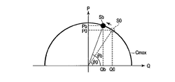
- FIG. 4 is a vector diagram illustrating how to obtain a command value when the command value generation unit according to the first embodiment increases the power factor.
- FIG. 5 is a vector diagram showing the output power of the inverter when there is no inverter in a state where the amount of power generation is reduced under the control of the control device according to the first embodiment.
- FIG. 1 is a configuration diagram showing the configuration of the photovoltaic power generation system according to the first embodiment of the present invention.
- FIG. 2 is a configuration diagram illustrating the configuration of the control device according to the first embodiment.
- FIG. 3 is a vector diagram showing how to obtain command values when the power factor is lowered
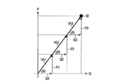
- FIG. 6 is a vector diagram showing the output power of the inverter when there is an inverter with a reduced power generation amount under the control of the control device according to the first embodiment.
- FIG. 7 is a configuration diagram showing the configuration of the control device according to the second embodiment of the present invention.
- FIG. 8 is a vector diagram showing the output power of the inverter when there is an inverter with a reduced power generation amount under the control of the control device according to the second embodiment.
- the solar power generation system 10 converts the DC power generated by the solar cells 2a to 2c into AC power for grid connection with the power system 9, and supplies the power to the power system 9.
- the solar power generation system 10 is a mega solar or the like.
- the solar cells 2a to 2c generate electricity with sunlight.
- the solar cells 2a to 2c may be composed of any number of solar cells.
- the inverters 3a to 3c convert the DC power supplied from the corresponding solar cells 2a to 2c into AC power synchronized with the system voltage of the power system 9.
- Inverters 3a-3c supply AC power to power system 9 via interconnection transformers 4a-4c, respectively.
- the inverters 3a to 3c are power conditioners.
- the AC voltage detector 6 is provided on the output side of the inverters 3a to 3c.
- the AC voltage detector 6 detects the output voltage Vs of the inverters 3a to 3c, and outputs the detected value to the control device 1 as a detection signal.
- an AC voltage detector may be provided on the output side of each of the inverters 3a to 3c.
- the output voltage detected by each AC voltage detector is used for controlling each of the inverters 3a to 3c instead of the output voltage Vs detected by the AC voltage detector 6 of this embodiment.
- the configuration can be the same as that of the form.
- FIG. 2 is a configuration diagram showing the configuration of the control device 1 according to the present embodiment.
- the power generation amount decrease state determination unit 11 determines whether the power generation amount of the solar cells 2a to 2c connected thereto It is determined whether or not the power generation amount of the solar cells 2a to 2c is lower (power generation amount lowering state).
- the power generation amount decrease state determination unit 11 transmits, to the command value generation unit 12, data including information about the output voltage Vs of the inverters 3a to 3c and the output currents I1 to I3 of the inverters 3a to 3c together with the determination result.
- the power generation amount reduction state occurs when the power generation amount of some of the solar cells 2a to 2c decreases compared to normal time (for example, in fine weather) due to the influence of the weather and the like.
- the inverters 3a to 3c having a reduced power generation amount are generated.
- the number of inverters 3a to 3c determined to be in a reduced power generation amount state is one.
- the power generation amount decrease state determination unit 11 determines either the average value of effective components (effective currents) of all output currents I1 to I3 or the average value of effective components of other output currents I2 and I3 excluding its own output current I1. Calculate.
- the power generation amount decrease state determination unit 11 determines that the inverter 3a is in the power generation amount decrease state.
- the reference determined based on the average value may be a value obtained by subtracting a preset value from the average value, or may be a value obtained by multiplying the average value by a ratio of less than 1.
- the command value generator 12 determines the output of the inverters 3a to 3c based on the determination result of the power generation amount decrease state determiner 11, the output currents I1 to I3 of the inverters 3a to 3c, and the output voltage Vs of the inverters 3a to 3c.
- Command values R1, R2, and R3 for controlling the power factor of output power are generated.
- the command values R1 to R3 may include command values for controlling active power or reactive power output from the inverters 3a to 3c, respectively.
- the command value generation unit 12 outputs the generated command values R1 to R3 of the inverters 3a to 3c to the command value output unit 13.
- the command value output unit 13 outputs command values R1 to R3 to the inverters 3a to 3c, respectively. As a result, the output power of each of the inverters 3a to 3c is controlled to follow the command values R1 to R3.
- P1 ⁇ P1max Formula (1) P2 ⁇ P2max Expression (2) P3 ⁇ P3max Formula (3) sqrt (P1 ⁇ 2 + Q1 ⁇ 2) ⁇ VA1max Equation (4) sqrt (P2 ⁇ 2 + Q2 ⁇ 2) ⁇ VA2max Equation (5) sqrt (P3 ⁇ 2 + Q3 ⁇ 2) ⁇ VA3max Equation (6)
- ⁇ is an operator representing a power
- sqrt ()” is a function for calculating a square root in parentheses.
- the power factor of the inverters 3a to 3c is determined as follows.
- an inverter that is not in a power generation reduction state is supplied with surplus generated power as active power increases as the power factor is increased.
- FIG. 3 is a vector diagram showing how to obtain command values R1 to R3 when the command value generator 12 lowers the power factor.
- FIG. 4 is a vector diagram showing how to obtain command values R1 to R3 when the command value generator 12 increases the power factor.
- a semicircular curve Cmax represents a set of operating points of the maximum output power [VA] of the inverters 3a to 3c.
- the output powers VA2 and VA3 of the second inverter 3b and the third inverter 3c that are not in the power generation reduction state are controlled so as to compensate for the change in the output power VA1 of the first inverter 3a.
- the command value generation unit 12 obtains command values R2 and R3 so that the respective power factors of the second inverter 3b and the third inverter 3c are higher than those in the normal time.
- the normal output powers VA2 and VA3 of the second inverter 3b and the third inverter 3c are at the operating point S0 shown in FIG.
- the command value generation unit 12 obtains the power factor of the operating point Sb.
- the power factor at this time corresponds to the angle ⁇ b shown in FIG.
- the command value generation unit 12 generates command values R2 and R3 so as to obtain the calculated power factor. With the command values R2 and R3, the two inverters 3b and 3c shift from the operating point S0 to the operating point Sb.
- the power factor of the two inverters 3b and 3c increases from the angle ⁇ 0 to the angle ⁇ b. Accordingly, the active power output from the two inverters 3b and 3c increases as the reactive power decreases. That is, the active power output from the two inverters 3b and 3c increases from the active power P0 to the active power Pb.
- control device 1 Even when the inverter 3a in the state of reduced power generation is detected, the control device 1 has the total operating point Sf of the output powers VA1 to VA3 of the inverters 3a to 3c changed from the operating point Sf shown in FIG. 5 before detection. Control to not.
- control device 1 increases the reactive power Q1 as much as the active power P1 is reduced by lowering the power factor of the inverter 3a in the power generation reduced state from the angle ⁇ 0 to the angle ⁇ 1.
- control is performed so that the output power VA1 of the inverter 3a in the reduced power generation state is shared and compensated by the output powers VA2 and VA3 of the inverters 3b and 3c that are not in the power generation reduction state. .
- the reactive power Q1 is increased by decreasing the active power P1 by decreasing the power factor of the output power VA1 of the inverter 3a in the power generation reduced state.
- the reactive powers Q2 and Q3 are decreased, and the available active powers P2 and P3 are increased.
- control device 1 has substantially the same active power component, reactive power component, and power factor of the total output power VA1 to VA3 of all the inverters 3a to 3c as before the power generation amount of the solar cell 2a is reduced. Control by value (operating point).
- the power factor of the output power VA1 of the inverter 3a that receives power supply from the solar cells 2a is reduced, and the outputs of the other inverters 3b and 3c
- the power factor of electric power VA2 and VA3 can be raised.
- the change in the output power VA1 of the inverter 3a in the power generation reduced state can be shared and compensated by the output power VA2 and VA3 of the remaining inverters 3b and 3c.
- the operating points (active power, reactive power, and power factor) of the total output power VA1 to VA3 of the inverters 3a to 3c are almost the same as before detection. Can not be.
- FIG. 7 is a configuration diagram showing a configuration of a control device 1A according to the second embodiment of the present invention.
- the control device 1A is obtained by replacing the command value generation unit 12 with a command value generation unit 12A in the control device 1 according to the first embodiment shown in FIG. Other points are the same as those of the control device 1 according to the first embodiment. Here, a different part from control by the control apparatus 1 which concerns on 1st Embodiment is mainly demonstrated.
- FIG. 8 is a vector diagram showing the output powers VA1 to VA3 [VA] of the inverters 3a to 3c when there is an inverter 3a in a state where the power generation amount is reduced under the control of the control device 1A according to the present embodiment.
- the control for lowering the power factor of the first inverter 3a in the power generation reduced state is the same as in the first embodiment.
- the command value generation unit 12A selects one of the inverters 3b and 3c that are not in the power generation amount lowering state.
- the second inverter 3b is selected.
- the output power VA2 of the selected second inverter 3b is controlled so as to compensate for the output power VA1 of the inverter 3a. That is, the sum of the output power VA1 of the first inverter 3a in the reduced power generation amount and the output power VA2 of the second inverter 3b selected for compensation is before the first inverter 3a is in the reduced power generation state.
- the command value R2A of the second inverter 3b is generated so as to be the same.
- the total output power VA1 and VA2 of the first inverter 3a in the power generation reduced state and the second inverter 3b for compensation is the same as before the first inverter 3a is in the power generation reduced state.
- the power factor of the second inverter 3b is obtained. That is, the operating point (active power, reactive power, and power factor) of the two total output powers VA1 and VA2 is increased by increasing the power factor of the second inverter 3b by the amount corresponding to the decrease of the power factor of the first inverter 3a. ) Will not change. About how to raise a power factor, it is the same as that of 1st Embodiment shown in FIG.
- the command value generation unit 12A generates the command value R2A so that the output power VA2 of the second inverter 3b becomes the power factor thus determined.
- the third inverter 3c that has not been selected for compensation is controlled with the same power factor as before the first inverter 3a is in the power generation reduced state. Therefore, the command value R3A for the third inverter 3c generated by the command value generation unit 12A is the same as before the first inverter 3a is in the power generation amount reduction state. If the effective power P2 that can be output from the second inverter 3b is not sufficient to compensate for the decrease in the active power P1 output from the first inverter 3a, the third inverter 3c is also selected for compensation. Is done. In this case, the command value R3A for the third inverter 3c is obtained in the same manner as the command value R2A for the second inverter 3b. The command value R3A increases the power factor of the output power VA3 of the third inverter 3c so as to compensate for the compensation that the output power VA2 of the second inverter 3b is insufficient.
- the power factor of the output power VA1 in the power generation reduced state is lowered, and the power factor of the output power VA2 of the second inverter 3b selected for compensation is raised, thereby making it possible to Similar effects can be obtained.
- the present invention is not limited to the above-described embodiment as it is, and can be embodied by modifying constituent elements without departing from the scope of the invention in the implementation stage.
- various inventions can be formed by appropriately combining a plurality of constituent elements disclosed in the embodiment. For example, some components may be deleted from all the components shown in the embodiment.
- constituent elements over different embodiments may be appropriately combined.
Landscapes
- Engineering & Computer Science (AREA)
- Power Engineering (AREA)
- Inverter Devices (AREA)
- Supply And Distribution Of Alternating Current (AREA)
- Photovoltaic Devices (AREA)
Abstract
太陽光発電システム(10)は、太陽電池(2a~2c)と、太陽電池(2a~2c)にそれぞれ対応して設けられるインバータ(3a~3c)と、インバータ(3a~3c)のそれぞれについて、対応する太陽電池(2a~2c)が予め決められた基準よりも発電量が低下した発電量低下状態か否かを判断し、発電量低下状態と判断された第1のインバータ(3a)の第1の力率を下げる第1の指令値を生成し、第1の指令値に基づいて制御される第1のインバータ(3a)の出力電力を補償するように、発電量低下状態と判断されなかった少なくとも1つの第2のインバータ(3b,3c)の第2の力率を上げる第2の指令値を生成し、第1の指令値及び第2の指令値に基づいて、インバータ(3a~3c)をそれぞれ制御する制御装置(1)とを備える。
Description
本発明は、太陽光発電システムに関する。
一般に、太陽光発電システムは、太陽電池により発電された直流電力を交流電力に変換して、交流負荷に供給することが知られている。直流電力を交流電力に変換するためには、インバータが用いられる。
一方、交流側が並列に接続された複数のインバータで構成される電力変換システムが知られている。例えば、複数のインバータの総和の出力電力として要求される要求電力値を、インバータの台数で割った値よりも小さい設定値と大きい設定値に分けて複数のインバータを制御することが開示されている(特許文献1参照)。また、コントローラと各インバータとの通信周期よりも短い制御周期で、複数のインバータの出力電力を制御することで、複数のインバータの総和の出力電力を制御することが開示されている(特許文献2参照)。
しかしながら、太陽光発電システムでは、複数の太陽電池のそれぞれの発電電力が異なる場合がある。したがって、複数のインバータを常に全て同等に制御すると、一部の太陽電池による発電電力の低下により、太陽光発電システム全体の発電電力が本来発電可能な電力よりも低下する場合がある。
本発明の目的は、一部の太陽電池の発電電力が低下しても、太陽光発電システム全体の発電電力の低下を抑制することのできる太陽光発電システムを提供することにある。
本発明の観点に従った太陽光発電システムは、複数の太陽電池と、前記複数の太陽電池にそれぞれ対応して設けられる複数のインバータと、前記複数のインバータのそれぞれについて、対応する太陽電池が予め決められた基準よりも発電量が低下した発電量低下状態か否かを判断する発電量低下状態判断手段と、前記発電量低下状態判断手段により前記複数のインバータのうち前記発電量低下状態と判断された第1のインバータの第1の力率を下げる第1の指令値を生成する第1の指令値生成手段と、前記第1の指令値生成手段により生成された前記第1の指令値に基づいて制御される前記第1のインバータの出力電力を補償するように、前記発電量低下状態判断手段により前記複数のインバータのうち前記発電量低下状態と判断されなかった少なくとも1つの第2のインバータの第2の力率を上げる第2の指令値を生成する第2の指令値生成手段と、前記第1の指令値生成手段により生成された前記第1の指令値及び前記第2の指令値生成手段により生成された前記第2の指令値に基づいて、前記複数のインバータをそれぞれ制御する制御手段とを備える。
(第1の実施形態)
図1は、本発明の第1の実施形態に係る太陽光発電システム10の構成を示す構成図である。図面における同一部分には同一符号を付してその詳しい説明を省略し、異なる部分について主に述べる。
図1は、本発明の第1の実施形態に係る太陽光発電システム10の構成を示す構成図である。図面における同一部分には同一符号を付してその詳しい説明を省略し、異なる部分について主に述べる。
太陽光発電システム10は、制御装置1、3つの太陽電池2a,2b,2c、3つのインバータ3a,3b,3c、3つの連系トランス4a,4b,4c、3つの交流電流検出器5a,5b,5c、及び、交流電圧検出器6を備える。なお、ここでは、3つのインバータ3a~3cにより構成される太陽光発電システム10について説明するが、2以上であれば、いくつのインバータで構成されてもよい。
太陽光発電システム10は、太陽電池2a~2cにより発電された直流電力を電力系統9と系統連系するための交流電力に変換して、電力系統9に電力供給する。例えば、太陽光発電システム10は、メガソーラなどである。
太陽電池2a~2cは、太陽光により発電する。なお、太陽電池2a~2cは、いくつの太陽電池で構成されてもよい。
インバータ3a~3cは、対応する太陽電池2a~2cから供給される直流電力を電力系統9の系統電圧に同期する交流電力に変換する。インバータ3a~3cは、それぞれ連系トランス4a~4cを介して、電力系統9に交流電力を供給する。例えば、インバータ3a~3cは、パワーコンディショナーである。
連系トランス4a~4cは、各インバータ3a~3cの出力側(交流側)に設けられる。連系トランス4a~4cは、対応するインバータ3a~3cから入力される交流電圧を電力系統9の系統電圧に変圧する。
交流電流検出器5a~5cは、それぞれインバータ3a~3cの出力側に設けられる。交流電流検出器5a~5cは、それぞれインバータ3a~3cの出力電流I1,I2,I3を検出して、検出値を検出信号として制御装置1に出力する。
交流電圧検出器6は、インバータ3a~3cの出力側に設けられる。交流電圧検出器6は、インバータ3a~3cの出力電圧Vsを検出して、検出値を検出信号として制御装置1に出力する。なお、1つの交流電圧検出器6の代わりに、各インバータ3a~3cの出力側に交流電圧検出器を設けてもよい。この場合、各交流電圧検出器で検出された出力電圧を、本実施形態の交流電圧検出器6で検出される出力電圧Vsの代わりに、各インバータ3a~3cの制御に用いることで、本実施形態と同様の構成にすることができる。
制御装置1は、交流電流検出器5a~5cにより検出される各インバータ3a~3cの出力電流I1~I3、及び交流電圧検出器6により検出されるインバータ3a~3cの出力電圧Vsに基づいて、インバータ3a~3cの出力電力を制御する。
図2は、本実施形態に係る制御装置1の構成を示す構成図である。
制御装置1は、発電量低下状態判断部11、指令値生成部12、及び、指令値出力部13を備える。
発電量低下状態判断部11は、インバータ3a~3cの出力電圧Vs及びインバータ3a~3cのそれぞれの出力電流I1~I3に基づいて、自身に接続された太陽電池2a~2cの発電量が他の太陽電池2a~2cの発電量よりも低下している状態(発電量低下状態)であるか否かを判断する。発電量低下状態判断部11は、判断結果と共に、インバータ3a~3cの出力電圧Vs及びインバータ3a~3cのそれぞれの出力電流I1~I3を情報として含むデータを指令値生成部12に送信する。例えば、発電量低下状態は、天候の影響などにより、一部の太陽電池2a~2cの発電量が、通常時(例えば、晴天時)と比較して低下することで生じる。例えば、一部の太陽電池2a~2cに雲がかかった場合に、発電量低下状態のインバータ3a~3cが生じる。以降では、発電量低下状態と判断されるインバータ3a~3cの数が1つの場合について説明するが、一部であれば、いくつのインバータ3a~3cが発電量低下状態と判断されてもよい。
例えば、インバータ3a~3cが発電量低下状態であるか否かの判断は、次のように行う。ここでは、第1のインバータ3aの発電量低下状態の判断方法について説明するが、他のインバータ3b,3cも同じである。発電量低下状態判断部11は、全ての出力電流I1~I3の有効成分(有効電流)の平均値又は自己の出力電流I1を除いた他の出力電流I2,I3の有効成分の平均値のいずれかを演算する。演算した平均値に基づいて決定される基準よりもインバータ3aの出力電流I1の有効成分が低い場合、発電量低下状態判断部11は、インバータ3aが発電量低下状態であると判断する。例えば、平均値に基づいて決定される基準は、平均値から予め設定された値を引いた値でもよいし、平均値に1未満の割合を掛けて求まる値でもよい。
なお、各インバータ3a~3cの出力電流I1~I3の有効成分が低いか否かを判断できれば、発電量低下状態をどのように判断をしてもよい。例えば、上述した平均値の代わりに、どのような統計値を用いてもよい。また、発電に適していない天候(例えば、曇りなど)の時の太陽電池2a~2cの発電量が、発電量低下状態判断部11に予め基準として設定されていてもよい。発電量低下状態判断部11は、この予め設定された基準と各出力電流I1~I3の有効成分を個別に比較することで、各出力電流I1~I3の有効成分が低いか否か判断できる。
指令値生成部12は、発電量低下状態判断部11の判断結果、各インバータ3a~3cの出力電流I1~I3、及び、インバータ3a~3cの出力電圧Vsに基づいて、各インバータ3a~3cの出力電力の力率を制御するための指令値R1,R2,R3を生成する。なお、指令値R1~R3には、それぞれインバータ3a~3cから出力される有効電力又は無効電力を制御するための指令値が含まれていてもよい。指令値生成部12は、生成したインバータ3a~3cの指令値R1~R3を指令値出力部13に出力する。
指令値出力部13は、各インバータ3a~3cにそれぞれ指令値R1~R3を出力する。これにより、各インバータ3a~3cの出力電力は、指令値R1~R3に従うように制御される。
次に、指令値生成部12による指令値R1~R3の求め方について説明する。
初めに、指令値R1~R3の制限について説明する。
各インバータ3a~3cから出力される有効電力[W]をそれぞれP1,P2,P3とし、無効電力[Var]をそれぞれQ1,Q2,Q3とする。各インバータ3a~3cの容量など仕様により定まるそれぞれの最大出力電力[VA]をVA1max,VA2max,VA3maxとする。また、各インバータ3a~3cにそれぞれ電力供給する太陽電池2a~2cの発電電力[W]をP1max,P2max,P3maxとする。この場合において、各インバータ3a~3cから出力される有効電力P1~P3及び無効電力Q1~Q3は、次式を満たさなければならない。
P1≦P1max …式(1)
P2≦P2max …式(2)
P3≦P3max …式(3)
sqrt(P1^2+Q1^2)≦VA1max …式(4)
sqrt(P2^2+Q2^2)≦VA2max …式(5)
sqrt(P3^2+Q3^2)≦VA3max …式(6)
ここで、‘^’は、累乗を表す演算子であり、‘sqrt()’は、括弧内の平方根を演算する関数である。
P2≦P2max …式(2)
P3≦P3max …式(3)
sqrt(P1^2+Q1^2)≦VA1max …式(4)
sqrt(P2^2+Q2^2)≦VA2max …式(5)
sqrt(P3^2+Q3^2)≦VA3max …式(6)
ここで、‘^’は、累乗を表す演算子であり、‘sqrt()’は、括弧内の平方根を演算する関数である。
以降では、断りがない限り、上記の式(1)~(6)を常に全て満たしているものとして説明する。
図5は、第1の実施形態に係る制御装置1による制御下における、発電量低下状態のインバータがない場合のインバータ3a~3cの出力電力VA1,VA2,VA3[VA]を表すベクトル図である。図6は、第1の実施形態に係る制御装置1による制御下における、発電量低下状態のインバータ3aがある場合のインバータ3a~3cの出力電力VA1,VA2,VA3[VA]を表すベクトル図である。図中において、力率は、ベクトルで示した出力電力VA1~VA3の角度で表される。力率が0の場合は、角度は0度であり、力率が1の場合は、角度は90度である。
発電量低下状態判断部11による判断結果により、発電量低下状態のインバータがない場合(通常時)、全てのインバータ3a~3cの出力電力VA1~VA3は、全て同じ力率で制御される。したがって、この場合の出力電力VA1~VA3は、全て同じ角度θ0になる。よって、全てのインバータ3a~3cの出力電力VA1~VA3の合計電力も、角度θ0で表される力率となる。このときの力率は、予め決められた力率であり、電力系統9に供給することが要求されている力率である。
発電量低下状態判断部11による判断結果により、発電量低下状態のインバータがある場合、インバータ3a~3cの力率は、次のように決定される。なお、ここでは、発電量低下状態でないインバータは、力率を上げた分、有効電力が増加するほど余剰に発電電力が供給されているものとして説明する。
まず、発電量低下状態判断部11により、第1のインバータ3aが発電量低下状態と判断された場合について説明する。この場合、指令値生成部12は、第1のインバータ3aの力率が通常時よりも低くなるように指令値R1を求める。
図3は、指令値生成部12により、力率を低くする場合の指令値R1~R3の求め方を示すベクトル図である。図4は、指令値生成部12により、力率を高くする場合の指令値R1~R3の求め方を示すベクトル図である。半円状の曲線Cmaxは、インバータ3a~3cの最大出力電力[VA]の運転点の集合を示している。
第1のインバータ3aの通常時(発電量低下状態でない時)の出力電力は、図3に示す運転点S0にある。太陽電池2aの発電電力は、第1のインバータ3aから出力される有効電力P1と一致する。太陽電池2aの発電電力の低下により、第1のインバータ3aからの出力が有効電力P0から有効電力Paに低下したとする。この場合、指令値生成部12は、曲線Cmax上にあり、有効電力Paとなる運転点Saを求める。指令値生成部12は、第1のインバータ3aの出力電力が運転点Saとなるように力率を求める。このときの力率は、図3に示す角度θaに相当する。指令値生成部12は、求めた力率になるように指令値R1を生成する。この指令値R1により、第1のインバータ3aの出力電力の運転点は、運転点S0から運転点Saに移行する。即ち、第1のインバータ3aの出力電力VA1の力率は、角度θ0から角度θaに下がる。これにより、第1のインバータ3aから出力される無効電力は、有効電力が減少した分増加する。即ち、第1のインバータ3aから出力される無効電力は、無効電力Q0から無効電力Qaに増加する。
発電量低下状態でない第2のインバータ3b及び第3のインバータ3cの出力電力VA2,VA3は、第1のインバータ3aの出力電力VA1の変化を補償するように制御される。このような制御を行うために、指令値生成部12は、第2のインバータ3b及び第3のインバータ3cのそれぞれの力率が通常時よりも高くなるように指令値R2,R3を求める。
第2のインバータ3b及び第3のインバータ3cの通常時の出力電力VA2,VA3は、図4に示す運転点S0にある。2つのインバータ3b,3cの出力電力VA2,VA3を運転点S0から、曲線Cmax上にある運転点Sbに移行する制御を行う場合、指令値生成部12は、運転点Sbの力率を求める。このときの力率は、図4に示す角度θbに相当する。指令値生成部12は、求めた力率になるように指令値R2,R3を生成する。この指令値R2,R3により、2つのインバータ3b,3cは、運転点S0から運転点Sbに移行する。即ち、2つのインバータ3b,3cの力率は、角度θ0から角度θbに上がる。これにより、2つのインバータ3b,3cから出力される有効電力は、無効電力が減少した分増加する。即ち、2つのインバータ3b,3cから出力される有効電力は、有効電力P0から有効電力Pbに増加する。
図6を参照して、発電量低下状態のインバータ3aがある場合の制御装置1によるインバータ3a~3cの制御について説明する。
制御装置1は、発電量低下状態のインバータ3aが検出されても、インバータ3a~3cの出力電力VA1~VA3の合計の運転点Sfが、検出される前の図5に示す運転点Sfと変わらないように制御する。
まず、制御装置1は、発電量低下状態のインバータ3aの力率を角度θ0から角度θ1に下げることで、有効電力P1が低下した分、無効電力Q1を増加させる。
次に、制御装置1は、インバータ3aの出力電力VA1の運転点S1と目標とする全ての出力電力VA1~VA3の合計の運転点Sfとの差から、2つのインバータ3b,3cで分担して補償するための指令値R2,R3を生成する。図6に示すように、2つのインバータ3b,3cの出力電力VA2,VA3の力率をともに角度θ2にすれば、出力電力VA1~VA3の合計が運転点Sfになる。したがって、制御装置1は、力率が角度θ2なるように指令値R2,R3を生成する。
このように生成された指令値R2,R3により、発電量低下状態のインバータ3aの出力電力VA1を発電量低下状態でないインバータ3b,3cの出力電力VA2,VA3で分担して補償するように制御する。
具体的には、発電量低下状態のインバータ3aの出力電力VA1の力率を下げることで、有効電力P1を減少させた分、無効電力Q1を増加させる。一方、発電量低下状態でないインバータ3b,3cの出力電力VA2,VA3の力率を上げることで、無効電力Q2,Q3を減少させた分、余力のある有効電力P2,P3を増加させる。
これにより、制御装置1は、全てのインバータ3a~3cの合計の出力電力VA1~VA3の有効電力成分、無効電力成分、及び力率を、太陽電池2aの発電量が低下する前とほぼ変わらない値(運転点)で制御する。
本実施形態によれば、一部の太陽電池2aの発電量が低下した場合、この太陽電池2aから電源供給を受けるインバータ3aの出力電力VA1の力率を下げ、他のインバータ3b,3cの出力電力VA2,VA3の力率を上げることができる。これにより、発電量低下状態のインバータ3aの出力電力VA1の変化分を残りのインバータ3b,3cの出力電力VA2,VA3で分担して補償することができる。
したがって、一部の太陽電池2aの発電量が低下しても、インバータ3a~3cの合計の出力電力VA1~VA3の運転点(有効電力、無効電力、及び、力率)を検出前とほぼ変わらないようにすることができる。
(第2の実施形態)
図7は、本発明の第2の実施形態に係る制御装置1Aの構成を示す構成図である。
図7は、本発明の第2の実施形態に係る制御装置1Aの構成を示す構成図である。
本実施形態に係る太陽光発電システムは、図1に示す第1の実施形態に係る太陽光発電システム10において、制御装置1を図7に示す制御装置1Aに代えたものである。その他の点は、第1の実施形態に係る太陽光発電システム10と同様である。
制御装置1Aは、図2に示す第1の実施形態に係る制御装置1において、指令値生成部12を指令値生成部12Aに代えたものである。その他の点は、第1の実施形態に係る制御装置1と同様である。ここでは、第1の実施形態に係る制御装置1による制御と異なる部分について主に説明する。
発電量低下状態判断部11による判断結果により、発電量低下状態のインバータ3a~3cが無い場合、図5に示す第1の実施形態と同様に、制御装置1Aは、全てのインバータ3a~3cを同一の力率で制御する。
図8は、本実施形態に係る制御装置1Aによる制御下における、発電量低下状態のインバータ3aがある場合のインバータ3a~3cの出力電力VA1~VA3[VA]を表すベクトル図である。
発電量低下状態の第1のインバータ3aの力率を下げる制御については、第1の実施形態と同様である。
指令値生成部12Aは、発電量低下状態でないインバータ3b,3cのうちいずれか1つを選択する。ここでは、第2のインバータ3bが選択されたものとする。選択された第2のインバータ3bの出力電力VA2は、インバータ3aの出力電力VA1を補償するように制御される。即ち、発電量低下状態の第1のインバータ3aの出力電力VA1と補償用に選択された第2のインバータ3bの出力電力VA2の合計が、第1のインバータ3aが発電量低下状態となる前と同じになるように、第2のインバータ3bの指令値R2Aが生成される。
具体的には、第2のインバータ3bの指令値R2Aは、次のように求める。
発電量低下状態の第1のインバータ3aと補償用の第2のインバータ3bの合計の出力電力VA1,VA2が、第1のインバータ3aが発電量低下状態となる前と同じになるように、第2のインバータ3bの力率を求める。即ち、第1のインバータ3aの力率を下げた分、第2のインバータ3bの力率を上げることで、2つの合計の出力電力VA1,VA2の運転点(有効電力、無効電力、及び力率)が変わらないようにする。力率の上げ方については、図4に示す第1の実施形態と同様である。指令値生成部12Aは、第2のインバータ3bの出力電力VA2がこのように求めた力率になるように指令値R2Aを生成する。
補償用として選択されなかった第3のインバータ3cは、第1のインバータ3aが発電量低下状態になる前と同じ力率で制御される。したがって、指令値生成部12Aが生成する第3のインバータ3cに対する指令値R3Aは、第1のインバータ3aが発電量低下状態になる前と変わらない。もし、第2のインバータ3bから出力可能な有効電力P2だけでは、第1のインバータ3aから出力される有効電力P1の減少分の補償が足りない場合は、第3のインバータ3cも補償用として選択される。この場合、第3のインバータ3cに対する指令値R3Aは、第2のインバータ3bに対する指令値R2Aと同様に求められる。この指令値R3Aにより、第2のインバータ3bの出力電力VA2では足りない補償を補うように第3のインバータ3cの出力電力VA3の力率が上がる。
本実施形態によれば、発電量低下状態の出力電力VA1の力率を下げ、補償用に選択された第2のインバータ3bの出力電力VA2の力率を上げることで、第1の実施形態と同様の作用効果を得ることができる。
また、補償用に選択されなかった第3のインバータ3cの出力電力VA3の力率を変える必要が無く、制御を変えるインバータ3a~3cの数を抑えることができる。
なお、本発明は上記実施形態そのままに限定されるものではなく、実施段階ではその要旨を逸脱しない範囲で構成要素を変形して具体化できる。また、上記実施形態に開示されている複数の構成要素の適宜な組合せにより、種々の発明を形成できる。例えば、実施形態に示される全構成要素から幾つかの構成要素を削除してもよい。さらに、異なる実施形態にわたる構成要素を適宜組み合わせてもよい。
Claims (6)
- 複数の太陽電池と、
前記複数の太陽電池にそれぞれ対応して設けられる複数のインバータと、
前記複数のインバータのそれぞれについて、対応する太陽電池が予め決められた基準よりも発電量が低下した発電量低下状態か否かを判断する発電量低下状態判断手段と、
前記発電量低下状態判断手段により前記複数のインバータのうち前記発電量低下状態と判断された第1のインバータの第1の力率を下げる第1の指令値を生成する第1の指令値生成手段と、
前記第1の指令値生成手段により生成された前記第1の指令値に基づいて制御される前記第1のインバータの出力電力を補償するように、前記発電量低下状態判断手段により前記複数のインバータのうち前記発電量低下状態と判断されなかった少なくとも1つの第2のインバータの第2の力率を上げる第2の指令値を生成する第2の指令値生成手段と、
前記第1の指令値生成手段により生成された前記第1の指令値及び前記第2の指令値生成手段により生成された前記第2の指令値に基づいて、前記複数のインバータをそれぞれ制御する制御手段と
を備えることを特徴とする太陽光発電システム。 - 前記制御手段は、前記発電量低下状態判断手段により前記複数のインバータのいずれも前記発電量低下状態と判断されなかった場合、前記複数のインバータを同一の力率で制御すること
を特徴とする請求項1に記載の太陽光発電システム。 - 前記第2の指令値生成手段は、前記発電量低下状態と判断されなかった全ての前記第2のインバータの前記第2の力率を上げる前記第2の指令値を生成すること
を特徴とする請求項1に記載の太陽光発電システム。 - 前記第2の指令値生成手段は、前記発電量低下状態と判断されなかった前記第2のインバータの前記第2の力率のうち1つの第3の力率を上げ、前記第3の力率を上げても、前記第1のインバータの出力電力の補償が足りない場合、前記第2の力率のうち前記第3の力率以外の第4の力率を上げる前記第2の指令値を生成すること
を特徴とする請求項1に記載の太陽光発電システム。 - 複数の太陽電池にそれぞれ対応して設けられる複数のインバータのそれぞれについて、対応する太陽電池が予め決められた基準よりも発電量が低下した発電量低下状態か否かを判断する発電量低下状態判断手段と、
前記発電量低下状態判断手段により前記複数のインバータのうち前記発電量低下状態と判断された第1のインバータの第1の力率を下げる第1の指令値を生成する第1の指令値生成手段と、
前記第1の指令値生成手段により生成された前記第1の指令値に基づいて制御される前記第1のインバータの出力電力を補償するように、前記発電量低下状態判断手段により前記複数のインバータのうち前記発電量低下状態と判断されなかった少なくとも1つの第2のインバータの第2の力率を上げる第2の指令値を生成する第2の指令値生成手段と、
前記第1の指令値生成手段により生成された前記第1の指令値及び前記第2の指令値生成手段により生成された前記第2の指令値に基づいて、前記複数のインバータをそれぞれ制御する制御手段と
を備えることを特徴とする太陽光発電システムの制御装置。 - 複数の太陽電池にそれぞれ対応して設けられる複数のインバータのそれぞれについて、対応する太陽電池が予め決められた基準よりも発電量が低下した発電量低下状態か否かを判断し、
前記複数のインバータのうち前記発電量低下状態と判断された第1のインバータの第1の力率を下げる第1の指令値を生成し、
前記第1の指令値に基づいて制御される前記第1のインバータの出力電力を補償するように、前記複数のインバータのうち前記発電量低下状態と判断されなかった少なくとも1つの第2のインバータの第2の力率を上げる第2の指令値を生成し、
前記第1の指令値及び前記第2の指令値に基づいて、前記複数のインバータをそれぞれ制御すること
を含むことを特徴とする太陽光発電システムの制御方法。
Priority Applications (2)
| Application Number | Priority Date | Filing Date | Title |
|---|---|---|---|
| JP2018550020A JP6713237B2 (ja) | 2016-11-11 | 2017-04-21 | 太陽光発電システム |
| CN201780052329.4A CN109804557B (zh) | 2016-11-11 | 2017-04-21 | 太阳能发电系统 |
Applications Claiming Priority (2)
| Application Number | Priority Date | Filing Date | Title |
|---|---|---|---|
| US15/349,158 | 2016-11-11 | ||
| US15/349,158 US10536001B2 (en) | 2016-11-11 | 2016-11-11 | Photovoltaic system |
Publications (1)
| Publication Number | Publication Date |
|---|---|
| WO2018087946A1 true WO2018087946A1 (ja) | 2018-05-17 |
Family
ID=62108779
Family Applications (1)
| Application Number | Title | Priority Date | Filing Date |
|---|---|---|---|
| PCT/JP2017/016049 Ceased WO2018087946A1 (ja) | 2016-11-11 | 2017-04-21 | 太陽光発電システム |
Country Status (4)
| Country | Link |
|---|---|
| US (1) | US10536001B2 (ja) |
| JP (1) | JP6713237B2 (ja) |
| CN (1) | CN109804557B (ja) |
| WO (1) | WO2018087946A1 (ja) |
Cited By (1)
| Publication number | Priority date | Publication date | Assignee | Title |
|---|---|---|---|---|
| WO2025017803A1 (ja) * | 2023-07-14 | 2025-01-23 | 株式会社Tmeic | 太陽光発電システム及び制御装置 |
Families Citing this family (3)
| Publication number | Priority date | Publication date | Assignee | Title |
|---|---|---|---|---|
| US10985573B2 (en) * | 2017-09-11 | 2021-04-20 | Toshiba Mitsubishi-Electric Industrial Systems Corporation | Power generation system |
| WO2023157162A1 (ja) * | 2022-02-17 | 2023-08-24 | 東芝三菱電機産業システム株式会社 | 自立系統向け電源システム |
| JP7518401B2 (ja) | 2022-05-16 | 2024-07-18 | ダイキン工業株式会社 | 電力制御システム、負荷装置、制御方法および情報処理装置 |
Citations (4)
| Publication number | Priority date | Publication date | Assignee | Title |
|---|---|---|---|---|
| JP2010074989A (ja) * | 2008-09-19 | 2010-04-02 | Tokyo Gas Co Ltd | 分散型電源システム及びこのシステムを用いた系統電圧安定化方法 |
| WO2015029138A1 (ja) * | 2013-08-27 | 2015-03-05 | 東芝三菱電機産業システム株式会社 | 太陽光発電システム |
| WO2016098200A1 (ja) * | 2014-12-17 | 2016-06-23 | 東芝三菱電機産業システム株式会社 | 太陽光発電所の制御システム |
| JP2016119745A (ja) * | 2014-12-19 | 2016-06-30 | 株式会社デンソー | 電力管理システム |
Family Cites Families (2)
| Publication number | Priority date | Publication date | Assignee | Title |
|---|---|---|---|---|
| CN104221271B (zh) * | 2012-03-30 | 2017-10-24 | 东芝三菱电机产业系统株式会社 | 功率转换装置 |
| ES2637323T3 (es) | 2012-03-30 | 2017-10-11 | Toshiba Mitsubishi-Electric Industrial Systems Corporation | Dispositivo de conversión de potencia |
-
2016
- 2016-11-11 US US15/349,158 patent/US10536001B2/en active Active
-
2017
- 2017-04-21 WO PCT/JP2017/016049 patent/WO2018087946A1/ja not_active Ceased
- 2017-04-21 JP JP2018550020A patent/JP6713237B2/ja active Active
- 2017-04-21 CN CN201780052329.4A patent/CN109804557B/zh active Active
Patent Citations (4)
| Publication number | Priority date | Publication date | Assignee | Title |
|---|---|---|---|---|
| JP2010074989A (ja) * | 2008-09-19 | 2010-04-02 | Tokyo Gas Co Ltd | 分散型電源システム及びこのシステムを用いた系統電圧安定化方法 |
| WO2015029138A1 (ja) * | 2013-08-27 | 2015-03-05 | 東芝三菱電機産業システム株式会社 | 太陽光発電システム |
| WO2016098200A1 (ja) * | 2014-12-17 | 2016-06-23 | 東芝三菱電機産業システム株式会社 | 太陽光発電所の制御システム |
| JP2016119745A (ja) * | 2014-12-19 | 2016-06-30 | 株式会社デンソー | 電力管理システム |
Cited By (2)
| Publication number | Priority date | Publication date | Assignee | Title |
|---|---|---|---|---|
| WO2025017803A1 (ja) * | 2023-07-14 | 2025-01-23 | 株式会社Tmeic | 太陽光発電システム及び制御装置 |
| JPWO2025017803A1 (ja) * | 2023-07-14 | 2025-01-23 |
Also Published As
| Publication number | Publication date |
|---|---|
| JPWO2018087946A1 (ja) | 2019-06-24 |
| US20180138713A1 (en) | 2018-05-17 |
| JP6713237B2 (ja) | 2020-06-24 |
| US10536001B2 (en) | 2020-01-14 |
| CN109804557A (zh) | 2019-05-24 |
| CN109804557B (zh) | 2020-08-07 |
Similar Documents
| Publication | Publication Date | Title |
|---|---|---|
| CN101107442B (zh) | 发电系统 | |
| JP5856028B2 (ja) | パワーコンディショナ及びその制御方法 | |
| JP6713237B2 (ja) | 太陽光発電システム | |
| JP2008278700A (ja) | 分散型発電装置及び電力品質維持制御方法 | |
| WO2013140916A1 (ja) | 系統安定化装置 | |
| KR102264862B1 (ko) | 에너지 저장장치의 관성제어를 위한 장치 및 방법 | |
| Kryonidis et al. | Use of ultracapacitor for provision of inertial response in virtual synchronous generator: Design and experimental validation | |
| KR20220163844A (ko) | 신재생 에너지원의 출력 변동 제어 시스템 및 이의 출력 제어 방법 | |
| JP6607134B2 (ja) | Dc/dcコンバータ及び太陽発電システム | |
| CN103997042B (zh) | 电压调节方法、逆变器及微电网系统 | |
| JP6149275B2 (ja) | 複数蓄電デバイスを用いた電力変動抑制装置 | |
| KR102891480B1 (ko) | 그리드포밍 시스템 및 이의 과도 안정도를 위한 제어 방법 | |
| JP2018152943A (ja) | 制御装置、制御方法およびコンピュータプログラム | |
| JP6768571B2 (ja) | 電力制御装置、方法及び発電システム | |
| JP2014192992A (ja) | 無効電力比率制御器、無効電力比率制御方法、およびこれを用いた発電システム | |
| JP2019041457A (ja) | 電力系統の負荷周波数制御装置及び方法 | |
| JP2018023262A (ja) | 電力供給システム | |
| WO2022163697A1 (ja) | フリッカ抑制装置及びフリッカ抑制制御方法 | |
| JP2013212021A (ja) | 無効電力補償装置 | |
| JP6954357B2 (ja) | 発電システム | |
| JP2008182789A (ja) | 無効電力制御システムおよび無効電力制御方法 | |
| WO2024018558A1 (ja) | 分散電源統合管理装置、電力変換装置、電力系統管理システム、分散電源管理方法およびプログラム | |
| JP2007135256A (ja) | 系統連系インバータ | |
| JP2012155581A (ja) | 電力変換装置 | |
| JP7700499B2 (ja) | 分散電源の制御装置、制御プログラム、及び分散電源システム |
Legal Events
| Date | Code | Title | Description |
|---|---|---|---|
| 121 | Ep: the epo has been informed by wipo that ep was designated in this application |
Ref document number: 17869544 Country of ref document: EP Kind code of ref document: A1 |
|
| ENP | Entry into the national phase |
Ref document number: 2018550020 Country of ref document: JP Kind code of ref document: A |
|
| NENP | Non-entry into the national phase |
Ref country code: DE |
|
| 122 | Ep: pct application non-entry in european phase |
Ref document number: 17869544 Country of ref document: EP Kind code of ref document: A1 |