WO2018083932A1 - 充電率推定装置及び充電率推定方法 - Google Patents
充電率推定装置及び充電率推定方法 Download PDFInfo
- Publication number
- WO2018083932A1 WO2018083932A1 PCT/JP2017/036038 JP2017036038W WO2018083932A1 WO 2018083932 A1 WO2018083932 A1 WO 2018083932A1 JP 2017036038 W JP2017036038 W JP 2017036038W WO 2018083932 A1 WO2018083932 A1 WO 2018083932A1
- Authority
- WO
- WIPO (PCT)
- Prior art keywords
- battery
- charging rate
- rate estimation
- soc
- observer
- Prior art date
- Legal status (The legal status is an assumption and is not a legal conclusion. Google has not performed a legal analysis and makes no representation as to the accuracy of the status listed.)
- Ceased
Links
Images


Classifications
-
- G—PHYSICS
- G01—MEASURING; TESTING
- G01R—MEASURING ELECTRIC VARIABLES; MEASURING MAGNETIC VARIABLES
- G01R31/00—Arrangements for testing electric properties; Arrangements for locating electric faults; Arrangements for electrical testing characterised by what is being tested not provided for elsewhere
- G01R31/36—Arrangements for testing, measuring or monitoring the electrical condition of accumulators or electric batteries, e.g. capacity or state of charge [SoC]
- G01R31/367—Software therefor, e.g. for battery testing using modelling or look-up tables
-
- H—ELECTRICITY
- H01—ELECTRIC ELEMENTS
- H01M—PROCESSES OR MEANS, e.g. BATTERIES, FOR THE DIRECT CONVERSION OF CHEMICAL ENERGY INTO ELECTRICAL ENERGY
- H01M10/00—Secondary cells; Manufacture thereof
- H01M10/42—Methods or arrangements for servicing or maintenance of secondary cells or secondary half-cells
- H01M10/48—Accumulators combined with arrangements for measuring, testing or indicating the condition of cells, e.g. the level or density of the electrolyte
-
- G—PHYSICS
- G01—MEASURING; TESTING
- G01R—MEASURING ELECTRIC VARIABLES; MEASURING MAGNETIC VARIABLES
- G01R31/00—Arrangements for testing electric properties; Arrangements for locating electric faults; Arrangements for electrical testing characterised by what is being tested not provided for elsewhere
- G01R31/36—Arrangements for testing, measuring or monitoring the electrical condition of accumulators or electric batteries, e.g. capacity or state of charge [SoC]
- G01R31/385—Arrangements for measuring battery or accumulator variables
- G01R31/387—Determining ampere-hour charge capacity or SoC
- G01R31/388—Determining ampere-hour charge capacity or SoC involving voltage measurements
-
- H—ELECTRICITY
- H02—GENERATION; CONVERSION OR DISTRIBUTION OF ELECTRIC POWER
- H02J—CIRCUIT ARRANGEMENTS OR SYSTEMS FOR SUPPLYING OR DISTRIBUTING ELECTRIC POWER; SYSTEMS FOR STORING ELECTRIC ENERGY
- H02J7/00—Circuit arrangements for charging or depolarising batteries or for supplying loads from batteries
-
- G—PHYSICS
- G01—MEASURING; TESTING
- G01R—MEASURING ELECTRIC VARIABLES; MEASURING MAGNETIC VARIABLES
- G01R31/00—Arrangements for testing electric properties; Arrangements for locating electric faults; Arrangements for electrical testing characterised by what is being tested not provided for elsewhere
- G01R31/36—Arrangements for testing, measuring or monitoring the electrical condition of accumulators or electric batteries, e.g. capacity or state of charge [SoC]
- G01R31/389—Measuring internal impedance, internal conductance or related variables
-
- Y—GENERAL TAGGING OF NEW TECHNOLOGICAL DEVELOPMENTS; GENERAL TAGGING OF CROSS-SECTIONAL TECHNOLOGIES SPANNING OVER SEVERAL SECTIONS OF THE IPC; TECHNICAL SUBJECTS COVERED BY FORMER USPC CROSS-REFERENCE ART COLLECTIONS [XRACs] AND DIGESTS
- Y02—TECHNOLOGIES OR APPLICATIONS FOR MITIGATION OR ADAPTATION AGAINST CLIMATE CHANGE
- Y02E—REDUCTION OF GREENHOUSE GAS [GHG] EMISSIONS, RELATED TO ENERGY GENERATION, TRANSMISSION OR DISTRIBUTION
- Y02E60/00—Enabling technologies; Technologies with a potential or indirect contribution to GHG emissions mitigation
- Y02E60/10—Energy storage using batteries
Definitions
- the present invention relates to a charging rate estimation device and a charging rate estimation method.
- Patent Document 1 A device that estimates the battery charge rate having a hysteresis in the relationship between the battery charge rate and the open circuit voltage is known (for example, Patent Document 1).
- the battery charge rate can be estimated based on the battery model.
- the parameter representing the battery model is likely to change.
- An error in the parameter due to a change in the parameter representing the battery model can reduce the estimation accuracy of the charging rate of the battery.
- An object of the present invention made in view of such circumstances is to provide a charging rate estimation device and a charging rate estimation method capable of improving the estimation accuracy of the charging rate of a battery.
- the charging rate estimation device estimates the charging rate of the battery using an observer based on a battery model.
- the model includes hysteresis characteristics.
- a charging rate estimation method includes a step of estimating the charging rate of the battery using an observer based on a battery model.
- the model includes hysteresis characteristics.
- the estimation accuracy of the charging rate of the battery can be improved.
- the estimation accuracy of the battery charging rate can be improved.
- FIG. 6 It is a functional block diagram which shows the schematic structural example of a charging rate estimation apparatus. It is a figure which shows an example of a battery equivalent circuit. This is an nth-order Foster-type RC ladder circuit. This is an nth-order Cowell RC ladder circuit. It is a figure which shows an example of a SOC-OCV characteristic. It is a figure which shows an example of the SOC-OCV characteristic which has a hysteresis. It is a figure which shows the example of the battery equivalent circuit containing a hysteresis voltage. It is a figure which shows the example of the battery equivalent circuit which replaced the Warburg impedance of FIG. 6 with the Foster type
- the charging rate estimation device may be mounted on a vehicle such as an electric vehicle or a hybrid electric vehicle.
- the charging rate estimation device may estimate a charging rate of a vehicle battery.
- the vehicle is mounted with an electric motor, a battery, and a controller for driving the vehicle.
- the battery is discharged to supply electric power to the electric motor, regeneratively charged from the electric motor during braking, or charged from the ground charging facility.
- the charging rate estimation device may estimate the charging rate of the battery based on the charge / discharge current flowing through the battery and the terminal voltage of the battery.
- the charging rate estimation device 1 is connected to a battery 4 via a current sensor 2 and a voltage sensor 3.
- the charging rate estimation device 1 may include a current sensor 2 or a voltage sensor 3.
- the charging rate estimation device 1 may be connected to the power supply device 5.
- the charging rate estimation device 1 may input a charging / discharging current from the power supply device 5 to the battery 4.
- the power supply device 5 may be a current source, for example.
- the charging rate estimation device 1 may include a power supply device 5.
- the current sensor 2 detects a charge / discharge current for the battery 4.
- the charge / discharge current is represented by u (t) that is a function of time (t).
- the current sensor 2 outputs the detected charging / discharging current to the charging rate estimation device 1.
- the voltage sensor 3 detects the terminal voltage of the battery 4. In the present embodiment, it is assumed that the terminal voltage is represented by y (t) that is a function of time (t). The voltage sensor 3 outputs the detected terminal voltage to the charging rate estimation device 1.
- the battery 4 may be a secondary battery, for example.
- the secondary battery is also called a rechargeable battery.
- the battery 4 is assumed to be a lithium ion battery in this embodiment.
- the battery 4 may be another type of battery.
- the charging rate estimation device 1 includes a control unit 10 and a storage unit 20.
- the control unit 10 controls each component of the charging rate estimation device 1.
- the control unit 10 may be configured with, for example, a processor or a microcomputer.
- the storage unit 20 may be composed of, for example, a semiconductor memory or a magnetic storage device.
- the control unit 10 may store data or information handled by the charging rate estimation device 1 in the storage unit 20.
- the control unit 10 acquires the charge / discharge current and the terminal voltage of the battery 4 from the current sensor 2 and the voltage sensor 3, respectively.
- the control unit 10 may estimate the internal state of the battery 4 based on the charge / discharge current of the battery 4 and the terminal voltage.
- the internal state of the battery 4 can be represented by a model including the open circuit voltage of the battery 4 and the overvoltage generated inside the battery 4 as parameters.
- the open circuit voltage is also called OCV (Open (Circuit Voltage).
- OCV Open (Circuit Voltage).
- the OCV is a potential difference between the electrodes in the electrochemical equilibrium state of the battery 4.
- the OCV corresponds to the terminal voltage of the battery 4 when no charge / discharge current flows through the battery 4.
- Overvoltage corresponds to the magnitude of the voltage drop caused by the internal impedance.
- the internal impedance is determined according to the reaction rate of the electrochemical reaction inside the battery 4.
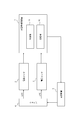
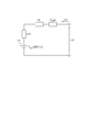
- the model representing the internal state of the battery 4 can be approximated by a battery equivalent circuit as shown in FIG.
- a model approximated by a battery equivalent circuit is also called a battery model.
- the input of the battery equivalent circuit corresponds to the charge / discharge current flowing through the battery 4 and is indicated as u (t).
- u (t) represents the direction of current for charging the battery 4. It is assumed that u (t) is a positive value when a current for charging the battery 4 flows. When the discharge current flows from the battery 4, it is assumed that u (t) has a negative value.
- the output of the battery equivalent circuit corresponds to the terminal voltage of the battery 4 and is shown as y (t). In FIG. 2, it is assumed that the terminal on the tip side of the arrow marked with y (t) corresponds to the positive terminal of the battery 4.
- the OCV of the battery 4 is represented by a voltage source 201 in the battery equivalent circuit.
- the voltage output from the voltage source 201 is represented by OCV (t) that is a function of time.
- the internal impedance of the battery 4 is represented as a circuit in which a resistance indicated by R 0 and a Warburg impedance indicated by Z w (p) are connected in series.
- the resistance indicated by R 0 represents the resistance resulting from the migration process or the like in the electrolyte solution of the battery 4.
- the Warburg impedance represents an impedance resulting from a diffusion process of ions in the battery 4 or the like.
- the overvoltage of the battery 4 is expressed as a voltage drop generated in the internal impedance of the battery 4 due to the current flowing in the battery equivalent circuit.
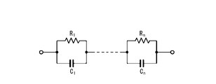
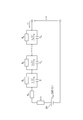
- Warburg impedance for example as shown in Figure 3A, is represented as n-order Foster type circuit parallel circuit is the n connected in series with the capacitor shown as resistor and C 1 ⁇ C n shown as R 1 ⁇ R n It's okay.
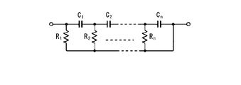
- each of n resistors indicated as R 1 to R n is connected in parallel between n capacitors (C 1 to C n ) connected in series as shown in FIG. 3B. It may also be expressed as an nth order Cowell type circuit.
- the Warburg impedance may be expressed using other linear transfer function models.
- the parameters of the battery equivalent circuit approximating the battery 4 include the resistance value of the resistor constituting the Warburg impedance and the capacitance of the capacitor.
- the parameter of the battery equivalent circuit may be set in advance.
- the parameters of the battery model may be held by the control unit 10 or may be stored in the storage unit 20.
- the control unit 10 estimates the internal state of the battery 4 based on the parameters of the battery equivalent circuit, the charge / discharge current flowing through the battery 4, and the terminal voltage of the battery 4. In the present embodiment, the control unit 10 estimates the charging rate and overvoltage of the battery 4 as the internal state of the battery 4.
- the charge rate of the battery 4 is a ratio of the charge amount to the charge capacity of the battery 4.
- the charging rate is also referred to as SOC (State Of) Charge). It is assumed that the control unit 10 does not estimate the resistance value of the resistor constituting the internal impedance of the battery 4 and the capacitance of the capacitor.
- the controller 10 is not limited to a configuration that does not estimate the resistance value and the capacitance included in the internal impedance.
- the control unit 10 may be configured to estimate a resistance value and a capacity included in the internal impedance.
- the control unit 10 may estimate the OCV and overvoltage of the battery 4. In this case, the control unit 10 can estimate the SOC of the battery 4 based on the OCV of the battery 4.
- the OCV of the battery 4 can be expressed as a function of the SOC.
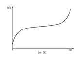
- the relationship between SOC and OCV is referred to as SOC-OCV characteristics.
- the SOC-OCV characteristic can be represented by a graph shown in FIG. 4, for example.
- the horizontal axis and vertical axis in FIG. 4 indicate SOC and OCV, respectively.
- the SOC-OCV characteristic can be obtained in advance by experiments or the like.
- the control unit 10 can estimate the OCV of the battery 4 based on the SOC-OCV characteristic of the battery 4 and the estimated value of the SOC of the battery 4.
- the SOC-OCV characteristic may have a hysteresis characteristic.
- the SOC-OCV characteristics having hysteresis characteristics are different in characteristics during charging and characteristics during discharging.
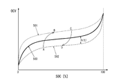
- the SOC-OCV characteristic having the hysteresis characteristic is shown, for example, as shown in FIG.
- the horizontal axis and the vertical axis in FIG. 5 indicate SOC and OCV, respectively.
- the charging SOC-OCV characteristic 501 indicating the SOC-OCV characteristic during charging of the battery 4 is indicated by a broken line.
- a discharge SOC-OCV characteristic 502 indicating an SOC-OCV characteristic at the time of discharging of the battery 4 is indicated by a one-dot chain line.
- the charge SOC-OCV characteristic 501 and the discharge SOC-OCV characteristic 502 form a loop of the SOC-OCV characteristic.
- the loop of the SOC-OCV characteristic formed by the charging SOC-OCV characteristic 501 and the discharging SOC-OCV characteristic 502 is also called a major loop.
- the major loop can be obtained by an experiment of charging / discharging the battery 4.
- the battery 4 is not always charged after being discharged until the SOC becomes 0%.
- the battery 4 can exhibit an SOC-OCV characteristic indicated by a path from the point A to the point B by being charged after being discharged to the point A in FIG.
- the battery 4 is not necessarily discharged after being charged until the SOC reaches 100%.
- the battery 4 can exhibit an SOC-OCV characteristic indicated by a path from the point C to the point D by being discharged after being charged to the point C in FIG.
- a loop having SOC-OCV characteristics smaller than the major loop, which is indicated by a path connected in the order of point A, point B, point C, point D, and point A is also referred to as a minor loop.
- the minor loop can exist virtually infinitely. Minor loops are less likely to be obtained by prior experimentation compared to major loops.
- the SOC-OCV characteristic 500 indicated by a solid line in FIG. 5 corresponds to the average value of the charging SOC-OCV characteristic 501 and the discharging SOC-OCV characteristic 502.
- the SOC-OCV characteristic 500 is not limited to the average value of the charge SOC-OCV characteristic 501 and the discharge SOC-OCV characteristic 502.
- the SOC-OCV characteristic 500 may be a graph included between the charge SOC-OCV characteristic 501 and the discharge SOC-OCV characteristic 502.
- the difference in OCV between the SOC-OCV characteristic 500 and the major loop is also referred to as a hysteresis voltage.
- h (t) The SOC-OCV characteristic having hysteresis can be expressed by the following equation (1) including a hysteresis voltage, instead of being expressed by a minor loop that can exist virtually infinitely.
- f OCV ( ⁇ ) is a function representing the SOC-OCV characteristics 500.
- the SOC-OCV characteristic is expressed as in Expression (1), when the control unit 10 estimates the internal state of the battery 4 together with h (t), the SOC-OCV characteristic is estimated. The accuracy of the conversion can be improved.
- the battery equivalent circuit is expressed as shown in FIG.
- the battery equivalent circuit of FIG. 6 is different from the battery of FIG. 2 in that h (t) representing a hysteresis voltage is added and the output voltage of the voltage source 201 is represented as f OCV (SOC (t)). Different from equivalent circuit.
- the Warburg impedance is represented by a Foster-type circuit shown in FIG. 3A.
- the battery equivalent circuit is expressed as shown in FIG.
- the battery equivalent circuit of FIG. 7 differs from the battery equivalent circuit of FIG. 6 in that Z w (p) is replaced with a Foster-type circuit.
- v k (t) represents the voltage drop that occurs at the capacitance denoted as C k .
- k is an integer of 1 to n.
- the behavior of h (t) is expressed by the following equation (2).
- ⁇ represents the voltage drop speed of the hysteresis model.
- m represents the maximum value of the hysteresis voltage.
- the SOC (t) of the battery 4 at time (t) can be calculated by the following equation (3).
- t 0 represents the measurement start time.
- the integral of the second term on the right side of Equation (3) represents the amount of charge that enters and exits the battery 4 calculated by integrating the charge / discharge current.
- the overvoltage is expressed as the following expression (4) based on the internal impedance of the battery 4 and the charge / discharge current of the battery 4.
- ⁇ (t) represents an overvoltage.
- G ⁇ (p) represents the internal impedance and is the sum of R 0 and Z w (p).
- Z w (p) is expressed by the following equation (5).
- R d represents a diffusion resistance
- C d represents the diffusion capacity.
- the battery model represented by the battery equivalent circuit of FIG. 7 is represented by an input / output system that takes charge / discharge current as an input and terminal voltage as an output.
- An input / output system is also simply called a system.
- the input / output system can be represented as a state space represented by the following equations (8) and (9).
- Equation (8) is a state equation representing the relationship between the input and the state variable.
- Expression (9) is an output equation representing the relationship between the state variable and the output.
- a (u (t)) in the equation (8) is a (n + 2) ⁇ (n + 2) -order matrix in the real space, and is represented by the following equation (10).
- diag is a function that outputs a diagonal matrix.
- a (u (t)) is also called a system matrix.
- the system matrix represents at least some of the characteristics of the system.
- the system matrix of equation (8) depends on u (t), which represents the input to the system. Therefore, it can be said that the system represented by the equations (8) and (9) is a parameter variable system.
- the parameter variable system is also called a PV (Parameter Varying) system.
- the model of the battery 4 represented by the battery model of FIG. 7 can be represented by a PV system.
- X (t) in the equations (8) and (9) is a state variable, and is represented by the following equation (13).
- the charging rate estimation apparatus 1 can estimate the internal state of the battery 4 by estimating the state variable in the PV system representing the model of the battery 4.
- the control unit 10 inputs the charge / discharge current acquired from the current sensor 2 to the model of the battery 4 and calculates an estimated value of the terminal voltage.
- the control unit 10 feeds back the difference between the estimated value of the terminal voltage and the actual terminal voltage to the model of the battery 4 and sequentially estimates the SOC of the battery 4.
- the PV system representing the model of the battery 4 is a linear parameter variable system.
- the linear parameter variable system is also called an LPV (LinearLineParameter Varying) system.
- LPV LinearLineParameter Varying
- the LPV system can be expressed as a state space represented by the following equations (14) to (18). As shown in the equations (16) to (18), A as the system matrix can be expressed in a polytope form.
- the polytope format is a format in which a function is expressed by a linear combination. The primary combination is also called a linear combination.
- Expression (14) is a state equation representing a relationship between an input to the system and a state variable representing an internal state of the system.
- Equation (15) is an output equation representing the relationship between the state variable and the output from the system.
- x (t) is an nth-order column vector in real space and represents a state variable.
- u (t) is a nu- order column vector in real space and represents an input to the system.
- y (t) is an n y -th order column vector in real space and represents the output from the system.
- n, n u and n y are set according to the state, the size of the input and output signals, respectively.
- the size of the matrix represented as A ( ⁇ (t)), B, and C is set according to the size of each signal.
- U (t) which is an input to the system represented by equations (14) and (15), is a vector and is written in bold.
- U (t) which is an input to the system represented by the equations (8) and (9), is a scalar and is written in fine characters.
- u (t) representing a vector is represented as u ⁇ (t) below.
- x (t) and y (t) representing vectors are represented as x ⁇ (t) and y ⁇ (t), respectively.
- represents the norm.
- the norm of the signal represents the magnitude of the signal.
- represents the magnitude of x (t).
- 2 represents the L 2 norm.
- the L 2 norm is calculated as the square root of the value obtained by squaring the components included in the signal.
- L 2 norm is a kind of norm. Symbols, denoted L 2 in formula (21) shows the L 2 space. In Expression (21), u ⁇ is an element of the L 2 space.
- the charging rate estimation apparatus 1 estimates system state variables and output from the system.
- An error may occur between the estimated value and the true value.
- An error that occurs between the estimated value and the true value is also referred to as an estimation error. Disturbances can be added to the input of the system. State variables and output estimation errors can be large due to disturbances applied to the input.
- x ⁇ (t), u ⁇ (t), and y ⁇ (t) represent the state variables of the system, the input to the system, and the output from the system, respectively, as in equations (14) and (15).
- z (t) is an n z -th order column vector in real space and represents the evaluation output of the system.
- the evaluation output of the system includes an output to be evaluated with particular attention among the outputs from the system.
- the evaluation may be performed with respect to disturbance suppression performance or quick response.
- z (t) representing a vector is represented as z ⁇ (t).
- w (t) is an n w -th order column vector in real space and represents a disturbance applied to the input to the system.
- w (t) representing a vector is represented as w ⁇ (t).
- n z and n w are set according to the size of the evaluation output and the signal of the disturbance, respectively.
- a ( ⁇ (t)) is given by equations (16) to (18).
- the size of the coefficient matrix represented as B 1 , B 2 , C 1 , C 2 and D is set according to the size of the state variable, input, output, evaluation output, and disturbance signal.
- Equation (22) is a state equation representing the relationship between the input to the system to which a disturbance has been applied and a state variable representing the internal state of the system.
- Expression (23) is an output equation representing the relationship between the state variable and the input to the system and the output from the system.
- Expression (24) is an evaluation output equation representing the relationship between the state variable and the evaluation output of the system.
- Expressions (25) to (27) are derived by replacing state variables, outputs, and evaluation outputs with estimated values, respectively.
- the estimated values of the state variable, the output, and the evaluation output are represented by adding a symbol ⁇ on x, y, and z, respectively.
- the terms with the symbol ⁇ on x ⁇ (t), y ⁇ (t) and z ⁇ (t) are x ⁇ ⁇ (t), y ⁇ ⁇ (t) and z ⁇ ⁇ (t). Also expressed.
- the estimation error of the state variable is expressed by the following equation (28).
- the estimation error of the state variable is represented by adding a symbol ⁇ on x ⁇ (t).
- the term with the symbol ⁇ on x ⁇ (t) is also expressed as x ⁇ ⁇ (t).
- equation (29) when A ( ⁇ (t)) is stable, the estimation error of the state variable can converge with the passage of time. In other words, whether or not the estimation error converges can be determined depending on whether or not the system matrix is stable.
- L can be set so that A ( ⁇ (t))-LC is stable. In other words, L can be set such that the estimation error converges regardless of whether the system matrix is stable or not.
- Formulas composed of Formulas (30), (26), and (27) are also referred to as observers to the system.
- the observer is also called a state estimator.
- An observer refers to a mechanism that estimates state variables that cannot be directly observed based on inputs and outputs when at least some of the state variables cannot be directly observed.
- An observer for a system representing a model is also called a model-based observer.
- L in Expression (30) is also referred to as an observer gain. Setting or determining L is also referred to as observer gain design.
- the estimation errors of the state variables, the output, and the evaluation output are represented by the following equations (33) to (35), respectively. It is represented by The estimation errors of the output and the evaluation output are represented by adding a symbol ⁇ on y and z, respectively. In the following, the terms with the symbol ⁇ on y and z are also expressed as y ⁇ and z ⁇ .
- the relationship between the estimation errors of the state variables, output, and evaluation output shown in equations (33) to (35) is also called a deviation system.
- the observer gain can be designed to have an attenuation performance that indicates the rate of attenuation of the estimation error of the state variable that exists in the initial state of the system, or a performance that reduces the influence of the disturbance on the estimation error of the evaluation output.
- the observer gain can be designed in various ways. For example, it is assumed that positive definite matrix X and matrix Y exist for positive numbers a and ⁇ , and LMI expressed by the following equation (36) is established.
- the initial state of the system is the state of the system when time (t) is 0.
- x ⁇ ⁇ (0) represents an estimation error of a state variable existing in the initial state of the system.
- the estimation error of the state variable existing in the initial state of the system is also called the initial value error of the state estimation value.
- a represents the speed at which the initial value error of the state estimation value attenuates, and is also referred to as the degree of attenuation.
- b is a coefficient that can be appropriately determined. Equation (38) shows that the magnitude of the state variable estimation error can be attenuated below a predetermined speed.
- Equation (36) When the LMI expressed by Equation (36) is satisfied and the observer gain is designed based on Equation (37), the input / output response to the deviation system expressed by Equations (33) to (35) is Formula (39) is satisfy
- ⁇ is a coefficient that can be determined as appropriate, and indicates the degree of influence of the evaluation output from disturbance. Equation (39) shows that the evaluation output can be reduced to less than a predetermined ratio to the disturbance.
- equation (36) When equation (36) is established and the observer gain is designed based on equation (37), the fact that equations (38) and (39) are satisfied is given as a theorem derived based on the first theorem. It is done.
- the theorems shown in equations (36) to (39) are also called second theorems.
- the charging rate estimation apparatus 1 can attenuate an estimation error of a state variable of the system at a predetermined speed or more by appropriately designing an observer for the system.
- the charging rate estimation apparatus 1 according to the present embodiment can reduce the influence of disturbance on the estimation output estimation error by appropriately designing an observer for the system.
- a system corresponding to the model of the battery 4 can be expressed by equations (8) to (13).
- the model of the battery 4 includes a hysteresis model, disturbances due to the uncertainty of the parameters of the hysteresis model can be added to the input to the system.
- m and ⁇ included in the equation (2) as parameters of the hysteresis model may have a modeling error with respect to the true value.
- the nominal values of m and ⁇ are parameters of the hysteresis model.
- the nominal values of m and ⁇ are values assumed as m and ⁇ , respectively.
- Expression (41) is the same expression as Expression (9).
- W (t) in the equation (40) represents a disturbance caused by the uncertainty of the parameters of the hysteresis model.
- w (t) is represented by the following formula (42).
- sgn (•) represents a sign function.
- the sign function is a function that outputs 1 when the input value is a positive value, outputs -1 when the input value is a negative value, and outputs 0 when the input value is 0. .
- ⁇ m represents the difference between the true value of m and the nominal value.
- ⁇ represents a difference between a true value of ⁇ and a nominal value.
- U (t), y (t), and w (t) included in the equations (40) and (41) represent scalars, respectively, and u ⁇ (t), y ⁇ (t), and w ⁇ (t). Differentiated.
- F of Formula (40) is represented by the following Formula (43).
- f is expressed by Expression (43), according to Expressions (13) and (40), the component of w (t) representing the disturbance is h (t) among the components included in x (t). Only join.
- Equations (40) and (41) represent the system of the battery 4 in consideration of the hysteresis model parameter error.
- the observer represented by the following equations (44) and (45) may be configured.
- x ⁇ ⁇ (t) and y ⁇ (t) represent estimated values of x ⁇ (t) and y (t), respectively.
- the estimated value of the SOC is represented by adding a symbol ⁇ on the SOC.
- the term with the symbol ⁇ on the SOC is also expressed as SOC ⁇ .
- L is a (n + 2) -th column vector in real space and represents an observer gain.
- f OCV ( ⁇ ) is linearized, and the following equation (46) is derived.
- ⁇ is a constant that can be appropriately determined.
- Equation (50) is introduced as an evaluation output equation for determining the evaluation output of the system.
- c z is represented by the following formula (51).
- c z when reflecting the estimation error of the state variable to the evaluation output, giving a weighting to components included in the estimated error of the state variable.
- Equations (48) and (50) represent a system in which the input is w (t) and the output is z (t).
- the system represented by the formulas (48) and (50) is represented as G (L).
- G (L) is an LPV system whose system matrix depends on u (t).
- G (L) is BIBO (BoundedBoundInput Bounded Output) stable and the input / output gain of G (L) is sufficiently small, the estimation error of SOC can be reduced regardless of the input of w (t). .
- BIBO stability means that if the input to the system is a finite value, the output from the system is a finite value.
- Equation (53) is an equation showing the attenuation constraint that the free response of G (L) should satisfy with respect to the estimation error of the state variable in the initial state of the system.
- a is a positive number indicating the degree of attenuation of the free response of G (L).
- b is a coefficient that can be appropriately determined.
- Expression (53) is an expression corresponding to Expression (38).
- Expression (54) is an expression showing the L 2 gain constraint that the L 2 gain of G (L) should satisfy.
- L 2 gain G (L) is defined as the upper bound of the ratio of the L 2 norm of the input signal G evaluation output signal of the (L) of L 2 norm and G (L).
- ⁇ is a positive number that specifies the upper bound range of the L 2 gain of G (L).
- the L 2 gain of G (L) means the ratio of the magnitude of the evaluation output to the error of the parameter included in the model represented by the system.
- the observer gain can be designed so that the two constraints expressed by the equations (53) and (54) are satisfied simultaneously.
- the observer gain can be set to satisfy a predetermined constraint condition.
- the predetermined constraints include an attenuation constraint and an L 2 gain constraint.
- a in Expression (53) may be set such that the SOC estimation error of the battery 4 converges within a predetermined time.
- ⁇ may be minimized so that the equation (54) is further satisfied.
- the magnitude of the charge / discharge current of the battery 4 is represented as
- the system matrix of the system representing the model of the battery 4 can be expressed in a polytope form represented by the following equations (55) to (58).
- u min is the minimum value of
- u max is the maximum value of
- ⁇ 1 (u (t)) and ⁇ 2 (u (t)) are polytope type parameters.
- the system matrix constitutes at least a part of the observer parameters represented by the equations (44) and (45).
- the system matrix is expressed in the polytope format.
- a (u (t)) is expressed in a polytope form, and positive definite matrix X and matrix Y exist for positive numbers a and ⁇ , and are expressed by the following equations (59) and (60). Assume that LMI is established. In the equations (59) and (60), the following equation (61) is established.
- an observer gain such that G (L) simultaneously satisfies the expressions (53) and (54) is designed by the following expression (62).
- the positive definite matrix X and the matrix Y can be calculated so that the LMI expressed by the equations (59) and (60) is satisfied and ⁇ is minimized. Based on the positive definite matrix X and the matrix Y calculated in this way, an observer gain having a smaller L 2 gain can be designed.
- the L 2 gain of G (L) is the ratio of the magnitude of the estimation error of the charging rate of the battery 4 to the error of the parameter included in the battery model.
- the charging rate estimation device 1 estimates the SOC of the battery 4 using an observer based on the model of the battery 4 including hysteresis characteristics. By using the observer, the estimation accuracy of the SOC of the battery 4 can be improved even when there is an error in the parameter of the model of the battery 4 due to the influence of the hysteresis characteristic or the like. Moreover, the calculation load of the charging rate estimation apparatus 1 can be reduced as compared with the case where the parameter error is reduced by the sequential estimation of the parameters of the battery model.
- the observer gain is set so as to reduce the estimation error of the SOC according to the error of the parameter included in the model of the battery 4, so that the estimation accuracy of the SOC of the battery 4 can be improved.
- the estimation accuracy of the SOC of the battery 4 can be improved by setting the observer gain so as to satisfy a predetermined constraint condition.
- the observer gain can be easily calculated. Also, the observer gain can be easily calculated by satisfying the predetermined LMI for the observer gain.
- the predetermined LMI that the observer gain satisfies includes the attenuation degree a as a parameter, the influence of the parameter error on the estimated SOC value can be further reduced.
- the charging rate estimation apparatus 1 may estimate the SOC of the battery 4 by the charging rate estimation method shown in FIG.
- the control unit 10 acquires the parameters of the battery model of the battery 4 (step S1).
- the control unit 10 may acquire the parameters of the battery model from the storage unit 20 or an external device.
- the control unit 10 acquires an observer for the system represented by the battery model of the battery 4 (step S2).
- the control unit 10 may design an observer based on the parameters of the battery model, the equation (62), and the like.
- the control unit 10 may acquire a previously designed observer from the storage unit 20 or an external device.
- Control unit 10 estimates the SOC of battery 4 (step S3).
- the control unit 10 can estimate the SOC of the battery 4 based on the acquired observer. By doing in this way, the estimation precision of SOC of the battery 4 can be improved.
- the SOC of the battery 4 can be estimated by an observer including an observer gain designed based on the equation (62) and the like.
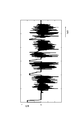
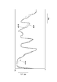
- FIG. 9, FIG. 10, and FIG. 11 will be referred to in an example of the SOC estimation result.
- FIG. 9 shows, as an example of time variation of current, time variation of current when the battery 4 is mounted on an electric vehicle and a running experiment is performed.
- the observer used for the SOC estimation in this example was designed so that G (L) satisfies the expressions (53) and (54) at the same time.
- the observer used for the SOC estimation of the present embodiment was designed in consideration of both the attenuation degree constraint and the L 2 gain constraint.
- SOC estimation according to the comparative example SOC estimation using an observer designed so that G (L) satisfies Expression (53) was performed.
- Observer used in SOC estimation according to the comparative example without considering the L 2 gain-constrained, which is designed in consideration of only the attenuation restrictions.
- the SOC of the battery 4 was estimated using the observer designed in each of the example and the comparative example.
- the horizontal axis and the vertical axis indicate time and SOC, respectively.
- the true value of the SOC is indicated by a broken line.
- the true value of the SOC is a value calculated by a method such as integrating the input current to the battery 4.
- the estimated SOC value according to the embodiment is indicated by a solid line.
- the estimated value of the SOC according to the comparative example is indicated by a one-dot chain line.
- the estimated value of the SOC according to the example is close to the true value of the SOC as compared with the estimated value of the SOC according to the comparative example.
- the estimation error of the SOC using the observer of the example is smaller than the estimation error of the SOC using the observer of the comparative example.
- the SOC estimation error is the difference between the estimated SOC value and the true SOC value.
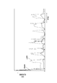
- the horizontal axis and the vertical axis indicate time and SOC estimation errors, respectively.
- the RMSE of the SOC estimation error using the observer according to the comparative example was 4.5%.
- the RMSE of the SOC estimation error using the observer according to the example was 1.9%.
- the observer is designed in consideration of predetermined constraint conditions including the attenuation constraint and the L 2 gain constraint, so that the estimation accuracy of the SOC is improved. It can be improved.
- SYMBOLS 1 Charge rate estimation apparatus 2 Current sensor 3 Voltage sensor 4 Battery 5 Power supply device 10 Control part 20 Memory
Landscapes
- Engineering & Computer Science (AREA)
- Manufacturing & Machinery (AREA)
- Chemical & Material Sciences (AREA)
- Chemical Kinetics & Catalysis (AREA)
- Electrochemistry (AREA)
- General Chemical & Material Sciences (AREA)
- Physics & Mathematics (AREA)
- General Physics & Mathematics (AREA)
- Power Engineering (AREA)
- Secondary Cells (AREA)
- Charge And Discharge Circuits For Batteries Or The Like (AREA)
- Tests Of Electric Status Of Batteries (AREA)
Priority Applications (2)
| Application Number | Priority Date | Filing Date | Title |
|---|---|---|---|
| DE112017005514.8T DE112017005514T5 (de) | 2016-11-02 | 2017-10-03 | Laderatenabschätzeinrichtung und laderatenabschätzverfahren |
| CN201780063665.9A CN109844551B (zh) | 2016-11-02 | 2017-10-03 | 观测器增益的设定方法 |
Applications Claiming Priority (2)
| Application Number | Priority Date | Filing Date | Title |
|---|---|---|---|
| JP2016-215476 | 2016-11-02 | ||
| JP2016215476A JP6869697B2 (ja) | 2016-11-02 | 2016-11-02 | オブザーバゲインの設定方法 |
Publications (1)
| Publication Number | Publication Date |
|---|---|
| WO2018083932A1 true WO2018083932A1 (ja) | 2018-05-11 |
Family
ID=62076784
Family Applications (1)
| Application Number | Title | Priority Date | Filing Date |
|---|---|---|---|
| PCT/JP2017/036038 Ceased WO2018083932A1 (ja) | 2016-11-02 | 2017-10-03 | 充電率推定装置及び充電率推定方法 |
Country Status (4)
| Country | Link |
|---|---|
| JP (1) | JP6869697B2 (enExample) |
| CN (1) | CN109844551B (enExample) |
| DE (1) | DE112017005514T5 (enExample) |
| WO (1) | WO2018083932A1 (enExample) |
Cited By (1)
| Publication number | Priority date | Publication date | Assignee | Title |
|---|---|---|---|---|
| CN113728242A (zh) * | 2019-05-08 | 2021-11-30 | 特艾斯技术有限责任公司 | 对可充电电池中的析锂进行表征 |
Families Citing this family (6)
| Publication number | Priority date | Publication date | Assignee | Title |
|---|---|---|---|---|
| JP7141620B2 (ja) * | 2017-03-03 | 2022-09-26 | マレリ株式会社 | オブザーバゲインの設定方法 |
| JP7203375B2 (ja) * | 2018-11-20 | 2023-01-13 | マレリ株式会社 | 充電率推定装置及び充電率推定方法 |
| KR102599803B1 (ko) * | 2020-12-10 | 2023-11-09 | 한국에너지기술연구원 | Soc추정을 통해 배터리 상태를 진단하는 방법 및 장치 |
| DE102021005322A1 (de) | 2021-10-26 | 2021-12-16 | Daimler Ag | Verfahren zum Bestimmen eines aktuellen Ladezustands eines elektrischen Energiespeichers, sowie Implementierung im Energiemanagementsystem |
| KR102885443B1 (ko) * | 2022-12-29 | 2025-11-13 | 한국에너지기술연구원 | 전기자동차 충전스테이션의 전압안정화 장치 및 방법 |
| US20250110178A1 (en) * | 2023-10-03 | 2025-04-03 | GM Global Technology Operations LLC | State-of-charge estimator for lithium-ion battery using hysteresis model |
Citations (1)
| Publication number | Priority date | Publication date | Assignee | Title |
|---|---|---|---|---|
| JP2011033453A (ja) * | 2009-07-31 | 2011-02-17 | Honda Motor Co Ltd | 蓄電装置の内部抵抗検出装置および開路電圧検出装置および残容量検出装置 |
Family Cites Families (5)
| Publication number | Priority date | Publication date | Assignee | Title |
|---|---|---|---|---|
| CN104007395B (zh) * | 2014-06-11 | 2016-08-24 | 北京交通大学 | 锂离子电池荷电状态与参数自适应联合估计方法 |
| US10408880B2 (en) * | 2014-08-19 | 2019-09-10 | Fca Us Llc | Techniques for robust battery state estimation |
| JP6450565B2 (ja) | 2014-10-31 | 2019-01-09 | カルソニックカンセイ株式会社 | バッテリのパラメータ推定装置 |
| JP6498034B2 (ja) | 2015-05-19 | 2019-04-10 | キヤノン株式会社 | インクジェット記録装置、制御方法およびプログラム |
| CN105353313B (zh) * | 2015-09-28 | 2020-07-28 | 欣旺达电子股份有限公司 | 电池荷电状态的估算方法和装置 |
-
2016
- 2016-11-02 JP JP2016215476A patent/JP6869697B2/ja not_active Expired - Fee Related
-
2017
- 2017-10-03 WO PCT/JP2017/036038 patent/WO2018083932A1/ja not_active Ceased
- 2017-10-03 CN CN201780063665.9A patent/CN109844551B/zh not_active Expired - Fee Related
- 2017-10-03 DE DE112017005514.8T patent/DE112017005514T5/de not_active Withdrawn
Patent Citations (1)
| Publication number | Priority date | Publication date | Assignee | Title |
|---|---|---|---|---|
| JP2011033453A (ja) * | 2009-07-31 | 2011-02-17 | Honda Motor Co Ltd | 蓄電装置の内部抵抗検出装置および開路電圧検出装置および残容量検出装置 |
Non-Patent Citations (3)
| Title |
|---|
| FENG, X. Y. ET AL.: "A battery model including hysteresis for State-of-Charge estimation in Ni-MH battery", VEHICLE POWER AND PROPULSION CONFERENCE, 18 November 2008 (2008-11-18), XP031363129, Retrieved from the Internet <URL:http://ieeexplore.ieee.org/document/4677449> [retrieved on 20171220] * |
| HATTAHA, KENICHI ET AL.: "Robust observer design for state-of-charge estimation of rechargeable battery", PROCEEDINGS OF THE JAPAN JOINT AUTOMATIC CONTROL CONFERENCE, 20 December 2017 (2017-12-20), pages 554 - 559, Retrieved from the Internet <URL:http://www.jstage.jst.go.jp/article/jacc/59/0/59-554/_article/-char/ja> * |
| WANG, D. ET AL.: "Dynamic function and control for polytopic system (1st Report, Polytopic observer design by LMI formulation", TRANSACTIONS OF THE JAPAN SOCIETY OF MECHANICAL ENGINEERS (SERIES C, vol. 67, no. 663, 26 February 2008 (2008-02-26), pages 3484 - 3490, XP055501761, Retrieved from the Internet <URL:URL:https://www.jstage.jst.go.jp/article/kikaicl979/67/663/67_663_6484/_article/-har/ja/><DOI:https://doi.org/10.1299/kikaic.67.3484> [retrieved on 20171220] * |
Cited By (2)
| Publication number | Priority date | Publication date | Assignee | Title |
|---|---|---|---|---|
| CN113728242A (zh) * | 2019-05-08 | 2021-11-30 | 特艾斯技术有限责任公司 | 对可充电电池中的析锂进行表征 |
| US12265131B2 (en) | 2019-05-08 | 2025-04-01 | TWAICE Technologies GmbH | Characterisation of lithium plating in rechargeable batteries |
Also Published As
| Publication number | Publication date |
|---|---|
| CN109844551B (zh) | 2021-04-13 |
| JP6869697B2 (ja) | 2021-05-12 |
| CN109844551A (zh) | 2019-06-04 |
| JP2018072265A (ja) | 2018-05-10 |
| DE112017005514T5 (de) | 2019-12-05 |
Similar Documents
| Publication | Publication Date | Title |
|---|---|---|
| JP6869697B2 (ja) | オブザーバゲインの設定方法 | |
| Song et al. | Current profile optimization for combined state of charge and state of health estimation of lithium ion battery based on Cramer–Rao bound analysis | |
| JP6848144B2 (ja) | 二次電池の充電状態を推定するための装置及びその方法 | |
| CN113728242B (zh) | 对可充电电池中的析锂进行表征 | |
| Taborelli et al. | State of charge estimation using extended Kalman filters for battery management system | |
| EP2852848B1 (en) | Battery system and method with parameter estimator | |
| US12252021B2 (en) | Method for estimating an operating parameter of a battery unit | |
| CN110290972B (zh) | 估计电池单体的充电状态的方法 | |
| US20240337699A1 (en) | Battery control device | |
| CN114845901A (zh) | 用于确定电能存储系统功率状态值的方法 | |
| US20200072146A1 (en) | Control device and control method | |
| JP6171897B2 (ja) | 近似関数作成プログラム、近似関数作成方法、近似関数作成装置および充電率推定プログラム | |
| CN110462412A (zh) | 用于估计电池的soc的装置和方法 | |
| Xie et al. | Available power prediction limited by multiple constraints for LiFePO4 batteries based on central difference Kalman filter | |
| JP2017223536A (ja) | 電池状態推定装置および電池状態推定方法 | |
| JP2018009939A (ja) | シミュレーション方法及びシミュレーション装置 | |
| JP2021532370A (ja) | 充電状態推定装置及び方法 | |
| CN110726937B (zh) | 用于确定状态噪声协方差矩阵的方法和相应设备 | |
| EP4083639B1 (en) | Method and apparatus for estimating power limit value of battery pack, and battery management system | |
| JP7141620B2 (ja) | オブザーバゲインの設定方法 | |
| WO2018011993A1 (ja) | シミュレーション方法及びシミュレーション装置 | |
| CN107831445A (zh) | 一种获取电池剩余电量的方法和装置 | |
| US12000901B2 (en) | Battery state estimation based on multiple rates of hysteresis transit | |
| Sakile et al. | Estimation of lithium‐ion battery state of charge for electric vehicles using a nonlinear state observer | |
| CN112689770A (zh) | 用于估计电池的健康状态的方法和系统 |
Legal Events
| Date | Code | Title | Description |
|---|---|---|---|
| 121 | Ep: the epo has been informed by wipo that ep was designated in this application |
Ref document number: 17867931 Country of ref document: EP Kind code of ref document: A1 |
|
| 122 | Ep: pct application non-entry in european phase |
Ref document number: 17867931 Country of ref document: EP Kind code of ref document: A1 |