WO2018079697A1 - 車載更新システム及び車載更新装置 - Google Patents
車載更新システム及び車載更新装置 Download PDFInfo
- Publication number
- WO2018079697A1 WO2018079697A1 PCT/JP2017/038836 JP2017038836W WO2018079697A1 WO 2018079697 A1 WO2018079697 A1 WO 2018079697A1 JP 2017038836 W JP2017038836 W JP 2017038836W WO 2018079697 A1 WO2018079697 A1 WO 2018079697A1
- Authority
- WO
- WIPO (PCT)
- Prior art keywords
- vehicle
- update
- relay
- battery
- power supply
- Prior art date
- Legal status (The legal status is an assumption and is not a legal conclusion. Google has not performed a legal analysis and makes no representation as to the accuracy of the status listed.)
- Ceased
Links
Images


Classifications
-
- G—PHYSICS
- G06—COMPUTING OR CALCULATING; COUNTING
- G06F—ELECTRIC DIGITAL DATA PROCESSING
- G06F8/00—Arrangements for software engineering
- G06F8/60—Software deployment
- G06F8/65—Updates
-
- G—PHYSICS
- G06—COMPUTING OR CALCULATING; COUNTING
- G06F—ELECTRIC DIGITAL DATA PROCESSING
- G06F8/00—Arrangements for software engineering
- G06F8/60—Software deployment
- G06F8/65—Updates
- G06F8/654—Updates using techniques specially adapted for alterable solid state memories, e.g. for EEPROM or flash memories
-
- B—PERFORMING OPERATIONS; TRANSPORTING
- B60—VEHICLES IN GENERAL
- B60R—VEHICLES, VEHICLE FITTINGS, OR VEHICLE PARTS, NOT OTHERWISE PROVIDED FOR
- B60R16/00—Electric or fluid circuits specially adapted for vehicles and not otherwise provided for; Arrangement of elements of electric or fluid circuits specially adapted for vehicles and not otherwise provided for
- B60R16/02—Electric or fluid circuits specially adapted for vehicles and not otherwise provided for; Arrangement of elements of electric or fluid circuits specially adapted for vehicles and not otherwise provided for electric constitutive elements
-
- B—PERFORMING OPERATIONS; TRANSPORTING
- B60—VEHICLES IN GENERAL
- B60R—VEHICLES, VEHICLE FITTINGS, OR VEHICLE PARTS, NOT OTHERWISE PROVIDED FOR
- B60R16/00—Electric or fluid circuits specially adapted for vehicles and not otherwise provided for; Arrangement of elements of electric or fluid circuits specially adapted for vehicles and not otherwise provided for
- B60R16/02—Electric or fluid circuits specially adapted for vehicles and not otherwise provided for; Arrangement of elements of electric or fluid circuits specially adapted for vehicles and not otherwise provided for electric constitutive elements
- B60R16/023—Electric or fluid circuits specially adapted for vehicles and not otherwise provided for; Arrangement of elements of electric or fluid circuits specially adapted for vehicles and not otherwise provided for electric constitutive elements for transmission of signals between vehicle parts or subsystems
- B60R16/0231—Circuits relating to the driving or the functioning of the vehicle
-
- B—PERFORMING OPERATIONS; TRANSPORTING
- B60—VEHICLES IN GENERAL
- B60R—VEHICLES, VEHICLE FITTINGS, OR VEHICLE PARTS, NOT OTHERWISE PROVIDED FOR
- B60R16/00—Electric or fluid circuits specially adapted for vehicles and not otherwise provided for; Arrangement of elements of electric or fluid circuits specially adapted for vehicles and not otherwise provided for
- B60R16/02—Electric or fluid circuits specially adapted for vehicles and not otherwise provided for; Arrangement of elements of electric or fluid circuits specially adapted for vehicles and not otherwise provided for electric constitutive elements
- B60R16/03—Electric or fluid circuits specially adapted for vehicles and not otherwise provided for; Arrangement of elements of electric or fluid circuits specially adapted for vehicles and not otherwise provided for electric constitutive elements for supply of electrical power to vehicle subsystems or for
- B60R16/033—Electric or fluid circuits specially adapted for vehicles and not otherwise provided for; Arrangement of elements of electric or fluid circuits specially adapted for vehicles and not otherwise provided for electric constitutive elements for supply of electrical power to vehicle subsystems or for characterised by the use of electrical cells or batteries
-
- G—PHYSICS
- G06—COMPUTING OR CALCULATING; COUNTING
- G06F—ELECTRIC DIGITAL DATA PROCESSING
- G06F11/00—Error detection; Error correction; Monitoring
-
- H—ELECTRICITY
- H02—GENERATION; CONVERSION OR DISTRIBUTION OF ELECTRIC POWER
- H02J—ELECTRIC POWER NETWORKS; CIRCUIT ARRANGEMENTS OR SYSTEMS FOR SUPPLYING OR DISTRIBUTING ELECTRIC POWER; SYSTEMS FOR STORING ELECTRIC ENERGY
- H02J7/00—Circuit arrangements for charging or discharging batteries or for supplying loads from batteries
Definitions
- the present invention relates to an in-vehicle update system and an in-vehicle update device for updating a program of an in-vehicle device mounted on a vehicle.
- in-vehicle devices such as a plurality of ECUs (Electronic Control Units) are mounted on a vehicle, and a plurality of ECUs are connected via a communication line such as a CAN (Controller Area Network) bus to transmit and receive information to and from each other.
- a communication line such as a CAN (Controller Area Network) bus to transmit and receive information to and from each other.
- Each ECU reads and executes a program stored in a storage unit such as a flash memory or an EEPROM (ElectricallyrasErasable Programmable Read Only Memory) by a processing device such as a CPU (Central Processing Unit), thereby performing various control such as vehicle control Is being processed.
- a storage unit such as a flash memory or an EEPROM (ElectricallyrasErasable Programmable Read Only Memory)
- CPU Central Processing Unit
- the program or data stored in the storage unit of the ECU needs to be updated to be rewritten with a new program or data, for example, when it becomes necessary to add a function, correct a defect, or upgrade a version.
- an update program or data is transmitted to the ECU to be updated by a communication line.
- Patent Document 1 when the program is updated after the driver gets off while the engine is running, the program update device monitors the vehicle state and transmits monitoring information to the center.
- a program update system for monitoring has been proposed.
- the present invention has been made in view of such circumstances, and an object of the present invention is to provide an in-vehicle update system and an in-vehicle update device that can suppress battery exhaustion associated with an update process of an in-vehicle device. .
- An in-vehicle update system includes an in-vehicle device that is supplied with electric power from a battery mounted in a vehicle and operates by executing a program stored in a storage unit, and an in-vehicle electric device mounted in the vehicle from the battery.
- a first relay that is arranged in the power supply path to the product and switches between energization / cutoff of the power supply path, and an update processing unit that performs a process of updating a program stored in the storage unit of the in-vehicle device
- the in-vehicle update system is characterized in that the update processing unit performs an update process when the engine of the vehicle is stopped.
- the vehicle-mounted update system is arranged in a power supply path from the battery to the vehicle-mounted device, and a second relay that switches energization / cutoff of the power supply path, and the first relay from the battery.
- a third relay that switches between energization / cutoff of the power supply path, and the switching control unit is configured to update the second relay and the second relay when the update processing unit performs an update. The third relay is switched to an energized state.
- the in-vehicle update system is characterized in that the first relay is configured using a semiconductor fuse.
- the in-vehicle update system is characterized in that the in-vehicle electrical component is a connection part to which a feed line can be detachably connected.
- connection portion is a cigar socket.
- the in-vehicle update system is characterized in that the in-vehicle update device includes the switching control unit.
- an in-vehicle update device includes an update processing unit that performs a process of updating a program stored in a storage unit of an in-vehicle device that operates with power supplied from a battery mounted on a vehicle, and the battery.
- a switching control unit that switches a first relay arranged in a power supply path to an in-vehicle electrical component mounted on the vehicle to a cut-off state when the update processing unit performs an update process.
- the in-vehicle update device performs update processing of the program stored in the storage unit of the in-vehicle device.
- the vehicle is equipped with in-vehicle devices that are subject to update processing and in-vehicle electrical components that are not subject to update processing, and these are supplied with power from the battery of the vehicle.
- a first relay is provided in the power supply path from the battery to the in-vehicle electrical component, and when the in-vehicle update device performs an update process for the in-vehicle device, the first relay is switched to the cutoff state.
- no power is supplied from the battery to the in-vehicle electrical component during the update process of the in-vehicle device, so that it is possible to suppress a decrease in the stored power amount of the battery.
- the in-vehicle update device performs the update process of the in-vehicle device when the vehicle engine is stopped. As a result, the in-vehicle device update process can be performed safely without affecting the travel of the vehicle.
- the second relay is arranged in the power supply path from the battery to the in-vehicle device
- the third relay is arranged in the power supply path from the battery to the first relay.
- the second relay and the third relay may be called, for example, an IG relay or an ACC relay. These relays are cut off when the vehicle engine is stopped. However, when the in-vehicle update device performs the update process, these relays are switched to the energized state, thereby realizing the update process when the vehicle engine is stopped.
- the first relay is configured using a semiconductor fuse.
- a fuse for preventing an overcurrent is provided in the power supply path from the battery to the vehicle-mounted electrical component.
- the fuse for preventing the overcurrent and the first relay may be used. Therefore, the number of parts can be reduced.
- the on-vehicle electrical component that cuts off the power supply at the time of the update process by the first relay can be a connection part that can be detachably connected to the power supply line, for example, a cigar socket. Since a vehicle occupant can connect an arbitrary device to such a connecting portion, a device with excessive power consumption accompanying operation is connected, and there is a risk that the battery will run out due to the update process. By cutting off the power supply to such a connection unit, the update process can be performed without causing the battery to run out, regardless of what device is connected to the connection unit.
- the in-vehicle update device performs switching between energization / cutoff by the first relay. Since the in-vehicle update device is a device that performs an update process of the in-vehicle device, the first relay can be easily and appropriately switched according to the update process.
- the first relay provided in the power supply path from the battery to the in-vehicle electrical component is switched to the cut-off state, thereby updating the in-vehicle device.
- the power supply from the battery to the in-vehicle electrical component can be cut off, and the battery running out accompanying the update process of the in-vehicle device can be suppressed.
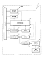
- FIG. 1 is a block diagram showing a configuration of an in-vehicle update system 1a according to the present embodiment.
- the power supply path is indicated by a thick solid line
- the signal transmission path is indicated by a broken line.
- 1 is a vehicle, and the vehicle 1 includes a battery 2, an IG relay 3, an ACC relay 4, a cigar socket 5, ECUs 6a and 6b, a display device 7, an operation device 8, and the like.
- the battery 2 is a device that stores electric power generated by an alternator (not shown) during engine operation of the vehicle 1, and can be configured using a battery such as a lead storage battery or a lithium ion battery.
- the battery 2 supplies the accumulated electric power to in-vehicle devices such as ECUs 6a and 6b mounted on the vehicle 1 while the engine of the vehicle 1 is stopped.
- the IG relay 3 is arranged in a power supply path from the battery 2 to an in-vehicle device such as the ECU 6a, and switches energization / cutoff of the power supply path.
- an in-vehicle device such as the ECU 6a
- switches energization / cutoff of the power supply path In FIG. 1, only one ECU 6a is connected to the IG relay 3.
- the IG relay 3 is switched between energization / interruption according to the state of an ignition switch (not shown) for performing an operation of switching the engine start of the vehicle 1 and the power supply state to the in-vehicle device.
- the IG relay 3 is switched so as to be in an energized state during the engine operation of the vehicle 1 and to be in a cut-off state when the engine is stopped.
- the ACC relay 4 is arranged in the power supply path from the battery 2 to the in-vehicle equipment such as the ECU 6b and the in-vehicle electrical components such as the cigar socket 5, and switches between energization / interruption of the power supply path.
- the present invention is not limited to this, and other in-vehicle devices or in-vehicle electrical components may be further connected.
- the ACC relay 4 is also switched between energization / interruption according to the state of the ignition switch of the vehicle 1. Switching between energization / cutoff of the IG relay 3 and switching between energization / cutoff of the ACC relay 4 are interlocked.
- the ACC relay 4 When the IG relay 3 is energized, the ACC relay 4 is energized, and the ACC relay 4 is When in the cut-off state, the IG relay 3 is cut off. However, it may exist when the IG relay 3 is in the cut-off state and the ACC relay 4 is in the energized state.
- the cigar socket 5 is a cigarette lighter socket provided near the driver's seat of the vehicle 1.
- the cigar socket 5 is not used for a cigar lighter but can be used as a connection part for supplying power to the outside, and in this case, it can also be called an accessory socket or a power socket.
- Various retrofit devices 99 can be connected to the cigar socket 5 via a power cable provided with a terminal called a so-called car plug. In the state where the retrofit device 99 is connected to the cigar socket 5, when the ACC relay 4 is switched to the energized state, power is supplied from the alternator of the vehicle 1 or the battery 2 to the retrofit device 99, and based on this power The retrofit device 99 can operate.
- the ECUs 6a and 6b are, for example, an ECU that controls the operation of the engine of the vehicle 1, an ECU that controls the locking / unlocking of the door, an ECU that controls the turning on / off of the light, an ECU that controls the operation of the airbag, and an ABS.
- Various ECUs such as an ECU that controls the operation of (Antilock Brake System) may be included.
- the ECUs 6a and 6b perform various processes by causing a CPU (Central Processing Unit) to execute a program stored in an internal memory or the like.
- the ECU 6 a is an ECU that can be an update process for updating a program stored in a memory or the like, and is connected to the battery 2 via the IG relay 3.
- the display device 7 is, for example, a liquid crystal display and displays a message or an image for the user of the vehicle 1.
- the operation device 8 is a device such as a push switch, a dial switch, or a touch panel disposed in the vicinity of the driver's seat of the vehicle 1 and is a device for receiving a user operation.
- the display device 7 and the operation device 8 may be shared with, for example, a car navigation device.
- the display device 7 and the operation device 8 are configured to receive power supply directly from the battery 2, but the present invention is not limited to this.
- the display device 7 and the operation device 8 may be configured to be connected to the battery 2 via the IG relay 3 or the ACC relay 4.
- the in-vehicle update system 1a includes an in-vehicle update device 10, a cigar relay 9, and the like.
- the in-vehicle update device 10 is a device that performs a process of updating a program or data (hereinafter simply referred to as a program) stored in a memory or the like of the ECU 6a.
- the in-vehicle update device 10 communicates with, for example, a server device outside the vehicle while the engine of the vehicle 1 is operating, inquires whether the program of the ECU 6a needs to be updated, and updates if necessary. Download the program for use and store it.
- the in-vehicle update device 10 When or before the engine of the vehicle 1 is stopped, the in-vehicle update device 10 displays a message notifying that the program of the ECU 6a needs to be updated on the display device 7 to inquire whether or not the update is possible.
- the device 8 accepts selection of whether or not to update from the user.
- the in-vehicle update device 10 stores the update program stored when the predetermined update timing is reached, for example, after a predetermined time has elapsed since the engine of the vehicle 1 is stopped. Update processing is performed by transmitting to the ECU 6a to be updated.
- the ECU 6 a to be updated in the present embodiment is connected to the battery 2 via the IG relay 3. While the engine of the vehicle 1 is stopped, the IG relay 3 is in a cut-off state, the electric power from the battery 2 is not supplied to the ECU 6a, and the ECU 6a cannot operate.
- the in-vehicle update device 10 can control switching of the IG relay 3 and the ACC relay 4, and when performing the update process of the ECU 6a, the IG relay 3 is switched to the energized state, thereby updating the object. ECU 6a in an operable state.
- the IG relay 3 and the ACC relay 4 are interlocked, and when the IG relay 3 is in an energized state, the ACC relay 4 is also in an energized state.
- the ACC relay 4 also switches to the energized state. Therefore, if the retrofit device 99 is connected to the cigar socket 5, when the in-vehicle update device 10 performs the update process, power is supplied from the battery 2 to the retrofit device 99.
- the retrofit device 99 is a device connected by the user according to his / her preference or necessity, and does not need to be operated for the update process of the ECU 6a, and does not need to supply the power of the battery 2 at all.
- a cigar relay 9 is provided in the power supply path from the ACC relay 4 to the cigar socket 5.
- the cigar relay 9 switches energization / cutoff of the power supply path in accordance with a control signal from the in-vehicle update device 10.
- the cigar relay 9 is arranged in the immediate vicinity of the cigar socket 5 and cuts off the power supply to the cigar socket 5.
- other in-vehicle devices such as the ECU 6b connected to the ACC relay 4 or in-vehicle electrical equipment The power supply to the product shall not be cut off.
- the cigar relay 9 is comprised using the latch relay which does not require electric power in order to maintain an energized state and a interruption
- the in-vehicle update device 10 completes the acquisition of the update program from the server device outside the vehicle, and starts the update process of the ECU 6a at a predetermined timing after the engine of the vehicle 1 is stopped. At this time, the in-vehicle update device 10 first performs control to switch the cigar relay 9 to the cutoff state. Next, the in-vehicle update device 10 performs control to switch the IG relay 3 and the ACC relay 4 to the energized state, and transmits a command to stop the operation to the ECU 6b that is not the target of the update process. Thereafter, the in-vehicle update device 10 performs the update process by transmitting the update program to the ECU 6a that is the target of the update process. After completion of the update process, the in-vehicle update device 10 performs control for switching the IG relay 3 and the ACC relay 4 to the cutoff state and performs control for switching the cigar relay 9 to the energized state.
- FIG. 2 is a block diagram showing a configuration of the in-vehicle update device 10 according to the present embodiment.
- the in-vehicle updating apparatus 10 includes a processing unit 11, a storage unit 12, an in-vehicle communication unit 13, a control signal output unit 14, and the like.
- the processing unit 11 is configured using an arithmetic processing unit such as a CPU (Central Processing Unit) or an MPU (Micro-Processing Unit), and reads and executes a program (not shown) stored in the storage unit 12. Thus, various arithmetic processes are performed.
- CPU Central Processing Unit
- MPU Micro-Processing Unit
- the processing unit 11 is a process for downloading an update program for the ECU 6a from a server device outside the vehicle, a process for inquiring the user whether the update process is possible, a process for updating the program by transmitting the downloaded update program to the ECU 6a, etc. I do. Moreover, in this Embodiment, the process part 11 performs the switching control process of the IG relay 3, the ACC relay 4, and the cigar relay 9 at the time of performing an update process.
- the storage unit 12 is configured using a non-volatile memory element such as a flash memory or an EEPROM (Electrically Erasable Programmable Read Only Memory).
- the storage unit 12 stores a program executed by the processing unit 11 and data necessary for executing the program, and stores an update program 12a used for updating the ECU 6a.
- the storage unit 12 may store data generated in the course of processing by the processing unit 11.
- the in-vehicle communication unit 13 is connected to a communication line constituting an in-vehicle network provided in the vehicle 1 and transmits and receives data according to a communication protocol such as CAN (Controller Area Network).
- the in-vehicle communication unit 13 transmits information by converting the data provided from the processing unit 11 into an electric signal and outputs the signal to the communication line, and receives the data by sampling and acquiring the potential of the communication line.
- the received data is given to the processing unit 11. Accordingly, the in-vehicle update device 10 can transmit and receive data to and from the ECUs 6a and 6b, the display device 7, and the operation device 8 mounted on the vehicle 1.
- the control signal output unit 14 is connected to the IG relay 3, the ACC relay 4, and the cigar relay 9 via signal lines and the like, and receives a control signal for switching energization / cutoff of these relays according to an instruction from the processing unit 11. Output.
- the in-vehicle update device 10 directly performs relay switching control.
- the present invention is not limited to this, and a separate ECU that performs relay switching control is provided. It is good also as a structure which the vehicle-mounted update apparatus 10 instruct
- switching control of the IG relay 3 and the ACC relay 4 according to the operation of the ignition switch of the vehicle is not performed by the in-vehicle update device 10, but another ECU (not shown) that performs switching control of the relay. Is omitted).
- the update processing unit 21, the switching control unit 22, and the like are realized as software functional blocks by executing the program stored in the storage unit 12.
- the update processing unit 21 performs processing for updating a program stored in a storage unit of various in-vehicle devices (ECU 6a in the present embodiment) mounted on the vehicle 1.
- the update processing unit 21 communicates with a server device outside the vehicle while the engine of the vehicle 1 is operating, and performs a process of inquiring whether there is a program update for all on-vehicle devices that may be updated.
- the update processing unit 21 acquires an update program necessary for the update process from the server device and stores the update program in the storage unit 12.
- the update processing unit 21 reads the update program 12a stored in the storage unit 12 and becomes an object of the update process. Update processing is performed by transmitting to the device.
- the switching control unit 22 performs energization / interruption switching control of the IG relay 3, the ACC relay 4, and the cigar relay 9 when performing the update process by the update processing unit 21.
- the switching control unit 22 gives an instruction for energization / cutoff of each relay to the control signal output unit 14, and the control signal output unit 15 outputs a control signal for switching energization / cutoff of each relay in response thereto.
- the switching control unit 22 first performs control to switch the cigar relay 9 to the cutoff state.
- the switching control unit 22 performs control to switch the IG relay 3 and the ACC relay 4 to the energized state.
- the update processing unit 21 may perform a process of reducing power consumption by the ECU 6b by giving an instruction to stop the operation and shift to the sleep state to the ECU 6b that is not the target of the update process.
- the switching control unit 22 performs control to switch the IG relay 3 and the ACC relay 4 from the energized state to the disconnected state.
- the switching control unit 22 performs control to switch the cigar socket 5 from the shut-off state to the energized state. Thereby, the switching control part 22 can switch each relay to the state before the start of the update process by the update process part 21.
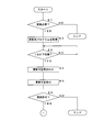
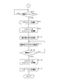
- 3 and 4 are flowcharts showing a procedure of processing performed by the in-vehicle update device 10 according to the present embodiment. Note that the processing shown in this flowchart starts from a state where the ignition switch of the vehicle 1 is on (that is, the engine of the vehicle 1 is operating). In this state, the IG relay 3, the ACC relay 4, and the cigar relay 9 of the vehicle 1 are in an energized state.
- the update processing unit 21 of the processing unit 11 of the in-vehicle update device 10 performs communication with a server device outside the vehicle using, for example, a wireless communication device mounted on the vehicle 1, and a program for the ECU 6 a mounted on the vehicle 1. It is determined whether or not the update process of the ECU 6a is necessary (step S1).
- the update processing unit 21 ends the process.
- the update processing unit 21 acquires an update program necessary for the update process from the server device (step S2), and stores the acquired update program in the storage unit 12. .
- the processing unit 11 determines whether or not the ignition switch of the vehicle 1 has been switched from the on state to the off state (step S3).
- the processing unit 11 waits until the ignition switch is switched to the off state.
- the processing unit 11 advances the processing to step S4. Note that the IG relay 3 and the ACC relay 4 are switched from the energized state to the cut-off state by switching the ignition switch to the off state.
- the update processing unit 21 of the processing unit 11 determines whether or not to permit the display device 7 to perform the update process of the ECU 6 by giving an instruction message display instruction to the display device 7 in the in-vehicle communication unit 13.
- a message to be inquired is displayed, and the user is inquired of whether or not update processing is possible (step S4).
- the message displayed at this time can be, for example, “ECU program needs to be updated. Are you sure you want to start the update from 11:00 pm today? (Yes / No)”.
- the update processing unit 21 accepts selection of whether or not the user can update the inquiry message displayed on the display device 7 by using the operation device 8 (step S5).
- the selection of whether or not update is accepted by the operation device 8 is transmitted to the in-vehicle update device 10 via the in-vehicle network, which is received by the in-vehicle communication unit 13 and given to the processing unit 11.
- the update processing unit 21 determines whether or not permission to perform the update process of the ECU 6a has been obtained based on the content received in step S5 (step S6). When the permission of the update process is not obtained (S6: NO), the update processing unit 21 ends the process without performing the update process.
- the update processing unit 21 determines whether or not a predetermined timing for performing the update process has been reached (step S7).
- a predetermined time for example, a predetermined time such as 11:00 pm, or a timing after two hours have elapsed since the ignition switch is switched to the off state can be employed.
- the update timing may be determined by the user.
- the update processing unit 21 stands by until the update timing is reached.
- the switching control unit 22 of the processing unit 11 switches the cigar relay 9 from the energized state to the disconnected state (step S8). Thereafter, the switching control unit 22 switches the IG relay 3 and the ACC relay 4 from the disconnected state to the energized state (step S9). Further, the update processing unit 21 of the processing unit 11 transmits an operation stop command to the ECU 6b that is not an update processing target in the in-vehicle communication unit 13 (step S10).
- the update processing unit 21 performs the update process by reading the update program 12a stored in the storage unit 12 and transmitting it to the ECU 6a to be updated by the in-vehicle communication unit 13 (step S11).
- the update processing unit 21 determines whether or not the transmission of the update program 12a is completed and the update process of the ECU 6a is completed (step S12).
- the update processing unit 21 returns the process to step S11 and continues to transmit the update program 12a.
- the switching control unit 22 switches the IG relay 3 and the ACC relay 4 from the energized state to the energized state (step S13). Thereafter, the switching control unit 22 switches the cigar relay 9 from the cut-off state to the energized state (step S14) and ends the process.
- the in-vehicle update device 10 installed in the vehicle 1 performs update processing of a program stored in the memory of the ECU 6a.
- the vehicle 1 is equipped with in-vehicle devices such as an ECU 6a that are subject to update processing and in-vehicle electrical components such as cigar sockets 5 that are not subject to update processing, and these are supplied with electric power from the battery 2 of the vehicle 1. Supplied.
- a cigar relay 9 is provided in the power supply path from the battery 2 to the cigar socket 5, and when the in-vehicle update device 10 performs the update process of the ECU 6a, the cigar relay 9 is controlled to be switched to a cut-off state.
- power is not supplied from the battery 2 to the cigar socket 5 (the retrofitted device 99 connected thereto) during the update process of the ECU 6a, so that a decrease in the stored power amount of the battery 2 can be suppressed.
- the in-vehicle update system 1a performs an update process of the ECU 6a when the engine of the vehicle 1 is stopped. Thereby, the update process of ECU6a can be performed safely, without affecting the driving
- the IG relay 3 is arranged in the power supply path from the battery 2 to the ECU 6a, and the ACC relay 4 is arranged in the power supply path from the battery 2 to the cigar relay 9.
- the in-vehicle update device 10 switches the IG relay 3 and the ACC relay 4 to the energized state when performing the update process. Thereby, the update process of ECU6a at the time of the engine stop of the vehicle 1 is realizable.
- the in-vehicle update system 1a has a vehicle-mounted electrical component that cuts off the power supply during the update process as a connection unit that can removably attach the retrofit device 99 via a feeder line or the like.
- the cigar socket 5 is used. Since the user of the vehicle 1 can connect an arbitrary retrofit device 99 to the cigar socket 5, the retrofit device 99 with excessive power consumption accompanying the operation is connected, and the battery is exhausted by the update process. May occur. By shutting off the power supply to the cigar socket 5 with the cigar relay 9, no matter what retrofit device 99 is connected to the cigar socket 5, the battery does not run out. Update processing can be performed.
- the in-vehicle update device 10 performs switching between energization / cutoff by the cigar relay 9. Since the in-vehicle update device 10 is a device that performs an update process such as the ECU 6a, it is possible to easily and appropriately switch the cigar relay 9 according to the update process.
- the dedicated in-vehicle update device 10 is provided in the system as a device for updating the program of the ECU 6a.
- the gateway device mounted on the vehicle 1 or any ECU may be configured to perform the update process.
- the in-vehicle update device 10 is configured to inquire the user of the vehicle 1 whether or not the update process is possible before performing the update process.
- the present invention is not limited to this.
- the in-vehicle update device 10 may be configured to perform the update process when the update timing is reached without inquiring whether the update process is possible.
- the system configuration shown in FIG. 1 is an example, and the present invention is not limited to this.
- the ECU 6 a to be updated may be connected to the battery 2 via the ACC relay 4 instead of being connected to the battery 2 via the IG relay 3.
- the cigar socket 5 may be connected to the battery 2 via the IG relay 3 instead of being connected to the battery 2 via the ACC relay 4.
- both the ECU 6a and the cigar socket 5 may be connected to the battery 2 via a common relay (IG relay 3 or ACC relay 4).
- the cigar relay 9 is arranged in the power supply path from the IG relay 3 or the ACC relay 4 to the cigar socket 5, and the electric power to the cigar socket 5 is set by turning off the cigar relay 9. Any configuration that cuts off the supply and does not cut off the supply of electric power to the ECU 6a may be used.
- the in-vehicle electrical component that cuts off the power supply during the update process is the cigar socket 5, but the present invention is not limited to this.
- the in-vehicle electrical component may be a USB standard connection unit to which power is supplied via the USB cable, to which the retrofit device 99 is detachably connected via a USB (UniversalUSBSerial Bus) cable, for example.
- a connection part having a configuration other than the cigar socket 5 and the USB standard connection part may be used.
- the in-vehicle electrical component is not limited to a connection part for connecting the retrofit device 99.
- the vehicle-mounted electrical component can be controlled by the user directly on / off of the power to the vehicle 1 by a switch operation or the like, but the vehicle-mounted update device 10 cannot give an operation stop command or the like by in-vehicle communication or the like. It may be a device.
- the in-vehicle update system 1a has a configuration in which the in-vehicle update device 10 that performs update processing of the ECU 6a performs switching control of energization / cutoff of the cigar relay 9, but is not limited thereto.
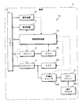
- FIG. 5 is a block diagram illustrating a configuration of the in-vehicle update system 1a according to the first modification.
- the operation device 8 performs energization / cutoff switching control of the cigar relay 9.
- the operation device 8 performs a process of accepting selection of whether or not update is possible from the user in response to an inquiry as to whether or not to perform the update process by the in-vehicle update device 10.
- the controller device 8 according to the first modification performs a process of switching the cigar relay 9 from the energized state to the cut-off state when receiving a selection for permitting the update process. Further, the operation device 8 shuts off the cigar relay 9 when, for example, the ignition switch of the vehicle 1 is switched from an off state to an on state, or when an update processing completion notification is given from the in-vehicle update device 10. The process to switch from to the energized state is performed.
- the switching control of energization / cutoff of the cigar relay 9 may be performed by a device other than the in-vehicle update device 10 or the operation device 8.
- a device that performs switching control of the IG relay 3 and the ACC relay 4 according to switching of the ignition switch of the vehicle 1 performs switching control of energization / cutoff of the cigar relay 9 according to an instruction from the in-vehicle update device 10 can do.
- FIG. 6 is a block diagram illustrating a configuration of the in-vehicle update system 1a according to the second modification.
- the in-vehicle update system 1a according to the second modification uses the semiconductor fuse 109 as the cigar relay 9.
- the semiconductor fuse 109 controls a semiconductor element such as a MOSFET (Metal Oxide Semiconductor Field Effect Transistor) disposed in the power supply path and performs switching control of energization / cutoff of the semiconductor element by detecting the amount of current flowing through the semiconductor element.
- IC Integrated Circuit
- the semiconductor fuse 109 can perform switching control of energization / cutoff of the semiconductor element in accordance with a switching signal of energization / cutoff given from the in-vehicle update device 10.
- FIG. 7 is a schematic diagram for explaining the semiconductor fuse 109 according to the second modified example, and shows a power supply path from the battery 2 of the vehicle 1 to the cigar socket 5 through the ACC relay 4. .
- the upper part of FIG. 7 illustrates the configuration of a conventional vehicle.
- the fuse 110 is provided in the power supply path between the ACC relay 4 and the cigar socket 5.
- the fuse 110 is blown by the overcurrent flowing and interrupts the power supply path, thereby preventing the overcurrent from flowing to the retrofit device 99 connected to the cigar socket 5.
- FIG. 7 shows the configuration of the in-vehicle update system 1a according to the above-described embodiment.
- a cigar relay 9 is added between the ACC relay 4 and the fuse 110 with respect to the conventional configuration, and the in-vehicle update device 10 performs energization / interruption switching control of the cigar relay 9. Do. If an overcurrent flows through the fuse 110 while the cigar relay 9 is energized, the fuse 110 is blown and the power supply path is interrupted.
- the power is supplied from the battery 2 to the retrofit device 99 connected to the cigar socket 5 during the update process by switching the cigar relay 9 to the cut-off state. To prevent that.
- the in-vehicle update system 1a according to the modified example 2 has a configuration in which the cigar relay 9 and the fuse 110 in the system configuration shown in the middle stage of FIG.
- the semiconductor fuse 109 includes a MOSFET 109a arranged in the power supply path between the ACC relay 4 and the cigar socket 5, and a control IC 109b that performs switching control of energization / cutoff of the MOSFET 109a.
- the control IC 109b detects the current flowing through the MOSFET 109a, and switches the MOSFET 109a from the energized state to the cut-off state when, for example, the detected current amount exceeds a threshold value.
- control IC 109b switches the MOSFET 109a from the energized state to the cut-off state in response to the cut-off command given from the in-vehicle update device 10. Therefore, the MOSFET 109a is in a cut-off state when the control IC 109b detects an overcurrent and when the in-vehicle update device 10 outputs a cut-off command, and is in an energized state in other cases.
- the in-vehicle update system 1a is configured to use the semiconductor fuse 109 as the cigar relay 9.
- the semiconductor fuse 109 is a circuit element having both the function of the fuse 110 provided in the power supply path from the ACC relay 4 to the cigar socket 5 and the function of the cigar relay 9, so that it is not necessary to provide the fuse 110, and the in-vehicle
- the number of parts such as circuit elements constituting the update system 1a can be reduced.
Landscapes
- Engineering & Computer Science (AREA)
- Theoretical Computer Science (AREA)
- General Engineering & Computer Science (AREA)
- Software Systems (AREA)
- General Physics & Mathematics (AREA)
- Physics & Mathematics (AREA)
- Mechanical Engineering (AREA)
- Computer Security & Cryptography (AREA)
- Power Engineering (AREA)
- Quality & Reliability (AREA)
- Automation & Control Theory (AREA)
- Stored Programmes (AREA)
- Charge And Discharge Circuits For Batteries Or The Like (AREA)
Abstract
車載機器の更新処理に伴うバッテリ上がりを抑制し得る車載更新システム及び車載更新装置を提供する。 本実施の形態に係る車載更新システムは、車両に搭載されたバッテリと、前記バッテリからの電力が供給され、記憶部に記憶されたプログラムを実行して動作する車載機器と、前記バッテリからの電力が供給される車載電装品と、前記バッテリから前記車載電装品への電力供給経路中に配され、前記電力供給経路の通電/遮断を切り替える第1のリレーと、前記車載機器の前記記憶部に記憶されたプログラムを更新する処理を行う更新処理部を有する車載更新装置と、前記更新処理部が更新処理を行う際に前記第1のリレーを遮断状態へ切り替える切替制御部とを備える。
Description
本発明は、車両に搭載された車載機器のプログラムを更新する車載更新システム及び車載更新装置に関する。
従来、車両には複数のECU(Electronic Control Unit)などの車載機器が搭載され、複数のECUがCAN(Controller Area Network)バスなどの通信線を介して接続されて相互に情報の送受信を行うことが可能とされている。各ECUは、フラッシュメモリ又はEEPROM(Electrically Erasable Programmable Read Only Memory)等の記憶部に記憶されたプログラムをCPU(Central Processing Unit)などの処理装置が読み出して実行することにより、車両の制御などの種々の処理を行っている。ECUの記憶部に記憶されたプログラム又はデータは、例えば機能追加、不具合の修正又はバージョンアップ等の必要が生じた際には、新たなプログラム又はデータに書き換える更新処理を行う必要がある。この場合、更新処理の対象となるECUに対して、通信線を介して更新用のプログラム又はデータを送信することが行われている。
特許文献1においては、エンジン起動中でドライバが降車した後にプログラムを更新する場合に、プログラム更新装置が車両状態を監視してセンタに監視情報を送信し、センタがプログラム更新中の車両の状態を監視するプログラム更新システムが提案されている。
特許文献1に記載のプログラム更新システムでは、車両のエンジン起動中にプログラムの更新が行われる。しかしながら、ユーザが車両を使用しない可能性の高いエンジン停止中にプログラムの更新を行うことが望まれる場合があり得る。エンジン停止中にプログラムの更新を行う場合、車両のバッテリに蓄積された電力を用いて更新対象となるECUを動作させる必要がある。このため、更新対象のECUが例えばIG(イグニッション)リレー又はACC(アクセサリ)リレー等のリレーを介してバッテリに接続されている場合、プログラムの更新を行う際にはリレーを導通状態へ切り替える制御が行われる。
このようなリレーの導通制御を行うことによって、このリレー又はこのリレーに連動する別のリレーに接続された更新処理対象ではないECU又は他の電装品等へもバッテリから電力が供給されることとなる。更新処理対象ではないECUに対しては、例えば車内ネットワークを介して動作停止命令を送信することによって、動作を停止させることが可能である。しかしながらこのような動作停止を行うことができない電装品が存在する場合、更新処理中にこの電装品によって電力が消費されバッテリ上がりが発生する虞がある。電装品が、例えば車両のシガーソケットのように、ユーザが任意の機器を接続することができる接続部である場合、接続部に接続された機器がどの程度の電力を消費するものであるかを事前に見積もることは困難である。
本発明は、斯かる事情に鑑みてなされたものであって、その目的とするところは、車載機器の更新処理に伴うバッテリ上がりを抑制し得る車載更新システム及び車載更新装置を提供することにある。
本発明に係る車載更新システムは、車両に搭載されたバッテリからの電力が供給され、記憶部に記憶されたプログラムを実行して動作する車載機器と、前記バッテリから前記車両に搭載された車載電装品への電力供給経路中に配され、前記電力供給経路の通電/遮断を切り替える第1のリレーと、前記車載機器の前記記憶部に記憶されたプログラムを更新する処理を行う更新処理部を有する車載更新装置と、前記更新処理部が更新処理を行う際に前記第1のリレーを遮断状態へ切り替える切替制御部とを備えることを特徴とする。
また、本発明に係る車載更新システムは、前記更新処理部が、前記車両のエンジン停止時に更新処理を行うことを特徴とする。
また、本発明に係る車載更新システムは、前記バッテリから車載機器までの電力供給経路中に配され、該電力供給経路の通電/遮断を切り替える第2のリレーと、前記バッテリから前記第1のリレーまでの電力供給経路中に配され、該電力供給経路の通電/遮断を切り替える第3のリレーとを備え、前記切替制御部は、前記更新処理部が更新を行う際に前記第2のリレー及び前記第3のリレーを通電状態へ切り替えることを特徴とする。
また、本発明に係る車載更新システムは、前記第1のリレーを、半導体ヒューズを用いて構成してあることを特徴とする。
また、本発明に係る車載更新システムは、前記車載電装品が、着脱可能に給電線を接続可能な接続部であることを特徴とする。
また、本発明に係る車載更新システムは、前記接続部はシガーソケットであることを特徴とする。
また、本発明に係る車載更新システムは、前記車載更新装置が、前記切替制御部を有することを特徴とする。
また、本発明に係る車載更新装置は、車両に搭載されたバッテリからの電力が供給されて動作する車載機器の記憶部に記憶されたプログラムを更新する処理を行う更新処理部と、前記バッテリから前記車両に搭載された車載電装品への電力供給経路中に配された第1のリレーを、前記更新処理部が更新処理を行う際に遮断状態へ切り替える切替制御部とを備えることを特徴とする。
本発明においては、車載更新装置が車載機器の記憶部に記憶されたプログラムの更新処理を行う。車両には更新処理の対象となる車載機器と、更新処理の対象とならない車載電装品とが搭載されており、これらには車両のバッテリからの電力が供給される。バッテリから車載電装品までの電力供給経路には第1のリレーを設け、車載更新装置が車載機器の更新処理を行う際に、第1のリレーを遮断状態へと切り替える。これにより車載機器の更新処理の際にバッテリから車載電装品へ電力が供給されなくなるため、バッテリの蓄積電力量の低下を抑制できる。
また本発明においては、車両のエンジン停止時に車載機器の更新処理を車載更新装置が行う。これにより、車両の走行に影響を与えることなく、車載機器の更新処理を安全に行うことができる。
また本発明においては、バッテリから車載機器までの電力供給経路中に第2のリレーが配され、バッテリから第1のリレーまでの電力供給経路中に第3のリレーが配される。第2のリレー及び第3のリレーは、例えばIGリレー又はACCリレー等と呼ばれ得るものであってよい。車両のエンジン停止時にはこれらのリレーは遮断状態とされるが、車載更新装置が更新処理を行う際にこれらのリレーを通電状態へ切り替えることによって、車両のエンジン停止時の更新処理を実現できる。
また本発明においては、半導体ヒューズを用いて第1のリレーを構成する。バッテリから車載電装品までの電力供給経路中には、過電流を防止するためのヒューズが設けられるが、半導体ヒューズを用いることでこの過電流防止用のヒューズと第1のリレーとを兼ねることができるため、部品点数を削減することができる。
また本発明においては、第1のリレーにて更新処理時の電力供給を遮断する車載電装品は、着脱可能に給電線を接続することが可能な接続部、例えばシガーソケットとすることができる。このような接続部に対しては車両の乗員が任意の装置を接続することができるため、動作に伴う消費電力量が過大な装置が接続され、更新処理によってバッテリ上がりが生じる虞がある。このような接続部への電力供給を遮断することによって、接続部にどのような装置が接続されている場合であっても、バッテリ上がりを生じさせることなく更新処理を行うことができる。
また本発明においては、第1のリレーによる通電/遮断の切り替えを車載更新装置が行う。車載更新装置は、車載機器の更新処理を行う装置であるため、更新処理に応じた第1のリレーの切り替えを容易且つ適切に行うことができる。
本発明による場合は、車載機器の更新処理を行う際に、バッテリから車載電装品までの電力供給経路に設けた第1のリレーを遮断状態へと切り替える構成とすることにより、車載機器の更新処理の際にバッテリから車載電装品への電力供給を遮断し、車載機器の更新処理に伴うバッテリ上がりを抑制することができる。
図1は、本実施の形態に係る車載更新システム1aの構成を示すブロック図である。なお本図においては、電力供給経路を太実線で示し、信号伝達経路を破線で示してある。また図において一点鎖線で示す1は車両であり、車両1にはバッテリ2、IGリレー3、ACCリレー4、シガーソケット5、ECU6a,6b、表示装置7及び操作装置8等が備えられている。バッテリ2は、車両1のエンジン動作中にオルタネータ(図示は省略する)が発電した電力を蓄積する装置であり、例えば鉛蓄電池又はリチウムイオン電池等の電池を用いて構成することができる。バッテリ2は、車両1のエンジン停止中には、車両1に搭載されたECU6a,6bなどの車載機器へ、蓄積した電力を供給する。
IGリレー3は、バッテリ2からECU6aなどの車載機器への電力供給経路中に配され、電力供給経路の通電/遮断を切り替える。なお図1においては、IGリレー3に1つのECU6aのみが接続されているが、これに限るものではなく、複数の車載機器が接続されていてよい。IGリレー3は、車両1のエンジン始動及び車載機器への電力供給状態を切り替える操作を行うためのイグニッションスイッチ(図示は省略する)の状態に応じて通電/遮断が切り替えられる。IGリレー3は、車両1のエンジン動作中に通電状態となり、エンジン停止中には遮断状態となるよう切り替えが行われる。
ACCリレー4は、バッテリ2からECU6bなどの車載機器とシガーソケット5などの車載電装品とへの電力供給経路中に配され、電力供給経路の通電/遮断を切り替える。なお図1においては、ACCリレー4に1つのECU6b及びシガーソケット5のみが接続されているが、これに限るものではなく、他の車載機器又は車載電装品が更に接続されていてよい。ACCリレー4もまた、車両1のイグニッションスイッチの状態に応じて通電/遮断が切り替えられる。IGリレー3の通電/遮断の切り替えと、ACCリレー4の通電/遮断の切り替えとは連動しており、IGリレー3が通電状態である場合にはACCリレー4は通電状態となり、ACCリレー4が遮断状態である場合にはIGリレー3は遮断状態となる。ただしIGリレー3が遮断状態且つACCリレー4が通電状態の場合は存在し得る。
シガーソケット5は、車両1の運転席近傍に設けられたシガーライター用のソケットである。ただしシガーソケット5は、シガーライターのために用いるのではなく、外部への電力供給用の接続部として用いることができ、この場合にはアクセサリソケット又は電源ソケット等とも呼ばれ得る。シガーソケット5には、いわゆるカープラグと呼ばれる端子が設けられた電源ケーブルを介して様々な後付デバイス99を接続することができる。シガーソケット5に後付デバイス99が接続された状態において、ACCリレー4が通電状態に切り替えられた場合、車両1のオルタネータ又はバッテリ2から後付デバイス99へ電力が供給され、この電力に基づいて後付デバイス99が動作することができる。
ECU6a,6bは、例えば車両1のエンジンの動作を制御するECU、ドアのロック/アンロックを制御するECU、ライトの点灯/消灯を制御するECU、エアバッグの動作を制御するECU、及び、ABS(Antilock Brake System)の動作を制御するECU等の種々のECUが含まれ得る。ECU6a,6bは、内部のメモリなどに記憶されたプログラムをCPU(Central Processing Unit)などが実行することによって、種々の処理を行う。本実施の形態においてはECU6aが、メモリなどに記憶されたプログラムを更新する更新処理の対象となり得るECUであり、IGリレー3を介してバッテリ2に接続されている。
表示装置7は、例えば液晶ディスプレイなどであり、車両1のユーザに対するメッセージ又は画像等の表示を行う。操作装置8は、車両1の運転席近傍に配されたプッシュスイッチ、ダイヤルスイッチ又はタッチパネル等の装置であり、ユーザの操作を受け付けるための装置である。なお表示装置7及び操作装置8は、例えばカーナビゲーション装置と共用のものであってよい。また本実施の形態においては、表示装置7及び操作装置8が直接的にバッテリ2からの電力供給を受ける構成としてあるが、これに限るものではない。表示装置7及び操作装置8は、IGリレー3又はACCリレー4を介してバッテリ2に接続される構成であってもよい。
また本実施の形態に係る車載更新システム1aは、車載更新装置10及びシガーリレー9等を備えている。車載更新装置10は、ECU6aのメモリなどに記憶されたプログラム又はデータ等(以下、単にプログラムという)を更新する処理を行う装置である。車載更新装置10は、車両1のエンジン動作中に例えば車外のサーバ装置との間で通信を行い、ECU6aのプログラムの更新が必要であるか否かを問い合せ、更新が必要である場合には更新用のプログラムをダウンロードして記憶しておく。車両1のエンジンが停止された際又はその前に、車載更新装置10は、ECU6aのプログラムの更新が必要である旨を通知するメッセージを表示装置7に表示させて更新の可否を問合わせ、操作装置8にて更新の可否の選択をユーザから受け付ける。更新の許可が得られた場合、車載更新装置10は、例えば車両1のエンジン停止から所定時間が経過した後など、所定の更新タイミングに至った際に、記憶しておいた更新用のプログラムを更新対象のECU6aへ送信することによって、更新処理を行う。
ただし本実施の形態において更新対象となるECU6aは、IGリレー3を介してバッテリ2に接続されている。車両1のエンジン停止中にはIGリレー3は遮断状態となっており、ECU6aへはバッテリ2からの電力が供給されておらず、ECU6aは動作することができない。本実施の形態に係る車載更新装置10は、IGリレー3及びACCリレー4の切り替えを制御することができ、ECU6aの更新処理を行う際にはIGリレー3を通電状態へ切り替えることにより、更新対象のECU6aを動作可能な状態とする。
ただし上述のようにIGリレー3及びACCリレー4は連動しており、IGリレー3が通電状態である場合には、ACCリレー4も通電状態となる。車載更新装置10がECU6aの更新処理を行うためにIGリレー3を通電状態へ切り替えた場合、ACCリレー4も通電状態へ切り替わる。このためシガーソケット5に後付デバイス99が接続された状態であれば、車載更新装置10が更新処理を行う際に、バッテリ2から後付デバイス99への電力供給が行われることとなる。後付デバイス99は、ユーザが自身の好み又は必要性に応じて接続した装置であり、ECU6aの更新処理のために動作させる必要は全くなく、バッテリ2の電力を供給する必要は全くない。
そこで本実施の形態においては、ACCリレー4からシガーソケット5までの電力供給経路中にシガーリレー9を設ける。シガーリレー9は、この電力供給経路の通電/遮断の切り替えを、車載更新装置10からの制御信号に応じて行う。なお本実施の形態において、シガーリレー9は、シガーソケット5の直近に配され、シガーソケット5に対する電力供給の遮断を行うが、ACCリレー4に接続されたECU6bなどの他の車載機器又は車載電装品に対する電力供給の遮断は行わないものとする。またシガーリレー9は、通電状態及び遮断状態を維持するために電力を必要としないラッチリレーを用いて構成されることが好ましい。
車載更新装置10は、車外のサーバ装置から更新用プログラムの取得を完了し、車両1のエンジンが停止された後の所定のタイミングでECU6aの更新処理を開始する。このとき車載更新装置10は、まずシガーリレー9を遮断状態に切り替える制御を行う。次いで車載更新装置10は、IGリレー3及びACCリレー4を通電状態に切り替える制御を行うと共に、更新処理の対象ではないECU6bに対して動作を停止する命令を送信する。その後に車載更新装置10は、更新処理の対象であるECU6aに対して更新用プログラムを送信することによって更新処理を行う。更新処理の完了後、車載更新装置10は、IGリレー3及びACCリレー4を遮断状態に切り替える制御を行うと共に、シガーリレー9を通電状態へ切り替える制御を行う。
図2は、本実施の形態に係る車載更新装置10の構成を示すブロック図である。本実施の形態に係る車載更新装置10は、処理部11、記憶部12、車内通信部13及び制御信号出力部14等を備えて構成されている。処理部11は、例えばCPU(Central Processing Unit)又はMPU(Micro-Processing Unit)等の演算処理装置を用いて構成され、記憶部12に記憶されたプログラム(図示は省略する)を読み出して実行することにより、種々の演算処理を行う。処理部11は、車外のサーバ装置からECU6aの更新用プログラムをダウンロードする処理、更新処理の可否をユーザに問い合わせる処理、及び、ダウンロードした更新用プログラムをECU6aへ送信することでプログラムを更新する処理等を行う。また本実施の形態において処理部11は、更新処理を行う際のIGリレー3、ACCリレー4及びシガーリレー9の切替制御処理などを行う。
記憶部12は、フラッシュメモリ又はEEPROM(Electrically Erasable Programmable Read Only Memory)等の不揮発性のメモリ素子を用いて構成されている。記憶部12は、処理部11が実行するプログラム及びこのプログラムの実行に必要なデータなどを記憶すると共に、ECU6aの更新に用いられる更新用プログラム12aを記憶する。また記憶部12は、処理部11の処理の過程で生成されたデータなどを記憶してもよい。
車内通信部13は、車両1内に設けられた車内ネットワークを構成する通信線に接続され、例えばCAN(Controller Area Network)などの通信プロトコルに従ってデータの送受信を行う。車内通信部13は、処理部11から与えられたデータを電気信号に変換して通信線へ出力することによって情報を送信すると共に、通信線の電位をサンプリングして取得することによりデータを受信し、受信したデータを処理部11へ与える。これにより車載更新装置10は、車両1に搭載されたECU6a,6b、表示装置7及び操作装置8との間でデータの送受信を行うことができる。
制御信号出力部14は、信号線などを介してIGリレー3、ACCリレー4及びシガーリレー9にそれぞれ接続され、処理部11からの指示に応じてこれらのリレーの通電/遮断を切り替える制御信号を出力する。なお本実施の形態においては、車載更新装置10が直接的にリレーの切り替え制御を行う構成とするが、これに限るものではなく、リレーの切り替え制御を行うECUを別に設け、このECUに対して車載更新装置10がリレーの切り替えを指示する構成としてもよい。また本実施の形態においても、車両のイグニッションスイッチの操作に応じたIGリレー3及びACCリレー4の切り替え制御は、車載更新装置10が行うのではなく、リレーの切り替え制御を行う別のECU(図示は省略する)が行うものとする。
また処理部11には、記憶部12に記憶されたプログラムが実行されることによって、更新処理部21及び切替制御部22等がソフトウェア的な機能ブロックとして実現される。更新処理部21は、車両1に搭載された種々の車載機器(本実施の形態においてはECU6a)の記憶部に記憶されたプログラムを更新するための処理を行う。更新処理部21は、車両1のエンジン動作中に車外のサーバ装置との通信を行い、更新処理が行われる可能性がある全ての車載機器について、プログラムの更新の有無を問い合わせる処理を行う。更新処理部21は、更新処理を行う必要があるとの応答がサーバ装置から与えられた場合、更新処理に必要な更新用プログラムをサーバ装置から取得して記憶部12に記憶する。車両1のエンジンが停止状態となった後、更新処理を行う所定のタイミングに至った場合、更新処理部21は、記憶部12に記憶きた更新用プログラム12aを読み出して更新処理の対象となる車載機器へ送信することによって更新処理を行う。
切替制御部22は、更新処理部21による更新処理を行う際に、IGリレー3、ACCリレー4及びシガーリレー9の通電/遮断の切替制御を行う。切替制御部22は、制御信号出力部14に対して各リレーの通電/遮断の指示を与え、これに応じて制御信号出力部15が各リレーの通電/遮断を切り替える制御信号を出力する。更新処理部21が更新処理を開始する際、切替制御部22は、まずシガーリレー9を遮断状態へ切り替える制御を行う。次いで切替制御部22は、IGリレー3及びACCリレー4を通電状態へ切り替える制御を行う。これにより更新処理の対象であるECU6aへバッテリ2からの電力が供給されるが、シガーソケット5への電力供給を遮断することができる。なおこのときに更新処理部21は、更新処理対象ではないECU6bに対して、動作を停止してスリープ状態へ遷移する命令を与えることによって、ECU6bによる電力消費を低減する処理を行ってよい。
また更新処理部21が更新処理を完了した後、切替制御部22は、IGリレー3及びACCリレー4を通電状態から遮断状態へ切り替える制御を行う。次いで切替制御部22は、シガーソケット5を遮断状態から通電状態へ切り替える制御を行う。これにより切替制御部22は、更新処理部21による更新処理の開始前の状態へ、各リレーを切り替えることができる。
図3及び図4は、本実施の形態に係る車載更新装置10が行う処理の手順を示すフローチャートである。なお本フローチャートに示す処理は、車両1のイグニッションスイッチがオン(即ち車両1のエンジン動作中)の状態から開始するものとしてある。この状態において、車両1のIGリレー3、ACCリレー4及びシガーリレー9は、それぞれ通電状態とされている。車載更新装置10の処理部11の更新処理部21は、例えば車両1に搭載された無線通信装置を利用して車外のサーバ装置との間で通信を行い、車両1に搭載されたECU6aのプログラムの更新の有無を問い合わせることによって、ECU6aの更新処理が必要であるか否かを判定する(ステップS1)。更新処理が必要ない場合(S1:NO)、更新処理部21は、処理を終了する。更新処理が必要な場合(S1:YES)、更新処理部21は、サーバ装置から更新処理に必要な更新用プログラムを取得して(ステップS2)、取得した更新用プログラムを記憶部12に記憶する。
次いで処理部11は、車両1のイグニッションスイッチがオン状態からオフ状態へ切り替えられたか否かを判定する(ステップS3)。イグニッションスイッチがオフ状態に切り替えられておらず、オン状態である場合(S3:NO)、処理部11は、イグニッションスイッチがオフ状態へ切り替えられるまで待機する。イグニッションスイッチがオン状態からオフ状態へ切り替えられた場合(S3:YES)、処理部11は、ステップS4へ処理を進める。なおイグニッションスイッチがオフ状態へ切り替えられることによって、IGリレー3及びACCリレー4は通電状態から遮断状態へと切り替えられる。
次いで処理部11の更新処理部21は、車内通信部13にて表示装置7へ問合わせメッセージの表示指示を与えることによって、表示装置7にECU6の更新処理を行うことを許可するか否かを問い合わせるメッセージを表示し、ユーザに更新処理の可否を問い合せる(ステップS4)。このときに表示するメッセージは、例えば「ECUのプログラムを更新する必要があります。本日の午後11時から更新を開始してもよろしいですか?(はい/いいえ)」などとすることができる。更新処理部21は、表示装置7に表示した問合わせメッセージに対するユーザの更新可否の選択を、操作装置8にて受け付ける(ステップS5)。操作装置8にて受け付けられた更新可否の選択は、車内ネットワークを介して車載更新装置10へ送信され、これが車内通信部13にて受信されて処理部11へ与えられる。更新処理部21は、ステップS5にて受け付けた内容に基づいて、ECU6aの更新処理を行う許可が得られたか否かを判定する(ステップS6)。更新処理の許可が得られなかった場合(S6:NO)、更新処理部21は、更新処理を行わずに処理を終了する。
更新の許可が得られた場合(S6:YES)、更新処理部21は、更新処理を行うべき所定のタイミングに至ったか否かを判定する(ステップS7)。所定の更新タイミングは、例えば午後11時などの所定時刻、又は、イグニッションスイッチがオフ状態へ切り替えられてから2時間が経過した後等のタイミングを採用することができる。この更新タイミングをユーザが決定可能な構成としてもよい。更新タイミングに至っていない場合(S7:NO)、更新処理部21は、更新タイミングに至るまで待機する。
更新タイミングに至った場合(S7:YES)、処理部11の切替制御部22は、シガーリレー9を通電状態から遮断状態へ切り替える(ステップS8)。その後、切替制御部22は、IGリレー3及びACCリレー4を遮断状態から通電状態へ切り替える(ステップS9)。また処理部11の更新処理部21は、車内通信部13にて更新処理対象ではないECU6bへ、動作停止命令を送信する(ステップS10)。
更新処理部21は、記憶部12に記憶された更新用プログラム12aを読み出し、車内通信部13にて更新対象のECU6aへ送信することによって更新処理を行う(ステップS11)。更新処理部21は、更新用プログラム12aの送信が終了し、ECU6aの更新処理が完了したか否かを判定する(ステップS12)。更新処理が完了していない場合(S12:NO)、更新処理部21は、ステップS11へ処理を戻し、更新用プログラム12aの送信を継続して行う。更新処理が完了した場合(S12:YES)、切替制御部22は、IGリレー3及びACCリレー4を通電状態から遮断状態から通電状態へ切り替える(ステップS13)。その後、切替制御部22は、シガーリレー9を遮断状態から通電状態へ切り替えて(ステップS14)、処理を終了する。
以上の構成の本実施の形態に係る車載更新システム1aは、車両1に搭載された車載更新装置10がECU6aのメモリなどに記憶されたプログラムの更新処理を行う。車両1には更新処理の対象となるECU6aなどの車載機器と、更新処理の対象とならないシガーソケット5などの車載電装品とが搭載されており、これらには車両1のバッテリ2からの電力が供給される。バッテリ2からシガーソケット5までの電力供給経路にはシガーリレー9を設け、車載更新装置10がECU6aの更新処理を行う際に、シガーリレー9を遮断状態へと切り替える制御を行う。これによりECU6aの更新処理の際にバッテリ2からシガーソケット5(に接続された後付デバイス99)へ電力が供給されなくなるため、バッテリ2の蓄積電力量の低下を抑制できる。
また本実施の形態に係る車載更新システム1aは、車両1のエンジン停止時にECU6aの更新処理を行う。これにより、車両1の走行に影響を与えることなく、ECU6aの更新処理を安全に行うことができる。
また本実施の形態に係る車載更新システム1aは、バッテリ2からECU6aまでの電力供給経路中にIGリレー3が配され、バッテリ2からシガーリレー9までの電力供給経路中にACCリレー4が配される。車両1のエンジン停止時にはIGリレー3及びACCリレー4は遮断状態とされるが、車載更新装置10は、更新処理を行う際にIGリレー3及びACCリレー4を通電状態へ切り替える。これにより、車両1のエンジン停止時のECU6aの更新処理を実現できる。
また本実施の形態に係る車載更新システム1aは、更新処理時の電力供給を遮断する車載電装品を、給電線などを介して後付デバイス99を着脱可能に接続することが可能な接続部として、例えばシガーソケット5とする。シガーソケット5に対しては車両1のユーザが任意の後付デバイス99を接続することができるため、動作に伴う消費電力量が過大な後付デバイス99が接続されて、更新処理によりバッテリ上がりが生じる虞がある。このようなシガーソケット5への電力供給をシガーリレー9にて遮断することによって、シガーソケット5にどのような後付デバイス99が接続されている場合であっても、バッテリ上がりを生じさせることなく更新処理を行うことができる。
また本実施の形態に係る車載更新システム1aは、シガーリレー9による通電/遮断の切り替えを車載更新装置10が行う。車載更新装置10は、ECU6aなどの更新処理を行う装置であるため、更新処理に応じたシガーリレー9の切り替えを容易且つ適切に行うことができる。
なお本実施の形態においては、ECU6aのプログラムの更新処理を行う装置として、専用の車載更新装置10をシステム中に設ける構成としたが、これに限るものではない。車両1に搭載されたゲートウェイ装置又はいずれかのECU等が更新処理を行う構成であってよい。また本実施の形態において車載更新装置10は、更新処理を行う前に車両1のユーザに更新処理の可否を問い合せる構成としたが、これに限るものではない。例えば車載更新装置10は、更新処理の可否を問い合せずに、更新タイミングに至った場合には更新処理を行う構成であってよい。
また図1に示したシステム構成は一例であって、これに限るものではない。例えば更新対象となるECU6aは、IGリレー3を介してバッテリ2に接続されるのではなく、ACCリレー4を介してバッテリ2に接続されてもよい。また例えばシガーソケット5は、ACCリレー4を介してバッテリ2に接続されるのではなく、IGリレー3を介してバッテリ2に接続されてもよい。またECU6a及びシガーソケット5が共に共通のリレー(IGリレー3又はACCリレー4)を介してバッテリ2に接続されてもよい。いずれの場合であっても、IGリレー3又はACCリレー4からシガーソケット5までの電力供給経路中にはシガーリレー9が配され、シガーリレー9を遮断状態とすることでシガーソケット5への電力供給を遮断し且つECU6aへの電力供給を遮断しない構成であればよい。
また本実施の形態においては、更新処理時に電力供給を遮断する車載電装品をシガーソケット5としたが、これに限るものではない。車載電装品は、例えばUSB(Universal Serial Bus)ケーブルを介して後付デバイス99が着脱可能に接続されて、USBケーブルを介して電力を供給するUSB規格の接続部としてもよい。シガーソケット5及びUSB規格の接続部以外の構成の接続部であってもよい。また更に、車載電装品は後付デバイス99を接続するための接続部に限らない。車載電装品は、例えば車両1にユーザが直接的に電源のオン/オフをスイッチ操作などにより制御できるが、車載更新装置10が車内通信などにて動作停止の命令などを与えることができない車載の装置であってもよい。
(変形例1)
上述の実施の形態に係る車載更新システム1aは、ECU6aの更新処理を行う車載更新装置10がシガーリレー9の通電/遮断の切替制御を行う構成であるが、これに限るものではない。図5は、変形例1に係る車載更新システム1aの構成を示すブロック図である。変形例1に係る車載更新システム1aは、操作装置8がシガーリレー9の通電/遮断の切替制御を行う。上述のように操作装置8は、車載更新装置10による更新処理を行うか否かの問合わせに応じて、更新可否の選択をユーザから受け付ける処理を行う。変形例1に係る操作装置8は、更新処理を許可する選択を受け付けた場合に、シガーリレー9を通電状態から遮断状態へと切り替える処理を行う。また操作装置8は、例えば車両1のイグニッションスイッチがオフ状態からオン状態へ切り替えられた場合、又は、車載更新装置10から更新処理完了の通知が与えられた場合等に、シガーリレー9を遮断状態から通電状態へと切り替える処理を行う。
上述の実施の形態に係る車載更新システム1aは、ECU6aの更新処理を行う車載更新装置10がシガーリレー9の通電/遮断の切替制御を行う構成であるが、これに限るものではない。図5は、変形例1に係る車載更新システム1aの構成を示すブロック図である。変形例1に係る車載更新システム1aは、操作装置8がシガーリレー9の通電/遮断の切替制御を行う。上述のように操作装置8は、車載更新装置10による更新処理を行うか否かの問合わせに応じて、更新可否の選択をユーザから受け付ける処理を行う。変形例1に係る操作装置8は、更新処理を許可する選択を受け付けた場合に、シガーリレー9を通電状態から遮断状態へと切り替える処理を行う。また操作装置8は、例えば車両1のイグニッションスイッチがオフ状態からオン状態へ切り替えられた場合、又は、車載更新装置10から更新処理完了の通知が与えられた場合等に、シガーリレー9を遮断状態から通電状態へと切り替える処理を行う。
なお、シガーリレー9の通電/遮断の切替制御は、車載更新装置10又は操作装置8以外の装置が行ってもよい。例えば車両1のイグニッションスイッチの切替に応じてIGリレー3及びACCリレー4の切替制御を行う装置が、車載更新装置10からの指示に応じてシガーリレー9の通電/遮断の切替制御を行う構成とすることができる。
(変形例2)
図6は、変形例2に係る車載更新システム1aの構成を示すブロック図である。変形例2に係る車載更新システム1aは、半導体ヒューズ109をシガーリレー9として利用する。半導体ヒューズ109は、電力供給経路中に配されたMOSFET(Metal Oxide Semiconductor Field Effect Transistor)などの半導体素子と、この半導体素子を流れる電流量を検知して半導体素子の通電/遮断の切替制御行う制御IC(Integrated Circuit)とを備えて構成されている。また半導体ヒューズ109は、車載更新装置10から与えられる通電/遮断の切替信号に応じて半導体素子の通電/遮断の切替制御を行うことができる。
図6は、変形例2に係る車載更新システム1aの構成を示すブロック図である。変形例2に係る車載更新システム1aは、半導体ヒューズ109をシガーリレー9として利用する。半導体ヒューズ109は、電力供給経路中に配されたMOSFET(Metal Oxide Semiconductor Field Effect Transistor)などの半導体素子と、この半導体素子を流れる電流量を検知して半導体素子の通電/遮断の切替制御行う制御IC(Integrated Circuit)とを備えて構成されている。また半導体ヒューズ109は、車載更新装置10から与えられる通電/遮断の切替信号に応じて半導体素子の通電/遮断の切替制御を行うことができる。
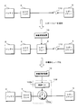
図7は、変形例2に係る半導体ヒューズ109を説明するための模式図であり、車両1のバッテリ2からACCリレー4を経てシガーソケット5へ至るまでの電力供給経路を抜き出して図示してある。図7上段には、従来車両の構成を図示してある。従来車両では、ACCリレー4及びシガーソケット5の間の電力供給経路中にヒューズ110が設けられていた。ヒューズ110は、過電流が流れることによって溶断し、電力供給経路を遮断することによって、シガーソケット5に接続された後付デバイス99に過電流が流れることを防止する。
図7中段には、上述の実施の形態に係る車載更新システム1aの構成を図示してある。上述の実施の形態に係る車載更新システム1aでは、従来構成に対してACCリレー4及びヒューズ110の間にシガーリレー9が追加され、シガーリレー9の通電/遮断の切替制御を車載更新装置10が行う。シガーリレー9が通電状態である際に、ヒューズ110を過電流が流れた場合には、ヒューズ110が溶断され、電力供給経路が遮断される。車載更新装置10は、ECU6aの更新処理を行う際に、シガーリレー9を遮断状態へ切り替えることによって、更新処理中にバッテリ2からシガーソケット5に接続された後付デバイス99へ電力が供給されることを防止する。
図7下段には、変形例2に係る車載更新システム1aの構成を図示してある。変形例2に係る車載更新システム1aは、図7中段に示したシステム構成におけるシガーリレー9及びヒューズ110を半導体ヒューズ109に置き換えた構成である。半導体ヒューズ109は、ACCリレー4及びシガーソケット5の間の電力供給経路中に配されるMOSFET109aと、このMOSFET109aの通電/遮断の切替制御を行う制御IC109bとを有して構成されている。制御IC109bは、MOSFET109aを流れる電流を検知し、例えば検知した電流量が閾値を超える場合にMOSFET109aを通電状態から遮断状態へ切り替える。また制御IC109bは、車載更新装置10から与えられる遮断命令に応じて、MOSFET109aを通電状態から遮断状態へ切り替える。よってMOSFET109aは、制御IC109bが過電流を検知した場合及び車載更新装置10が遮断命令を出力した場合に遮断状態となり、これ以外の場合は通電状態となる。
このように、変形例2に係る車載更新システム1aは、半導体ヒューズ109をシガーリレー9として用いる構成である。半導体ヒューズ109は、ACCリレー4からシガーソケット5までの電力供給経路中に設けられるヒューズ110の機能と、シガーリレー9の機能とを兼ね備える回路素子であるため、ヒューズ110を設ける必要がなくなり、車載更新システム1aを構成する回路素子などの部品点数を削減することができる。
1 車両
1a 車載更新システム
2 バッテリ
3 IGリレー(第2のリレー)
4 ACCリレー(第3のリレー)
5 シガーソケット(車載電装品、接続部)
6a,6b ECU(車載機器)
7 表示装置
8 操作装置
9 シガーリレー(第1のリレー)
10 車載更新装置
11 処理部
12 記憶部
12a 更新用プログラム
13 車内通信部
14 制御信号出力部
21 更新処理部
22 切替制御部
99 後付デバイス
109 半導体ヒューズ
109a MOSFET
109b 制御IC
1a 車載更新システム
2 バッテリ
3 IGリレー(第2のリレー)
4 ACCリレー(第3のリレー)
5 シガーソケット(車載電装品、接続部)
6a,6b ECU(車載機器)
7 表示装置
8 操作装置
9 シガーリレー(第1のリレー)
10 車載更新装置
11 処理部
12 記憶部
12a 更新用プログラム
13 車内通信部
14 制御信号出力部
21 更新処理部
22 切替制御部
99 後付デバイス
109 半導体ヒューズ
109a MOSFET
109b 制御IC
Claims (8)
- 車両に搭載されたバッテリからの電力が供給され、記憶部に記憶されたプログラムを実行して動作する車載機器と、
前記バッテリから前記車両に搭載された車載電装品への電力供給経路中に配され、前記電力供給経路の通電/遮断を切り替える第1のリレーと、
前記車載機器の前記記憶部に記憶されたプログラムを更新する処理を行う更新処理部を有する車載更新装置と、
前記更新処理部が更新処理を行う際に前記第1のリレーを遮断状態へ切り替える切替制御部と
を備えることを特徴とする車載更新システム。 - 前記更新処理部は、前記車両のエンジン停止時に更新処理を行うこと
を特徴とする請求項1に記載の車載更新システム。 - 前記バッテリから車載機器までの電力供給経路中に配され、該電力供給経路の通電/遮断を切り替える第2のリレーと、
前記バッテリから前記第1のリレーまでの電力供給経路中に配され、該電力供給経路の通電/遮断を切り替える第3のリレーと
を備え、
前記切替制御部は、前記更新処理部が更新を行う際に前記第2のリレー及び前記第3のリレーを通電状態へ切り替えること
を特徴とする請求項1又は請求項2に記載の車載更新システム。 - 前記第1のリレーを、半導体ヒューズを用いて構成してあること
を特徴とする請求項1乃至請求項3のいずれか1つに記載の車載更新システム。 - 前記車載電装品は、着脱可能に給電線を接続可能な接続部であること
を特徴とする請求項1乃至請求項4のいずれか1つに記載の車載更新システム。 - 前記接続部はシガーソケットであること
を特徴とする請求項5に記載の車載更新システム。 - 前記車載更新装置が、前記切替制御部を有すること
を特徴とする請求項1乃至請求項6のいずれか1つに記載の車載更新システム。 - 車両に搭載されたバッテリからの電力が供給されて動作する車載機器の記憶部に記憶されたプログラムを更新する処理を行う更新処理部と、
前記バッテリから前記車両に搭載された車載電装品への電力供給経路中に配された第1のリレーを、前記更新処理部が更新処理を行う際に遮断状態へ切り替える切替制御部と
を備えることを特徴とする車載更新装置。
Priority Applications (3)
| Application Number | Priority Date | Filing Date | Title |
|---|---|---|---|
| DE112017005500.8T DE112017005500T5 (de) | 2016-10-31 | 2017-10-27 | Bordeigenes Aktualisierungssystem und bordeigene Aktualisierungsvorrichtung |
| CN201780062347.0A CN109844720A (zh) | 2016-10-31 | 2017-10-27 | 车载更新系统及车载更新装置 |
| US16/344,898 US20190294431A1 (en) | 2016-10-31 | 2017-10-27 | On-board update system and on-board update device |
Applications Claiming Priority (2)
| Application Number | Priority Date | Filing Date | Title |
|---|---|---|---|
| JP2016213359A JP6690500B2 (ja) | 2016-10-31 | 2016-10-31 | 車載更新システム及び車載更新装置 |
| JP2016-213359 | 2016-10-31 |
Publications (1)
| Publication Number | Publication Date |
|---|---|
| WO2018079697A1 true WO2018079697A1 (ja) | 2018-05-03 |
Family
ID=62023712
Family Applications (1)
| Application Number | Title | Priority Date | Filing Date |
|---|---|---|---|
| PCT/JP2017/038836 Ceased WO2018079697A1 (ja) | 2016-10-31 | 2017-10-27 | 車載更新システム及び車載更新装置 |
Country Status (5)
| Country | Link |
|---|---|
| US (1) | US20190294431A1 (ja) |
| JP (1) | JP6690500B2 (ja) |
| CN (1) | CN109844720A (ja) |
| DE (1) | DE112017005500T5 (ja) |
| WO (1) | WO2018079697A1 (ja) |
Families Citing this family (10)
| Publication number | Priority date | Publication date | Assignee | Title |
|---|---|---|---|---|
| JP6665728B2 (ja) * | 2016-08-05 | 2020-03-13 | 株式会社オートネットワーク技術研究所 | 車載更新装置、車載更新システム及び通信装置の更新方法 |
| JP7105604B2 (ja) * | 2018-05-11 | 2022-07-25 | ヤマハ発動機株式会社 | 船外機 |
| JP6742381B2 (ja) * | 2018-10-15 | 2020-08-19 | 本田技研工業株式会社 | 車両制御装置、車両制御方法、およびプログラム |
| JP7192415B2 (ja) * | 2018-11-06 | 2022-12-20 | 株式会社オートネットワーク技術研究所 | プログラム更新システム及び更新処理プログラム |
| JP7526066B2 (ja) * | 2020-09-28 | 2024-07-31 | 株式会社Subaru | 車両 |
| JP7437280B2 (ja) * | 2020-09-28 | 2024-02-22 | 株式会社Subaru | 車両 |
| KR20220132864A (ko) * | 2021-03-24 | 2022-10-04 | 현대자동차주식회사 | 차량 및 차량 제어 방법 |
| WO2023095535A1 (ja) * | 2021-11-26 | 2023-06-01 | 株式会社オートネットワーク技術研究所 | 遮断装置 |
| JP7579309B2 (ja) * | 2022-09-28 | 2024-11-07 | 本田技研工業株式会社 | 制御装置、及び、制御方法 |
| CN119853262A (zh) * | 2025-03-18 | 2025-04-18 | 深圳市立顺电通科技有限公司 | 一种双电源自动切换保护电路 |
Citations (5)
| Publication number | Priority date | Publication date | Assignee | Title |
|---|---|---|---|---|
| JP2013151817A (ja) * | 2012-01-25 | 2013-08-08 | Toyota Motor Corp | 電力制御システム |
| JP2013151222A (ja) * | 2012-01-25 | 2013-08-08 | Toyota Motor Corp | 充電通信装置、充電通信方法、プログラム、媒体 |
| JP2014024444A (ja) * | 2012-07-26 | 2014-02-06 | Nippon Seiki Co Ltd | 電力供給制御装置、計器装置 |
| JP2016060388A (ja) * | 2014-09-18 | 2016-04-25 | 株式会社オートネットワーク技術研究所 | プログラム送信システム及びプログラム送信装置 |
| JP2016170740A (ja) * | 2015-03-16 | 2016-09-23 | 日立オートモティブシステムズ株式会社 | ソフト更新装置、ソフト更新方法 |
Family Cites Families (6)
| Publication number | Priority date | Publication date | Assignee | Title |
|---|---|---|---|---|
| JP3373664B2 (ja) * | 1994-08-05 | 2003-02-04 | マツダ株式会社 | 車両用電源供給装置 |
| JP4242405B2 (ja) * | 2006-09-15 | 2009-03-25 | 三菱電機株式会社 | 車載電子制御装置 |
| JP5013833B2 (ja) * | 2006-12-05 | 2012-08-29 | 株式会社日立製作所 | 家庭電池制御装置、家庭電池制御システム、車載電池制御システム、家庭電池制御方法及び車載電池制御方法 |
| JP2011070287A (ja) | 2009-09-24 | 2011-04-07 | Toyota Motor Corp | プログラム更新装置、センタ及びプログラム更新システム |
| WO2016161042A1 (en) * | 2015-03-30 | 2016-10-06 | Parallel Wireless, Inc. | Power management for vehicle-mounted base station |
| JP2018095066A (ja) * | 2016-12-13 | 2018-06-21 | 株式会社オートネットワーク技術研究所 | 車載電力供給システム、リレーボックス及びリレー制御装置 |
-
2016
- 2016-10-31 JP JP2016213359A patent/JP6690500B2/ja not_active Expired - Fee Related
-
2017
- 2017-10-27 US US16/344,898 patent/US20190294431A1/en not_active Abandoned
- 2017-10-27 CN CN201780062347.0A patent/CN109844720A/zh active Pending
- 2017-10-27 WO PCT/JP2017/038836 patent/WO2018079697A1/ja not_active Ceased
- 2017-10-27 DE DE112017005500.8T patent/DE112017005500T5/de not_active Withdrawn
Patent Citations (5)
| Publication number | Priority date | Publication date | Assignee | Title |
|---|---|---|---|---|
| JP2013151817A (ja) * | 2012-01-25 | 2013-08-08 | Toyota Motor Corp | 電力制御システム |
| JP2013151222A (ja) * | 2012-01-25 | 2013-08-08 | Toyota Motor Corp | 充電通信装置、充電通信方法、プログラム、媒体 |
| JP2014024444A (ja) * | 2012-07-26 | 2014-02-06 | Nippon Seiki Co Ltd | 電力供給制御装置、計器装置 |
| JP2016060388A (ja) * | 2014-09-18 | 2016-04-25 | 株式会社オートネットワーク技術研究所 | プログラム送信システム及びプログラム送信装置 |
| JP2016170740A (ja) * | 2015-03-16 | 2016-09-23 | 日立オートモティブシステムズ株式会社 | ソフト更新装置、ソフト更新方法 |
Also Published As
| Publication number | Publication date |
|---|---|
| JP2018074798A (ja) | 2018-05-10 |
| JP6690500B2 (ja) | 2020-04-28 |
| CN109844720A (zh) | 2019-06-04 |
| DE112017005500T5 (de) | 2019-09-12 |
| US20190294431A1 (en) | 2019-09-26 |
Similar Documents
| Publication | Publication Date | Title |
|---|---|---|
| JP6690500B2 (ja) | 車載更新システム及び車載更新装置 | |
| JP6642393B2 (ja) | 車載更新システム | |
| CN108602474A (zh) | 车载电力供给系统、继电器箱及继电器控制装置 | |
| JP6573500B2 (ja) | ソフトウェア更新システム | |
| JP6897821B2 (ja) | 車両用制御装置 | |
| US9541937B2 (en) | In-vehicle communication system | |
| JP6122412B2 (ja) | 車両用電源ボックス装置 | |
| CN111247038A (zh) | 程序更新装置、程序更新系统及程序更新方法 | |
| JP6116535B2 (ja) | 車両用電源ボックス装置 | |
| CN111051139B (zh) | 控制设备、控制方法和计算机程序 | |
| CN104918829A (zh) | 车载电源控制器 | |
| CN112136106B (zh) | 电子控制装置以及存储介质 | |
| CN111032438B (zh) | 控制设备、控制方法和计算机程序 | |
| US12065092B2 (en) | Vehicle control apparatus and power source supply circuit | |
| JP6840712B2 (ja) | 車載システム | |
| JP2018074799A (ja) | 車載更新システム及び車載更新装置 | |
| JP2018074798A5 (ja) | ||
| WO2024070572A1 (ja) | 車載装置、情報処理方法及び車載システム | |
| JP6401947B2 (ja) | 車両用電装機器接続システム | |
| CN105793115B (zh) | 车辆用电气布线装置 | |
| CN106314329A (zh) | 用于将外部设备与车辆连接的系统和方法 | |
| CN116691345B (zh) | 车辆 | |
| JP2017123106A (ja) | 電子制御装置 | |
| JPH05146079A (ja) | 電源分配装置 | |
| JP2006341794A (ja) | 自動車用電源監視装置 |
Legal Events
| Date | Code | Title | Description |
|---|---|---|---|
| 121 | Ep: the epo has been informed by wipo that ep was designated in this application |
Ref document number: 17865464 Country of ref document: EP Kind code of ref document: A1 |
|
| 122 | Ep: pct application non-entry in european phase |
Ref document number: 17865464 Country of ref document: EP Kind code of ref document: A1 |