WO2018079206A1 - 給油装置 - Google Patents
給油装置 Download PDFInfo
- Publication number
- WO2018079206A1 WO2018079206A1 PCT/JP2017/035893 JP2017035893W WO2018079206A1 WO 2018079206 A1 WO2018079206 A1 WO 2018079206A1 JP 2017035893 W JP2017035893 W JP 2017035893W WO 2018079206 A1 WO2018079206 A1 WO 2018079206A1
- Authority
- WO
- WIPO (PCT)
- Prior art keywords
- fuel
- filler
- diameter
- tube
- port
- Prior art date
- Legal status (The legal status is an assumption and is not a legal conclusion. Google has not performed a legal analysis and makes no representation as to the accuracy of the status listed.)
- Ceased
Links
Images

Classifications
-
- B—PERFORMING OPERATIONS; TRANSPORTING
- B60—VEHICLES IN GENERAL
- B60K—ARRANGEMENT OR MOUNTING OF PROPULSION UNITS OR OF TRANSMISSIONS IN VEHICLES; ARRANGEMENT OR MOUNTING OF PLURAL DIVERSE PRIME-MOVERS IN VEHICLES; AUXILIARY DRIVES FOR VEHICLES; INSTRUMENTATION OR DASHBOARDS FOR VEHICLES; ARRANGEMENTS IN CONNECTION WITH COOLING, AIR INTAKE, GAS EXHAUST OR FUEL SUPPLY OF PROPULSION UNITS IN VEHICLES
- B60K15/00—Arrangement in connection with fuel supply of combustion engines or other fuel consuming energy converters, e.g. fuel cells; Mounting or construction of fuel tanks
- B60K15/03—Fuel tanks
- B60K15/04—Tank inlets
-
- B—PERFORMING OPERATIONS; TRANSPORTING
- B60—VEHICLES IN GENERAL
- B60K—ARRANGEMENT OR MOUNTING OF PROPULSION UNITS OR OF TRANSMISSIONS IN VEHICLES; ARRANGEMENT OR MOUNTING OF PLURAL DIVERSE PRIME-MOVERS IN VEHICLES; AUXILIARY DRIVES FOR VEHICLES; INSTRUMENTATION OR DASHBOARDS FOR VEHICLES; ARRANGEMENTS IN CONNECTION WITH COOLING, AIR INTAKE, GAS EXHAUST OR FUEL SUPPLY OF PROPULSION UNITS IN VEHICLES
- B60K15/00—Arrangement in connection with fuel supply of combustion engines or other fuel consuming energy converters, e.g. fuel cells; Mounting or construction of fuel tanks
- B60K15/03—Fuel tanks
- B60K15/035—Fuel tanks characterised by venting means
-
- F—MECHANICAL ENGINEERING; LIGHTING; HEATING; WEAPONS; BLASTING
- F02—COMBUSTION ENGINES; HOT-GAS OR COMBUSTION-PRODUCT ENGINE PLANTS
- F02M—SUPPLYING COMBUSTION ENGINES IN GENERAL WITH COMBUSTIBLE MIXTURES OR CONSTITUENTS THEREOF
- F02M37/00—Apparatus or systems for feeding liquid fuel from storage containers to carburettors or fuel-injection apparatus; Arrangements for purifying liquid fuel specially adapted for, or arranged on, internal-combustion engines
-
- B—PERFORMING OPERATIONS; TRANSPORTING
- B60—VEHICLES IN GENERAL
- B60K—ARRANGEMENT OR MOUNTING OF PROPULSION UNITS OR OF TRANSMISSIONS IN VEHICLES; ARRANGEMENT OR MOUNTING OF PLURAL DIVERSE PRIME-MOVERS IN VEHICLES; AUXILIARY DRIVES FOR VEHICLES; INSTRUMENTATION OR DASHBOARDS FOR VEHICLES; ARRANGEMENTS IN CONNECTION WITH COOLING, AIR INTAKE, GAS EXHAUST OR FUEL SUPPLY OF PROPULSION UNITS IN VEHICLES
- B60K15/00—Arrangement in connection with fuel supply of combustion engines or other fuel consuming energy converters, e.g. fuel cells; Mounting or construction of fuel tanks
- B60K15/03—Fuel tanks
- B60K2015/03328—Arrangements or special measures related to fuel tanks or fuel handling
- B60K2015/03394—Arrangements or special measures related to fuel tanks or fuel handling for preventing expulsion of fuel during filling of the tank
-
- B—PERFORMING OPERATIONS; TRANSPORTING
- B60—VEHICLES IN GENERAL
- B60K—ARRANGEMENT OR MOUNTING OF PROPULSION UNITS OR OF TRANSMISSIONS IN VEHICLES; ARRANGEMENT OR MOUNTING OF PLURAL DIVERSE PRIME-MOVERS IN VEHICLES; AUXILIARY DRIVES FOR VEHICLES; INSTRUMENTATION OR DASHBOARDS FOR VEHICLES; ARRANGEMENTS IN CONNECTION WITH COOLING, AIR INTAKE, GAS EXHAUST OR FUEL SUPPLY OF PROPULSION UNITS IN VEHICLES
- B60K15/00—Arrangement in connection with fuel supply of combustion engines or other fuel consuming energy converters, e.g. fuel cells; Mounting or construction of fuel tanks
- B60K15/03—Fuel tanks
- B60K15/04—Tank inlets
- B60K2015/0458—Details of the tank inlet
- B60K2015/0464—Details of the tank inlet comprising a flexible or extendable filler pipes, e.g. corrugated, foldable or with bellows
-
- B—PERFORMING OPERATIONS; TRANSPORTING
- B60—VEHICLES IN GENERAL
- B60K—ARRANGEMENT OR MOUNTING OF PROPULSION UNITS OR OF TRANSMISSIONS IN VEHICLES; ARRANGEMENT OR MOUNTING OF PLURAL DIVERSE PRIME-MOVERS IN VEHICLES; AUXILIARY DRIVES FOR VEHICLES; INSTRUMENTATION OR DASHBOARDS FOR VEHICLES; ARRANGEMENTS IN CONNECTION WITH COOLING, AIR INTAKE, GAS EXHAUST OR FUEL SUPPLY OF PROPULSION UNITS IN VEHICLES
- B60K15/00—Arrangement in connection with fuel supply of combustion engines or other fuel consuming energy converters, e.g. fuel cells; Mounting or construction of fuel tanks
- B60K15/03—Fuel tanks
- B60K15/04—Tank inlets
- B60K2015/0458—Details of the tank inlet
- B60K2015/047—Manufacturing of the fuel inlet or connecting elements to fuel inlet, e.g. pipes or venting tubes
-
- B—PERFORMING OPERATIONS; TRANSPORTING
- B60—VEHICLES IN GENERAL
- B60K—ARRANGEMENT OR MOUNTING OF PROPULSION UNITS OR OF TRANSMISSIONS IN VEHICLES; ARRANGEMENT OR MOUNTING OF PLURAL DIVERSE PRIME-MOVERS IN VEHICLES; AUXILIARY DRIVES FOR VEHICLES; INSTRUMENTATION OR DASHBOARDS FOR VEHICLES; ARRANGEMENTS IN CONNECTION WITH COOLING, AIR INTAKE, GAS EXHAUST OR FUEL SUPPLY OF PROPULSION UNITS IN VEHICLES
- B60K15/00—Arrangement in connection with fuel supply of combustion engines or other fuel consuming energy converters, e.g. fuel cells; Mounting or construction of fuel tanks
- B60K15/03—Fuel tanks
- B60K15/04—Tank inlets
- B60K2015/0458—Details of the tank inlet
- B60K2015/048—Arrangements for sealing the fuel inlet during filling
Definitions
- the present invention relates to a fueling device.
- Japanese Patent No. 531444, Japanese Patent Application Laid-Open No. 2003-80959 and Japanese Patent Application Laid-Open No. 2004-351658 disclose a filler tube that is fitted to an outer peripheral surface of an oil supply port into which a nozzle of an oil supply gun is inserted and an outlet of the oil supply port. Is provided.
- the inner diameter of the filler tube is set based on the fuel flow condition from the fuel filler port to the fuel tank. For example, the inner diameter of the filler tube is set so that the flow rate of fuel flowing through the filler tube per unit time is a predetermined amount or more. And the filler tube is formed so that it may become substantially the same as the set internal diameter over the full length.
- the inner diameter on the outlet side of the filler port is formed to be the same as the inner diameter of the filler tube. Therefore, in a state where one end of the filler tube is fitted to the outer peripheral surface on the outlet side of the filler port, the inner diameter is formed to be approximately the same over the entire length from the vicinity of the outlet of the filler port to the other end of the filler tube. ing.
- the inlet side of the fuel filler port has a larger inner diameter than the outlet side of the fuel filler port so that the nozzle of the fuel gun can be easily inserted. Therefore, the oil filler opening is reduced in diameter from the inlet side to the outlet side at the intermediate portion.
- the shape of the filler tube can be designed freely.
- the filler tube has a bent portion at an appropriate position in relation to the peripheral structure.
- the fuel filler port is formed in a straight line in a range from the inlet side to the outlet side. Therefore, the longer the fuel filler port, the more restrictive is the layout of the filler piping composed of the fuel filler port and the filler tube.
- the total length of the oil filler port becomes long.
- it is required to shorten the total length of the fuel filler port.
- An object of the present invention is to provide an oil supply device capable of shortening the total length of the oil supply port and improving the degree of freedom of the layout of the filler piping.
- the fueling device is formed in a cylindrical shape, a fueling port into which a nozzle of a fueling gun is inserted from the inlet side, one end connected to the outlet side of the fueling port, and the other end to the fuel tank side And a filler tube to be connected.
- the filler tube is formed with a fitting cylinder part fitted to the outer surface on the outlet side of the filler opening, the fitting cylinder part side having a large diameter, and a side opposite to the fitting cylinder part having a small diameter.
- a tapered cylindrical portion connected to a small diameter side of the tapered cylindrical portion, formed to have a smaller diameter than the fitting cylindrical portion, and formed to a predetermined inner diameter set based on a fuel flow condition from the fuel filler port to the fuel tank.
- a small-diameter cylindrical portion is formed larger than the predetermined inner diameter of the small-diameter cylindrical portion of the filler tube.
- the filler tube includes the tapered tube portion between the fitting tube portion and the small diameter tube portion. That is, the oil supply apparatus according to the present invention corresponds to a structure in which the reduced diameter portion provided in the conventional oil supply port is shifted to the filler tube side. Therefore, the total length of the fuel filler opening can be shortened. And even if the central axis is linear from the end of the filler tube to the tapered cylinder, the small-diameter cylindrical part of the filler tube can also bend the central axis in the vicinity of the portion connected to the tapered cylinder. In addition, the central axis can be linear.
- the small-diameter cylindrical portion of the filler tube can have a free shape over the entire length. That is, the portion corresponding to the small diameter portion of the fuel filler opening in the conventional structure can be bent. As a result, the layout flexibility of the filler piping of the fueling device is improved.
- FIG. 3 is an axial sectional view of the fueling device 1 during fueling in the fueling device 1 shown in FIG. 2. It is an axial sectional view of oil supply device 100 in a third embodiment. In oil supply apparatus 100 shown in FIG. 4, it is an axial sectional view of oil supply apparatus 100 at the time of oil supply.
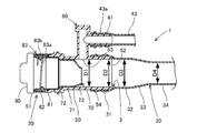
- the structure of the oil supply apparatus 1 is demonstrated with reference to FIG.
- the fueling device 1 is a fuel line from a fueling port 20 to an internal combustion engine (not shown) in an automobile.
- the fuel tank 20 to the fuel tank 10 which are a part of the fueling apparatus 1 will be described.
- the fueling device 1 includes at least a fuel tank 10, a fueling port 20, a filler tube 30, and a breather line 40.
- the fuel tank 10 stores liquid fuel such as gasoline.
- the liquid fuel stored in the fuel tank 10 is supplied to an internal combustion engine (not shown) and used to drive the internal combustion engine.
- the fuel filler port 20 is provided near the outer surface of the automobile into which the nozzle 2a of the fuel gun 2 can be inserted.
- the fuel filler opening 20 may be a type provided with an oil filler cap 90 (shown in FIG. 2), or may be a type not provided with an oil filler cap.
- the type of fuel filler opening 20 provided with the fuel filler cap 90 is given as an example.
- the fuel filler port 20 mainly includes an inlet and an outlet, and a fuel filler body 50 having a central axis formed in a straight line, a breather cylinder portion 60 connected to the outer peripheral surface of the fuel filler body 50, and a fuel cap 90. With.
- the filler tube 30 connects the fuel filler main body 50 of the fuel filler 20 and the fuel tank 10. That is, one end of the filler tube 30 is directly connected to the outlet side of the fuel filler opening 20. The other end of the filler tube 30 is connected to the fuel tank 10 side. When the other end of the filler tube 30 is directly connected to the fuel tank 10, it may be connected to a connector (not shown) that relays to the fuel tank 10.
- the nozzle 2a of the fuel gun 2 is inserted into the fuel filler port 20 and liquid fuel is supplied from the nozzle 2a of the fuel gun 2 so that the liquid fuel passes through the filler tube 30 and is stored in the fuel tank 10. .
- the liquid fuel when the liquid fuel is full in the fuel tank 10, the liquid fuel is stored in the filler tube 30, and the liquid fuel comes into contact with the tip of the nozzle 2 a of the fuel gun 2, whereby the liquid fuel by the nozzle 2 a of the fuel gun 2. Is automatically stopped (auto-stop function). Specifically, a pilot hole 2b (shown in FIG. 3) for detecting liquid fuel is formed on the lower surface of the nozzle 2a on the front end side. Then, when the pilot hole 2b is blocked with the liquid fuel, the fuel supply gun 2 stops the supply of the liquid fuel.
- a pilot hole 2b shown in FIG. 3
- the breather line 40 connects the fuel tank 10 and the breather cylinder 60 of the fuel filler opening 20.
- the breather line 40 is a line for circulating fuel vapor or air in the fuel tank 10 from the fuel tank 10 side to the fuel filler port 20 when liquid fuel is supplied to the fuel tank 10 via the filler tube 30. .
- the breather line 40 includes a cut valve device 41, a connector 42, and a breather tube 43.
- the cut valve device 41 is disposed at the upper part of the fuel tank 10 and, when opened, the fuel vapor or air in the fuel tank 10 is discharged to the fuel filler opening 20 side.
- the cut valve device 41 includes a metal connection pipe.
- the connector 42 is connected to the connection pipe of the cut valve device 41.
- the connector 42 is, for example, a connector described in Japanese Patent No. 3775656 or a configuration obtained by removing the flow control valve from the connector. That is, the connector 42 is detachably provided from the connection pipe of the cut valve device 41.
- the breather tube 43 is a long tube (hose) formed of resin, and connects the connector 42 and the breather tube portion 60 of the fuel filler opening 20.
- the liquid fuel returns from the fuel tank 10 to the fuel supply port 20 via the breather tube 43.
- the breather tube 43 circulates the fuel vapor during refueling and the recirculated fuel during auto-stop.
- the oil filler 20 includes a resin filler body 50, a resin breather cylinder 60, a resin nozzle guide 70, a rubber seal member 81, a seal pressing member 82, a metal mouthpiece 83, and an oil filler.
- a cap 90 is provided.
- the fuel filler body 50 is made of resin and is formed in a cylindrical shape. Specifically, the fuel filler main body 50 is formed so that the central axis is linear, and has openings at both ends.
- the inlet 51 side (left side in FIG. 2) of the fuel filler body 50 is located on the outer surface side of the automobile, and the outlet 52 side (right side in FIG. 2) of the fuel filler body 50 is located on the fuel tank 10 side.
- a nozzle 2 a (shown in FIGS. 1 and 3) of the fuel gun 2 is inserted into the inlet 51 of the fuel filler main body 50.
- An outlet 52 of the fuel filler main body 50 (corresponding to the outlet of the fuel filler 20) supplies fuel to the filler tube 30 (shown in FIG. 1).
- the fuel filler main body 50 is provided with a reflux port 53 on the upper side or the side near the center in the axial direction on the circumferential surface.
- the inner peripheral surface of the fuel filler main body 50 is formed in a two-step staircase shape from the inlet 51 to the reflux port 53 in the range from the inlet 51 to the part of the reflux port 53.
- the inner peripheral surface of the fuel filler main body 50 is formed to have the same diameter over a range from the portion of the reflux port 53 to the outlet 52. That is, the inlet 51 is formed with the largest diameter in the fuel filler main body 50.
- a tube locking portion 54 is formed on the outer peripheral surface of the fuel filler main body 50 on the outlet 52 side from the reflux port 53.
- the tube locking portion 54 is formed in a bamboo shoot shape, that is, in a plurality of irregularities in the axial direction.
- the tube locking portion 54 is fitted with the fitting cylinder portion 31 located at the end of the filler tube 30. Therefore, the tube locking portion 54 suppresses the filler tube 30 from coming off from the fuel filler main body 50.
- an O-ring (not shown) is fitted in the recess of the tube locking portion 54. That is, the O-ring seals between the tube locking portion 54 and the filler tube 30.
- the inner diameter of the portion of the recirculation port 53 of the fuel filler main body 50 is D1.
- the inner diameter of the outlet 52 of the fuel filler main body 50 is formed at D2.
- the inner peripheral surface of the fuel filler main body 50 is formed to have the same diameter over a range from the portion of the reflux port 53 to the outlet 52. Therefore, the inner diameter D1 of the portion of the reflux port 53 and the inner diameter D2 of the outlet 52 are the same diameter.
- the range from the part of the reflux port 53 to the outlet 52 includes a part where the tube locking part 54 is formed.
- the inner diameter of the portion where the tube locking portion 54 is formed is formed to be the same as the inner diameter D1 of the portion of the reflux port 53 and the inner diameter D2 of the outlet 52. . Further, the inner diameter D1 of the portion of the reflux port 53 and the inner diameter D2 of the outlet 52 of the fuel filler main body 50 are formed sufficiently larger than a small-diameter opening of a tapered portion 73 of the nozzle guide 70 described later.
- the breather cylinder portion 60 is formed in an L-shaped cylinder shape from resin.
- the breather cylinder portion 60 is integrally formed outside the peripheral surface of the fuel filler main body 50.
- One of the L-shaped breather cylinder portions 60 is connected to the reflux port 53 of the fuel filler main body 50.
- one of the L-shaped breather cylinder portions 60 is formed to extend outward from the outer peripheral surface of the fuel filler body 50.
- one of the L-shaped breather cylinder portions 60 may extend in a direction perpendicular to the central axis of the fuel filler main body 50, or may extend in an inclined direction.
- the other L-shaped part of the breather cylinder part 60 is formed so as to be substantially parallel to the fuel filler body 50.
- the other L-shaped port of the breather cylinder 60 opens in the same direction as the outlet 52 of the fuel filler main body 50.
- a tube locking portion 61 is formed on the other L-shaped outer peripheral surface of the breather cylinder portion 60.
- the tube locking portion 61 is formed in a bamboo shoot shape, that is, in a plurality of irregularities in the axial direction.
- An end portion 43 a of a resin breather tube 43 is fitted into the tube locking portion 61. At this time, the end portion 43a of the breather tube 43 is locked to the tube locking portion 61 in the expanded state.
- the tube locking portion 61 prevents the breather tube 43 from coming off from the breather tube portion 60.
- An O-ring (not shown) is fitted in the recess of the tube locking portion 61. That is, the O-ring seals between the tube locking portion 61 and the breather tube 43.
- the nozzle guide 70 is formed in a cylindrical shape from resin and guides the nozzle 2a (shown in FIG. 1) of the fuel gun 2 inserted into the fuel filler main body 50.
- the nozzle guide 70 is inserted in the fuel filler main body 50.
- the nozzle guide 70 is inserted from the inlet 51 side of the fuel filler main body 50 and is disposed closer to the inlet 51 than the reflux port 53.
- the nozzle guide 70 includes a large diameter portion 71, a flange portion 72, and a tapered portion 73.
- the large-diameter portion 71 is formed in a substantially cylindrical shape and substantially coincides with the inner diameter in the vicinity of the reflux port 53 of the fuel filler main body 50.
- the flange portion 72 is formed to extend radially outward from the end of the opening of the large diameter portion 71.
- the flange portion 72 is abutted against a step portion on the inner peripheral surface of the fuel filler main body 50.
- the flange portion 72 and the fuel filler main body 50 are provided with uneven portions (not shown) that are locked in the circumferential direction. That is, the flange portion 72 is positioned with a predetermined phase with respect to the fuel filler main body 50.
- the tapered portion 73 is formed so as to reduce the diameter from the large diameter portion 71 to the outlet 52 side of the fuel filler main body 50.
- the small diameter opening of the tapered portion 73 is located in the vicinity of the reflux port 53. Further, the small-diameter opening of the tapered portion 73 is eccentric in a direction away from the reflux port 53 with respect to the large-diameter portion 71. That is, the small-diameter opening of the tapered portion 73 is located far from the recirculation port 53, but is located near the surface opposite to the recirculation port 53 on the inner peripheral surface of the fuel filler main body 50. Accordingly, the outer peripheral surface of the tapered portion 73 has a function of guiding the liquid fuel discharged from the reflux port 53 to the outlet 52 side.
- the small-diameter opening of the tapered portion 73 has an inner diameter that is slightly larger than the nozzle 2 a of the fuel gun 2. That is, the taper portion 73 has a function of guiding the nozzle 2a of the fuel supply gun 2 from the large diameter portion 71 toward the small diameter opening of the taper portion 73, and is in a stable state with the nozzle 2a of the fuel supply gun 2 inserted. It has a function to hold in.
- the seal member 81 is an annular member such as an O-ring, for example.
- the seal member 81 is fitted on the inner peripheral surface of the fuel filler body 50 on the inlet 51 side.
- the seal member 81 is in contact with the stepped end surface of the inlet 51 most in the fuel filler main body 50.
- the seal pressing member 82 is disposed on the inlet 51 side of the fuel filler main body 50, and is disposed on the inlet 51 side from the seal member 81. That is, the seal member 81 is positioned by the seal pressing member 82 and the flange portion 72 of the nozzle guide 70 sandwiching the seal member 81 in the axial direction.
- the mouth metal fitting 83 is formed in a cylindrical shape and attached to the inlet 51 of the fuel filler main body 50. That is, the opening of the base metal fitting 83 corresponds to the inlet of the fuel filler opening 20.
- the base metal fitting 83 has a function of preventing the nozzle 2a of the fuel gun 2 from coming into direct contact with the resin fuel filler main body 50.
- the base metal fitting 83 includes an inner peripheral portion 83a and an outer peripheral portion 83b that are integrally formed.
- the inner peripheral portion 83 a of the base metal fitting 83 is positioned on the inner peripheral side of the portion on the inlet 51 side of the fuel filler main body 50 and further positioned on the inner peripheral side of the seal pressing member 82.
- the inner peripheral portion 83 a of the base metal fitting 83 contacts the flange portion 72 of the nozzle guide 70 to position the nozzle guide 70.
- the inner peripheral portion 83 a of the mouthpiece metal 83 is in contact with the seal member 81, thereby preventing fuel from leaking from between the mouthpiece metal 83 and the fuel filler body 50. Further, an internal thread that is screwed into the oil supply cap 90 is formed on the inner peripheral portion 83 a of the mouthpiece 83.
- the outer peripheral portion 83 b of the base metal fitting 83 is located on the outer peripheral side of the portion on the inlet 51 side of the fuel filler main body 50.
- a male screw is formed on the outer peripheral surface of the oiling cap 90 and is screwed into the female screw of the mouthpiece 83.
- the oil filler cap 90 closes the opening of the base metal fitting 83, that is, the inlet of the oil filler port 20.
- the filler tube 30 is made of resin and connects the fuel filler body 50 and the fuel tank 10. The portion connected to the filler port body 50 of the filler tube 30 will be described in detail.
- the filler tube 30 includes a fitting cylinder part 31, a large diameter straight cylinder part 32, a tapered cylinder part 33, and a small diameter cylinder part 34.
- the fitting cylinder part 31 is located at the end of the filler tube 30.
- the fitting cylinder portion 31 is fitted to a tube locking portion 54 formed on the outer peripheral surface on the outlet 52 side of the fuel filler main body 50.
- the fitting cylinder portion 31 has an inner diameter slightly smaller than the outer diameter of the tube locking portion 54 before being fitted to the tube locking portion 54. Accordingly, the fitting cylinder portion 31 is in a state of being expanded in diameter by being fitted to the tube locking portion 54, and prevents the filler tube 30 from coming out of the fuel filler main body 50.
- the large diameter straight tube portion 32 is continuously connected to the fitting tube portion 31.
- the large-diameter straight tube portion 32 is formed in a straight shape (straight tube), that is, a central axis is formed in a straight line, and is formed in the same diameter over the entire axial length.
- the large diameter straight cylinder part 32 is formed in the same shape as the fitting cylinder part 31 in a state before the fitting cylinder part 31 is fitted to the tube locking part 54. That is, the large-diameter straight tube portion 32 functions as a fitting length adjustment portion by the fitting tube portion 31.
- the inner diameter of the large-diameter straight tube portion 32 is D3.
- the inner diameter D3 of the large-diameter straight tube portion 32 is approximately the same as the inner diameter D2 of the outlet 52 of the fuel filler main body 50.
- the inner diameter D3 of the large-diameter straight tube portion 32 may be the same as the inner diameter D2 of the outlet 52, may be slightly larger than the inner diameter D2, or may be slightly smaller than the inner diameter D2.
- the inner diameter of the large-diameter straight tube portion 32 is such that the fitting tube portion 31 can be fitted to the oil filler main body 50, and the locking force of the fitting tube portion 31 to the tube locking portion 54 is a predetermined value or more. It is set to become.
- the tapered tube portion 33 is continuously connected to the large diameter straight tube portion 32.
- the taper cylinder part 33 has a central axis formed in a straight line.
- the large diameter straight tube portion 32 side of the tapered tube portion 33 is formed to have a large diameter, and the opposite side of the taper tube portion 33 from the large diameter straight tube portion 32 is formed to have a small diameter. That is, the inner diameter on the large diameter side of the tapered cylinder portion 33 is the same as the inner diameter D3 of the large diameter straight cylinder portion 32.
- the tapered tube portion 33 is formed coaxially with the fitting tube portion 31 and the large diameter straight tube portion 32.
- the tapered cylindrical portion 33 has a function corresponding to a tapered portion in a conventional oil filler (a member corresponding to the oil filler 20 of the present embodiment). That is, the taper cylinder portion 33 serves as a connecting portion for improving the flow of the liquid fuel from the fuel filler opening 20 to the small diameter cylinder portion 34.
- the small diameter cylindrical portion 34 is a portion that occupies most of the center in the axial direction of the filler tube 30. That is, the small diameter cylindrical portion 34 is located in a large part between the fuel filler opening 20 and the fuel tank 10.
- the small diameter cylindrical portion 34 is continuously connected to the small diameter side of the tapered cylindrical portion 33. That is, the small diameter cylindrical portion 34 is formed to have a smaller diameter than the fitting cylindrical portion 31 and the large diameter straight cylindrical portion 32.
- the inner diameter of the small diameter cylindrical portion 34 is D4. That is, the inner diameter D4 of the small diameter cylindrical portion 34 is smaller than the inner diameter D2 of the outlet 52 of the fuel filler main body 50 and smaller than the inner diameter D3 of the large diameter straight cylindrical portion 32.
- An inner diameter D4 of the small-diameter cylindrical portion 34 is formed to a predetermined inner diameter that is set based on a fuel flow condition from the fuel filler port 20 to the fuel tank 10. For example, the inner diameter D4 of the small diameter cylindrical portion 34 is set so that the flow rate per unit time of the liquid fuel flowing through the small diameter cylindrical portion 34 is a predetermined amount or more.
- the central axis of the small-diameter cylindrical portion 34 may be linear or bent.
- the shape of the central axis of the small diameter cylindrical portion 34 is freely designed according to the positions of the fuel filler opening 20 and the fuel tank 10.
- the central axis of the small-diameter cylindrical portion 34 may be formed so as to be bent immediately from the connecting portion with the small-diameter side of the tapered cylindrical portion 33, or at an arbitrary distance so as to extend coaxially with the tapered cylindrical portion 33. You may form linearly.
- the inner peripheral surface of the fuel filler main body 50 is formed with the same diameter (D1, D2) between the portion of the reflux port 53 and the outlet 52, the liquid fuel flows smoothly. Further, since the inner peripheral surface smoothly changes in the range from the large diameter straight cylindrical portion 32 of the filler tube 30 to the small diameter cylindrical portion 34 via the tapered cylindrical portion 33, the liquid fuel flows smoothly. .
- the groove portion 3 discontinuously connects the inner peripheral surface near the outlet 52 of the fuel filler body 50 and the inner peripheral surface of the filler tube 30. Therefore, the groove part 3 becomes a cause of obstructing the flow of the liquid fuel. For example, the groove part 3 causes a vortex or a backflow.
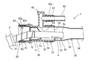
- the fueling apparatus 1 at the time of fueling is demonstrated with reference to FIG.
- the fueling cap 90 is removed and the inlet of the fueling port 20 is opened.
- the nozzle 2 a of the fueling gun 2 is inserted into the inlet of the fueling port 20.
- the nozzle 2 a of the fuel gun 2 contacts the tapered portion 73 of the nozzle guide 70 and passes through the small diameter opening of the tapered portion 73 of the nozzle guide 70.
- the nozzle 2 a of the fueling gun 2 is inserted all the way into the fully inserted state.
- the tip of the nozzle 2 a When the refueling gun 2 is fully inserted, the tip of the nozzle 2 a is positioned in the axial range of the large-diameter straight cylindrical portion 32 and the tapered cylindrical portion 33 of the filler tube 30. That is, the groove part 3 is located in the inlet side of the fuel filler opening 20 from the front-end
- the liquid fuel When the liquid fuel is discharged from the nozzle 2a of the fueling gun 2, the liquid fuel travels from the opening of the nozzle 2a to the small diameter cylindrical portion 34 of the filler tube 30. At this time, the liquid fuel spreads from the opening of the nozzle 2a. A part of the liquid fuel hits the tapered cylinder portion 33. However, the liquid fuel that has hit the tapered cylindrical portion 33 travels along the tapered cylindrical portion 33 toward the small diameter cylindrical portion 34. Since the groove portion 3 is located on the inlet side of the fuel filler opening 20 from the tip of the nozzle 2a, the liquid fuel discharged from the nozzle 2a does not directly hit the groove portion 3.
- the nozzle 2a of the fuel gun 2 is provided with a pilot hole 2b for auto-stop detection on the lower surface on the tip side. That is, the pilot hole 2b is formed at a position spaced from the tip of the nozzle 2a.
- the pilot hole 2 b is located in the axial range of the large diameter straight cylindrical portion 32 and the tapered cylindrical portion 33 of the filler tube 30. That is, the groove part 3 is located in the inlet side of the fuel filler opening 20 from the pilot hole 2b at the time of full insertion.
- the fuel supply gun 2 When the fuel tank 10 is full and liquid fuel is filled at the position of the pilot hole 2b, the air flow in the pilot hole 2b is blocked. Then, the fuel supply gun 2 operates the auto stop function and stops the supply of the liquid fuel.
- the auto-stop function operates even when the liquid fuel discharged from the nozzle 2a rebounds and enters the pilot hole 2b.
- the auto stop function does not operate due to the rebound of the liquid fuel.
- the filler tube 30 includes a large-diameter straight tube portion 32 between the fitting tube portion 31 and the taper tube portion 33. Accordingly, the groove portion 3 is formed between the end surface on the outlet side of the fuel filler port 20 and the large-diameter straight tube portion 32.
- the flow direction of the bounced liquid fuel becomes smooth at the large-diameter straight cylinder 32 before reaching the groove 3. . Even with the presence of the large-diameter straight tube portion 32, the liquid fuel hardly rebounds toward the pilot hole 2b.
- the liquid fuel flows from the reflux port 53 into the fuel filler main body 50 through the breather tube 43.
- the liquid fuel that has recirculated flows from the recirculation port 53 to the outlet of the fuel filler 20 (the outlet 52 of the fuel filler main body 50).
- the amount of liquid fuel that has recirculated is less than that of liquid fuel discharged from the nozzle 2a. Therefore, the amount of liquid fuel that has flowed back toward the pilot hole 2b is very small.
- the liquid fuel that has flowed back may be dispersed by the grooves 3.
- the groove 3 is separated from the pilot hole 2b. Therefore, most of the liquid fuel dispersed by the groove 3 does not go to the pilot hole 2b. Therefore, the auto stop function does not operate by the liquid fuel that has been refluxed.
- the fuel filler opening 20 is formed in a substantially cylindrical shape.
- the filler tube 30 includes a tapered cylindrical portion 33 that guides the flow of liquid fuel to the small diameter cylindrical portion 34. That is, the inner diameter D ⁇ b> 2 of the outlet of the fuel filler 20 (the outlet 52 of the filler main body 50) is formed larger than the inner diameter D ⁇ b> 4 of the small-diameter cylindrical portion 34 of the filler tube 30.
- the oil supply device 1 corresponds to a structure in which a reduced diameter portion provided in a conventional oil supply port is shifted to the filler tube 30 side.
- the inner peripheral surface of the fuel filler port 20 is formed to have the same diameter (D1, D2) over a range from the portion of the reflux port 53 to the outlet 52. That is, the inner diameter D1 of the part of the reflux port 53 is equal to the inner diameter D2 of the outlet 52, and is also equal to the inner diameter of the part where the fitting cylinder part 31 is fitted.
- the tube locking portion 54 needs to have a length that can secure the locking force with the fitting tube portion 31 of the filler tube 30. Accordingly, the length from the reflux port 53 to the outlet 52 in the fuel filler main body 50 depends on the length of the tube locking portion 54. In other words, the length from the reflux port 53 to the outlet 52 can be set to the shortest length that can secure the locking force with the fitting cylinder part 31.
- the total length of the fuel filler 20 can be shortened. As shown in FIG. 3, the nozzle 2 a of the fueling gun 2 at the time of full insertion protrudes from the outlet of the fueling port 20. The total length of the fuel filler 20 is so short.
- the fitting tube portion 31, the large-diameter straight tube portion 32, and the taper tube portion 33 of the filler tube 30 are formed so that the central axis is linear. That is, the portion from the fuel filler opening 20 to the tapered cylindrical portion 33 of the filler tube 30 is formed in a straight line.
- the small diameter tube portion 34 of the filler tube 30 is centered near the portion connected to the taper tube portion 33.
- the axis can be bent or the central axis can be linear. That is, the small-diameter cylindrical portion 34 of the filler tube 30 can have a free shape over the entire length. That is, the portion corresponding to the small diameter portion of the fuel filler opening in the conventional structure can be bent. As a result, the layout flexibility of the filler piping (20, 30) of the fueling device 1 is improved.
- the filler tube 30 includes a large-diameter straight tube portion 32 between the fitting tube portion 31 and the taper tube portion 33.
- the filler tube 30 does not include the large-diameter straight tube portion 32. That is, in the filler tube 30 in the second embodiment, the large diameter side of the fitting tube portion 31 and the taper tube portion 33 is directly connected.
- the length from the inlet of the fuel filler port 20 to the tapered cylindrical portion 33 of the filler tube 30 is shortened.
- the small diameter cylinder part 34 can be made into a free shape, the layout freedom degree of filler piping (20, 30) further improves.
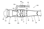
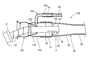
- the oil supply apparatus 100 of 3rd embodiment is demonstrated with reference to FIG. 4 and FIG.
- the fueling device 100 includes at least a fuel tank 10, a fueling port 120, a filler tube 30, and a breather line 40.
- the fuel filler 120 includes a metal filler main body 150, a metal breather cylinder 160, a metal nozzle guide 170, and a fuel cap 90.
- the portions corresponding to the fuel filler main body 50 and the base metal fitting 83 in the first embodiment are made of an integral member made of metal.
- the inner diameter D1 of the portion of the reflux port 153 and the inner diameter D11 of the portion to which the fitting tube portion 31 of the filler tube 30 is fitted are formed to have the same diameter.
- a guide portion for facilitating insertion of the end portion of the filler tube 30, a protrusion for locking the fitting tube portion 31, and a portion for fitting the fitting tube portion 31, and A cylindrical portion for securing the fitting length is included.
- the inner diameter D11 of the portion into which the fitting cylinder portion 31 is fitted corresponds to the inner diameter of the cylindrical portion.
- the inner diameter D2 of the outlet 152 of the fuel filler main body 150 is smaller than the inner diameters D1 and D11 in order to secure a guiding portion.
- the inner diameter D ⁇ b> 2 of the outlet 152 is larger than the inner diameter D ⁇ b> 3 of the large-diameter straight tube portion 32 of the filler tube 30 and the inner diameter D ⁇ b> 4 of the small-diameter tube portion 34.
- the breather cylinder portion 160 is formed in an L shape and is integrally joined to the fuel filler main body 150. Further, the nozzle guide 170 is integrally joined to the inside of the fuel filler main body 150.
- various joining methods such as welding, welding, such as brazing, are applicable as the joining method with respect to the oil filler main body 150, for example.
- the fueling device 100 of the third embodiment also has the same effect as the fueling device 1 of the first embodiment. That is, the length from the inlet 151 of the fuel filler opening 120 to the tapered cylindrical portion 33 of the filler tube 30 is shortened. Therefore, since the small diameter cylinder part 34 can be made into a free shape, the layout freedom degree of filler piping (120, 30) further improves.
- the filler port body 150 is made of metal, the thickness of the filler port body 150 can be made thinner than that of the resin. Therefore, the depth of the groove 3 formed between the end surface of the outlet 152 of the fuel filler main body 150 and the inner peripheral surface of the filler tube 30 is shallow. For this reason, compared with the first embodiment, the influence of the groove 3 is further reduced. That is, the operation of the auto-stop function is further suppressed when the liquid fuel rebounds at the groove 3.
Landscapes
- Engineering & Computer Science (AREA)
- Chemical & Material Sciences (AREA)
- Combustion & Propulsion (AREA)
- Mechanical Engineering (AREA)
- Life Sciences & Earth Sciences (AREA)
- Sustainable Development (AREA)
- Sustainable Energy (AREA)
- Transportation (AREA)
- General Engineering & Computer Science (AREA)
- Cooling, Air Intake And Gas Exhaust, And Fuel Tank Arrangements In Propulsion Units (AREA)
Abstract
給油口の全長を短くすると共に、フィラー配管のレイアウトの自由度を向上させることができる給油装置を提供する。フィラーチューブ(30)は、給油口(20)の出口(52)側の外周面に嵌合される嵌合筒部(31)と、嵌合筒部(31)側が大径に形成され、かつ、嵌合筒部(31)と反対側が小径に形成されるテーパ筒部(33)と、テーパ筒部(33)の小径側に接続され、嵌合筒部(31)より小径に形成され、給油口(20)から燃料タンク(10)への燃料流通条件に基づいて設定された所定内径(D4)に形成される小径筒部(34)とを備える。給油口(20)の出口(52)の内径(D2)は、フィラーチューブ(30)の小径筒部(34)の所定内径(D4)より大きく形成される。
Description
本発明は、給油装置に関するものである。
特許第5321444号公報、特開2003-80959号公報及び特開2004-351658号公報には、給油ガンのノズルが挿入される給油口と、給油口の出口の外周面に嵌合されるフィラーチューブとを備える給油装置が記載されている。フィラーチューブの内径は、給油口から燃料タンクへの燃料流通条件に基づいて設定されている。例えば、フィラーチューブを流通する燃料の単位時間当たりの流量が所定量以上となるように、フィラーチューブの内径が設定されている。そして、フィラーチューブは、全長に亘って、設定された内径とほぼ同程度となるように形成されている。
また、給油口とフィラーチューブの連続性を確保するために、給油口の出口側の内径は、フィラーチューブの内径と同程度に形成されている。従って、フィラーチューブの一端部が給油口の出口側の外周面に嵌合された状態において、給油口の出口付近からフィラーチューブの他端までの全長に亘って、ほぼ同程度の内径に形成されている。一方、給油口の入口側は、給油ガンのノズルを容易に挿入することができるように、給油口の出口側に比べて大きな内径に形成されている。そのため、給油口は、中間部分にて、入口側から出口側に向かって縮径されている。
ここで、フィラーチューブの形状は自由に設計することができる。そして、フィラーチューブは、周辺構造物との関係上、適宜の位置に折り曲げ部分を有している。しかし、給油口は、入口側から出口側に至る範囲において、直線状に形成されている。そのため、給油口が長いほど、給油口とフィラーチューブとにより構成されるフィラー配管のレイアウトが制約される。
特に、給油口が中間部分にて縮径する部分を有することにより、給油口の全長が長くなってしまう。フィラー配管のレイアウトの自由度を向上するために、給油口の全長を短くすることが求められている。
本発明は、給油口の全長を短くすると共に、フィラー配管のレイアウトの自由度を向上させることができる給油装置を提供することを目的とする。
本発明に係る給油装置は、筒状に形成され、入口側から給油ガンのノズルが挿入される給油口と、一端が前記給油口の出口側に接続され、かつ、他端が燃料タンク側に接続されるフィラーチューブとを備える。
前記フィラーチューブは、前記給油口の出口側の外面に嵌合される嵌合筒部と、前記嵌合筒部側が大径に形成され、かつ、前記嵌合筒部と反対側が小径に形成されるテーパ筒部と、前記テーパ筒部の小径側に接続され、前記嵌合筒部より小径に形成され、前記給油口から前記燃料タンクへの燃料流通条件に基づいて設定された所定内径に形成される小径筒部とを備える。さらに、前記給油口の出口の内径は、前記フィラーチューブの前記小径筒部の前記所定内径より大きく形成される。
本発明に係る給油装置によれば、フィラーチューブが、嵌合筒部と小径筒部との間にテーパ筒部を備えている。つまり、本発明に係る給油装置は、従来の給油口が備えていた縮径部分を、フィラーチューブ側に移行した構造に相当する。従って、給油口の全長を短くすることができる。そして、フィラーチューブの端からテーパ筒部までは、中心軸線を直線状にしたとしても、フィラーチューブの小径筒部は、テーパ筒部と接続される部分付近にて中心軸線を屈曲させることもできるし、中心軸線を直線状にすることもできる。つまり、フィラーチューブの小径筒部は、全長に亘って自由な形状とすることができる。つまり、従来構造における給油口の小径部分に相当する部分が、折り曲げ形成できる。その結果、給油装置のフィラー配管のレイアウト自由度が向上する。
(1.第一実施形態)
(1-1.給油装置1の構成)
給油装置1の構成について図1を参照して説明する。給油装置1は、自動車において、給油口20から内燃機関(図示せず)までの燃料ラインである。ただし、本実施形態においては、給油装置1の一部である給油口20から燃料タンク10までについて説明する。
(1-1.給油装置1の構成)
給油装置1の構成について図1を参照して説明する。給油装置1は、自動車において、給油口20から内燃機関(図示せず)までの燃料ラインである。ただし、本実施形態においては、給油装置1の一部である給油口20から燃料タンク10までについて説明する。
給油装置1は、少なくとも、燃料タンク10と、給油口20、フィラーチューブ30、ブリーザライン40を備える。燃料タンク10は、ガソリンなどの液体燃料を貯留する。燃料タンク10に貯留された液体燃料は、図示しない内燃機関へ供給され、内燃機関を駆動するために用いられる。
給油口20は、給油ガン2のノズル2aを挿入可能な自動車の外表面付近に設けられる。給油口20は、給油キャップ90(図2に示す)を備えるタイプとしてもよいし、給油キャップを備えないタイプとしてもよい。本実施形態においては、給油キャップ90を備えるタイプの給油口20を例に挙げる。給油口20は、主として、入口と出口とを備えており中心軸線を直線状に形成される給油口本体50と、給油口本体50の外周面に連結されるブリーザ筒部60と、給油キャップ90とを備える。
フィラーチューブ30は、給油口20の給油口本体50と燃料タンク10とを接続する。つまり、フィラーチューブ30の一端は、給油口20の出口側に直接接続される。フィラーチューブ30の他端は、燃料タンク10側に接続される。なお、フィラーチューブ30の他端は、燃料タンク10に直接接続される場合、燃料タンク10との中継をするコネクタ(図示せず)に接続される場合がある。
そして、給油口20に給油ガン2のノズル2aが挿入されて、給油ガン2のノズル2aから液体燃料が供給されることにより、液体燃料がフィラーチューブ30を通過して燃料タンク10に貯留される。
ここで、燃料タンク10に液体燃料が満タンになると、フィラーチューブ30に液体燃料が貯留され、給油ガン2のノズル2aの先端に液体燃料が触れることにより、給油ガン2のノズル2aによる液体燃料の供給が自動的に停止される(オートストップ機能)。詳細には、ノズル2aの先端側の下面には、液体燃料を検知するためのパイロット孔2b(図3に示す)が形成されている。そして、パイロット孔2bが液体燃料により塞がれることにより、給油ガン2は、液体燃料の供給を停止する。
ブリーザライン40は、燃料タンク10と給油口20のブリーザ筒部60とを接続する。ブリーザライン40は、液体燃料がフィラーチューブ30を介して燃料タンク10に供給される際に、燃料タンク10内の燃料蒸気または空気を燃料タンク10側から給油口20に流通させるためのラインである。
ブリーザライン40は、カットバルブ装置41と、コネクタ42と、ブリーザチューブ43とを備える。カットバルブ装置41は、燃料タンク10の上部に配置され、開放状態のときに燃料タンク10内の燃料蒸気または空気が給油口20側へ排出される。カットバルブ装置41は、金属製の接続パイプを備える。
コネクタ42は、カットバルブ装置41の接続パイプに連結される。このコネクタ42は、例えば、特許第3775656号公報などに記載のコネクタ、又は、当該コネクタから流量制御弁を除いた構成などである。つまり、コネクタ42は、カットバルブ装置41の接続パイプから着脱可能に設けられる。ブリーザチューブ43は、樹脂により形成された長尺状のチューブ(ホース)であり、コネクタ42と給油口20のブリーザ筒部60とを接続する。
また、燃料給油中において、燃料タンク10が満タンになりオートストップ機能が作動すると、燃料タンク10から液体燃料が、ブリーザチューブ43を介して給油口20に還流する。このように、ブリーザチューブ43は、給油中の燃料蒸気、および、オートストップ時の還流燃料を流通する。
(1-2.給油装置1の詳細構成)
図1に示す給油装置1における給油口20とその付近の構造について、図2を参照して説明する。給油口20は、樹脂製の給油口本体50、樹脂製のブリーザ筒部60、樹脂製のノズルガイド70、ゴム製のシール部材81、シール押さえ部材82、金属製の口元金具83、および、給油キャップ90を備える。
図1に示す給油装置1における給油口20とその付近の構造について、図2を参照して説明する。給油口20は、樹脂製の給油口本体50、樹脂製のブリーザ筒部60、樹脂製のノズルガイド70、ゴム製のシール部材81、シール押さえ部材82、金属製の口元金具83、および、給油キャップ90を備える。
給油口本体50は、樹脂製であり、筒状に形成される。詳細には、給油口本体50は、中心軸線を直線状に形成され、両端に開口部を有する。給油口本体50の入口51側(図2の左側)が自動車の外表面側に位置し、給油口本体50の出口52側(図2の右側)が燃料タンク10側に位置する。
給油口本体50の入口51には、給油ガン2のノズル2a(図1および図3に示す)が挿入される。給油口本体50の出口52(給油口20の出口に相当する)は、フィラーチューブ30(図1に示す)に燃料を供給する。さらに、給油口本体50は、周面における軸方向中央付近の上方又は側方に、還流口53を備える。
給油口本体50の内周面は、入口51から還流口53の部位までの範囲において、入口51から還流口53に向かって2段階の階段状に形成されている。一方、給油口本体50の内周面は、還流口53の部位から出口52までの範囲に亘って同径に形成される。つまり、給油口本体50において、入口51が最も大径に形成される。
さらに、給油口本体50の外周面において、還流口53より出口52側には、チューブ係止部54が形成される。チューブ係止部54は、たけのこ状、すなわち軸方向に複数の凹凸状に形成される。チューブ係止部54は、フィラーチューブ30の端部に位置する嵌合筒部31が嵌装される。従って、チューブ係止部54は、フィラーチューブ30が給油口本体50から抜けることを抑制する。また、チューブ係止部54の凹所には、Oリング(図示せず)が嵌装される。つまり、Oリングは、チューブ係止部54とフィラーチューブ30との間をシールする。
ここで、給油口本体50の還流口53の部位の内径は、D1である。また、給油口本体50の出口52の内径は、D2に形成される。上述したように、給油口本体50の内周面は、還流口53の部位から出口52までの範囲に亘って同径に形成される。従って、還流口53の部位の内径D1と出口52の内径D2とは、同径である。また、異なる視点として、還流口53の部位から出口52までの範囲は、チューブ係止部54が形成される部位を含む。つまり、給油口本体50の内周面において、チューブ係止部54が形成される部位の内径は、還流口53の部位の内径D1、および、出口52の内径D2と同径に形成されている。また、還流口53の部位の内径D1、および、給油口本体50の出口52の内径D2は、後述するノズルガイド70のテーパ部73の小径開口に比べて十分に大きく形成されている。
ブリーザ筒部60は、樹脂により、L字状の筒状に形成される。本実施形態においては、ブリーザ筒部60は、給油口本体50の周面の外側に一体に形成される。ブリーザ筒部60のL字状の一方は、給油口本体50の還流口53に接続される。つまり、ブリーザ筒部60のL字状の一方は、給油口本体50の外周面から外側に延びるように形成される。なお、ブリーザ筒部60のL字状の一方は、給油口本体50の中心軸線に対して直角な方向に延びるようにしてもよいし、傾斜する方向に延びるようにしてもよい。
また、ブリーザ筒部60のL字状の他方は、給油口本体50にほぼ平行となるように形成される。そして、ブリーザ筒部60のL字状の他方口は、給油口本体50の出口52と同方向に開口している。ブリーザ筒部60のL字状の他方の外周面には、チューブ係止部61が形成される。チューブ係止部61は、たけのこ状、すなわち軸方向に複数の凹凸状に形成される。チューブ係止部61には、樹脂製のブリーザチューブ43の端部43aが嵌装される。このとき、ブリーザチューブ43の端部43aは、拡径された状態でチューブ係止部61に係止される。
従って、チューブ係止部61は、ブリーザチューブ43がブリーザ筒部60から抜けることを抑制する。また、チューブ係止部61の凹所には、Oリング(図示せず)が嵌装される。つまり、Oリングは、チューブ係止部61とブリーザチューブ43との間をシールする。
ノズルガイド70は、樹脂により筒状に形成され、給油口本体50に挿入された給油ガン2のノズル2a(図1に示す)をガイドする。ノズルガイド70は、給油口本体50に内挿されている。ノズルガイド70は、給油口本体50の入口51側から挿入され、還流口53より入口51側に配置される。
ノズルガイド70は、大径部71、フランジ部72およびテーパ部73を備える。大径部71は、ほぼ円筒状に形成され、給油口本体50の還流口53付近の内径にほぼ一致する。フランジ部72は、大径部71の開口の端部から径方向外方に延びて形成される。フランジ部72は、給油口本体50の内周面の段部に突き当てられる。さらに、フランジ部72と給油口本体50には、相互に周方向に係止される凹凸部(図示せず)が設けられる。つまり、フランジ部72は、給油口本体50に対して所定の位相にて位置決めされる。
テーパ部73は、大径部71から給油口本体50の出口52側に縮径するように形成される。テーパ部73の小径開口は、還流口53付近に位置する。さらに、テーパ部73の小径開口は、大径部71に対して還流口53から遠ざかる方向に偏心している。つまり、テーパ部73の小径開口は、還流口53から大きく離れているのに対して、給油口本体50の内周面における還流口53と反対側の面の近くに位置する。従って、テーパ部73の外周面は、還流口53から排出される液体燃料を出口52側に誘導する機能を有する。
テーパ部73の小径開口は、給油ガン2のノズル2aより僅かに大きな内径を有する。つまり、テーパ部73は、給油ガン2のノズル2aを大径部71からテーパ部73の小径開口に向かってガイドする機能を有すると共に、給油ガン2のノズル2aが挿入された状態で安定した状態で保持する機能を有する。
シール部材81は、例えば、Oリングなどの環状部材である。シール部材81は、給油口本体50の入口51側の内周面に嵌め込まれている。シール部材81は、給油口本体50における最も入口51の段部端面に接触する。シール押さえ部材82は、給油口本体50の入口51側に配置されており、シール部材81より入口51側に配置される。つまり、シール押さえ部材82とノズルガイド70のフランジ部72が、シール部材81を軸方向に挟み込むことによって、シール部材81が位置決めされる。
口元金具83は、筒状に形成され、給油口本体50の入口51に装着される。つまり、口元金具83の開口が、給油口20の入口に相当する。口元金具83は、給油ガン2のノズル2aが樹脂製の給油口本体50に直接接触することを防止する機能を有する。
口元金具83は、一体に形成された内周部83aおよび外周部83bを備える。口元金具83の内周部83aは、給油口本体50の入口51側の部位の内周側に位置し、さらにシール押さえ部材82の内周側に位置する。口元金具83の内周部83aは、ノズルガイド70のフランジ部72に接触することで、ノズルガイド70を位置決めする。
さらに、口元金具83の内周部83aは、シール部材81に接触しており、口元金具83と給油口本体50との間から外部に燃料が漏れることを防止する。また、口元金具83の内周部83aには、給油キャップ90に螺合される雌ねじが形成されている。口元金具83の外周部83bは、給油口本体50の入口51側の部位の外周側に位置する。
給油キャップ90の外周面には、雄ねじが形成されており、口元金具83の雌ねじに螺合される。給油キャップ90は、口元金具83の開口、すなわち給油口20の入口を閉塞する。
フィラーチューブ30は、樹脂により形成されており、給油口本体50と燃料タンク10とを接続する。フィラーチューブ30の給油口本体50と接続される部分について、詳細に説明する。フィラーチューブ30は、嵌合筒部31、大径ストレート筒部32、テーパ筒部33および小径筒部34を備える。
嵌合筒部31は、フィラーチューブ30の最も端に位置する。嵌合筒部31は、給油口本体50の出口52側の外周面に形成されるチューブ係止部54に嵌合される。嵌合筒部31は、チューブ係止部54に嵌合される前の状態において、チューブ係止部54の外径より僅かに小さな内径を有する。従って、嵌合筒部31は、チューブ係止部54に嵌合されることで拡径した状態となり、フィラーチューブ30が給油口本体50から抜けることを防止する。
大径ストレート筒部32は、嵌合筒部31に連続して接続される。大径ストレート筒部32は、ストレート状(直管状)、すなわち中心軸線を直線状に形成されており、軸方向全長に亘って同径に形成される。大径ストレート筒部32は、嵌合筒部31がチューブ係止部54に嵌合される前の状態における嵌合筒部31と同形状に形成される。つまり、大径ストレート筒部32は、嵌合筒部31による嵌合長さの調整部位として機能する。
大径ストレート筒部32の内径は、D3である。大径ストレート筒部32の内径D3は、給油口本体50の出口52の内径D2と同程度である。大径ストレート筒部32の内径D3は、出口52の内径D2と同一としてもよし、内径D2より僅かに大きくてもよいし、内径D2より僅かに小さくてもよい。大径ストレート筒部32の内径は、嵌合筒部31を給油口本体50に嵌合できるようにしつつ、かつ、嵌合筒部31によるチューブ係止部54への係止力が所定値以上となるように設定されている。
テーパ筒部33は、大径ストレート筒部32に連続して接続される。テーパ筒部33は、中心軸線が直線状に形成されている。テーパ筒部33の大径ストレート筒部32側が大径に形成され、テーパ筒部33の大径ストレート筒部32と反対側が小径に形成される。つまり、テーパ筒部33の大径側の内径は、大径ストレート筒部32の内径D3と同一である。さらに、テーパ筒部33は、嵌合筒部31および大径ストレート筒部32と同軸上に形成される。
テーパ筒部33は、従来の給油口(本実施形態の給油口20に相当する部材)におけるテーパ部分に相当する機能を有する。つまり、テーパ筒部33は、給油口20から小径筒部34へ液体燃料の流通を良好にするための繋ぎ部分となる。
小径筒部34は、フィラーチューブ30の軸方向中央の大部分を占める部分である。つまり、小径筒部34は、給油口20と燃料タンク10との間の大部分に位置する。小径筒部34は、テーパ筒部33の小径側に連続して接続される。つまり、小径筒部34は、嵌合筒部31および大径ストレート筒部32より小径に形成されている。
ここで、小径筒部34の内径は、D4である。つまり、小径筒部34の内径D4は、給油口本体50の出口52の内径D2よりも小さく、かつ、大径ストレート筒部32の内径D3よりも小さい。小径筒部34の内径D4は、給油口20から燃料タンク10への燃料流通条件に基づいて設定された所定内径に形成されている。例えば、小径筒部34を流通する液体燃料の単位時間当たりの流量が所定量以上となるように、小径筒部34の内径D4が設定される。
また、小径筒部34の中心軸線は、直線状としてもよいし、屈曲されるようにしてもよい。小径筒部34の中心軸線の形状は、給油口20と燃料タンク10との位置に応じて自由に設計される。特に、小径筒部34の中心軸線は、テーパ筒部33の小径側との接続部分から直ちに屈曲するように形成してもよいし、テーパ筒部33と同軸状に延びるように任意の距離を直線状に形成してもよい。
(1-3.溝部3)
次に、給油口20とフィラーチューブ30の接続部位に形成される溝部3について、図2を参照して説明する。給油口20を構成する給油口本体50の出口52の外周面に、フィラーチューブ30の嵌合筒部31が嵌合されている。そのため、給油口本体50の出口52の端面とフィラーチューブ30の内周面との間に、環状の溝部3が形成される。本実施形態においては、溝部3は、給油口本体50の出口52側の端面と大径ストレート筒部32との軸方向間に形成される。
次に、給油口20とフィラーチューブ30の接続部位に形成される溝部3について、図2を参照して説明する。給油口20を構成する給油口本体50の出口52の外周面に、フィラーチューブ30の嵌合筒部31が嵌合されている。そのため、給油口本体50の出口52の端面とフィラーチューブ30の内周面との間に、環状の溝部3が形成される。本実施形態においては、溝部3は、給油口本体50の出口52側の端面と大径ストレート筒部32との軸方向間に形成される。
ここで、還流口53の部位と出口52との間において、給油口本体50の内周面は、同径(D1,D2)に形成されているため、液体燃料が滑らかに流通する。また、フィラーチューブ30の大径ストレート筒部32から、テーパ筒部33を介して、小径筒部34に至る範囲において、内周面が滑らかに変化しているため、液体燃料は滑らかに流通する。
溝部3は、給油口本体50の出口52付近の内周面とフィラーチューブ30の内周面とを不連続に接続している。そのため、溝部3は、液体燃料の流通を阻害する原因の部位となる。例えば、溝部3は、渦流や逆流の原因となる。
(1-4.給油時の給油装置1)
次に、給油時における給油装置1について図3を参照して説明する。給油時には、給油キャップ90を外し、給油口20の入口を開口させる。給油ガン2のノズル2aを、給油口20の入口に挿入させる。給油ガン2のノズル2aが、ノズルガイド70のテーパ部73に接触して、ノズルガイド70のテーパ部73の小径開口を通過する。そして、図3に示すように、給油ガン2のノズル2aを最も奥まで挿入して、フル挿入状態とする。
次に、給油時における給油装置1について図3を参照して説明する。給油時には、給油キャップ90を外し、給油口20の入口を開口させる。給油ガン2のノズル2aを、給油口20の入口に挿入させる。給油ガン2のノズル2aが、ノズルガイド70のテーパ部73に接触して、ノズルガイド70のテーパ部73の小径開口を通過する。そして、図3に示すように、給油ガン2のノズル2aを最も奥まで挿入して、フル挿入状態とする。
給油ガン2のフル挿入時において、ノズル2aの先端は、フィラーチューブ30の大径ストレート筒部32およびテーパ筒部33の軸方向範囲に位置する。つまり、溝部3は、フル挿入時のノズル2aの先端より、給油口20の入口側に位置している。
給油ガン2のノズル2aから液体燃料が吐出される際に、液体燃料は、ノズル2aの開口からフィラーチューブ30の小径筒部34に向かう。このとき、液体燃料は、ノズル2aの開口から拡がる。そして、液体燃料の一部は、テーパ筒部33に当たる。しかし、テーパ筒部33に当たった液体燃料は、テーパ筒部33に沿って小径筒部34に向かう。溝部3は、ノズル2aの先端より給油口20の入口側に位置するため、ノズル2aから吐出される液体燃料は、溝部3に直接当たることはない。
ここで、給油ガン2のノズル2aは、先端側の下面に、オートストップ検知のためのパイロット孔2bを備える。つまり、パイロット孔2bは、ノズル2aの先端から距離を隔てた位置に形成されている。パイロット孔2bは、フィラーチューブ30の大径ストレート筒部32およびテーパ筒部33の軸方向範囲に位置する。つまり、溝部3は、フル挿入時のパイロット孔2bより、給油口20の入口側に位置している。
燃料タンク10が満タンになって、パイロット孔2bの位置に液体燃料が満たされると、パイロット孔2bにおける空気の流通が遮断される。そうすると、給油ガン2は、オートストップ機能が動作して、液体燃料の供給を停止する。ここで、燃料タンク10が満タンにならない場合であっても、ノズル2aから吐出された液体燃料が跳ね返ってパイロット孔2bに浸入する場合にもオートストップ機能が動作する。しかし、上述したように、ノズル2aから吐出された液体燃料は、テーパ筒部33に当たったとしても、パイロット孔2b側への跳ね返りはほとんどない。従って、液体燃料の跳ね返りによって、オートストップ機能が動作することはない。
特に、フィラーチューブ30は、嵌合筒部31とテーパ筒部33の間に、大径ストレート筒部32を備える。従って、溝部3は、給油口20の出口側の端面と大径ストレート筒部32との間に形成されている。ノズル2aから吐出された液体燃料がテーパ筒部33にて跳ね返った場合に、跳ね返った液体燃料は、溝部3に到達するよりも前に、大径ストレート筒部32にて流通方向が滑らかになる。大径ストレート筒部32の存在によっても、液体燃料が、パイロット孔2bに向かって跳ね返ることはほとんどない。
ここで、パイロット孔2b付近には、溝部3が存在しない。そのため、仮にノズル2aから吐出された液体燃料が、テーパ筒部33にて跳ね返ったとしても、パイロット孔2bの周囲での二次跳ね返りは、ほとんどない。従って、パイロット孔2bに向かう液体燃料の量は、僅かとなる。従って、このことからも、液体燃料の跳ね返りによって、オートストップ機能が動作することはない。
また、ブリーザチューブ43を介して、液体燃料が還流口53から給油口本体50の内部に流入する。還流してきた液体燃料は、還流口53から給油口20の出口(給油口本体50の出口52)側へ流通する。しかし、還流してきた液体燃料は、ノズル2aから吐出される液体燃料に比べると少ない。そのため、還流してきた液体燃料のうち、パイロット孔2bに向かう量は、非常に少ない。
ここで、還流してきた液体燃料は、溝部3によって、分散することがある。しかし、溝部3は、パイロット孔2bから離れている。そのため、溝部3によって分散する液体燃料のほとんどは、パイロット孔2bへ向かうことはない。従って、還流されてきた液体燃料によって、オートストップ機能が動作することはない。
(1-5.フィラー配管のレイアウト性)
次に、フィラー配管のレイアウト性について、図2および図3を参照して説明する。図2および図3に示すように、給油口20は、ほぼ円筒状に形成されている。フィラーチューブ30が、小径筒部34に液体燃料の流通を誘導するテーパ筒部33を備える。つまり、給油口20の出口(給油口本体50の出口52)の内径D2は、フィラーチューブ30の小径筒部34の内径D4より大きく形成されている。給油装置1は、従来の給油口が備えていた縮径部分を、フィラーチューブ30側に移行した構造に相当する。
次に、フィラー配管のレイアウト性について、図2および図3を参照して説明する。図2および図3に示すように、給油口20は、ほぼ円筒状に形成されている。フィラーチューブ30が、小径筒部34に液体燃料の流通を誘導するテーパ筒部33を備える。つまり、給油口20の出口(給油口本体50の出口52)の内径D2は、フィラーチューブ30の小径筒部34の内径D4より大きく形成されている。給油装置1は、従来の給油口が備えていた縮径部分を、フィラーチューブ30側に移行した構造に相当する。
つまり、給油口20の内周面は、還流口53の部位から出口52まで、長さを確保する必要性はほとんどない。詳細には、給油口20の内周面は、還流口53の部位から出口52までの範囲に亘って同径(D1,D2)に形成されている。つまり、還流口53の部位の内径D1は、出口52の内径D2とも等しく、かつ、嵌合筒部31が嵌合される部位の内径とも等しい。
一方、チューブ係止部54は、フィラーチューブ30の嵌合筒部31との係止力を確保できる長さにする必要がある。従って、給油口本体50における還流口53から出口52までの長さは、チューブ係止部54の長さに依存する。換言すると、還流口53から出口52までの長さは、嵌合筒部31との係止力を確保できる最短長さにすることができる。
従って、給油口20の全長を短くすることができる。そして、図3に示すように、フル挿入時の給油ガン2のノズル2aが、給油口20の出口から飛び出している。それほど、給油口20の全長は短い。
ただし、フィラーチューブ30の嵌合筒部31、大径ストレート筒部32およびテーパ筒部33は、中心軸線を直線状に形成される。つまり、給油口20からフィラーチューブ30のテーパ筒部33までは、直線状に形成される。
このように、フィラーチューブ30の端からテーパ筒部33までは、中心軸線を直線状にしたとしても、フィラーチューブ30の小径筒部34は、テーパ筒部33と接続される部分付近にて中心軸線を屈曲させることもできるし、中心軸線を直線状にすることもできる。つまり、フィラーチューブ30の小径筒部34は、全長に亘って自由な形状とすることができる。つまり、従来構造における給油口の小径部分に相当する部分が、折り曲げ形成できる。その結果、給油装置1のフィラー配管(20,30)のレイアウト自由度が向上する。
(2.第二実施形態)
第一実施形態においては、フィラーチューブ30は、嵌合筒部31とテーパ筒部33との間に大径ストレート筒部32を備える。第二実施形態においては、フィラーチューブ30は、大径ストレート筒部32を備えない。つまり、第二実施形態におけるフィラーチューブ30では、嵌合筒部31とテーパ筒部33の大径側が直接接続される。
第一実施形態においては、フィラーチューブ30は、嵌合筒部31とテーパ筒部33との間に大径ストレート筒部32を備える。第二実施形態においては、フィラーチューブ30は、大径ストレート筒部32を備えない。つまり、第二実施形態におけるフィラーチューブ30では、嵌合筒部31とテーパ筒部33の大径側が直接接続される。
この場合、給油口20の入口からフィラーチューブ30のテーパ筒部33までの長さが短くなる。そして、小径筒部34が自由な形状にできるため、フィラー配管(20,30)のレイアウト自由度がさらに向上する。
(3.第三実施形態)
第三実施形態の給油装置100について、図4および図5を参照して説明する。給油装置100は、少なくとも、燃料タンク10と、給油口120、フィラーチューブ30、ブリーザライン40を備える。給油口120は、金属製の給油口本体150、金属製のブリーザ筒部160、金属製のノズルガイド170、給油キャップ90を備える。
第三実施形態の給油装置100について、図4および図5を参照して説明する。給油装置100は、少なくとも、燃料タンク10と、給油口120、フィラーチューブ30、ブリーザライン40を備える。給油口120は、金属製の給油口本体150、金属製のブリーザ筒部160、金属製のノズルガイド170、給油キャップ90を備える。
給油口本体150は、第一実施形態における給油口本体50、口元金具83に相当する部分を金属により一体部材とされている。給油口本体150の内周面において、還流口153の部位の内径D1と、フィラーチューブ30の嵌合筒部31が嵌合される部位の内径D11とは、同径に形成される。ここで、嵌合筒部31が嵌合される部位には、フィラーチューブ30の端部を挿入しやすくするための誘導部分、嵌合筒部31に対して係止するための突起、および、嵌合長さを確保するための円筒部分が含まれる。嵌合筒部31が嵌合される部位の内径D11とは、円筒部分の内径に相当する。
一方、給油口本体150の出口152の内径D2は、誘導部分を確保するために、内径D1,D11より小さい。ただし、出口152の内径D2は、フィラーチューブ30の大径ストレート筒部32の内径D3、および、小径筒部34の内径D4よりも大きい。
ブリーザ筒部160は、L字状に形成されており、給油口本体150に一体的に接合されている。また、ノズルガイド170は、給油口本体150の内部に一体的に接合されている。なお、ブリーザ筒部160およびノズルガイド170は、給油口本体150に対する接合方法は、例えば、溶接や、ろう付けなどの溶着など、種々の接合方法を適用できる。
第三実施形態の給油装置100も、第一実施形態の給油装置1と同様の効果を奏する。つまり、給油口120の入口151からフィラーチューブ30のテーパ筒部33までの長さが短くなる。従って、小径筒部34が自由な形状にできるため、フィラー配管(120,30)のレイアウト自由度がさらに向上する。
さらに、給油口本体150が金属製であることにより、給油口本体150の厚みを樹脂に比べて薄くできる。そのため、給油口本体150の出口152の端面と、フィラーチューブ30の内周面との間に形成される溝部3の深さが浅い。このことから、第一実施形態に比べて、さらに、溝部3による影響が小さくなる。つまり、液体燃料が溝部3にて跳ね返ることによって、オートストップ機能が動作することがより抑制される。
1,100:給油装置、 2:給油ガン、 2a:ノズル、 2b:パイロット孔、 3:溝部、 10:燃料タンク、 20,120:給油口、 30:フィラーチューブ、 31:嵌合筒部、 32:大径ストレート筒部、 33:テーパ筒部、 34:小径筒部、 40:ブリーザライン、 43:ブリーザチューブ、 43a:ブリーザチューブの端部、 50,150:給油口本体、 51,151:入口、 52,152:出口、 53,153:還流口、 54:チューブ係止部、 60,160:ブリーザ筒部、 70,170:ノズルガイド、 90:給油キャップ
Claims (7)
- 筒状に形成され、入口側から給油ガンのノズルが挿入される給油口と、
一端が前記給油口の出口側に接続され、かつ、他端が燃料タンク側に接続されるフィラーチューブと、
を備える給油装置であって、
前記フィラーチューブは、
前記給油口の出口側の外周面に嵌合される嵌合筒部と、
前記嵌合筒部側が大径に形成され、かつ、前記嵌合筒部と反対側が小径に形成されるテーパ筒部と、
前記テーパ筒部の小径側に接続され、前記嵌合筒部より小径に形成され、前記給油口から前記燃料タンクへの燃料流通条件に基づいて設定された所定内径に形成される小径筒部と、
を備え、
前記給油口の出口の内径は、前記フィラーチューブの前記小径筒部の前記所定内径より大きく形成される、給油装置。 - 前記給油口の出口側の端面と前記フィラーチューブの内周面とにより、環状の溝部が形成される、請求項1に記載の給油装置。
- 前記フィラーチューブは、一端が前記嵌合筒部に接続され、他端が前記テーパ筒部の大径側に接続され、かつ、ストレート状に形成される大径ストレート筒部を備え、
前記給油口の出口側の端面と前記大径ストレート筒部との軸方向間に、前記環状の溝部が形成される、請求項2に記載の給油装置。 - 前記環状の溝部は、前記給油ガンのフル挿入時の前記ノズルの先端より前記給油口の入口側に位置している、請求項2または3に記載の給油装置。
- 前記給油ガンの前記ノズルは、オートストップ検知のためのパイロット孔を備え、
前記環状の溝部は、前記給油ガンのフル挿入時の前記パイロット孔より前記給油口の入口側に位置している、請求項4に記載の給油装置。 - 前記給油装置は、一端が前記給油口に接続され、他端が燃料タンク側に接続され、かつ、前記燃料タンク側から前記給油口に燃料蒸気または空気を流通させるブリーザチューブを備え、
前記給油口は、前記筒状の周面に形成され、前記ブリーザチューブから前記燃料蒸気または前記空気を前記筒状の内部に流入させる還流口を備え、
前記給油口の内周面において、前記還流口の部位の内径と、前記給油口における前記嵌合筒部が嵌合される部位の内径とは、同径に形成される、請求項1-5の何れか一項に記載の給油装置。 - 前記給油口の内周面は、前記還流口の部位から前記出口までの範囲に亘って同径に形成される、請求項6に記載の給油装置。
Priority Applications (1)
| Application Number | Priority Date | Filing Date | Title |
|---|---|---|---|
| US15/995,185 US20180281587A1 (en) | 2016-10-26 | 2018-06-01 | Fueling apparatus |
Applications Claiming Priority (2)
| Application Number | Priority Date | Filing Date | Title |
|---|---|---|---|
| JP2016209867A JP2018069856A (ja) | 2016-10-26 | 2016-10-26 | 給油装置 |
| JP2016-209867 | 2016-10-26 |
Related Child Applications (1)
| Application Number | Title | Priority Date | Filing Date |
|---|---|---|---|
| US15/995,185 Continuation US20180281587A1 (en) | 2016-10-26 | 2018-06-01 | Fueling apparatus |
Publications (1)
| Publication Number | Publication Date |
|---|---|
| WO2018079206A1 true WO2018079206A1 (ja) | 2018-05-03 |
Family
ID=62023419
Family Applications (1)
| Application Number | Title | Priority Date | Filing Date |
|---|---|---|---|
| PCT/JP2017/035893 Ceased WO2018079206A1 (ja) | 2016-10-26 | 2017-10-03 | 給油装置 |
Country Status (3)
| Country | Link |
|---|---|
| US (1) | US20180281587A1 (ja) |
| JP (1) | JP2018069856A (ja) |
| WO (1) | WO2018079206A1 (ja) |
Families Citing this family (2)
| Publication number | Priority date | Publication date | Assignee | Title |
|---|---|---|---|---|
| US10876505B1 (en) * | 2019-09-16 | 2020-12-29 | Ford Global Technologies, Llc | Vehicle fueling control system and control method |
| US12085216B2 (en) | 2022-02-17 | 2024-09-10 | Arctic Cat Inc. | Multi-use fuel filler tube |
Citations (5)
| Publication number | Priority date | Publication date | Assignee | Title |
|---|---|---|---|---|
| JP2009166821A (ja) * | 2007-12-21 | 2009-07-30 | Honda Motor Co Ltd | フィラーパイプ構造 |
| WO2013125578A1 (ja) * | 2012-02-20 | 2013-08-29 | 本田技研工業株式会社 | 燃料供給管の給油部構造 |
| WO2015146922A1 (ja) * | 2014-03-25 | 2015-10-01 | 三桜工業株式会社 | 燃料給油装置のアース構造 |
| JP2016130040A (ja) * | 2015-01-13 | 2016-07-21 | 株式会社キーレックス | 燃料給油管 |
| JP2017149199A (ja) * | 2016-02-22 | 2017-08-31 | 住友理工株式会社 | キャップレス給油装置及びその製造方法 |
Family Cites Families (3)
| Publication number | Priority date | Publication date | Assignee | Title |
|---|---|---|---|---|
| JP3764330B2 (ja) * | 2000-09-20 | 2006-04-05 | 豊田合成株式会社 | 燃料タンクの給油装置 |
| JP5321444B2 (ja) * | 2009-12-25 | 2013-10-23 | 豊田合成株式会社 | 燃料供給装置 |
| JP2016088218A (ja) * | 2014-10-31 | 2016-05-23 | トヨタ自動車株式会社 | 燃料タンクの給油部構造 |
-
2016
- 2016-10-26 JP JP2016209867A patent/JP2018069856A/ja active Pending
-
2017
- 2017-10-03 WO PCT/JP2017/035893 patent/WO2018079206A1/ja not_active Ceased
-
2018
- 2018-06-01 US US15/995,185 patent/US20180281587A1/en not_active Abandoned
Patent Citations (5)
| Publication number | Priority date | Publication date | Assignee | Title |
|---|---|---|---|---|
| JP2009166821A (ja) * | 2007-12-21 | 2009-07-30 | Honda Motor Co Ltd | フィラーパイプ構造 |
| WO2013125578A1 (ja) * | 2012-02-20 | 2013-08-29 | 本田技研工業株式会社 | 燃料供給管の給油部構造 |
| WO2015146922A1 (ja) * | 2014-03-25 | 2015-10-01 | 三桜工業株式会社 | 燃料給油装置のアース構造 |
| JP2016130040A (ja) * | 2015-01-13 | 2016-07-21 | 株式会社キーレックス | 燃料給油管 |
| JP2017149199A (ja) * | 2016-02-22 | 2017-08-31 | 住友理工株式会社 | キャップレス給油装置及びその製造方法 |
Also Published As
| Publication number | Publication date |
|---|---|
| US20180281587A1 (en) | 2018-10-04 |
| JP2018069856A (ja) | 2018-05-10 |
Similar Documents
| Publication | Publication Date | Title |
|---|---|---|
| CN105612075B (zh) | 用于机动车工作流体容器的填充装置 | |
| JP6178490B2 (ja) | 燃料タンクのための改良された非加圧流体レベル遮断 | |
| US10703196B2 (en) | Refueling retainer | |
| JP5352272B2 (ja) | 燃料タンク | |
| JP6510839B2 (ja) | 樹脂製給油口 | |
| CN106660445A (zh) | 加油用保持器 | |
| WO2018079206A1 (ja) | 給油装置 | |
| JP6595369B2 (ja) | キャップレス給油口 | |
| JP6585522B2 (ja) | 給油口 | |
| US10407295B2 (en) | Fuel supply apparatus | |
| JP6179777B2 (ja) | フィラーパイプ | |
| JP2013023168A (ja) | 燃料給油装置 | |
| CN209191685U (zh) | 一种低渗透型汽车加油管总成 | |
| JP6637803B2 (ja) | 給油口 | |
| JP2017149199A (ja) | キャップレス給油装置及びその製造方法 | |
| CN206781529U (zh) | 汽车注油管 | |
| EP1914464A1 (fr) | Système de détrompage pour le raccordement de canalisations sur un dispositif de commande de fluide | |
| CN111267606B (zh) | 供油装置 | |
| JP6600463B2 (ja) | 燃料給油管 | |
| US20260091666A1 (en) | Capless fuel filler assembly | |
| JP2011020646A (ja) | 燃料給油部構造 | |
| CN206957778U (zh) | 具有冷却水道接头的机油滤清器安装座 | |
| JP6451519B2 (ja) | 燃料供給装置 | |
| JP2023173494A (ja) | ノズルガイド | |
| JP2014051187A (ja) | 燃料給油装置 |
Legal Events
| Date | Code | Title | Description |
|---|---|---|---|
| 121 | Ep: the epo has been informed by wipo that ep was designated in this application |
Ref document number: 17865451 Country of ref document: EP Kind code of ref document: A1 |
|
| NENP | Non-entry into the national phase |
Ref country code: DE |
|
| 122 | Ep: pct application non-entry in european phase |
Ref document number: 17865451 Country of ref document: EP Kind code of ref document: A1 |