WO2018078783A1 - 発電制御装置、発電制御方法および発電装置 - Google Patents
発電制御装置、発電制御方法および発電装置 Download PDFInfo
- Publication number
- WO2018078783A1 WO2018078783A1 PCT/JP2016/081964 JP2016081964W WO2018078783A1 WO 2018078783 A1 WO2018078783 A1 WO 2018078783A1 JP 2016081964 W JP2016081964 W JP 2016081964W WO 2018078783 A1 WO2018078783 A1 WO 2018078783A1
- Authority
- WO
- WIPO (PCT)
- Prior art keywords
- unit
- phase difference
- phase
- power generation
- generator
- Prior art date
- Legal status (The legal status is an assumption and is not a legal conclusion. Google has not performed a legal analysis and makes no representation as to the accuracy of the status listed.)
- Ceased
Links
Images


Classifications
-
- H—ELECTRICITY
- H02—GENERATION; CONVERSION OR DISTRIBUTION OF ELECTRIC POWER
- H02P—CONTROL OR REGULATION OF ELECTRIC MOTORS, ELECTRIC GENERATORS OR DYNAMO-ELECTRIC CONVERTERS; CONTROLLING TRANSFORMERS, REACTORS OR CHOKE COILS
- H02P9/00—Arrangements for controlling electric generators for the purpose of obtaining a desired output
- H02P9/14—Arrangements for controlling electric generators for the purpose of obtaining a desired output by variation of field
Definitions
- the present invention relates to a power generation control device, a power generation control method, and a power generation device.
- Patent Document 1 Although a position sensor mounting error is estimated with respect to the induced voltage of the stator winding, a means for measuring the induced voltage is not disclosed in the first place. Further, in order to determine the mounting error ⁇ 3, it is necessary to simultaneously measure the states other than the induced voltage and the induced voltage, and to make the rotational speed of the generator and the induced voltage variable. For example, it is possible to measure the induced voltage by opening one of the three-phase signals and connecting the remaining two phases with an electronic load in between. However, in this method, since the phase of one phase and the remaining two phases of the three-phase signals are compared, it is premised that the three phases are arranged accurately every 120 °.
- an embodiment of the present invention includes a position detection signal input unit that inputs a position detection signal output from a position sensor that detects a rotational position of a rotor of a generator, a plurality of rectifier elements, and a plurality of switching elements.
- a power generation control device comprising: a drive signal generation unit that performs energization control of the plurality of switching elements according to the correction phase difference calculated by the calculation unit.
- the difference is characterized by a mounting error corresponding to the sensor mounting position of the unit of the measurement target is the sum of the values of the phase difference that varies depending on the driving state of the unit of the measurement target.
- one aspect of the present invention is the power generation control device, wherein the driving state is set using at least one of a rotational speed of the generator and a voltage of the battery as a parameter.
- the storage unit stores the reference data in which the phase difference of the reference unit is associated with the data related to the driving state.
- the calculation unit measures the driving state of the measurement target unit and measures the phase difference of the measurement target unit corresponding to the driving state. Further, the calculation unit obtains the phase difference of the reference unit corresponding to the driving state with reference to the storage unit, and calculates a correction level that is a difference between the measured phase difference and the obtained phase difference of the reference unit. Calculate the phase difference.
- the correction phase difference is calculated by directly comparing the phase difference of the reference unit stored in the storage unit with the phase difference measured by the unit to be measured and taking the difference.
- the phase difference related to the induced voltage can be canceled by taking the difference between the phase difference of the reference unit and the phase difference of the unit to be measured. Therefore, there is no need to estimate the phase difference related to the induced voltage. Therefore, according to the embodiment of the present invention, the position detection accuracy can be improved and the energization control can be performed with high accuracy.
- FIG. 1 is a block diagram illustrating a configuration example of a power generation device 100 according to an embodiment of the present invention.
- a power generation device 100 illustrated in FIG. 1 includes an ACG (generator) 1 and a power generation control device 2.
- the power generation device 100 controls the output of the ACG 1 by the power generation control device 2 to control DC power supplied to the battery 200 and other electric loads (not shown).
- the power generation apparatus 100 and the battery 200 according to the present embodiment may constitute a charging system mounted on a vehicle such as a motorcycle or a motorcycle.
- the ACG 1 includes a stator 11, a rotor 12, and a position sensor 13. However, the position sensor 13 may be included in the power generation control device 2.
- the stator 11 includes an armature core and a three-phase winding wound around the armature core.
- the three-phase winding may be a star connection or a delta connection.
- Each phase of the three-phase winding is defined as U, V, and W phases.
- the rotor 12 is configured to include permanent magnets arranged so as to alternately face the N pole and the S pole with respect to the stator 11.
- the rotor 12 is directly connected to the crankshaft of the engine and is driven to rotate by using the engine as a power source.
- the position sensor 13 is a sensor that detects the rotational position of the rotor 12.
- a signal that changes in accordance with a change in the magnetic poles of the rotor 12 is output as a position sensor signal.
- the power generation control device 2 includes a position sensor signal detection unit (position detection signal input unit) 21, an output voltage detection unit 22, a rotation speed determination unit 23, an inverter circuit unit 24, a drive signal generation unit 25, and a calculation unit. 26, a storage unit 27, and a battery voltage detection unit 28.
- the rotation speed discriminating unit 23 calculates the rotation speed of the ACG 1 based on the signal indicating the ACG position output by the position sensor signal detection section 21 or the zero cross signal output by the output voltage detection section 22, and a signal indicating the calculated rotation speed. Output.
- two signals of an ACG position signal and a zero cross signal are input to the rotation speed determination unit 23, but any one of the signals may be input. .
- the drains of the transistors 241 to 243 are connected to the positive electrode of the battery 200, and the sources of the transistors 244 to 246 are connected to the negative electrode of the battery 200 (grounded in common with the battery 200). ).
- the source of the transistor 241 and the drain of the transistor 244 are connected to the U-phase output of ACG1.
- the source of the transistor 242 and the drain of the transistor 245 are connected to the V-phase output of ACG1.
- the source of transistor 243 and the drain of transistor 246 are connected to the W-phase output of ACG1.
- the parasitic diodes D1 (rectifying elements) of the transistors 241 to 246 constitute a three-phase full-wave rectifying circuit in a state where the transistors 241 to 246 are turned off.
- the diodes constituting the three-phase full-wave rectifier circuit may be individual diodes.
- the drive signal generator 25 generates and outputs six drive signals input between the gates and sources of the transistors 241 to 246 based on the predetermined control signal input from the calculator 26. Each drive signal output by the drive signal generator 25 individually turns on or off the transistors 241 to 246.
- the control for turning on or off the transistors 241 to 246 by each drive signal includes PWM (pulse width modulation) control.
- the storage unit 27 stores a phase correction table 271, an energization control table 272, and correction phase difference ⁇ TAB data 273.
- the power generation apparatus 100 of the present embodiment may be used as a reference unit (hereinafter referred to as A unit) or as a measurement target unit (hereinafter referred to as B unit).
- the A unit is the power generation device 100 used when creating the phase correction table 271 and the energization control table 272.
- the power generation device 100 when used as the B unit calculates the correction phase difference ⁇ TAB data 273 with reference to the phase correction table 271 stored in the storage unit 27 created using the A unit.
- the corrected phase difference ⁇ TAB data 273 corresponds to a phase difference (that is, an error in the mounting position) between the position sensor signal output from the position sensor 13 of the A unit and the position sensor signal output from the position sensor 13 of the B unit.
- Information For example, the initial value of the correction phase difference ⁇ TAB data 273 is set to zero, and thereafter, the correction phase difference ⁇ TAB data 273 is set to a value corresponding to the B unit based on a result of performing a predetermined measurement by the B unit.
- the B unit refers to the energization control table 272 stored in the storage unit 27 created using the A unit, and executes the energization control by the inverter circuit unit 24 using the correction phase difference ⁇ TAB data 273 calculated by itself.
- the A unit is the power generation device 100 at the prototype stage, and the B unit is the power generation device 100 shipped as a product. Therefore, in the A unit, the storage unit 27 may not store, for example, the phase correction table 271, the energization control table 272, and the correction phase difference ⁇ TAB data 273.
- the storage unit 27 stores the phase correction table 271 and the energization control table 272 in advance, and stores or updates the correction phase difference ⁇ TAB data 273.
- the contents of a phase correction table 271 and an energization control table 272, which will be described later, can be set based on, for example, an average value or a median value of the characteristics of the plurality of units.
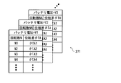
- FIG. 2 is a schematic diagram showing a configuration example of the phase correction table 271 shown in FIG.
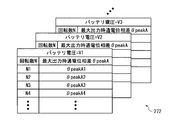
- FIG. 3 is a schematic diagram showing a configuration example of the energization control table 272 shown in FIG.
- FIG. 4 is a flowchart showing a flow of processing for creating the phase correction table 271 and the energization control table 272 using the A unit.
- the phase correction table 271 is a phase difference that is a difference between a phase in which the output voltage of the ACG 1 has a predetermined waveform and an input phase of a position sensor signal (position detection signal) input from the position sensor 13 and serves as a reference. It is a table (reference
- the battery voltage and the rotation speed of ACG1 are used as data relating to the driving state of ACG1.
- the predetermined waveform in the output voltage of ACG1 is a waveform at the time when the phase voltage in the output voltage of ACG1 zero-crosses as shown in FIG.
- phase difference that is the difference between the phase in which the output voltage of the ACG 1 shows a predetermined waveform and the input phase of the position sensor signal input from the position sensor 13 represents the transistors 241 to 241 of the three-phase inverter 240.
- the phase difference ⁇ TA can be expressed by, for example, a difference in electrical angle between phase voltages.
- phase correction table 271 shown in FIG. 2 the battery voltage is changed to V1, V2, V3,..., And the rotation speed is changed to N1, N2, N3,.
- the transistors 241 to 246 of the three-phase inverter 240 are all turned off, the phase differences ⁇ TA1, ⁇ TA2, ⁇ TA3,... Measured by the A unit are set to the voltages V1, V2, V3,. , N2, N3,...
- the energization control table 272 is a table that associates an energization phase difference (energization angle) for outputting predetermined power from the ACG 1 of the A unit serving as a reference with data related to the drive state of the ACG 1.
- the output power of the ACG 1 can be controlled by changing the phase of the phase voltage when switching the energization pattern in the three-phase inverter 240 by energization control (referred to as energization phase) as shown in FIG. 8, for example.
- energization phase referred to as energization phase
- the energization pattern in the three-phase inverter 240 is a combination of ON and OFF of the transistors 241 to 246.
- the energization phase difference ⁇ A is a phase difference up to a predetermined energization phase with a predetermined phase of the position sensor signal as a reference.
- the energization phase difference ⁇ A is obtained when the energization pattern is switched from the phase when the position sensor signal input from the position sensor 13 is binarized by the position sensor signal detection unit 21.
- the output power of ACG 1 can be maximized when the energization phase is ⁇ Wmax.
- the energization phase difference ⁇ A set in the energization control table 272 can be the maximum output energization phase difference ⁇ peakA for outputting the maximum power from the ACG 1.
- the maximum output energization phase difference ⁇ peakA is the energization phase difference ⁇ A corresponding to the phase ⁇ Wmax that outputs the maximum power.
- the output power of the ACG 1 is controlled to the maximum by performing energization control so that the energization phase difference becomes ⁇ peakA with reference to the phase at the time when the binarized signal of the position sensor signal falls. Can do.
- the phase in which the output voltage of ACG1 used when creating the phase correction table 271 shows a predetermined waveform is not limited to zero crossing, but a phase in which a predetermined voltage value passes at a rising edge, and a predetermined voltage value falls.
- the phase passing through can be arbitrarily set.
- the energization phase difference ⁇ A for outputting predetermined power from the ACG 1 used when creating the energization control table 272 is not limited to the phase at the maximum output, but when the output is zero or from the output zero to the maximum output It is also possible to correspond to an intermediate value up to or a phase when the ACG 1 is operated as an electric motor (that is, when the output is a negative value). In this case, a plurality of energization control tables 272 can be provided according to the output, for example.
- phase correction table 271 and the energization control table 272 using the A unit
- the flow of processing executed by an operator, a computer that executes a predetermined program, and the like. explain.
- a predetermined output voltage is determined from a predetermined waveform change of the position sensor 13 of the A unit while changing the rotation speed and the battery voltage within a predetermined range with all the transistors 241 to 246 of the inverter circuit section 24 turned off.
- the phase difference ⁇ TA until the waveform change is measured (step S11).
- a phase correction table 271 (FIG. 2) is created based on the measurement result in step S11 (step S12).
- energization control is executed while changing the rotation speed and the battery voltage within a predetermined range, and the energization phase difference ⁇ A is changed to measure the maximum output energization phase difference ⁇ peakA at which the output of the A unit is maximized ( Step S13).
- the energization control table 272 (FIG. 3) is created based on the measurement result in step S13.
- the phase correction table 271 created in step S12 and the energization control table 272 created in step S14 are stored in the storage unit 27 of the B unit.
- the calculation unit 26 shown in FIG. 1 is a signal indicating the ACG position output from the position sensor signal detection unit 21, a zero cross signal output from the output voltage detection unit 22, and a signal indicating the rotation number output from the rotation number determination unit 23.
- the battery voltage detection signal output from the battery voltage detection unit 28 is input.
- the calculation unit 26 controls the drive signal generation unit 25 with reference to the input signal and information stored in the storage unit 27.
- the calculation unit 26 controls the drive signal generation unit 25 with reference to the input signal and information stored in the storage unit 27, performs predetermined measurement, and corrects the phase difference ⁇ TAB data 273 based on the measurement result. Is calculated and stored in the storage unit 27.
- operation movement of the calculation part 26 is demonstrated.
- the calculation unit 26 measures the rotation speed and the battery voltage with all the transistors 241 to 246 of the inverter circuit unit 24 turned off, and from a predetermined waveform change of the position sensor 13 of the B unit.
- the phase difference ⁇ TB until the predetermined waveform change of the output voltage of ACG1 is measured (step S21).
- step S21 as shown in FIG. 7, the calculation unit 26 calculates the phase of the phase voltage and the phase voltage when the signal obtained by binarizing the position sensor signal by the position sensor signal detection unit 21 falls.
- the phase difference ⁇ TB from the phase at the time of zero crossing is measured.
- the calculation unit 26 refers to the phase correction table 271 stored in the storage unit 27, and acquires the phase difference ⁇ TA of the A unit corresponding to the rotation speed measured by the B unit and the battery voltage in step S21. (Step S22).
- the phase difference ( ⁇ TA) is a phase difference that varies depending on the mounting error ( ⁇ TAc) corresponding to the sensor mounting position of the reference unit A and the driving state of the reference unit A. It is a total value with ( ⁇ TAd).
- the phase difference ( ⁇ TB) is the sum of the mounting error ( ⁇ TBc) corresponding to the sensor mounting position of the unit B to be measured and the phase difference ( ⁇ TBd) that changes according to the driving state of the unit B to be measured. Value.
- FIG. 6 is a flowchart showing an operation example (processing for determining energization phase difference ⁇ B in energization control) of power generation device 100 (in the case of B unit) shown in FIG.
- the energization phase difference ⁇ B is the same as the energization phase difference ⁇ A when the signal obtained by binarizing the position sensor signal input from the position sensor 13 by the position sensor signal detection unit 21 falls. Is a phase difference from the phase to the phase at the time of switching the energization pattern.
- the calculation unit 26 When determining the energization phase difference ⁇ B used in the energization control for maximizing the output of ACG1 in the B unit, the calculation unit 26 first measures the rotation speed and battery voltage of ACG1 (step S31). Next, the calculation unit 26 refers to the energization control table 272 (FIG. 3), and obtains the maximum energization phase difference ⁇ peakA of the A unit corresponding to the rotation speed and the battery voltage measured by the B unit in step S31 ( Step S32).
- the power generation apparatus 100 controls the energization phase with ⁇ Wmax and the output of ACG1 is the maximum value as shown in FIG. Can be controlled.
- the storage unit 27 stores the phase correction table 271 (reference data) in which the phase difference ( ⁇ TA) of the reference unit is associated with the data related to the driving state.
- the calculation unit 26 measures the driving state of the measurement target B unit and measures the phase difference ( ⁇ TB) of the measurement target B unit corresponding to the driving state. Further, the calculation unit 26 acquires the phase difference ( ⁇ TA) of the A unit serving as a reference corresponding to the driving state with reference to the storage unit 27, and the measured phase difference ( ⁇ TB) and the acquired A unit serving as the reference.
- the correction phase difference ( ⁇ TAB ⁇ TA ⁇ TB), which is the difference from the phase difference ( ⁇ TA), is calculated.
- the embodiment of the present invention is not limited to the above-described embodiment.
- the embodiment of the present invention can be as follows.
- the phase correction table 271 (reference data) is configured as a three-dimensional table by using the battery voltage and the rotational speed shown in FIG.
- the configuration of the phase correction table 271 is not limited.
- the data relating to the driving state may be configured as either the battery voltage or the rotation speed
- the phase correction table 271 (reference data) may be configured as a two-dimensional table.
- the phase correction table 271 (reference data) may be configured based on the result of measuring the phase difference ⁇ TA by changing the battery voltage within a certain range with one rotation speed.
- the phase correction table 271 (reference data) may be configured based on the result of measuring the phase difference ⁇ TA by changing the rotation speed within a certain range with one battery voltage.
- the phase difference ⁇ TA is set with reference to the zero-cross point of the output voltage (phase voltage) of the ACG 1.
- the phase difference ⁇ TA may be set with reference to the zero-cross point of the phase current.
- the battery voltage may be a DC output voltage of the inverter circuit unit 24 (an output voltage of ACG1).
- phase difference ⁇ TA may be set with reference to a time point when a predetermined voltage (for example, several volts) or a predetermined current (for example, several amperes) is reached.
- a predetermined voltage for example, several volts
- a predetermined current for example, several amperes
- the battery voltage and the rotation speed are used as the data relating to the driving state.
- the temperature of the ACG 1, the temperature of the power generation control device 2, or the battery ambient temperature is added as an element (as a parameter)
- the phase difference ⁇ TA may be set.
- the measured temperature of the power generation control device 2 and the output voltage of ACG1 are used as parameters, and the measured three-phase output current of ACG1 passes a predetermined current (for example, 3A)
- a predetermined current for example, 3A
- the phase difference between the phase at the time when the signal is input and the input phase of the position sensor signal can be made the phase difference ⁇ TA.
- Generator 200 battery 1 ACG (generator) DESCRIPTION OF SYMBOLS 11 Stator 12 Rotor 13 Position sensor 2 Power generation control device 21 Position sensor signal detection part 22 Output voltage detection part 23 Rotational speed discrimination
- Inverter circuit part 240 Three-phase inverter 241 to 246 Transistor D1 Parasitic diode 25 Drive signal generation part 26 Calculation part 27 Storage Unit 271 Phase Correction Table 272 Energization Control Table 273 Correction Phase Difference ⁇ TAB Data 28 Battery Voltage Detection Unit
Landscapes
- Engineering & Computer Science (AREA)
- Power Engineering (AREA)
- Control Of Eletrric Generators (AREA)
Abstract
本実施形態の発電制御装置は、発電機のロータの回転位置を検出する位置センサが出力した位置検出信号を入力する入力部と、発電機が出力した3相交流を整流した直流電力をバッテリに供給するインバータ回路部と、発電機の出力電圧が所定の波形を示す位相と位置検出信号の位相との差分である位相差であって、基準となるユニットの位相差と駆動状態に関するデータとの対応付けされた基準データを記憶する記憶部と、測定対象のユニットの駆動状態を測定しかつ当該駆動状態に対応する測定対象のユニットの位相差を測定し、当該駆動状態に対応する基準となるユニットの位相差を記憶部を参照して取得し、測定した位相差と基準となるユニットの位相との差分である補正位相差を算出する算出部と、算出した補正位相差に応じて通電制御を行う駆動信号生成部とを備える。
Description
本発明は、発電制御装置、発電制御方法および発電装置に関する。
永久磁石でロータを構成するACG(Alternating Current Generator;発電機)を用いた発電装置は、ACGのロータの回転位置を表す位置センサ信号を出力する位置センサと、当該位置センサ信号に基づきインバータ回路を構成する各スイッチング素子の通電制御を行う駆動信号を出力する制御部とを備える(例えば、特許文献1)。バッテリの充電においてはステータ巻線の出力電流が最大となる位相領域での通電制御が求められる。出力電流が最大となる位相領域で通電制御を行うには、位置センサの検出精度を向上させることが望まれる。しかし、このような発電装置では、複数製造した場合、発電装置ごとに位置センサの取付位置が誤差により異なり、必ずしも正しい位置での測定が行われない。そのため、位置検出精度が低下してしまう。これに対し、特許文献1に記載されている発電装置では、以下のようにしてステータ巻線の誘起電圧を推定することで位置センサの取付誤差を推測し、推測結果に応じて補正した位相を使用して最大発電電力時の駆動信号を出力している。
すなわち、特許文献1に記載されている発電装置では、位置センサ信号の立ち下がりと、直接計測することが難しい誘起電圧のゼロクロス点の位相差Δθ3を、次のように推測することで、取付位置の誤差が推定される。まず、位置センサ信号の立ち下がりとACGの端子電圧の立ち上がりの位相差Δθ1が計測される。次に、ACGの端子電圧の立ち上がりと誘起電圧のゼロクロス点の位相差Δθ2が、等価回路を用いて推定されたり、回転数(回転速度に同じ)やバッテリ電圧をパラメータとする測定結果に基づいて作成されたマップを用いて推定されたりする。そして、位相差Δθ3が(Δθ3=Δθ1-Δθ2)の計算式で推測される。
しかしながら、特許文献1では、ステータ巻線の誘起電圧に対して位置センサの取付誤差を推測するが、そもそも誘起電圧を測定する手段は明示されていない。また、取付誤差Δθ3を決定するには、誘起電圧と誘起電圧以外の状態を同時に測定し、かつ、発電機の回転数や誘起電圧を可変にすることが必要である。例えば、3相信号のうち1相はオープンにして、残り2相を、電子負荷を間にして接続することで、誘起電圧を測定することは可能である。しかし、この方法では、3相信号のうち1相の位相と残り2相の位相とを比較するので、3相が120°毎に精度よく並んでいることが前提となる。また、測定する誘起電圧は、発電機内部の磁界を通して影響を受けるので、推測する取付誤差Δθ3の精度の低下を招いてしまう。このように、特許文献1に開示された技術では、推測する取付誤差Δθ3の精度の低下が生じてしまい、最大出力の制御ができていない。
そこで、本願は、位置検出精度を向上し、通電制御を精度よく行うことができる発電制御装置、発電制御方法および発電装置を提供することを目的とする。
上記課題を解決するため、本発明の一態様は、発電機のロータの回転位置を検出する位置センサが出力した位置検出信号を入力する位置検出信号入力部と、複数の整流素子と複数のスイッチング素子からなり、前記発電機から出力されるN相交流(N=1以上の整数)を整流した直流電力をバッテリに供給するインバータ回路部と、前記発電機の出力電圧が所定の波形を示す位相と前記位置センサから入力した前記位置検出信号の入力位相との差分である位相差であって、基準となるユニットの前記位相差と駆動状態に関するデータとの対応付けされた基準データを記憶する記憶部と、測定対象のユニットの駆動状態を測定するとともに当該駆動状態に対応する前記測定対象のユニットの前記位相差を測定し、当該駆動状態に対応する前記基準となるユニットの前記位相差を前記記憶部を参照して取得し、測定した前記位相差と前記基準となるユニットの前記位相差との差分である補正位相差を算出する算出部と、前記算出部が算出した前記補正位相差に応じて前記複数のスイッチング素子の通電制御を行う駆動信号生成部とを備えることを特徴とする発電制御装置である。
また、本発明の一態様は、上記発電制御装置であって、前記基準となるユニットの前記位相差は、前記基準となるユニットの前記発電機が出力したN相交流(N=1以上の整数)のゼロクロスを示す位相と前記基準となるユニットの前記位置センサから入力した前記位置検出信号の入力位相との位相差であって、当該位相差は、前記基準となるユニットのセンサ取付位置に対応する取付誤差と、前記基準となるユニットの駆動状態に応じて変化する位相差との合計の値であり、前記測定対象のユニットの前記位相差は、前記測定対象のユニットの前記発電機が出力したN相交流(N=1以上の整数)のゼロクロスを示す位相と前記測定対象のユニットの前記位置センサから入力した前記位置検出信号の入力位相との位相差であって、当該位相差は、前記測定対象のユニットのセンサ取付位置に対応する取付誤差と、前記測定対象のユニットの駆動状態に応じて変化する位相差との合計の値であることを特徴とする。
また、本発明の一態様は、上記発電制御装置であって、前記駆動状態は、前記発電機の回転数および前記バッテリの電圧の少なくとも一方をパラメータとして設定されることを特徴とする。
また、本発明の一態様は、発電機のロータの回転位置を検出する位置センサが出力した位置検出信号を入力する位置検出信号入力部と、複数の整流素子と複数のスイッチング素子からなり、前記発電機から出力されるN相交流(N=1以上の整数)を整流した直流電力をバッテリに供給するインバータ回路部と、前記発電機の出力電圧が所定の波形を示す位相と前記位置センサから入力した前記位置検出信号の入力位相との差分である位相差であって、基準となるユニットの前記位相差と駆動状態に関するデータとの対応付けされた基準データを記憶する記憶部と、測定対象のユニットの駆動状態を測定するとともに当該駆動状態に対応する前記測定対象のユニットの前記位相差を測定し、当該駆動状態に対応する前記基準となるユニットの前記位相差を前記記憶部を参照して取得し、測定した前記位相差と前記基準となるユニットの前記位相差との差分である補正位相差を算出する算出部とを用い、駆動信号生成部によって、前記算出部が算出した前記補正位相差に応じて前記複数のスイッチング素子の通電制御を行うことを特徴とする発電制御方法である。
また、本発明の一態様は、前記発電機と、前記位置センサと、上記発電制御装置とを備える発電装置である。
本発明の実施形態によれば、記憶部は、基準となるユニットの位相差と駆動状態に関するデータとの対応付けされた基準データを記憶する。また、算出部は、測定対象のユニットの駆動状態を測定するとともに当該駆動状態に対応する測定対象のユニットの位相差を測定する。さらに、算出部は、当該駆動状態に対応する基準となるユニットの位相差を記憶部を参照して取得し、測定した位相差と取得した基準となるユニットの位相差との差分である補正位相差を算出する。この構成によれば、記憶部が記憶する基準となるユニットの位相差と、測定対象のユニットで測定された位相差とを直接比較して差分をとることで補正位相差が算出される。したがって、基準となるユニットの位相差と測定対象のユニットの位相差との差分を取ることで誘起電圧に係る位相差を互いに打ち消すことができる。よって、誘起電圧に係る位相差を推定する必要がない。それ故、本発明の実施形態によれば、位置検出精度を向上し、通電制御を精度よく行うことができる。
以下、図面を参照して本発明の実施形態について説明する。図1は、本発明の一実施形態に係る発電装置100の構成例を示すブロック図である。図1に示す発電装置100は、ACG(発電機)1と、発電制御装置2とを備える。発電装置100は、発電制御装置2によってACG1の出力を制御し、バッテリ200や図示していない他の電気負荷へ供給する直流電力を制御する。一例として、本実施形態の発電装置100とバッテリ200は、バイク、自動二輪車等の車両に搭載された充電システムを構成するものとすることができる。
ACG1は、ステータ11と、ロータ12と、位置センサ13とを備える。ただし、位置センサ13は、発電制御装置2に含まれる構成としてもよい。ステータ11は、電機子コアと電機子コアに巻回された3相巻線とを備えて構成されている。3相巻線は、スター結線であってもよいし、デルタ結線であってもよい。3相巻線の各相をU、VおよびW相とする。ロータ12は、ステータ11に対してN極とS極を交互に向き合うように配置された永久磁石を備えて構成されている。ロータ12は、例えば、エンジンのクランクシャフトに直結されていて、エンジンを動力源として回転駆動される。位置センサ13は、ロータ12の回転位置を検出するセンサであり。例えばロータ12の磁極の変化に応じて変化する信号を位置センサ信号として出力する。なお、ステータ11は、3相交流に限らず、N相交流(N=1以上の整数)を出力するものとすることができる。
発電制御装置2は、位置センサ信号検出部(位置検出信号入力部)21と、出力電圧検出部22と、回転数判別部23と、インバータ回路部24と、駆動信号生成部25と、算出部26と、記憶部27と、バッテリ電圧検出部28とを備える。
位置センサ信号検出部21は、位置センサ13が出力した位置センサ信号を入力し、位置センサ信号に対して波形成形処理を行い、ACG位置に対応する2値信号に変換して、変換した結果を出力する。出力電圧検出部22は、ACG1の3相電圧を入力し、各相電圧のゼロクロス点を表すゼロクロス信号を出力する。
回転数判別部23は、位置センサ信号検出部21が出力したACG位置を表す信号または出力電圧検出部22が出力したゼロクロス信号に基づきACG1の回転数を算出し、算出した回転数を表す信号を出力する。なお、図1では、回転数判別部23に対して、ACG位置を表す信号とゼロクロス信号の2つの信号が入力されるように示しているが、いずれか一方の信号が入力されていればよい。
図1に示す構成例では、インバータ回路部24は3相インバータ240を備える。3相インバータ240は、6個のトランジスタ(スイッチング素子)241~246を有する。インバータ回路部24は、駆動信号生成部25から入力された駆動信号に基づき、ACG1が出力した3相交流の位相に同期させて6個のトランジスタ241~246を通電制御することで、バッテリ200等へ出力される直流電力を制御する。図1に示す構成例では、トランジスタ241~246がMOSFET(金属酸化膜半導体電界効果トランジスタ)である。ただし、トランジスタの種類に限定はない。図1に示す例では、トランジスタ241~243の各ドレインはバッテリ200の正極に接続され、トランジスタ244~246の各ソースはバッテリ200の負極に接続されている(バッテリ200と共通に接地されている)。トランジスタ241のソースとトランジスタ244のドレインはACG1のU相出力に接続されている。トランジスタ242のソースとトランジスタ245のドレインはACG1のV相出力に接続されている。トランジスタ243のソースとトランジスタ246のドレインはACG1のW相出力に接続されている。また、トランジスタ241~246の各寄生ダイオードD1(整流素子)は、トランジスタ241~246がオフされた状態で、3相全波整流回路を構成する。ただし、3相全波整流回路を構成するダイオードは個別のダイオードであってもよい。なお、インバータ回路部24は、3相フルブリッジ回路に限らず、Hブリッジ回路、4相ブリッジ回路等、ACG1が出力したN相交流(N=1以上の整数)を整流することができる回路を備えていればよい。
駆動信号生成部25は、算出部26から入力された所定の制御信号に基づき、トランジスタ241~246のゲート・ソース間に入力される6個の駆動信号を生成して出力する。駆動信号生成部25が出力する各駆動信号は、トランジスタ241~246を個別にオンまたはオフする。なお、各駆動信号がトランジスタ241~246をオンまたはオフにする制御には、PWM(パルス幅変調)制御も含む。
バッテリ電圧検出部28は、バッテリ200の端子電圧を入力し、所定の分圧比で分圧した信号をバッテリ電圧検出信号として出力する。
記憶部27は、位相補正用テーブル271、通電制御用テーブル272および補正位相差ΔθTABデータ273を記憶する。なお、本実施形態の発電装置100は、基準となるユニット(以下、Aユニットと称する)として用いられる場合と、測定対象のユニット(以下、Bユニットと称する)として用いられる場合がある。Aユニットは、位相補正用テーブル271および通電制御用テーブル272を作成する際に用いられる発電装置100である。Bユニットとして用いられる場合の発電装置100は、Aユニットを用いて作成された記憶部27が記憶する位相補正用テーブル271を参照して補正位相差ΔθTABデータ273を算出する。ここで、補正位相差ΔθTABデータ273は、Aユニットの位置センサ13が出力する位置センサ信号とBユニットの位置センサ13が出力する位置センサ信号との位相差(すなわち取付位置の誤差)に対応する情報である。補正位相差ΔθTABデータ273は、例えば初期値はゼロに設定され、その後、Bユニットで所定の測定を実施した結果に基づいてBユニットに対応した値に設定される。また、Bユニットは、Aユニットを用いて作成された記憶部27が記憶する通電制御用テーブル272を参照し、自ら算出した補正位相差ΔθTABデータ273を用いてインバータ回路部24による通電制御を実行する。例えば、Aユニットは試作段階の発電装置100であり、Bユニットは製品として出荷される発電装置100である。したがって、Aユニットでは、記憶部27が、例えば、位相補正用テーブル271、通電制御用テーブル272および補正位相差ΔθTABデータ273を記憶していない場合がある。また、Bユニットでは、記憶部27が、例えば、位相補正用テーブル271および通電制御用テーブル272を予め記憶するとともに、補正位相差ΔθTABデータ273を記憶あるいは更新して記憶することになる。なお、Aユニットは、同一仕様のACG1に対して1台だけ設定してもよいし、複数台設定してもよい。複数台設定する場合には、後述する位相補正用テーブル271や通電制御用テーブル272の内容を例えば複数台の特性の平均値や中央値に基づいて設定することができる。
次に、図2~図4等を参照して、位相補正用テーブル271および通電制御用テーブル272の構成例について説明する。図2は、図1に示す位相補正用テーブル271の構成例を示す模式図である。図3は、図1に示す通電制御用テーブル272の構成例を示す模式図である。図4は、Aユニットを用いて位相補正用テーブル271および通電制御用テーブル272を作成する処理の流れを示すフローチャートである。
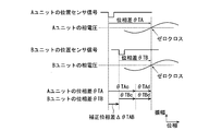
位相補正用テーブル271は、ACG1の出力電圧が所定の波形を示す位相と位置センサ13から入力した位置センサ信号(位置検出信号)の入力位相との差分である位相差であって、基準となるAユニットの位相差(θTA)とACG1の駆動状態に関するデータとを対応付けるテーブル(基準データ)である。図2に示す例では、ACG1の駆動状態に関するデータとして、バッテリ電圧とACG1の回転数を用いている。また、ACG1の出力電圧における所定の波形は、3相インバータ240のトランジスタ241~246をすべてオフした状態で、図7に示すように、ACG1の出力電圧における相電圧がゼロクロスする時点の波形である。また、ACG1の出力電圧が所定の波形を示す位相と位置センサ13から入力した位置センサ信号の入力位相との差分である位相差は、図7に示すように、3相インバータ240のトランジスタ241~246をすべてオフした状態で、位置センサ信号を位置センサ信号検出部21で2値化した信号が立ち下がった時点の相電圧の位相と、相電圧がゼロクロスする時点の位相との位相差θTAである。位相差θTAは、例えば相電圧の電気角の差で表すことができる。図2に示す位相補正用テーブル271は、バッテリ電圧をV1、V2、V3、…と変化させるとともに、各電圧V1、V2、V3、…で回転数をN1、N2、N3、…と変化させたときに、3相インバータ240のトランジスタ241~246をすべてオフした状態でAユニットで計測された位相差θTA1、θTA2、θTA3、…とを各電圧V1、V2、V3、…と各回転数をN1、N2、N3、…とに対応づけるテーブルである。
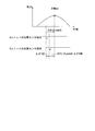
一方、通電制御用テーブル272は、基準となるAユニットのACG1から所定の電力を出力させるための通電位相差(通電角)と、ACG1の駆動状態に関するデータとを対応付けるテーブルである。ACG1の出力電力は、例えば図8に示すように、通電制御によって3相インバータ240における通電パターンを切り替える時の相電圧の位相(これを通電位相と呼ぶ)を変化させることで制御することができる。ここで、3相インバータ240における通電パターンとは、トランジスタ241~246のオンまたはオフの組み合わせである。また、通電位相差θAとは、位置センサ信号の所定の位相を基準とする所定の通電位相までの位相差である。図8に示す例では、通電位相差θAは、位置センサ13から入力した位置センサ信号を位置センサ信号検出部21で2値化した信号が立ち下がった時点の位相から、通電パターンを切り替える時点の位相までの位相差である。また、図8に示す例では、通電位相をθWmaxとした場合にACG1の出力電力を最大とすることができる。また、例えば、通電制御用テーブル272に設定される通電位相差θAは、ACG1から最大電力を出力させるための最大出力時通電位相差θpeakAとすることができる。最大出力時通電位相差θpeakAは、最大電力を出力する位相θWmaxに対応する通電位相差θAである。Aユニットでは、位置センサ信号を2値化した信号が立ち下がった時点の位相を基準として、通電位相差がθpeakAとなるように通電制御を行うことで、ACG1の出力電力を最大に制御することができる。
また、通電制御用テーブル272に設定されるACG1の駆動状態に関するデータとしては、例えばバッテリ電圧とACG1の回転数を用いることができる。図3に示す通電制御用テーブル272は、バッテリ電圧をV1、V2、V3、…と変化させるとともに、各電圧V1、V2、V3、…で回転数をN1、N2、N3、…と変化させたときに、Aユニットで計測された最大出力時位相差θpeakA1、θpeakA2、θpeakA3、…を、各電圧V1、V2、V3、…と各回転数N1、N2、N3、…とに対応づけるテーブルである。
なお、位相補正用テーブル271を作成する際に使用するACG1の出力電圧が所定の波形を示す位相は、ゼロクロスに限らず、所定の電圧値を立ち上がりで通過する位相、所定の電圧値を立ち下がりで通過する位相等、任意に設定することができる。また、通電制御用テーブル272を作成する際に使用するACG1から所定の電力を出力させるための通電位相差θAは、最大出力時の位相に限らず、出力がゼロのときや出力ゼロから最大出力までの中間の値、あるいはACG1を電動機として動作させるとき(すなわち出力が負の値となるとき)の位相に対応するものとしてもよい。この場合、通電制御用テーブル272は、例えば出力に応じて複数設けることができる。
次に、図4を参照して、Aユニットを用いて位相補正用テーブル271および通電制御用テーブル272を作成する際に、操作者、所定のプログラムを実行するコンピュータ等が実行する処理の流れについて説明する。この処理では、まず、インバータ回路部24のトランジスタ241~246をすべてオフした状態で回転数とバッテリ電圧を所定の範囲で変化させながらAユニットの位置センサ13の所定の波形変化から出力電圧の所定の波形変化までの位相差θTAを測定する(ステップS11)。次に、ステップS11での測定結果に基づいて位相補正用テーブル271(図2)を作成する(ステップS12)。
次に、回転数とバッテリ電圧を所定の範囲で変化させながら通電制御を実行し、通電位相差θAを変化させて、Aユニットの出力が最大となる最大出力時通電位相差θpeakAを測定する(ステップS13)。次に、ステップS13での測定結果に基づいて通電制御用テーブル272(図3)を作成する。ステップS12で作成された位相補正用テーブル271とステップS14で作成された通電制御用テーブル272は、Bユニットの記憶部27に記憶される。
一方、図1に示す算出部26は、位置センサ信号検出部21が出力したACG位置を表す信号、出力電圧検出部22が出力したゼロクロス信号、回転数判別部23が出力した回転数を表す信号、および、バッテリ電圧検出部28が出力したバッテリ電圧検出信号を入力する。また、算出部26は、入力信号や記憶部27に記憶されている情報を参照して駆動信号生成部25を制御する。また、算出部26は、入力信号や記憶部27に記憶されている情報を参照して駆動信号生成部25を制御するとともに、所定の測定を行い、測定結果に基づいて補正位相差ΔθTABデータ273を算出して記憶部27へ記憶する。ここで、図5、図6等を参照して、算出部26の動作について説明する。
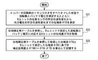
図5は、図1に示す発電装置100(Bユニットの場合)の動作例(補正位相差ΔθTAB273を算出する処理)を示すフローチャートである。なお、この場合、位相補正用テーブル271には図7を参照して説明したように、位置センサ信号を位置センサ信号検出部21で2値化した信号が立ち下がった時点の相電圧の位相と、相電圧がゼロクロスする時点の位相との位相差θTAが設定されているものとする。
補正位相差ΔθTAB273を算出する場合、算出部26は、インバータ回路部24のトランジスタ241~246をすべてオフした状態で回転数とバッテリ電圧を測定するとともにBユニットの位置センサ13の所定の波形変化からACG1の出力電圧の所定の波形変化までの位相差θTBを測定する(ステップS21)。この場合、ステップS21において、算出部26は、図7に示すように、位置センサ信号を位置センサ信号検出部21で2値化した信号が立ち下がった時点の相電圧の位相と、相電圧がゼロクロスする時点の位相との位相差θTBを測定する。
次に、算出部26は、記憶部27に記憶されている位相補正用テーブル271を参照し、ステップS21においてBユニットで測定した回転数とバッテリ電圧に対応するAユニットの位相差θTAを取得する(ステップS22)。
次に、算出部26は、ステップS22において位相補正用テーブル271を参照して取得した位相差θTAと、ステップS21においてBユニットで測定した位相差θTBに基づき補正位相差ΔθTAB(=θTA-θTB)を算出して、記憶部27に補正位相差ΔθTABデータ273として記憶する(ステップS23)。なお、図7に示すように、位相差(θTA)は、基準となるユニットAのセンサ取付位置に対応する取付誤差(θTAc)と、基準となるユニットAの駆動状態に応じて変化する位相差(θTAd)との合計の値である。また、位相差(θTB)は、測定対象のユニットBのセンサ取付位置に対応する取付誤差(θTBc)と、測定対象のユニットBの駆動状態に応じて変化する位相差(θTBd)との合計の値である。
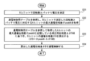
次に、図6は、図1に示す発電装置100(Bユニットの場合)の動作例(通電制御において通電位相差θBを決定する処理)を示すフローチャートである。この場合、通電位相差θBは、図8に示すように、通電位相差θAと同様、位置センサ13から入力した位置センサ信号を位置センサ信号検出部21で2値化した信号が立ち下がった時点の位相から、通電パターンを切り替える時点の位相までの位相差である。Bユニットにおいて、ACG1の出力を最大にする通電制御において用いる通電位相差θBを決定する場合、算出部26は、まず、ACG1の回転数とバッテリ電圧を測定する(ステップS31)。次に、算出部26は、通電制御用テーブル272(図3)を参照し、ステップS31においてBユニットで測定した回転数とバッテリ電圧に対応するAユニットの最大時通電位相差θpeakAを取得する(ステップS32)。
次に、算出部26は、ステップS32において通電制御用テーブル272を参照して取得したAユニットの最大時通電位相差θpeakAと記憶している補正位相差ΔθTABデータ273に基づき、Bユニットの通電位相差θBを(θB=θpeakA-ΔθTAB)式にて算出する(ステップS33)。次に、算出部26は、ステップS33において算出した通電位相差θBで通電制御を実行する(ステップS34)。
以上のように通電位相差θBを決定して通電制御を行うことで、発電装置100(Bユニット)は、図8に示すように、通電位相をθWmaxで制御して、ACG1の出力を最大値に制御することができる。
本実施形態によれば、記憶部27は、基準となるユニットの位相差(θTA)と駆動状態に関するデータとの対応付けされた位相補正用テーブル271(基準データ)を記憶する。また、算出部26は、測定対象のBユニットの駆動状態を測定するとともに当該駆動状態に対応する測定対象のBユニットの位相差(θTB)を測定する。さらに、算出部26は、当該駆動状態に対応する基準となるAユニットの位相差(θTA)を記憶部27を参照して取得し、測定した位相差(θTB)と取得した基準となるAユニットの位相差(θTA)との差分である補正位相差(ΔθTAB=θTA-θTB)を算出する。この構成によれば、記憶部27が記憶する基準となるAユニットの位相差(θTA)と、測定対象のBユニットで測定された位相差(θTB)とを直接比較して差分をとることで補正位相差(ΔθTAB)が算出される。したがって、基準となるAユニットの位相差(θTA)と測定対象のBユニットの位相差(θTB)との差分を取ることで誘起電圧に係る位相差を互いに打ち消すことができる。よって、誘起電圧に係る位相差を推定する必要がない。それ故、本実施形態によれば、位置検出精度を向上し、通電制御を精度よく行うことができる。
なお、本実施形態においては、例えば、図1に示す各ブロックの一部または全部を分割したり、他のブロックの一部または全部と統合したりしてもよい。すなわち、例えば、算出部26と回転数判別部23と記憶部27の各一部または各全部を統合することができる。また、発電制御装置2と位置センサ13と一体的に構成し、上述したように発電制御装置2と位置センサ13とを組み合わせものが発電制御装置2であるとしてもよい。
また、本発明の実施の形態は、上記の実施形態に限定されない。例えば、本発明の実施形態は、次のようなものとすることができる。
(1)上記実施形態では、駆動状態に関するデータとして図2に示すバッテリ電圧と回転数とを用いることで位相補正用テーブル271(基準データ)を3次元テーブルとして構成している。しかし、位相補正用テーブル271の構成は限定されず、例えば、駆動状態に関するデータをバッテリ電圧と回転数のいずれか一方として、位相補正用テーブル271(基準データ)を2次元テーブルとして構成してもよい。例えば、回転数を1つにしてバッテリ電圧を一定の範囲で変化させ、位相差θTAを測定した結果に基づいて位相補正用テーブル271(基準データ)を構成してもよい。あるいは、バッテリ電圧を1つにして回転数を一定の範囲で変化させ、位相差θTAを測定した結果に基づいて位相補正用テーブル271(基準データ)を構成してもよい。
(2)上記実施形態では、位相差θTAをACG1の出力電圧(相電圧)のゼロクロス点を基準として設定したが、相電流のゼロクロス点を基準として設定してもよい。また、バッテリ電圧は、インバータ回路部24の直流出力電圧(ACG1の出力電圧)としてもよい。
(3)また、ゼロクロス点に限らず、所定電圧(例えば数ボルト)あるいは所定電流(例えば数アンペア)となる時点を基準として位相差θTAを設定してもよい。
(4)上記実施形態では、駆動状態に関するデータとしてバッテリ電圧と回転数とを用いているが、例えばACG1の温度や発電制御装置2の温度、あるいはバッテリ周囲温度等を要素として(パラメータとして)加えて、位相差θTAを設定してもよい。
例えば、(1)~(4)の組み合わせから、計測した発電制御装置2の温度とACG1の出力電圧をパラメータとするとともに、計測したACG1の三相出力電流が所定の電流(例えば3A)を通過する時点の位相と位置センサ信号の入力位相との位相差を位相差θTAとすることができる。
以上、この発明の実施形態を図面を参照して詳述してきたが、具体的な構成はこの実施形態に限られるものではなく、この発明の要旨を逸脱しない範囲の設計等も含まれる。
100 発電装置
200 バッテリ
1 ACG(発電機)
11 ステータ
12 ロータ
13 位置センサ
2 発電制御装置
21 位置センサ信号検出部
22 出力電圧検出部
23 回転数判別部
24 インバータ回路部
240 3相インバータ
241~246 トランジスタ
D1 寄生ダイオード
25 駆動信号生成部
26 算出部
27 記憶部
271 位相補正用テーブル
272 通電制御用テーブル
273 補正位相差ΔθTABデータ
28 バッテリ電圧検出部
200 バッテリ
1 ACG(発電機)
11 ステータ
12 ロータ
13 位置センサ
2 発電制御装置
21 位置センサ信号検出部
22 出力電圧検出部
23 回転数判別部
24 インバータ回路部
240 3相インバータ
241~246 トランジスタ
D1 寄生ダイオード
25 駆動信号生成部
26 算出部
27 記憶部
271 位相補正用テーブル
272 通電制御用テーブル
273 補正位相差ΔθTABデータ
28 バッテリ電圧検出部
Claims (5)
- 発電機のロータの回転位置を検出する位置センサが出力した位置検出信号を入力する位置検出信号入力部と、
複数の整流素子と複数のスイッチング素子からなり、前記発電機から出力されるN相交流(N=1以上の整数)を整流した直流電力をバッテリに供給するインバータ回路部と、
前記発電機の出力電圧が所定の波形を示す位相と前記位置センサから入力した前記位置検出信号の入力位相との差分である位相差であって、基準となるユニットの前記位相差と駆動状態に関するデータとの対応付けされた基準データを記憶する記憶部と、
測定対象のユニットの駆動状態を測定するとともに当該駆動状態に対応する前記測定対象のユニットの前記位相差を測定し、当該駆動状態に対応する前記基準となるユニットの前記位相差を前記記憶部を参照して取得し、測定した前記位相差と前記基準となるユニットの前記位相差との差分である補正位相差を算出する算出部と、
前記算出部が算出した前記補正位相差に応じて前記複数のスイッチング素子の通電制御を行う駆動信号生成部と
を備えることを特徴とする発電制御装置。 - 前記基準となるユニットの前記位相差は、
前記基準となるユニットの前記発電機が出力したN相交流(N=1以上の整数)のゼロクロスを示す位相と前記基準となるユニットの前記位置センサから入力した前記位置検出信号の入力位相との位相差であって、
当該位相差は、前記基準となるユニットのセンサ取付位置に対応する取付誤差と、前記基準となるユニットの駆動状態に応じて変化する位相差との合計の値であり、
前記測定対象のユニットの前記位相差は、
前記測定対象のユニットの前記発電機が出力したN相交流(N=1以上の整数)のゼロクロスを示す位相と前記測定対象のユニットの前記位置センサから入力した前記位置検出信号の入力位相との位相差であって、
当該位相差は、前記測定対象のユニットのセンサ取付位置に対応する取付誤差と、前記測定対象のユニットの駆動状態に応じて変化する位相差との合計の値である
ことを特徴とする請求項1に記載の発電制御装置。 - 前記駆動状態は、前記発電機の回転数および前記バッテリの電圧の少なくとも一方をパラメータとして設定される
ことを特徴とする請求項2に記載の発電制御装置。 - 発電機のロータの回転位置を検出する位置センサが出力した位置検出信号を入力する位置検出信号入力部と、
複数の整流素子と複数のスイッチング素子からなり、前記発電機から出力されるN相交流(N=1以上の整数)を整流した直流電力をバッテリに供給するインバータ回路部と、
前記発電機の出力電圧が所定の波形を示す位相と前記位置センサから入力した前記位置検出信号の入力位相との差分である位相差であって、基準となるユニットの前記位相差と駆動状態に関するデータとの対応付けされた基準データを記憶する記憶部と、
測定対象のユニットの駆動状態を測定するとともに当該駆動状態に対応する前記測定対象のユニットの前記位相差を測定し、当該駆動状態に対応する前記基準となるユニットの前記位相差を前記記憶部を参照して取得し、測定した前記位相差と前記基準となるユニットの前記位相差との差分である補正位相差を算出する算出部とを用い、
駆動信号生成部によって、前記算出部が算出した前記補正位相差に応じて前記複数のスイッチング素子の通電制御を行う
ことを特徴とする発電制御方法。 - 前記発電機と、
前記位置センサと、
請求項1から3のいずれか1項に記載の発電制御装置と
を備える発電装置。
Priority Applications (2)
| Application Number | Priority Date | Filing Date | Title |
|---|---|---|---|
| PCT/JP2016/081964 WO2018078783A1 (ja) | 2016-10-27 | 2016-10-27 | 発電制御装置、発電制御方法および発電装置 |
| JP2017555610A JP6383884B1 (ja) | 2016-10-27 | 2016-10-27 | 発電制御装置、発電制御方法および発電装置 |
Applications Claiming Priority (1)
| Application Number | Priority Date | Filing Date | Title |
|---|---|---|---|
| PCT/JP2016/081964 WO2018078783A1 (ja) | 2016-10-27 | 2016-10-27 | 発電制御装置、発電制御方法および発電装置 |
Publications (1)
| Publication Number | Publication Date |
|---|---|
| WO2018078783A1 true WO2018078783A1 (ja) | 2018-05-03 |
Family
ID=62023243
Family Applications (1)
| Application Number | Title | Priority Date | Filing Date |
|---|---|---|---|
| PCT/JP2016/081964 Ceased WO2018078783A1 (ja) | 2016-10-27 | 2016-10-27 | 発電制御装置、発電制御方法および発電装置 |
Country Status (2)
| Country | Link |
|---|---|
| JP (1) | JP6383884B1 (ja) |
| WO (1) | WO2018078783A1 (ja) |
Citations (3)
| Publication number | Priority date | Publication date | Assignee | Title |
|---|---|---|---|---|
| JPH0919194A (ja) * | 1995-04-24 | 1997-01-17 | Nippondenso Co Ltd | 車両用同期発電装置及びその励磁制御方法 |
| JP2009100624A (ja) * | 2007-10-19 | 2009-05-07 | Kokusan Denki Co Ltd | 発電装置 |
| JP2012005246A (ja) * | 2010-06-17 | 2012-01-05 | Shindengen Electric Mfg Co Ltd | 充電制御装置 |
-
2016
- 2016-10-27 WO PCT/JP2016/081964 patent/WO2018078783A1/ja not_active Ceased
- 2016-10-27 JP JP2017555610A patent/JP6383884B1/ja active Active
Patent Citations (3)
| Publication number | Priority date | Publication date | Assignee | Title |
|---|---|---|---|---|
| JPH0919194A (ja) * | 1995-04-24 | 1997-01-17 | Nippondenso Co Ltd | 車両用同期発電装置及びその励磁制御方法 |
| JP2009100624A (ja) * | 2007-10-19 | 2009-05-07 | Kokusan Denki Co Ltd | 発電装置 |
| JP2012005246A (ja) * | 2010-06-17 | 2012-01-05 | Shindengen Electric Mfg Co Ltd | 充電制御装置 |
Also Published As
| Publication number | Publication date |
|---|---|
| JP6383884B1 (ja) | 2018-08-29 |
| JPWO2018078783A1 (ja) | 2018-10-25 |
Similar Documents
| Publication | Publication Date | Title |
|---|---|---|
| JP4900738B2 (ja) | 電動機駆動制御装置 | |
| JP4513536B2 (ja) | インバータ装置 | |
| JP6030142B2 (ja) | 電気モーター又は発電機 | |
| JP5610651B2 (ja) | ブラシレスモータ制御装置、およびブラシレスモータ制御方法 | |
| CN101951213B (zh) | 永磁同步电动机的控制装置以及控制方法 | |
| WO2012153637A1 (ja) | ブラシレスモータ制御装置、およびブラシレスモータ制御方法 | |
| US20140152215A1 (en) | Electric drive unit | |
| US8796979B2 (en) | Apparatus for driving brushless DC motor | |
| KR102331849B1 (ko) | Bldc 모터 제어장치 및 방법 | |
| US12255558B2 (en) | Motor controller, motor system and method for controlling motor | |
| KR20150044304A (ko) | 모터의 구동장치 및 그 제어방법 | |
| JP6542304B2 (ja) | 回転電機の制御装置及び制御方法 | |
| JP2012186911A (ja) | モータ制御装置 | |
| JP6383884B1 (ja) | 発電制御装置、発電制御方法および発電装置 | |
| KR20140090470A (ko) | 전동기 구동장치 | |
| US20140055066A1 (en) | Brushless motor control device and brushless motor control method | |
| CN111434025B (zh) | 用于确定机动车辆中电机的转子角的方法 | |
| JP5153241B2 (ja) | 整流回路 | |
| US20150130391A1 (en) | Motor drive controller and motor drive control method, and motor system using the same | |
| JP5614908B2 (ja) | ブラシレスモータ制御装置、およびブラシレスモータ制御方法 | |
| JP6574711B2 (ja) | 永久磁石同期電動機のインダクタンス測定方法 | |
| CN104811103A (zh) | 一种扩展ecm电机转速范围的控制方法 | |
| WO2023068012A1 (ja) | モータ制御装置 | |
| JP2012191731A (ja) | モータの制御装置 | |
| JP6741359B2 (ja) | 電力変換装置及び電力変換方法 |
Legal Events
| Date | Code | Title | Description |
|---|---|---|---|
| WWE | Wipo information: entry into national phase |
Ref document number: 2017555610 Country of ref document: JP |
|
| 121 | Ep: the epo has been informed by wipo that ep was designated in this application |
Ref document number: 16920424 Country of ref document: EP Kind code of ref document: A1 |
|
| NENP | Non-entry into the national phase |
Ref country code: DE |
|
| 122 | Ep: pct application non-entry in european phase |
Ref document number: 16920424 Country of ref document: EP Kind code of ref document: A1 |