WO2018074472A1 - 車軸軸受メンテナンスシステム - Google Patents
車軸軸受メンテナンスシステム Download PDFInfo
- Publication number
- WO2018074472A1 WO2018074472A1 PCT/JP2017/037535 JP2017037535W WO2018074472A1 WO 2018074472 A1 WO2018074472 A1 WO 2018074472A1 JP 2017037535 W JP2017037535 W JP 2017037535W WO 2018074472 A1 WO2018074472 A1 WO 2018074472A1
- Authority
- WO
- WIPO (PCT)
- Prior art keywords
- axle bearing
- maintenance
- maintenance data
- identification information
- communication
- Prior art date
- Legal status (The legal status is an assumption and is not a legal conclusion. Google has not performed a legal analysis and makes no representation as to the accuracy of the status listed.)
- Ceased
Links
Images


Classifications
-
- G—PHYSICS
- G01—MEASURING; TESTING
- G01M—TESTING STATIC OR DYNAMIC BALANCE OF MACHINES OR STRUCTURES; TESTING OF STRUCTURES OR APPARATUS, NOT OTHERWISE PROVIDED FOR
- G01M13/00—Testing of machine parts
- G01M13/04—Bearings
-
- G—PHYSICS
- G01—MEASURING; TESTING
- G01M—TESTING STATIC OR DYNAMIC BALANCE OF MACHINES OR STRUCTURES; TESTING OF STRUCTURES OR APPARATUS, NOT OTHERWISE PROVIDED FOR
- G01M17/00—Testing of vehicles
- G01M17/08—Railway vehicles
-
- G—PHYSICS
- G06—COMPUTING OR CALCULATING; COUNTING
- G06Q—INFORMATION AND COMMUNICATION TECHNOLOGY [ICT] SPECIALLY ADAPTED FOR ADMINISTRATIVE, COMMERCIAL, FINANCIAL, MANAGERIAL OR SUPERVISORY PURPOSES; SYSTEMS OR METHODS SPECIALLY ADAPTED FOR ADMINISTRATIVE, COMMERCIAL, FINANCIAL, MANAGERIAL OR SUPERVISORY PURPOSES, NOT OTHERWISE PROVIDED FOR
- G06Q10/00—Administration; Management
Definitions
- This invention relates to an axle bearing maintenance system that manages and analyzes maintenance data of axle bearings of railway vehicles.
- the maintenance operation is generally an operation of removing the axle bearing from the wheel shaft, disassembling, cleaning, inspecting and reassembling, and then reassembling the wheel shaft.
- identification information printed on bearing parts is visually checked for each maintenance process, and recorded and recorded on a paper medium together with measured maintenance data.
- accumulated maintenance data is used as confirmation of maintenance history.
- vibration detection data is sent to a server by using a portable communication / information processing terminal such as a smartphone or a tablet terminal (for example, a patent) Reference 1).
- the detection data is sent to a server using a mobile communication / information processing terminal such as a smartphone or tablet terminal as described above. It has been proposed to do.
- the maintenance data such as dimensions and weight obtained during the maintenance for disassembling and reassembling the axle bearings for railway vehicles is only used as confirmation of the maintenance history.
- An object of the present invention is to allow maintenance data of an axle bearing of a railway vehicle to be input without the need for manual input, to improve the efficiency of maintenance work and to prevent erroneous recording, and to maintain maintenance data and an axle bearing. It is intended to provide an axle bearing maintenance system that can ensure traceability by centralized management in association with the identification information and can be used for predicting the bearing replacement time by displaying the deterioration state of the axle bearing.
- the axle bearing maintenance system of the present invention is a maintenance system that manages and analyzes maintenance data of an axle bearing 6 of a railway vehicle, and is an at least one measuring device 1, each measuring an axle bearing 6 to be measured. To obtain at least one measurement value and transmit the measurement value via the wireless communication device 2, at least one measurement device 1, a portable communication / information processing terminal 3 on which an application program can be installed, and a communication function. And a computer 8 for data analysis.
- the communication / information processing terminal 3 includes data receiving means 4 for receiving the measured value from the at least one measuring device 1 via the wireless communication device 2, and identification information associated with the axle bearing 6 to be measured.
- the identification information reading means 12 for reading the identification information of the recording means 7 and the measured value received by the data receiving means 4 are used as maintenance data.
- the maintenance data and the identification of the axle bearing 6 read by the identification information reading means 12 are used.
- Maintenance data management means 15 for storing information in association with each other, and data transmission means 16 for transmitting maintenance data and identification information stored in the maintenance data management means 15 to the computer 8.
- the computer 8 analyzes the maintenance data from the identification information of the axle bearing 6 and the maintenance data transmitted from the communication / information processing terminal 3 and displays a deterioration state of the axle bearing 6. 41.
- each of the at least one measuring device has the wireless communication device 2 and / or is connected to the wireless communication device 2. Therefore, the at least one measuring device can transmit the measurement value via the wireless communication device.
- the measurement value obtained by measuring with the measuring device 1 is wirelessly transmitted to the communication / information processing terminal 3 and input to the maintenance data management means 15 of the communication / information processing terminal 3.
- the maintenance data management means 15 uses the measured value as maintenance data, and stores the maintenance data in association with the identification information of the axle bearing 6 read by the identification information reading means 12 included in the communication / information processing terminal 3. To do.
- the communication / information processing terminal 3 transmits the managed maintenance data to the computer 8, and the computer 8 analyzes the transmitted maintenance data and displays the deterioration state of the axle bearing 6.
- the deterioration state of the axle bearing 6 can be confirmed from the input of the maintenance data by the management and the analysis of the maintenance data without manually inputting the maintenance data. Can be prevented.
- traceability can be ensured by centralized management in which maintenance data and identification information of the axle bearing 6 are associated with each other, and further, the deterioration status of the axle bearing 6 can be used for prediction of the bearing replacement time. In this way, the accumulated maintenance data can be used effectively without taking time and effort.
- Management of maintenance data measured by the measuring device 1 and transmission to the computer 8 are performed using a general-purpose communication / information processing terminal 3 on which an application program can be installed.
- Axle bearing maintenance system can be constructed at low cost.
- the communication / information processing terminal 3 is portable and has the identification information reading means 12, the identification information recording means 7 can be read close to the axle bearing 6 to be measured. Therefore, it is easy to read the identification information, and a weak radio wave for short distance can be used for wireless communication between the measuring device 1 and the communication / information processing terminal 3.
- the communication / information processing terminal 3 may be a tablet terminal or a mobile phone on which an application program such as a so-called smartphone can be installed.
- the communication / information processing terminal 3 may be a tablet-type terminal
- the identification information recording means 7 may be a two-dimensional code (also referred to as “two-dimensional barcode”)
- the means 12 may be an image discriminating means 14 for discriminating the identification information from the camera 13 and a two-dimensional code imaged by the camera 13, and a data display for displaying the maintenance data to be managed on the screen of the image display device 3a.
- Means 17 may be included.
- the communication / information processing terminal 3 When the communication / information processing terminal 3 has the data display means 17, the maintenance data can be easily confirmed by an operator. Further, if the communication / information processing terminal 3 is a tablet type terminal, it is convenient for carrying, and the screen of the image display device 3a is large to some extent, so that maintenance data can be easily displayed.
- the identification information recording means 7 is a two-dimensional code
- a general-purpose communication / information processing terminal generally has a camera and image discrimination means that can be used as the identification information reading means 12, and the amount of information displayed is large. In many cases, identification information such as a multi-digit serial number can be represented. Thus, by using a tablet terminal with a two-dimensional code and a camera, this axle bearing maintenance system can be made inexpensive and convenient to use.
- the at least one measuring device 1 may include at least one of a dial gauge, a micrometer, a cylinder gauge, a caliper, a height gauge, a depth gauge, a pressure gauge, and a weight gauge.
- a dial gauge, a micrometer, a cylinder gauge, a caliper, a height gauge, and a depth gauge are generally used to measure the dimensions of each part in a disassembled state of the bearing.
- a dial gauge is used for the measurement.
- a weight meter is used for managing the amount of grease charged after reassembly, and a pressure gauge is used for measuring pressure input and pulling force of the axle bearing. Therefore, these measuring devices are preferably used as the measuring device 1 in the axle bearing maintenance system.
- the at least one measuring device 1 may include a plurality of types of measuring devices 1 that respectively perform measurements in a plurality of measurement processes during maintenance, and the maintenance data management unit 15 of the communication / information processing terminal 3 includes Maintenance data measured by a plurality of types of measuring devices may be managed.
- the dimensions of each part in the disassembled state, the gap measurement in the reassembled state, the weight measurement, the pressure input measurement for the press-in process control, and the pull-out force for the pull-out process control Measurement is performed. Therefore, it is preferable to analyze the deterioration state of the axle bearing 6 by comprehensively using the maintenance data of each measurement process obtained by these measurements.
- This axle bearing maintenance system is a device that acquires and manages maintenance data of an axle bearing 6 of a railway vehicle and determines deterioration of the axle bearing 6, and includes a measuring device 1 and a communication / information processing terminal (communication and information). A terminal 3 for processing) and a computer 8.
- the axle bearing 6 includes a double row outer ring 21, inner rows 22 and 23 in each row, an inner ring spacer 24, rolling elements 33 and cages 34 in each row, oil seals 25 and 26 on both sides, The rear lid 27, the oil drain 28, the front lid 29, the fastening bolt 30, the washer 31, the vent 32, and the like are included.
- the axle bearing 6 includes, for example, as shown in FIG. 1, a double row outer ring 21, an inner ring 22, 23 in each row, an assembly part of a cage 34 and a rolling element 33, an inner ring spacer 24, a rear lid 27, an oil It is disassembled into a cut 28 and a front lid 29.
- the measuring device 1 is a device that measures the axle bearing 6 in a disassembled state or an assembled state as shown in FIG. 1, and is, for example, a dial gauge, a micrometer, a cylinder gauge, a pressure gauge, or a weigh scale. Although there are one or a plurality of measuring devices 1, FIG. 1 shows the case of one.
- the measuring device 1 is connected to the wireless communication device 2 or includes the wireless communication device 2 and transmits maintenance data as measurement data via the wireless communication device 2.
- the wireless communication device 2 may be dedicated for transmission, or may be capable of transmitting and receiving maintenance data in response to reception of a command or the like.
- the maintenance data transmitted by the measuring device 1 is received by the data receiving means 4 comprising a wireless communication device provided in the communication / information processing terminal 3.
- the wireless communication device 2 of the measuring device 1 and the data receiving means 4 of the communication / information processing terminal 3 may be used for short-range communication that performs communication using weak radio waves.
- the communication / information processing terminal 3 is a portable general-purpose information processing apparatus having a communication function and an information processing function, and is, for example, a tablet terminal or a mobile phone such as a so-called smartphone.
- the communication / information processing terminal 3 includes an operation system (OS) 11 in which a user can arbitrarily install application software, an image display device 3a such as a liquid crystal display device, a camera 13, and the like. Data transmission means 16 is included.
- the communication / information processing terminal 3 further includes an image determination unit 14 configured by standard application software and maintenance data management unit accessed from maintenance data management software 5 (see FIG. 1) as additional application software. 15 and data display means 17.
- the communication / information processing terminal 3 has input operation means (not shown) such as a touch panel or a physically present key switch realized on the screen of the image display device 3a.
- the image discriminating means 14 is means for discriminating the identification information of the axle bearing 6 from the image taken by the camera 13.
- the identification information of the axle bearing 6 is, for example, a serial number such as a manufacturing number individually assigned to the axle bearing 6 and is displayed on the identification information recording means 7 attached to the axle bearing 6 by a two-dimensional code or the like.
- the identification information recording means 7 may be provided at only one place on the axle bearing 6 or may be provided at a plurality of places such as provided at different bearing components.
- the camera 13 and the image discrimination means 14 constitute an identification information reading means 12.
- the identification information recording means 7 may be a one-dimensional barcode, a wireless IC tag or the like instead of the two-dimensional barcode. However, a two-dimensional barcode is preferable in that the image discrimination means 14 provided as standard in the communication / information processing terminal 3 can be used.
- the identification information reading means 12 is a tag reader when the identification information recording means 7 is a wireless IC tag.
- the maintenance data management means 15 is a means for storing the maintenance data received by the data receiving means 4 and the identification information of the axle bearing 6 read by the identification information reading means 12 in association with each other, such as a database or a memory. Configured as a table or the like stored in For example, as shown in FIG. 3, the maintenance data management means 15 stores various types of maintenance data such as dimensions A to C, weights A, pressures A and the like for one piece of identification information. Even maintenance data measured by different measuring devices 1 is stored in association with the identification information if the identification information is the same.
- the maintenance data relating to the dimensions managed by the maintenance data management means 15 includes, for example, as shown in FIG. 4, the outer diameter dimension and inner diameter dimension of the axle bearing 6, the outer diameter dimension and inner diameter dimension of the seal sliding portion of the oil drain 28, It includes the outer diameter size, inner diameter size, journal portion shaft mounting portion size, journal portion front lid mounting portion size, and the like of the ring shaft.
- the maintenance data may further include a gap dimension of each part.
- the maintenance data management means 15 may store the design value and management reference value of the corresponding axle bearing 6 together with the maintenance data.
- the data display means 17 is means for displaying the maintenance data recorded in the maintenance data management means 15 on the screen of the image display device 3a.
- the data display means 17 may display the received maintenance data when receiving the maintenance data.
- the data transmission unit 16 is a unit that communicates with the computer 8 via the communication network 18 and transmits maintenance data and the like stored in the maintenance data management unit 15.
- the communication network 18 may be a local area network or a wide area network using the Internet or the like. Instead, a wiring simply connecting the communication / information processing terminal 3 and one computer 8 may be used. Alternatively, a method of transferring data by storing in a storage medium such as a USB may be used.
- the computer 8 includes maintenance data analysis means 41, a communication device 42, and a maintenance data storage unit 43.
- the computer 8 is, for example, a server machine, and may be physically one computer, or may conceptually become one computer by a plurality of computers using cloud technology or the like.
- the communication device 42 is means for performing communication via the network 18. Maintenance data received by the communication device 42 is stored in the maintenance data storage unit 43.
- the maintenance data analyzing means 41 is means for analyzing the maintenance data from the identification information and maintenance data of the axle bearing 6 received from the communication / information processing terminal 3.
- the maintenance data analysis means 41 includes an analysis unit 41a that performs a predetermined analysis on the maintenance data, an analysis result display unit 41b that displays the analysis result, and a data storage unit 41c that stores bearing specifications and reference values for analysis. have.
- the analysis bearing specifications, reference values, etc. may be stored in the computer 8 itself, or stored in another computer (not shown), and read out via the computer 8 and the communication network 18 or the like. You may do it.
- the bearing specifications and reference values for analysis stored in the computer 8 and other computers are associated with the identification information of the axle bearing 6, and the identification information transmitted together with the maintenance data is read out. Used.
- FIG. 6 shows the flow of maintenance work.
- Step S1 The axle bearing 6 is removed from the wheel shaft 35.
- Step S2 Disassemble the axle bearing 6. This disassembly is performed as described above with reference to FIG. 1, and the oil seals 25 and 26 are disassembled.
- Step S3 The disassembled components of the axle bearing 6 are cleaned.
- Step S4 The axle bearing 6 is inspected. In this inspection, the dimensions of the components of the axle bearing 6 disassembled as shown in FIG. To check whether it is within. The inspection location is, for example, the size of each part described above with reference to FIG. In addition, visual inspection is performed.
- Step S5 The axle bearing 6 is assembled using the disassembled parts.
- Step S6 The assembled axle bearing 6 is attached to the wheel shaft 35. At this time, the axial gap or the like of the assembled axle bearing 6 is measured by a dial gauge or the like which is one of the measuring devices 1. With respect to the stepped surface of the rear lid 27 and the wheel shaft 35, the pushing force when pushed is measured with a pressure gauge which is one of the measuring devices 1. A series of maintenance operations are performed in this way.
- Maintenance data which is a measurement value obtained by each measuring device 1, obtained in the inspection step S4, the assembling step S5, and the mounting step S6 on the wheel shaft 35 is transferred from the measurement target component 1 to the communication / information processing terminal 3. It is transmitted wirelessly and managed by the maintenance data management means 15 of the measuring device 1.
- identification information such as the serial number of the axle bearing 6 displayed in the two-dimensional code on the identification information recording means 7 of the axle bearing 6 is first photographed by the camera 13 of the communication / information processing terminal 3, and the image Thus, the identification information is identified by the image discrimination means 14.
- the maintenance data management means 15 manages the measured value of each measuring device 1 by associating the identification information with the maintenance data.
- the result of visual inspection during maintenance may be manually input to the maintenance data management means 15.
- the maintenance data managed by the maintenance data management means 15 is displayed on the liquid crystal display device of the communication / information processing terminal 3 by the data display means 17 when an operation means (not shown) of the communication / information processing terminal 3 is operated. Displayed on the image display device 3a.
- the maintenance data managed by the maintenance data management means 15 is transmitted to the computer 8 together with the identification information by the data transmission means 16.
- the computer 8 stores the received maintenance data in the maintenance data storage unit 43, performs a predetermined analysis in the analysis unit 41a of the maintenance data analysis unit 41, displays the analysis result in the analysis result display unit 41b, The operator predicts the degree of deterioration of the axle bearing 6 and the bearing replacement time.
- the analysis unit 41a of the maintenance data analysis unit 41 may determine the deterioration state of the axle bearing 6 from the analysis result based on a predetermined determination criterion. For this discrimination and analysis, bearing specifications, management reference values, etc. for the axle bearing 6 are required, and these bearing specifications, management reference values, etc.
- the discrimination / analysis data storage unit 41c of the maintenance data analysis means 41 are stored in the discrimination / analysis data storage unit 41c of the maintenance data analysis means 41. Or the bearing specifications and management reference values registered for each model number of the axle bearing 6 in a database (not shown) such as another computer or the like by the maintenance data analysis means 41. It is obtained by accessing and using it, stored in the data storage unit 41c for analysis, and used.
- the analysis result and deterioration determination result by the maintenance data analysis means 41 may be grasped by an operator by directly viewing an image display device (not shown) of the computer 8. Instead, it may be stored in a predetermined storage area (not shown) of the computer 8 and accessed via the communication / information processing terminal 3 or another display terminal (not shown). However, it is preferably displayed as a response to the analysis request from the communication / information processing terminal 3. In this way, the operator can grasp the deterioration state of the axle bearing 6.
- the maintenance data measured by the measuring device 1 is transmitted to the communication / information processing terminal 3 by radio and input to the maintenance data management means 15 of the communication / information processing terminal 3.
- the maintenance data management means 15 stores the maintenance data in association with the identification information of the axle bearing 6 read by the identification information reading means 12 of the communication / information processing terminal 3.
- the communication / information processing terminal 3 transmits the managed maintenance data to the computer 8, and the computer 8 analyzes the transmitted maintenance data and displays the deterioration state of the axle bearing 6.
- the deterioration state of the axle bearing 6 can be confirmed from the input of the maintenance data by the management and the analysis of the maintenance data without manually inputting the maintenance data. Can be prevented.
- traceability can be ensured by centralized management data in which maintenance data and identification information of the axle bearing 6 are associated with each other, and further, by checking the deterioration state of the axle bearing 6, it can be used for predicting the bearing replacement time.
- Management of maintenance data measured by the measuring device 1 and transmission to the computer 8 are performed using a general-purpose communication / information processing terminal 3 on which an application program can be installed.
- Axle bearing maintenance system can be constructed at low cost.
- the communication / information processing terminal 3 is portable and has the identification information reading means 12, the identification information recording means 7 can be read close to the axle bearing 6 to be measured. Therefore, it is easy to read the identification information, and a weak radio wave for short distance can be used for wireless communication between the measuring device 1 and the communication / information processing terminal 3.
- the communication / information processing terminal 3 When the communication / information processing terminal 3 has the data display means 17, the maintenance data can be easily confirmed by an operator. Further, if the communication / information processing terminal 3 is a tablet type terminal, it is convenient for carrying, and the screen of the image display device 3a is large to some extent, so that maintenance data can be easily displayed.
- the identification information recording means 7 is a two-dimensional code
- a general-purpose communication / information processing terminal generally has a camera and image discrimination means that can be used as the identification information reading means 12, and the amount of information displayed is large. In many cases, identification information such as a multi-digit serial number can be represented. Thus, by using a tablet terminal with a two-dimensional code and a camera, this axle bearing maintenance system can be made inexpensive and convenient to use.
- axle bearing maintenance system by omitting handwritten recording of maintenance data in this way, it is possible to improve the efficiency of maintenance work and prevent errors in recording.
- traceability can be secured by centralized management associated with vehicle information and bearing identification numbers in maintenance data. By easily grasping the deterioration state of the axle bearing 6, it becomes possible to improve the reliability of maintenance and predict the replacement time.
Landscapes
- General Physics & Mathematics (AREA)
- Physics & Mathematics (AREA)
- Business, Economics & Management (AREA)
- Engineering & Computer Science (AREA)
- Human Resources & Organizations (AREA)
- General Business, Economics & Management (AREA)
- Operations Research (AREA)
- Quality & Reliability (AREA)
- Strategic Management (AREA)
- Tourism & Hospitality (AREA)
- Entrepreneurship & Innovation (AREA)
- Marketing (AREA)
- Economics (AREA)
- Theoretical Computer Science (AREA)
- Rolling Contact Bearings (AREA)
- Management, Administration, Business Operations System, And Electronic Commerce (AREA)
- Testing Of Devices, Machine Parts, Or Other Structures Thereof (AREA)
- Vehicle Cleaning, Maintenance, Repair, Refitting, And Outriggers (AREA)
Abstract
鉄道車両の車軸軸受のメンテナンスデータを、手入力を必要とせずに入力できて、メンテナンス作業の高効率化と記録の誤りを防止することができ、また識別情報とメンテナンスデータを関連付けた一元管理によりトレーサビリティを確保でき、さらに劣化状態の判別により交換時期の予測を可能とする車軸軸受メンテナンスシステムを提供する。無線通信が可能な測定機器(1)と、タブレット等の通信・情報処理端末(3)と、コンピュータ(8)とを備える。通信・情報処理端末(3)は、測定機器(1)からメンテナンスデータを無線で受信し、カメラ等の識別情報読取手段で二次元コード等の識別情報記録手段(7)を読み取る。メンテナンスデータは識別情報と共に、メンテナンスデータ管理手段(15)で管理する。コンピュータ(8)は、通信・情報処理端末(3)から送信されたメンテナンスデータより、車軸軸受(6)の劣化状態を分析して結果を表示する。
Description
本出願は、2016年10月19日出願の特願2016-205135の優先権を主張するものであり、その全体を参照により本願の一部をなすものとして引用する。
この発明は、鉄道車両の車軸軸受のメンテナンスデータを管理して分析する車軸軸受メンテナンスシステムに関する。
鉄道車両用の車軸軸受は、定期的なメンテナンスが実施される。メンテナンス作業は、概ね、車軸軸受を輪軸から取外し、分解、洗浄、検査および再組立てした後、輪軸へ再度組み付ける作業である。
従来の車軸軸受のメンテナンスでは、メンテナンス工程ごとに軸受部品に印字された識別情報を目視で確認し、測定したメンテナンスデータと共に紙媒体で記録して管理している。一般的に、蓄積したメンテナンスデータはメンテナンス履歴の確認として使われている。
なお、転がり軸受における異常検知システムとしては、振動検出データを、スマートフォンやタブレット端末等の携帯型の通信・情報処理端末を利用してサーバへ送り異常判定することが提案されている(例えば、特許文献1)。
前記一連のメンテナンス作業は非常に工数が多く、全てのメンテナンスデータを手作業で記録する場合、記録を誤る可能性がある。また、膨大なメンテナンスデータをコンピュータで分析するには、コンピュータへの入力作業を要する。
転がり軸受における振動データを検出および解析して異常検知を行うシステムとしては、前述のように検出データを、スマートフォンやタブレット端末等の携帯型の通信・情報処理端末を利用してサーバへ送り異常判定することが提案されている。しかし、鉄道車両用の車軸軸受の分解および再組立を行うメンテナンス時に測定して得た寸法や重量等のメンテナンスデータついては、メンテナンス履歴の確認として使われているに過ぎない。
この発明の目的は、鉄道車両の車軸軸受のメンテナンスデータを、手入力を必要とせずに入力できて、メンテナンス作業の高効率化と記録の誤りを防止することができ、またメンテナンスデータと車軸軸受の識別情報とを関連付けた一元管理によりトレーサビリティを確保でき、さらに車軸軸受の劣化状態を表示することにより軸受交換時期の予測に利用可能な車軸軸受メンテナンスシステムを提供することである。
以下、便宜上理解を容易にするために、実施形態の符号を参照して説明する。
この発明の車軸軸受メンテナンスシステムは、鉄道車両の車軸軸受6のメンテナンスデータの管理および分析を行うメンテナンスシステムであって、少なくとも一つの測定機器1であって、それぞれ、測定対象の車軸軸受6を測定して測定値を取得し、無線通信機2を介して前記測定値を送信する、少なくとも一つの測定機器1と、可搬でアプリケーションプログラムがインストール可能な通信・情報処理端末3と、通信機能を有するデータ分析用のコンピュータ8とを備える。
前記通信・情報処理端末3は、前記少なくとも一つの測定機器1から、前記無線通信機2を介して前記測定値を受信するデータ受信手段4と、測定対象の車軸軸受6に関連付けられた識別情報記録手段7の識別情報を読み取る識別情報読取手段12と、前記データ受信手段4で受信した前記測定値をメンテナンスデータとし、このメンテナンスデータと、前記識別情報読取手段12で読み取った車軸軸受6の識別情報とを関連付けて記憶するメンテナンスデータ管理手段15と、このメンテナンスデータ管理手段15に記憶されているメンテナンスデータおよび識別情報を前記コンピュータ8に送信するデータ送信手段16とを有する。
前記コンピュータ8は、前記通信・情報処理端末3から送信された前記車軸軸受6の前記識別情報と前記メンテナンスデータとから前記メンテナンスデータを分析し前記車軸軸受6の劣化状態を表示するメンテナンスデータ分析手段41を有する。
なお、前記少なくとも一つの測定機器は、それぞれ、前記無線通信機2を有し、かつ/または、前記無線通信機2と接続されている。このため、前記少なくとも一つの測定機器は、前記無線通信機を介して前記測定値を送信することができる。
この構成によると、測定機器1で測定して取得した測定値は、無線により通信・情報処理端末3に送信されることで、この通信・情報処理端末3が有するメンテナンスデータ管理手段15に入力される。このとき、メンテナンスデータ管理手段15は、前記測定値をメンテナンスデータとし、このメンテナンスデータと、通信・情報処理端末3が有する識別情報読取手段12で読み取った車軸軸受6の識別情報とを関連付けて記憶する。また、通信・情報処理端末3は、この管理されているメンテナンスデータをコンピュータ8に送信し、前記コンピュータ8は送信されたメンテナンスデータを分析し前記車軸軸受6の劣化状態を表示する。
このため、メンテナンスデータの手作業による入力を行うことなく、メンテナンスデータの入力から、管理、およびメンテナンスデータの分析による車軸軸受6の劣化状態の確認が行え、メンテナンス作業の高効率化と記録の誤りを防止することができる。
また、メンテナンスデータと車軸軸受6の識別情報とを関連付けた一元管理によりトレーサビリティを確保でき、さらに車軸軸受6の劣化状態の表示により軸受交換時期の予測に利用することが可能となる。このように、蓄積したメンテナンスデータを、手間をかけずに有効に利用することができる。
前記測定機器1で測定したメンテナンスデータの管理およびコンピュータ8への送信は、アプリケーションプログラムがインストール可能な汎用の通信・情報処理端末3を用いて行うため、専用機器を製作して用いる場合と異なり、安価に車軸軸受メンテナンスシステムを構築できる。また、前記通信・情報処理端末3は可搬であり、かつ識別情報読取手段12を有するため、測定対象の車軸軸受6に近づけてその識別情報記録手段7を読み取ることができる。そのため、識別情報の読み取りが行い易く、前記測定機器1と通信・情報処理端末3の無線通信に近距離用の弱い電波を用いることができる。なお、前記通信・情報処理端末3は、タブレット型端末や、いわゆるスマートフォン等のアプリケーションプログラムがインストール可能な携帯電話であってもよい。
前記通信・情報処理端末3がタブレット型端末機であってもよく、前記識別情報記録手段7が二次元コード(「二次元バーコード」とも称される)であってもよく、前記識別情報読取手段12がカメラ13とこのカメラ13で撮像された二次元コードから前記識別情報を判別する画像判別手段14であってもよく、前記管理するメンテナンスデータを画像表示装置3aの画面に表示させるデータ表示手段17を有してもよい。
前記通信・情報処理端末3が前記データ表示手段17を有すると、作業者によるメンテナンスデータの確認が容易に行える。また、前記通信・情報処理端末3がタブレット型端末機であると、携帯に便利であるうえ、画像表示装置3aの画面がある程度大きく、メンテナンスデータを読み易く表示することができる。前記識別情報記録手段7が二次元コードであると、汎用の通信・情報処理端末が一般的に有するカメラおよび画像判別手段を識別情報読取手段12として利用することができるうえ、情報の表示量が多く、多数桁のシリアルナンバー等の識別情報を表すことができる。このように、二次元コードおよびカメラ付きのタブレット型端末機を利用することで、この車軸軸受メンテナンスシステムを、安価でかつ使用に便利のものとすることができる。
前記少なくとも一つの測定機器1は、ダイヤルゲージ、マイクロメータ、シリンダーゲージ、ノギス、ハイトゲージ、デプスゲージ、圧力計、および重量計のうちの少なくとも一つを含んでもよい。鉄道車両用の車軸軸受6のメンテナンスでは、一般的に、軸受分解状態での各部の寸法測定にダイヤルゲージ、マイクロメータ、シリンダーゲージ、ノギス、ハイトゲージ、デプスゲージが用いられ、再組立後の軸受内部隙間の測定にダイヤルゲージが用いられる。また、再組立後のグリース封入量の管理に重量計が用いられ、車軸軸受の圧入力や引抜力の測定に圧力計が用いられる。したがって、これらの測定機器をこの車軸軸受メンテナンスシステムにおける測定機器1として用いることが好ましい。
前記少なくとも一つの測定機器1が、メンテナンス時における複数の測定過程における各測定をそれぞれ行う複数種の測定機器1を含んでもよく、前記通信・情報処理端末3の前記メンテナンスデータ管理手段15が、前記複数種の測定機器で測定したメンテナンスデータを管理してもよい。鉄道車両用の車軸軸受6のメンテナンスでは、分解状態での各部の寸法の測定、再組立状態での隙間測定、重量測定、圧入工程管理のための圧入力測定、引抜工程管理のための引抜力測定等が行われる。したがって、これらの測定により得た各測定過程のメンテナンスデータを総合的に用いて車軸軸受6の劣化状態の分析を行うことが好ましい。
請求の範囲および/または明細書および/または図面に開示された少なくとも2つの構成のどのような組合せも、本発明に含まれる。特に、請求の範囲の各請求項の2つ以上のどのような組合せも、本発明に含まれる。
この発明は、添付の図面を参考にした以下の好適な実施形態の説明から、より明瞭に理解されるであろう。しかしながら、実施形態および図面は単なる図示および説明のためのものであり、この発明の範囲を定めるために利用されるべきものではない。この発明の範囲は添付の請求の範囲によって定まる。添付図面において、複数の図面における同一の符号は、同一または相当する部分を示す。
この発明の一実施形態にかかる車軸軸受メンテナンスシステムの概要を示す説明である。
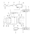
図1の車軸軸受メンテナンスシステムの概念構成を示す機能ブロック図である。
図1の車軸軸受メンテナンスシステムにおけるメンテナンスデータ管理手段における管理内容の例を示す説明図である。
図1の車軸軸受メンテナンスシステムの管理対象となる車軸軸受における各部の寸法の設計値と管理基準値とを比較して示す説明図である。
図1の車軸軸受メンテナンスシステムによる管理対象となる車輪用軸受の一例の部分は破断正面図である。
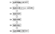
図1の車軸軸受メンテナンスシステムによるメンテナンス過程の説明図である。
この発明の一実施形態を図面と共に説明する。この車軸軸受メンテナンスシステムは、鉄道車両の車軸軸受6のメンテナンスデータを取得して管理し、車軸軸受6の劣化を判定する装置であって、測定機器1と、通信・情報処理端末(通信および情報処理のための端末)3と、コンピュータ8とを備える。
車軸軸受6は、例えば図5に示すように、複列外輪21、各列の内輪22,23、内輪間座24、各列の転動体33および保持器34、両側のオイルシール25,26、後蓋27、油切り28、前蓋29、締付ボルト30、座金31、ベント32等により構成される。
鉄道車両は定期的なメンテナンスが実施される。鉄道車両はメンテナンス工場に入場すると車体と台車に分解され、さらに搭載機器ごとに細かく分解される。このとき、車軸軸受6は、例えば図1に示すように、複列外輪21、各列の内輪22,23と保持器34および転動体33のアセンブリ部品、内輪間座24、後蓋27、油切り28、および前蓋29に分解される。
測定機器1は、前記車軸軸受6を、図1のように分解した状態、または組み立て状態で測定する機器であり、例えば、ダイヤルゲージ、マイクロメータ、シリンダーゲージ、圧力計、または重量計である。測定機器1は、1台または複数台であるが、図1では1台の場合を示している。測定機器1は、無線通信機2と接続されるか、または無線通信機2を備え、測定データであるメンテナンスデータを無線通信機2を介して送信する。無線通信機2は、送信専用であっても、またコマンドの受信等に応答してメンテナンスデータを送信する送受信可能なものであってもよい。
測定機器1により送信されたメンテナンスデータは、通信・情報処理端末3が備える無線通信機からなるデータ受信手段4により受信される。これら測定機器1の無線通信機2と通信・情報処理端末3のデータ受信手段4は、微弱電波で通信を行う近距離通信用であってもよい。
通信・情報処理端末3は、通信機能および情報処理機能を有する可搬で汎用の情報処理装置であり、例えば、タブレット型端末、または所謂スマートフォン等の携帯電話である。通信・情報処理端末3は、図2に示すように、アプリケーションソフトウェアを使用者が任意にイントール可能なオペレーションシステム(OS)11を備え、また液晶表示装置等の画像表示装置3a、カメラ13、およびデータ送信手段16を有する。通信・情報処理端末3は、さらに、標準装備となるアプリケーションソフトウェアで構成される画像判別手段14と、追加のアプリケーションソフトウェアであるメンテナンスデータ管理ソフトウェア5(図1参照)からアクセスされるメンテナンスデータ管理手段15と、データ表示手段17とを有する。通信・情報処理端末3は、前記画像表示装置3aの画面上に実現されるタッチパネルまたは物理的に存在するキースイッチ等の入力操作手段(図示せず)を有している。
前記画像判別手段14は、カメラ13で撮像した画像から車軸軸受6の識別情報を判別する手段である。車軸軸受6の識別情報は、例えば車軸軸受6に個別に割り当てられる製造番号等のシリアルナンバーであり、車軸軸受6に付された識別情報記録手段7に二次元コード等によって表示される。識別情報記録手段7は、車軸軸受6に1ヵ所のみに設けられていても、また異なる軸受構成部品に設ける等、複数箇所に設けられていてもよい。前記カメラ13と前記画像判別手段14とで、識別情報読取手段12が構成される。前記識別情報記録手段7は、二次元バーコードの代わりに、1次元バーコードや無線ICタグ等であってもよい。ただし、通信・情報処理端末3に標準装備されている画像判別手段14が利用できる点で、二次元バーコードが好ましい。前記識別情報読取手段12は、前記識別情報記録手段7が無線ICタグである場合は、タグリーダとされる。
前記メンテナンスデータ管理手段15は、前記データ受信手段4で受信したメンテナンスデータと前記識別情報読取手段12で読み取った車軸軸受6の識別情報とを関連付けて記憶する手段であり、データベースとして、またはメモリ等に記憶される表等として構成される。メンテナンスデータ管理手段15は、例えば、図3に示すように、一つの識別情報に対して、各部の寸法A~C、重量A、圧力A等の各種のメンテナンスデータを記憶する。異なる測定機器1により測定したメンテナンスデータであっても、識別情報が同じであればその識別情報に関連付けて共に記憶する。
メンテナンスデータ管理手段15で管理する寸法に係るメンテナンスデータは、例えば図4に示すように、車軸軸受6の外径寸法、内径寸法、油切り28のシール摺動部の外径寸法、内径寸法、後蓋27のシール摺動部の外径寸法、内径寸法、輪軸におけるジャーナル部軸取り付け部寸法、ジャーナル部前蓋取り付け部寸法等を含む。前記メンテナンスデータは、さらに、各部の隙間寸法等を含んでもよい。メンテナンスデータ管理手段15は、メンテナンスデータと共に、対応する車軸軸受6の設計値や管理基準値等を記憶してもよい。
図2において、データ表示手段17は、メンテナンスデータ管理手段15に記録されているメンテナンスデータを画像表示装置3aの画面に表示する手段である。データ表示手段17は、メンテナンスデータの受信時にその受信したメンテナンスデータを表示してもよい。
データ送信手段16は、通信ネットワーク18を介してコンピュータ8と通信する手段であり、メンテナンスデータ管理手段15に記憶されているメンテナンスデータ等を送信する。通信ネットワーク18は、ローカルエリアネットワークであっても、インターネット等を利用する広域ネットワークであってもよい。代わりに、単に通信・情報処理端末3と1台のコンピュータ8とを接続する配線であってもよい。さらに代わりに、USBなどの記憶媒体に保存してデータを移す方法でもよい。
コンピュータ8は、メンテナンスデータ分析手段41、通信装置42、およびメンテナンスデータ記憶部43を有している。コンピュータ8は、例えばサーバ機であり、物理的に一つのコンピュータであっても、またクラウド技術等を用いた複数のコンピュータにより概念的に一つのコンピュータとなるものであってもよい。通信装置42は、前記ネットワーク18を介して通信を行う手段である。通信装置42で受信したメンテナンスデータ等は、メンテナンスデータ記憶部43に記憶しておく。
前記メンテナンスデータ分析手段41は、前記通信・情報処理端末3から送信されて受信した前記車軸軸受6の識別情報とメンテナンスデータとから、前記メンテナンスデータを分析する手段である。前記メンテナンスデータ分析手段41は、メンテナンスデータに所定の分析を行う分析部41aと、その分析結果を表示する分析結果表示部41b、分析用の軸受諸元や基準値等を記憶したデータ記憶部41cを有している。
前記分析用の軸受諸元や基準値等は、コンピュータ8自体が記憶していてもよく、また他のコンピュータ(図示せず)に記憶されていて、コンピュータ8と通信ネットワーク18等を介して読み出すようにしてもよい。このコンピュータ8や他のコンピュータに記憶されている分析用の軸受諸元や基準値等は、車軸軸受6の識別情報と関連付けられており、その読み出しに、前記メンテナンスデータと共に送信された識別情報が用いられる。
この構成の車軸軸受メンテナンスシステムの使用方法および軸受メンテナンスについて説明する。図6は、メンテナンス作業の流れを示す。
ステップS1:車軸軸受6を輪軸35から取り外す。
ステップS2:車軸軸受6を分解する。この分解は、図1と共に前述したように行い、またオイルシール25,26を分解する。
ステップS3:車軸軸受6の分解した各構成部品を洗浄する。
ステップS4:車軸軸受6の検査を行う。この検査では、車軸軸受6の図1のように分解された各構成部品の定められた箇所の寸法等を前記測定機器1であるマイクロメータまたはシリンダーゲージ等により測定し、測定値が管理基準値内に収まっているか否かを確認する。検査箇所は、例えば図4と共に前述した各部の寸法である。また、目視による外観検査等を行う。
ステップS5:車軸軸受6を、分解された部品を用いて組み立てる。オイルシール25,26など、消耗している部品については、新品と交換して組み立ててもよい。組み立てられた車軸軸受6には、グリースを封入する。このとき、車軸軸受6の重量を、測定機器1の一つである重量計等により測定し、グリース封入量を確認して封入量の調整を行う。
ステップS6:組み立てられた車軸軸受6を、輪軸35に取付ける。このとき、組み立てられた車軸軸受6のアキシャルスキマ等を前記測定機器1の一つであるダイヤルゲージ等で測定する。後蓋27と輪軸35の段差面ついては、押増ししたときの押増し力を前記測定機器1の一つである圧力計で測定する。
このようにして一連のメンテナンス作業を行う。
ステップS1:車軸軸受6を輪軸35から取り外す。
ステップS2:車軸軸受6を分解する。この分解は、図1と共に前述したように行い、またオイルシール25,26を分解する。
ステップS3:車軸軸受6の分解した各構成部品を洗浄する。
ステップS4:車軸軸受6の検査を行う。この検査では、車軸軸受6の図1のように分解された各構成部品の定められた箇所の寸法等を前記測定機器1であるマイクロメータまたはシリンダーゲージ等により測定し、測定値が管理基準値内に収まっているか否かを確認する。検査箇所は、例えば図4と共に前述した各部の寸法である。また、目視による外観検査等を行う。
ステップS5:車軸軸受6を、分解された部品を用いて組み立てる。オイルシール25,26など、消耗している部品については、新品と交換して組み立ててもよい。組み立てられた車軸軸受6には、グリースを封入する。このとき、車軸軸受6の重量を、測定機器1の一つである重量計等により測定し、グリース封入量を確認して封入量の調整を行う。
ステップS6:組み立てられた車軸軸受6を、輪軸35に取付ける。このとき、組み立てられた車軸軸受6のアキシャルスキマ等を前記測定機器1の一つであるダイヤルゲージ等で測定する。後蓋27と輪軸35の段差面ついては、押増ししたときの押増し力を前記測定機器1の一つである圧力計で測定する。
このようにして一連のメンテナンス作業を行う。
前記検査のステップS4、組み立てのステップS5、および輪軸35への取付けのステップS6で得られた、各測定機器1による測定値であるメンテナンスデータは、測定対象部品1から通信・情報処理端末3に無線で送信されて、測定機器1のメンテナンスデータ管理手段15で管理される。測定に際しては、先に車軸軸受6の識別情報記録手段7に二次元コードで表示されている車軸軸受6のシリアナンバー等の識別情報を、通信・情報処理端末3のカメラ13で撮影し、画像から画像判別手段14により識別情報を識別しておく。これにより、メンテナンスデータ管理手段15は、識別情報とメンテナンスデータとを関連付けて各測定機器1の測定値を管理する。メンテナンス時の目視による調査結果は、メンテナンスデータ管理手段15に、手入力で入力されてもよい。
メンテナンスデータ管理手段15で管理されているメンテナンスデータは、通信・情報処理端末3有する操作手段(図示せず)が操作されると、データ表示手段17により、通信・情報処理端末3の液晶表示装置等の画像表示装置3aに表示される。
また、メンテナンスデータ管理手段15で管理されているメンテナンスデータは、データ送信手段16により、識別情報と共にコンピュータ8に送信される。コンピュータ8は、受信したメンテナンスデータをメンテナンスデータ記憶部43に記憶しておき、メンテナンスデータ分析手段41の分析部41aで所定の分析を行い、その分析結果を分析結果表示部41bで表示して、作業者が車軸軸受6の劣化の程度の判別や、軸受交換時期を予測する。または、メンテナンスデータ分析手段41の分析部41aで、その分析結果から所定の判断基準で車軸軸受6の劣化状態を判別してもよい。この判別や分析には、車軸軸受6についての軸受諸元や管理基準値等が必要であり、これら軸受諸元や管理基準値等は、メンテナンスデータ分析手段41の判別・分析用データ記憶部41cに記憶しておくか、または他のコンピュータ等のデータベース(図示せず)に車軸軸受6を型番毎に登録されている軸受諸元や管理基準値等をメンテナンスデータ分析手段41により前記識別情報を用いてアクセスして取得し、分析用データ記憶部41cに記憶して、用いられる。
メンテナンスデータ分析手段41による分析結果や劣化判定結果については、作業者がコンピュータ8の有する画像表示装置(図示せず)を直接して見て把握してもよい。代わりに、コンピュータ8の所定の記憶領域(図示せず)に記憶しておき、前記通信・情報処理端末3や他の表示用の端末(図示せず)を介してアクセスされてもよい。ただし、通信・情報処理端末3からの分析要求に対する応答として表示されるのが好ましい。このようにして、作業者が車軸軸受6の劣化状態を把握することができる。
この構成によると、測定機器1で測定されたメンテナンスデータは、無線により通信・情報処理端末3に送信されることで、この通信・情報処理端末3が有するメンテナンスデータ管理手段15に入力される。このとき、メンテナンスデータ管理手段15は、通信・情報処理端末3が有する識別情報読取手段12で読み取った車軸軸受6の識別情報に、メンテナンスデータを関連付けて記憶する。また、通信・情報処理端末3は、この管理されているメンテナンスデータをコンピュータ8に送信し、前記コンピュータ8は送信されたメンテナンスデータを分析し前記車軸軸受6の劣化状態を表示する。
このため、メンテナンスデータの手作業による入力を行うことなく、メンテナンスデータの入力から、管理、およびメンテナンスデータの分析による車軸軸受6の劣化状態の確認が行え、メンテナンス作業の高効率化と記録の誤りを防止することができる。
また、メンテナンスデータと車軸軸受6の識別情報とを関連付けた一元管理によりトレーサビリティを確保でき、さらに車軸軸受6の劣化状態を確認することにより軸受交換時期の予測に利用可能となる。
前記測定機器1で測定したメンテナンスデータの管理およびコンピュータ8への送信は、アプリケーションプログラムがインストール可能な汎用の通信・情報処理端末3を用いて行うため、専用機器を製作して用いる場合と異なり、安価に車軸軸受メンテナンスシステムを構築できる。また、前記通信・情報処理端末3は可搬であり、かつ識別情報読取手段12を有するため、測定対象の車軸軸受6に近づけてその識別情報記録手段7を読み取ることができる。そのため、識別情報の読み取りが行い易く、前記測定機器1と通信・情報処理端末3の無線通信に近距離用の弱い電波を用いることができる。
前記通信・情報処理端末3が前記データ表示手段17を有すると、作業者によるメンテナンスデータの確認が容易に行える。また、前記通信・情報処理端末3がタブレット型端末機であると、携帯に便利であるうえ、画像表示装置3aの画面がある程度大きく、メンテナンスデータを読み易く表示することができる。前記識別情報記録手段7が二次元コードであると、汎用の通信・情報処理端末が一般的に有するカメラおよび画像判別手段を識別情報読取手段12として利用することができるうえ、情報の表示量が多く、多数桁のシリアルナンバー等の識別情報を表すことができる。このように、二次元コードおよびカメラ付きのタブレット型端末機を利用することで、この車軸軸受メンテナンスシステムを、安価でかつ使用に便利のものとすることができる。
この車軸軸受メンテナンスシステムによると、このようにメンテナンスデータの手書き記録を省略することで、メンテナンス作業の高効率化と記録の誤りを防止することができる。また、メンテナンスデータの車両情報や軸受識別番号と関連付けた一元管理により、トレーサビリティを確保できる。車軸軸受6の劣化状態を容易に把握することで、メンテナンスの信頼性向上と交換時期の予測が可能となる。
以上のとおり、図面を参照しながら好適な実施形態を説明したが、本発明の趣旨を逸脱しない範囲内で、種々の追加、変更または削除が可能である。したがって、そのようなものも本発明の範囲内に含まれる。
1…測定機器
2…無線通信機
3…通信・情報処理端末
4…データ受信手段
6…車軸軸受
8…コンピュータ
15…メンテナンスデータ管理手段
16…データ送信手段
41…メンテナンスデータ分析手段
2…無線通信機
3…通信・情報処理端末
4…データ受信手段
6…車軸軸受
8…コンピュータ
15…メンテナンスデータ管理手段
16…データ送信手段
41…メンテナンスデータ分析手段
Claims (4)
- 鉄道車両の車軸軸受のメンテナンスデータの管理および分析を行うメンテナンスシステムであって、
少なくとも一つの測定機器であって、それぞれ、測定対象の車軸軸受を測定して測定値を取得し、無線通信機を介して前記測定値を送信する、少なくとも一つの測定機器と、
可搬でアプリケーションプログラムがインストール可能な汎用の通信・情報処理端末と、
通信機能を有するデータ分析用のコンピュータとを備え、
前記通信・情報処理端末が、
前記少なくとも一つの測定機器から、前記無線通信機を介して前記測定値を受信するデータ受信手段と、
測定対象の車軸軸受に関連付けられた識別情報記録手段の識別情報を読み取る識別情報読取手段と、
前記データ受信手段で受信した前記測定値をメンテナンスデータとし、このメンテナンスデータと、前記識別情報読取手段で読み取った車軸軸受の識別情報とを関連付けて記憶するメンテナンスデータ管理手段と、
このメンテナンスデータ管理手段に記憶されているメンテナンスデータおよび識別情報を前記コンピュータに送信するデータ送信手段とを有し、
前記コンピュータが、
前記通信・情報処理端末から送信された前記車軸軸受の前記識別情報と前記メンテナンスデータとから前記メンテナンスデータを分析し前記車軸軸受の劣化状態を表示するメンテナンスデータ分析手段を有する、車軸軸受メンテナンスシステム。 - 請求項1に記載の車軸軸受メンテナンスシステムにおいて、前記通信・情報処理端末がタブレット型端末機であり、前記識別情報記録手段が二次元コードであり、前記識別情報読取手段がカメラとこのカメラで撮像された二次元コードから前記識別情報を判別する画像判別手段であり、前記通信・情報処理端末が、さらに、前記メンテナンスデータを画像表示装置の画面に表示させるデータ表示手段を有する、車軸軸受メンテナンスシステム。
- 請求項1または請求項2に記載の車軸軸受メンテナンスシステムにおいて、前記少なくとも一つの測定機器が、ダイヤルゲージ、マイクロメータ、シリンダーゲージ、ノギス、ハイトゲージ、デプスゲージ、圧力計、および重量計のうちの少なくとも一つ含む、車軸軸受メンテナンスシステム。
- 請求項1ないし請求項3のいずれか1項に記載の車軸軸受メンテナンスシステムにおいて、前記少なくとも一つの測定機器が、メンテナンス時の複数の測定工程ごとの複数種の測定機器を含み、前記通信・情報処理端末の前記メンテナンスデータ管理手段が、前記複数種の測定機器で測定したメンテナンスデータを管理する、車軸軸受メンテナンスシステム。
Priority Applications (1)
| Application Number | Priority Date | Filing Date | Title |
|---|---|---|---|
| PH12019500821A PH12019500821A1 (en) | 2016-10-19 | 2019-04-15 | Axle bearing maintenance system |
Applications Claiming Priority (2)
| Application Number | Priority Date | Filing Date | Title |
|---|---|---|---|
| JP2016205135A JP2018066644A (ja) | 2016-10-19 | 2016-10-19 | 車軸軸受メンテナンスシステム |
| JP2016-205135 | 2016-10-19 |
Publications (1)
| Publication Number | Publication Date |
|---|---|
| WO2018074472A1 true WO2018074472A1 (ja) | 2018-04-26 |
Family
ID=62018737
Family Applications (1)
| Application Number | Title | Priority Date | Filing Date |
|---|---|---|---|
| PCT/JP2017/037535 Ceased WO2018074472A1 (ja) | 2016-10-19 | 2017-10-17 | 車軸軸受メンテナンスシステム |
Country Status (3)
| Country | Link |
|---|---|
| JP (1) | JP2018066644A (ja) |
| PH (1) | PH12019500821A1 (ja) |
| WO (1) | WO2018074472A1 (ja) |
Cited By (2)
| Publication number | Priority date | Publication date | Assignee | Title |
|---|---|---|---|---|
| CN110362883A (zh) * | 2019-06-25 | 2019-10-22 | 中车青岛四方机车车辆股份有限公司 | 一种检修组装工艺设计方法及转向架检修组装方法 |
| WO2026011231A1 (en) * | 2024-07-10 | 2026-01-15 | Lubtrack Ltda | Lubrication management system |
Families Citing this family (1)
| Publication number | Priority date | Publication date | Assignee | Title |
|---|---|---|---|---|
| CN117782647B (zh) * | 2024-02-23 | 2024-06-04 | 杭州中港地铁装备维护有限公司 | 一种地铁行走部轴承健康状态监测系统 |
Citations (6)
| Publication number | Priority date | Publication date | Assignee | Title |
|---|---|---|---|---|
| JPH0249117A (ja) * | 1988-05-20 | 1990-02-19 | Man Design Kk | 携帯型データ送受信装置 |
| JP2005308005A (ja) * | 2004-04-16 | 2005-11-04 | Ntn Corp | Icタグ付き軸受ユニット |
| JP2008085076A (ja) * | 2006-09-27 | 2008-04-10 | Juki Corp | 部品実装機のメンテナンス情報管理装置 |
| JP2012203418A (ja) * | 2011-03-23 | 2012-10-22 | Ntn Corp | 機械要素部品の余寿命算出方法 |
| US20140259719A1 (en) * | 2013-03-15 | 2014-09-18 | Bosch Automotive Service Solutions Llc | Combination Gauge Tool |
| JP2014174684A (ja) * | 2013-03-07 | 2014-09-22 | Ihi Corp | メンテナンス支援システム及び方法 |
Family Cites Families (3)
| Publication number | Priority date | Publication date | Assignee | Title |
|---|---|---|---|---|
| JP2013037619A (ja) * | 2011-08-10 | 2013-02-21 | Sumitomo (Shi) Construction Machinery Co Ltd | 建設機械における情報管理システム、制御装置、携帯端末、及び表示制御方法 |
| JP2013218559A (ja) * | 2012-04-10 | 2013-10-24 | Mitsubishi Electric Corp | 空調機管理装置、空調機管理プログラム、及び空調機管理システム |
| JP6475029B2 (ja) * | 2015-01-29 | 2019-02-27 | 清水建設株式会社 | 構造物点検支援システム |
-
2016
- 2016-10-19 JP JP2016205135A patent/JP2018066644A/ja active Pending
-
2017
- 2017-10-17 WO PCT/JP2017/037535 patent/WO2018074472A1/ja not_active Ceased
-
2019
- 2019-04-15 PH PH12019500821A patent/PH12019500821A1/en unknown
Patent Citations (6)
| Publication number | Priority date | Publication date | Assignee | Title |
|---|---|---|---|---|
| JPH0249117A (ja) * | 1988-05-20 | 1990-02-19 | Man Design Kk | 携帯型データ送受信装置 |
| JP2005308005A (ja) * | 2004-04-16 | 2005-11-04 | Ntn Corp | Icタグ付き軸受ユニット |
| JP2008085076A (ja) * | 2006-09-27 | 2008-04-10 | Juki Corp | 部品実装機のメンテナンス情報管理装置 |
| JP2012203418A (ja) * | 2011-03-23 | 2012-10-22 | Ntn Corp | 機械要素部品の余寿命算出方法 |
| JP2014174684A (ja) * | 2013-03-07 | 2014-09-22 | Ihi Corp | メンテナンス支援システム及び方法 |
| US20140259719A1 (en) * | 2013-03-15 | 2014-09-18 | Bosch Automotive Service Solutions Llc | Combination Gauge Tool |
Cited By (2)
| Publication number | Priority date | Publication date | Assignee | Title |
|---|---|---|---|---|
| CN110362883A (zh) * | 2019-06-25 | 2019-10-22 | 中车青岛四方机车车辆股份有限公司 | 一种检修组装工艺设计方法及转向架检修组装方法 |
| WO2026011231A1 (en) * | 2024-07-10 | 2026-01-15 | Lubtrack Ltda | Lubrication management system |
Also Published As
| Publication number | Publication date |
|---|---|
| JP2018066644A (ja) | 2018-04-26 |
| PH12019500821A1 (en) | 2020-01-20 |
Similar Documents
| Publication | Publication Date | Title |
|---|---|---|
| KR101781337B1 (ko) | 생산공정 데이터 관리 시스템 | |
| CN104335024A (zh) | 轴承监控方法和系统 | |
| US11003178B2 (en) | Facility diagnosis device, facility diagnosis method, and facility diagnosis program | |
| US20190050752A1 (en) | Algorithm and method for detecting error data of machine based on machine-learning technique | |
| CN105164736B (zh) | 便捷式数据收集系统和方法 | |
| KR20180006893A (ko) | 통합 자산 완전성 관리 시스템 | |
| WO2013146502A1 (ja) | 鉄道車両用軸受の異常検知システム | |
| CN104764595B (zh) | 远程诊断系统 | |
| JP2016535885A (ja) | 資産監視用の汎用無線プラットフォームのための方法およびシステム | |
| JP6849626B2 (ja) | 携帯端末を用いた設備点検システム及び設備点検方法 | |
| JP2016529630A (ja) | 検出システム | |
| JP2013257265A (ja) | 鉄道車両用軸受の異常検知システム | |
| KR102238059B1 (ko) | 동적 워크플로우 우선순위 선정 및 작업 수행을 위한 방법들 및 시스템들 | |
| WO2018074472A1 (ja) | 車軸軸受メンテナンスシステム | |
| CN105829857A (zh) | 旋转机械部件的利用便携终端的检查系统和检查方法 | |
| US10094729B2 (en) | System, method, and apparatus for certifying a brake pressure calibration for an end-of-train device | |
| CN106996865A (zh) | 贴纸、状况监测系统、方法和计算机程序产品 | |
| JP2006085573A (ja) | 設備機器の保守管理システム | |
| WO2016009883A1 (ja) | 携帯端末利用検査システムおよびそのサーバ | |
| US10379982B2 (en) | Computer system and method for performing a virtual load test | |
| KR20110019938A (ko) | 센서태그를 이용한 바이오/의료장비 이상 이력관리 시스템 및 그 운용방법 | |
| US20160170395A1 (en) | Case management linkage of updates, evidence, and triggers | |
| KR101387968B1 (ko) | 상태분석 룰 기반 플랜트 필드 데이터 상태분석 방법 | |
| CN112414473A (zh) | 一种对设备进行点检的方法及点检系统 | |
| JP7657128B2 (ja) | 点検ルート計画提案システム |
Legal Events
| Date | Code | Title | Description |
|---|---|---|---|
| 121 | Ep: the epo has been informed by wipo that ep was designated in this application |
Ref document number: 17861462 Country of ref document: EP Kind code of ref document: A1 |
|
| NENP | Non-entry into the national phase |
Ref country code: DE |
|
| 122 | Ep: pct application non-entry in european phase |
Ref document number: 17861462 Country of ref document: EP Kind code of ref document: A1 |