WO2018074450A1 - 電子線照射装置 - Google Patents
電子線照射装置 Download PDFInfo
- Publication number
- WO2018074450A1 WO2018074450A1 PCT/JP2017/037470 JP2017037470W WO2018074450A1 WO 2018074450 A1 WO2018074450 A1 WO 2018074450A1 JP 2017037470 W JP2017037470 W JP 2017037470W WO 2018074450 A1 WO2018074450 A1 WO 2018074450A1
- Authority
- WO
- WIPO (PCT)
- Prior art keywords
- electron beam
- connector
- terminal
- vacuum chamber
- beam irradiation
- Prior art date
- Legal status (The legal status is an assumption and is not a legal conclusion. Google has not performed a legal analysis and makes no representation as to the accuracy of the status listed.)
- Ceased
Links
Images


Classifications
-
- G—PHYSICS
- G21—NUCLEAR PHYSICS; NUCLEAR ENGINEERING
- G21K—HANDLING OF PARTICLES OR IONISING RADIATION NOT OTHERWISE PROVIDED FOR; IRRADIATION DEVICES; GAMMA RAY OR X-RAY MICROSCOPES
- G21K5/00—Irradiation devices
-
- G—PHYSICS
- G21—NUCLEAR PHYSICS; NUCLEAR ENGINEERING
- G21K—HANDLING OF PARTICLES OR IONISING RADIATION NOT OTHERWISE PROVIDED FOR; IRRADIATION DEVICES; GAMMA RAY OR X-RAY MICROSCOPES
- G21K5/00—Irradiation devices
- G21K5/04—Irradiation devices with beam-forming means
Definitions
- the present invention relates to an electron beam irradiation apparatus.
- an electron beam irradiation apparatus used for curing of coating agents, printing inks, adhesives and the like, sterilization of packaging materials and containers for food and medicine, and the like are known (see, for example, Patent Document 1).
- Such an electron beam irradiation apparatus includes a vacuum chamber, a terminal incorporated in the vacuum chamber to generate an electron beam, and a filament incorporated in the terminal to generate thermal electrons. Then, the electron beam irradiation apparatus accelerates the electron beam generated at the terminal at a high voltage in the vacuum chamber to irradiate the object to be irradiated.
- a high voltage ceramic insulator is used to insulate between the vacuum chamber and the insulation chamber provided with the high voltage connection receptacle joined to the high voltage power cable connector. There is. Furthermore, the insulating chamber provided with the high voltage connection receptacle is filled with a gas or liquid insulating medium to insulate the high voltage connection receptacle.
- the insulating chamber provided with the high voltage connection receptacle and the vacuum chamber are insulated with high voltage insulator, and the insulating chamber is filled with the insulating medium to insulate the high voltage connection receptacle.
- the device configuration is complicated, which causes the device to be large.
- high effects can be efficiently obtained.
- the required radiation dose can be finely set depending on the type and composition of the coating agent, so that only the coating layer can be sufficiently cured while suppressing deterioration of the base substrate.
- high effects can be efficiently obtained, and therefore, application to various fields of the electron beam irradiation device is expected, and there is a strong demand for downsizing and weight reduction of the device.
- the present invention has been made in view of the above-described circumstances, and an object of the present invention is to provide an electron beam irradiation apparatus which is reduced in size and weight.
- the present invention includes an electron beam generating unit that generates an electron beam, and the electron beam generating unit passes through a filament that generates thermoelectrons, and thermions generated by the filament pass through.
- a terminal having a diffusion plate, and a vacuum chamber for accelerating the thermal electrons in a vacuum space, and the vacuum chamber is provided with an electron beam extraction window for emitting an electron beam generated in the electron beam generation unit.
- the connector is directly connected to the terminal, into which a high voltage cable is inserted.
- the connector is formed of a material excellent in insulation and flame retardancy, and has a function of electrically separating a high voltage power source and the vacuum chamber, and the connector And a function to insulate the receptacle of the unit.
- the electron beam generation unit is cylindrical, the central axis is disposed substantially horizontally, and the connector is from the side orthogonal to the radiation direction of the electron beam. It is characterized in that it is directly connected to the terminal.
- the electron beam generation unit is cylindrical, the central axis is disposed substantially horizontally, and the connector is directly connected to the terminal in parallel with the radiation direction of the electron beam. It is characterized by being.
- the connector is formed such that the receptacle is formed by denting one end facing the outside of the electron beam generation unit, and the other end is directly connected to the terminal. It features.
- the terminal is directly connected to the connector into which the high voltage cable is inserted, there is no need to provide an insulation chamber and fill the insulation chamber with an insulation material such as an insulation gas.
- the size and weight of the electron beam irradiation apparatus can be reduced.
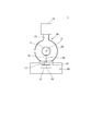
- FIG. 1 is a side cross-sectional view showing a schematic configuration of an electron beam irradiation apparatus according to an embodiment of the present invention.
- FIG. 2 is a front sectional view showing a schematic configuration of the electron beam irradiation apparatus.
- FIG. 3 is a perspective view showing a connector and a receptacle.
- FIG. 4 is a side sectional view showing a schematic configuration of an electron beam irradiation apparatus according to another embodiment of the present invention.
- FIG. 5 is a front sectional view showing a schematic configuration of the electron beam irradiation apparatus.
- FIG. 1 is a side cross-sectional view showing a schematic configuration of an electron beam irradiation apparatus 1 according to the present embodiment.
- FIG. 2 is a front sectional view of the electron beam irradiation apparatus 1.
- the electron beam irradiation apparatus 1 is an apparatus that generates an electron beam, accelerates the generated electron beam, and irradiates the irradiation target X with the electron beam.
- the electron beam irradiation apparatus 1 can be suitably used in applications such as curing of a coating film by electron beam irradiation, crosslinking and modification of rubber and resin, graft polymerization of rubber and resin, sterilization of packaging material and container, etc. it can.
- the electron beam irradiation apparatus 1 includes an electron beam generator 10 that generates an electron beam 80, and arranges the electron beam 80 generated by the electron beam generator 10 in the irradiation space 50. It is comprised so that the irradiated object X may be irradiated.
- the electron beam generator 10 includes a terminal 11 and a vacuum chamber 20.
- the terminal 11 includes a linear filament 13 emitting thermoelectrons, a housing 14 supporting the filament 13 inside, and a diffusion plate 15.
- the vacuum chamber 20 includes a cylindrical cylindrical casing 25 arranged so that its central axis O is substantially horizontal, and end caps 21A and 21B for closing the openings at both ends of the cylindrical casing 25. There is.
- the housing 14 of the terminal 11 is formed in a cylindrical shape extending along the central axis O of the vacuum chamber 20.
- the terminal 11 is desirably provided concentrically with the central axis O of the vacuum chamber 20.
- the housing 14 has an opening 14A extending longitudinally in the side of the cylinder.
- the diffusion plate 15 is provided to cover the opening 14A.
- the diffusion plate 15 has a plurality of openings arranged in a grid shape (not shown).
- the diffusion plate 15 has a function of adjusting the flow of electrons, and among the thermions generated by the filament 13, thermions having passed through the diffusion plate 15 are emitted into the vacuum chamber 20.
- An evacuation system 19 is connected to the vacuum chamber 20.
- the vacuum evacuation system 19 is connected to the internal space of the cylindrical casing 25 by an exhaust pipe 23 provided on the cylindrical side surface of the cylindrical casing 25.
- the inside of the vacuum chamber 20 is evacuated by the evacuation system 19 so as to be a high vacuum state, which is 3 ⁇ 10 ⁇ 3 or less in the present embodiment.
- the evacuation system 19 is equipped with a vacuum device such as a vacuum pump although not shown.
- thermoelectrons emitted from the terminal 11 into the vacuum chamber 20 are accelerated by a high voltage applied through a high voltage cable 30 described later to form an electron beam 80.
- an electron beam extraction window 16 for extracting the electron beam 80 generated by the electron beam generator 10 into the irradiation space 50 is provided.
- the electron beam extraction window 16 extends a predetermined length along the central axis O of the vacuum chamber 20 and has a predetermined width corresponding to the irradiated region.
- the electron beam extraction window 16 includes a window frame 17 attached to the bottom of the vacuum chamber 20, and a metal foil 18 closing the opening 17A of the window frame 17 and sealing the vacuum chamber 20.
- the metal foil 18 is made of a foil of titanium, magnesium, aluminum, beryllium or the like.
- the electron beam extraction window 16 is sealed with a metal foil 18 so as to maintain a vacuum in the vacuum chamber 20.
- the metal foil 18 has a specific gravity that allows the electron beam 80 to easily penetrate, and is excellent in heat resistance such that the electron beam 80 transmitted through the metal foil 18 is irradiated to the irradiated object X disposed in the irradiation space 50.
- the structure is
- a through hole 22 is provided concentrically with the central axis O of the vacuum chamber 20.
- the connector 40 is inserted into the through hole 22.
- the connector 40 is made of a resin that is integrally formed in its entirety.
- the connector 40 includes a large diameter portion 41 and a small diameter portion 42.
- the connector 40 is inserted into the vacuum chamber 20 through the through hole 22, the small diameter portion 42 is disposed inside the vacuum chamber 20, and the large diameter portion 41 is disposed outside the vacuum chamber 20.
- the connector 40 is integrally provided with a flange portion 45 at the boundary between the large diameter portion 41 and the small diameter portion 42.
- the connector 40 is configured such that the flange portion 45 is fastened and fixed to the outside of one end cap 21A and the vacuum chamber 20 is sealed.
- FIG. 3 is a view showing the configuration of the connector 40 and the high voltage cable 30.
- the connector 40 as shown in FIG. 3, is provided with a receptacle 47 formed in a recess at one end 40A of the vacuum chamber 20.
- the high voltage cable 30 extends from a high voltage power supply (not shown) and has a power plug 31 at its tip. The power supply plug 31 of the high voltage cable 30 is inserted into the receptacle 47 of the connector 40 so that the high voltage cable 30 and the connector 40 are electrically connected to apply a voltage to the electron beam irradiation apparatus 1.
- the electron beam irradiation apparatus 1 is an apparatus for generating the electron beam 80 at an acceleration voltage of a relatively low voltage of 40 kV to 150 kV applied through the high voltage cable 30.
- the electron beam irradiation apparatus 1 is preferably used at an acceleration voltage as low as 100 kV or less, more preferably 90 kV or less.
- the connector 40 is formed of an insulating resin material having a high flame retardancy grade.
- an insulating resin material of grade UL 94 V-0 can be suitably used.
- the connector 40 is not limited to the insulating resin material, and may be formed of a flame retardant member such as ceramic.
- the receptacle 47 extends along the central axis O of the vacuum chamber 20 from the large diameter portion 41 of the connector 40 to the middle of the small diameter portion 42.
- power supply lines 48A and 48B are wired from the receptacle 47 through the resin inside of the small diameter portion 42.
- the connector 40 is fixed to the vacuum chamber 20, and the power supply line 48A leading from the other end 40B disposed inside the vacuum chamber 20 is electrically and mechanically connected to the terminal 11 It is done. Further, the other power supply line 48 B extending from the other end 40 B of the connector 40 is connected to one end of the filament 13, and the other end of the filament 13 is connected to the terminal 11. That is, electrically, one power supply line 48A of the connector 40 is connected to the terminal 11, the terminal 11 to the filament 13, and the filament 13 to the other power supply line 48B. Although illustration is omitted, the power supply lines 48A and 48B are metal rods and are connected to the terminals by the taps cut at the tip. Thus, the connector 40 is configured such that the power supply lines 48A and 48B wired through the resin inside of the connector 40 are directly connected to the terminal.
- the connector 40 having the receptacle 47 into which the power plug 31 of the high voltage cable 30 is inserted is directly connected to the terminal 11. Since the connector 40 is made of resin, the high voltage cable 30 and the power plug 31 can be electrically separated from the vacuum chamber 20, and the terminal 11 and the vacuum chamber 20 are electrically separated. Can.
- the electron beam generation unit 10 that generates the electron beam 80 is provided, and the electron beam generation unit 10 includes the filament 13 that generates thermal electrons and the heat generated by the filament 13
- the electron beam includes a terminal 11 having a diffusion plate 15 through which electrons pass, and a vacuum chamber 20 that accelerates the thermoelectrons in a vacuum space, and the vacuum chamber 20 emits electrons generated by the electron beam generator 10
- a line extraction window 16 is provided, and a connector 40 into which the high voltage cable 30 is inserted is directly connected to the terminal 11.
- the electron beam irradiation apparatus 1 can be made smaller and lighter.
- SF6 gas generally used as an insulating material has a high environmental load, it is not necessary to use the insulating material in the present embodiment, which can contribute to the reduction of the environmental load.
- the connector 40 is formed of a material excellent in insulation and flame resistance, and has a function of electrically separating the high voltage power supply and the vacuum chamber 20, and the receptacle 47 of the connector 40. Integrally equipped with the function to achieve insulation. According to this configuration, the size and weight of the electron beam irradiation apparatus 1 can be reduced.
- the electron beam generator 10 has a cylindrical shape, the center axis O is disposed substantially horizontally, and the connector 40 is connected to the terminal 11 from the side orthogonal to the radiation direction of the electron beam 80. Directly connected. According to this configuration, the connector 40 can be directly connected to the terminal 11 without affecting the radiation of the electron beam 80. In addition, since the connector 40 can be directly connected to the terminal 11 without providing an insulating chamber for filling and sealing the insulating material, the volume of the device can be made much smaller than before.
- the connector 40 has one end 40A facing the outside of the electron beam generator 10 recessed to form a receptacle 47, and the other end 40B is directly connected to the terminal 11. According to this configuration, it is possible to easily electrically isolate the high voltage power supply and the vacuum chamber 20 and to achieve insulation of the connector 40 by using, for example, the connector 40 integrally formed of a resin material. Therefore, the structure of the electron beam irradiation apparatus 1 can be simplified, and the miniaturization and weight reduction of the electron beam irradiation apparatus 1 can be achieved.
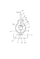
- FIG. 4 is a side sectional view showing a schematic configuration of an electron beam irradiation apparatus 100 according to another embodiment of the present invention.
- FIG. 5 is a front sectional view showing a schematic configuration of the electron beam irradiation apparatus 100.
- the connector 40 is inserted into the terminal 11 extending along the central axis O of the cylindrical vacuum chamber 20 through the through hole 22 provided in the end cap 21A of the vacuum chamber 20. It is a configuration that is directly connected.
- the vacuum chamber 200 is provided with the connector attaching part 130 to which the connector 140 is attached on the cylindrical side surface of the cylindrical casing 225.
- symbol same in a figure is attached
- the connector 140 is integrally formed of, for example, a material having excellent flame resistance and insulation such as resin, and is directly connected to the terminal 111 provided in the vacuum chamber 200 when attached to the connector attachment portion 130. Are configured to That is, the connector 140 is directly connected to the terminal in parallel with the radiation direction of the electron beam 80 and at a position different from the side position where the electron beam extraction window 16 is provided.
- the connector attachment portion 130 also has a through hole 122 into which the connector 140 is inserted. By inserting the connector 140 into the through hole 122, the vacuum chamber 200 is sealed.
- the connectors 40 and 140 are directly connected to the terminals 11 and 111 either in the direction along the central axis O of the vacuum chamber 20 or 200 or in the direction orthogonal to the central axis O. can do.
- Electron beam irradiation apparatus 100 Electron beam irradiation apparatus 10 Electron beam generation part 11, 111 Terminal 13 Filament 15 Diffusion plate 16 Electron beam extraction window 20, 200 Vacuum chamber 21 A End cap 21 B End cap 30 Voltage cable 31 Power plug 40, 140 Connector 40 A One end 40 B Other end 41 Large diameter part 42 Small diameter part 47 Receptacle 48A Power supply wire 48B Power supply wire 50 Irradiation space 80 Electron beam O Center axis
Landscapes
- Physics & Mathematics (AREA)
- Engineering & Computer Science (AREA)
- General Engineering & Computer Science (AREA)
- High Energy & Nuclear Physics (AREA)
- Physical Or Chemical Processes And Apparatus (AREA)
- Apparatus For Disinfection Or Sterilisation (AREA)
- Electron Sources, Ion Sources (AREA)
Applications Claiming Priority (2)
| Application Number | Priority Date | Filing Date | Title |
|---|---|---|---|
| JP2016-206883 | 2016-10-21 | ||
| JP2016206883A JP6451716B2 (ja) | 2016-10-21 | 2016-10-21 | 電子線照射装置 |
Publications (1)
| Publication Number | Publication Date |
|---|---|
| WO2018074450A1 true WO2018074450A1 (ja) | 2018-04-26 |
Family
ID=62018538
Family Applications (1)
| Application Number | Title | Priority Date | Filing Date |
|---|---|---|---|
| PCT/JP2017/037470 Ceased WO2018074450A1 (ja) | 2016-10-21 | 2017-10-17 | 電子線照射装置 |
Country Status (2)
| Country | Link |
|---|---|
| JP (1) | JP6451716B2 (https=) |
| WO (1) | WO2018074450A1 (https=) |
Families Citing this family (2)
| Publication number | Priority date | Publication date | Assignee | Title |
|---|---|---|---|---|
| JP7485996B1 (ja) * | 2023-02-27 | 2024-05-17 | 株式会社Nhvコーポレーション | 電子線照射装置 |
| JP2025187383A (ja) * | 2024-06-13 | 2025-12-25 | 株式会社Nhvコーポレーション | 電子線照射装置 |
Citations (4)
| Publication number | Priority date | Publication date | Assignee | Title |
|---|---|---|---|---|
| JPH0364841A (ja) * | 1989-07-28 | 1991-03-20 | Ferranti Sciaky Inc | 電子ビーム溶接機 |
| JPH0720296A (ja) * | 1993-06-30 | 1995-01-24 | Iwasaki Electric Co Ltd | 電子線照射装置 |
| JPH09251099A (ja) * | 1996-03-13 | 1997-09-22 | Nissin High Voltage Co Ltd | 電子線照射装置 |
| JP2001507800A (ja) * | 1997-01-02 | 2001-06-12 | アプライド・アドバンスト・テクノロジー・インコーポレーテッド | 電子ビーム加速器 |
Family Cites Families (2)
| Publication number | Priority date | Publication date | Assignee | Title |
|---|---|---|---|---|
| JPS6089049A (ja) * | 1983-10-21 | 1985-05-18 | Jeol Ltd | 高電圧部材の着脱装置 |
| US4687902A (en) * | 1985-08-06 | 1987-08-18 | Leybold-Heraeus Gmbh | Electron-beam welding apparatus |
-
2016
- 2016-10-21 JP JP2016206883A patent/JP6451716B2/ja not_active Ceased
-
2017
- 2017-10-17 WO PCT/JP2017/037470 patent/WO2018074450A1/ja not_active Ceased
Patent Citations (4)
| Publication number | Priority date | Publication date | Assignee | Title |
|---|---|---|---|---|
| JPH0364841A (ja) * | 1989-07-28 | 1991-03-20 | Ferranti Sciaky Inc | 電子ビーム溶接機 |
| JPH0720296A (ja) * | 1993-06-30 | 1995-01-24 | Iwasaki Electric Co Ltd | 電子線照射装置 |
| JPH09251099A (ja) * | 1996-03-13 | 1997-09-22 | Nissin High Voltage Co Ltd | 電子線照射装置 |
| JP2001507800A (ja) * | 1997-01-02 | 2001-06-12 | アプライド・アドバンスト・テクノロジー・インコーポレーテッド | 電子ビーム加速器 |
Also Published As
| Publication number | Publication date |
|---|---|
| JP6451716B2 (ja) | 2019-01-16 |
| JP2018066700A (ja) | 2018-04-26 |
Similar Documents
| Publication | Publication Date | Title |
|---|---|---|
| JP2013020792A (ja) | 放射線発生装置及びそれを用いた放射線撮影装置 | |
| JP5796990B2 (ja) | X線発生装置及びそれを用いたx線撮影装置 | |
| US10880978B2 (en) | Bipolar X-ray module | |
| JP2012124098A (ja) | 放射線発生装置および放射線撮影装置 | |
| CN104934282B (zh) | 固定阳极型x射线管装置及其制造方法 | |
| CN104812153A (zh) | X射线辐射器 | |
| EP3336876A1 (en) | X-ray tube, x-ray tube device, and method for manufacturing x-ray tube | |
| KR102252811B1 (ko) | X선 발생 장치 및 x선 촬영 시스템 | |
| CN106165282A (zh) | 电源单元 | |
| WO2018074450A1 (ja) | 電子線照射装置 | |
| KR102515761B1 (ko) | 엑스레이 튜브 | |
| US11147148B2 (en) | X-ray generator | |
| US10582647B2 (en) | Power supply unit | |
| US10279055B2 (en) | Power supply unit | |
| JP5959326B2 (ja) | 荷電粒子ビーム発生装置、荷電粒子線装置、高電圧発生装置、および高電位装置 | |
| JP4850542B2 (ja) | 電子銃、エネルギー線発生装置、電子線発生装置、及びx線発生装置 | |
| JP2019129023A (ja) | X線発生装置およびx線撮影装置 | |
| JP2018066700A5 (https=) | ||
| JP6897355B2 (ja) | 電子線照射装置 | |
| JP2015216041A (ja) | X線管装置及びその製造方法 | |
| JP7431649B2 (ja) | 電子線発生源、電子線照射装置、及びx線照射装置 | |
| JP5361478B2 (ja) | X線管装置 | |
| WO2024247022A1 (ja) | 荷電粒子線装置 | |
| WO2021240920A1 (ja) | 電子線照射装置及び電子線照射装置の製造方法 | |
| JP2019102162A (ja) | 高電圧電位プラズマ生成装置およびイオン源 |
Legal Events
| Date | Code | Title | Description |
|---|---|---|---|
| 121 | Ep: the epo has been informed by wipo that ep was designated in this application |
Ref document number: 17863029 Country of ref document: EP Kind code of ref document: A1 |
|
| NENP | Non-entry into the national phase |
Ref country code: DE |
|
| 122 | Ep: pct application non-entry in european phase |
Ref document number: 17863029 Country of ref document: EP Kind code of ref document: A1 |