WO2018074202A1 - 電線接続訓練装置、および、接続電線 - Google Patents
電線接続訓練装置、および、接続電線 Download PDFInfo
- Publication number
- WO2018074202A1 WO2018074202A1 PCT/JP2017/035778 JP2017035778W WO2018074202A1 WO 2018074202 A1 WO2018074202 A1 WO 2018074202A1 JP 2017035778 W JP2017035778 W JP 2017035778W WO 2018074202 A1 WO2018074202 A1 WO 2018074202A1
- Authority
- WO
- WIPO (PCT)
- Prior art keywords
- electric wire
- hook
- loop fastener
- fastener
- wire
- Prior art date
- Legal status (The legal status is an assumption and is not a legal conclusion. Google has not performed a legal analysis and makes no representation as to the accuracy of the status listed.)
- Ceased
Links
Images




Classifications
-
- G—PHYSICS
- G09—EDUCATION; CRYPTOGRAPHY; DISPLAY; ADVERTISING; SEALS
- G09B—EDUCATIONAL OR DEMONSTRATION APPLIANCES; APPLIANCES FOR TEACHING, OR COMMUNICATING WITH, THE BLIND, DEAF OR MUTE; MODELS; PLANETARIA; GLOBES; MAPS; DIAGRAMS
- G09B19/00—Teaching not covered by other main groups of this subclass
-
- H—ELECTRICITY
- H01—ELECTRIC ELEMENTS
- H01R—ELECTRICALLY-CONDUCTIVE CONNECTIONS; STRUCTURAL ASSOCIATIONS OF A PLURALITY OF MUTUALLY-INSULATED ELECTRICAL CONNECTING ELEMENTS; COUPLING DEVICES; CURRENT COLLECTORS
- H01R4/00—Electrically-conductive connections between two or more conductive members in direct contact, i.e. touching one another; Means for effecting or maintaining such contact; Electrically-conductive connections having two or more spaced connecting locations for conductors and using contact members penetrating insulation
- H01R4/10—Electrically-conductive connections between two or more conductive members in direct contact, i.e. touching one another; Means for effecting or maintaining such contact; Electrically-conductive connections having two or more spaced connecting locations for conductors and using contact members penetrating insulation effected solely by twisting, wrapping, bending, crimping, or other permanent deformation
- H01R4/18—Electrically-conductive connections between two or more conductive members in direct contact, i.e. touching one another; Means for effecting or maintaining such contact; Electrically-conductive connections having two or more spaced connecting locations for conductors and using contact members penetrating insulation effected solely by twisting, wrapping, bending, crimping, or other permanent deformation by crimping
-
- H—ELECTRICITY
- H01—ELECTRIC ELEMENTS
- H01R—ELECTRICALLY-CONDUCTIVE CONNECTIONS; STRUCTURAL ASSOCIATIONS OF A PLURALITY OF MUTUALLY-INSULATED ELECTRICAL CONNECTING ELEMENTS; COUPLING DEVICES; CURRENT COLLECTORS
- H01R43/00—Apparatus or processes specially adapted for manufacturing, assembling, maintaining, or repairing of line connectors or current collectors or for joining electric conductors
Definitions
- the technology disclosed in this specification relates to the connection of electric wires.
- the technology disclosed in the specification of the present application has been made in order to solve the problems described above, and relates to an electric wire and a connection member that can be repeatedly used for connecting a plurality of electric wires. .
- a first electric wire to which a male hook-and-loop fastener is attached in at least a part in the longitudinal direction and a female hook-and-loop fastener in at least a part in the longitudinal direction are attached.
- a first mold in which the second electric wire, the male hook-and-loop fastener of the first electric wire, and the female hook-and-loop fastener of the second electric wire are overlapped, and the first die A second mold that is disposed at a position opposite to the mold and that connects the male surface fastener and the female surface fastener that are disposed to overlap each other by approaching the first mold.
- a second aspect of the technology disclosed in the specification of the present application relates to the first aspect, wherein the male hook-and-loop fastener is wound around a circumferential direction of the first electric wire, and the female hook-and-loop fastener is It is wound in the circumferential direction of the second electric wire, and the first electric wire and the second electric wire are connected by the outer peripheral surface of the male hook-and-loop fastener engaging with the outer peripheral surface of the female hook-and-loop fastener. Is done.
- a third aspect of the technology disclosed in the specification of the present application relates to the second aspect, wherein the opening width of the first mold and the opening width of the second mold are wound around the wound portion. It is wider than both the diameter of the male hook-and-loop fastener and the diameter of the wound female hook-and-loop fastener.
- a first electric wire to which a male hook-and-loop fastener is attached in at least a part in the longitudinal direction and a female hook-and-loop fastener in at least a part in the longitudinal direction are attached.
- the first electric wire and the second electric wire are connected via the male hook-and-loop fastener and the female hook-and-loop fastener.
- a fifth aspect of the technology disclosed in the specification of the present application relates to the fourth aspect, wherein the male hook-and-loop fastener is wound around a circumferential direction of the first electric wire, and the female hook-and-loop fastener is It is wound in the circumferential direction of the second electric wire, and the first electric wire and the second electric wire are connected by the outer peripheral surface of the male hook-and-loop fastener engaging with the outer peripheral surface of the female hook-and-loop fastener. Is done.
- a male surface fastener or a female surface fastener is attached to at least a part of the electric wire, so that a plurality of pieces can be easily obtained simply by pressing the surface fasteners together. Can be connected together. Moreover, if it is an electric wire which has a hook_and_loop
- the second aspect and the fifth aspect it is possible to easily connect a plurality of electric wires only by pressing the outer peripheral surfaces of the surface fasteners. Moreover, if it is an electric wire which has a hook_and_loop
- the first fastener and the second die are used to connect the hook-and-loop fastener wound around the electric wire while enclosing them. Can do.
- a male hook-and-loop fastener or a female hook-and-loop fastener is attached to at least a part of the electric wires, so that a plurality of electric wires can be easily connected only by pressing the hook-and-loop fasteners together. it can. Moreover, if it is an electric wire which has a hook_and_loop
- FIG. 1 It is a perspective view which illustrates schematically the structure of an electric wire regarding an embodiment. It is sectional drawing which illustrates the structure of the electric wire in the AA cross section in FIG. It is a perspective view which illustrates schematically the structure of an electric wire regarding an embodiment. It is sectional drawing which illustrates the structure of the electric wire in the BB cross section in FIG. It is a figure which illustrates the connection state of the electric wires illustrated in FIGS. It is a figure which illustrates the other connection state of the electric wires illustrated by FIGS. 1-4. It is a figure which illustrates the other connection state of the electric wires illustrated by FIGS. 1-4. It is a side view which illustrates schematically the structure of the electric wire connection apparatus regarding this Embodiment.
- FIG. 1 is a perspective view schematically illustrating the structure of the electric wire according to the present embodiment.
- the electric wire 10 includes a core wire 10A and an insulating coating 10B that covers the periphery of the core wire 10A.
- a hook-and-loop fastener 12 ⁇ / b> A that is a connecting member is wound around a part of the circumferential direction of the electric wire 10 in the longitudinal direction.
- the core wire 10A is a wire material whose main component is a metal such as copper or aluminum.
- the insulating coating 10B is a synthetic resin member whose main component is, for example, polyethylene, vinyl chloride, or polyamide-based nylon.
- a hook-and-loop fastener 12A in FIG. 1 is, for example, a female hook-and-loop fastener that faces outward in the radial direction of the electric wire 10, and is wound around an end portion of the electric wire 10 in the longitudinal direction.
- the place where the hook-and-loop fastener 12A is wound may be a place that is not an end in the longitudinal direction of the electric wire 10.
- the surface fastener 12A and the insulating coating 10B can be bonded with, for example, a thermoplastic adhesive such as a hot-melt adhesive.
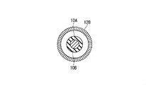
- FIG. 2 is a cross-sectional view illustrating the structure of the electric wire in the AA cross section in FIG.
- the hook-and-loop fastener 12 ⁇ / b> A is wound around the insulating coating 10 ⁇ / b> B in such a manner that the female hook-and-loop fastener is directed to the outside in the radial direction of the electric wire 10.
- FIG. 3 is a perspective view schematically illustrating the structure of the electric wire according to the present embodiment.
- a hook-and-loop fastener 12 ⁇ / b> B that is a connection member is wound around a part of the circumferential direction of the electric wire 10 in the longitudinal direction.
- the hook-and-loop fastener 12B in FIG. 3 is, for example, a male hook-and-loop fastener that faces outward in the radial direction of the electric wire 10 and is wound around a portion that is not an end portion in the longitudinal direction of the electric wire 10.
- the end in the longitudinal direction of the electric wire 10 may be sufficient as the location where the hook_and_loop
- the surface fastener 12B and the insulating coating 10B can be bonded with, for example, a thermoplastic adhesive such as a hot-melt adhesive.
- FIG. 4 is a cross-sectional view illustrating the structure of the electric wire in the BB cross section in FIG.
- the hook-and-loop fastener 12 ⁇ / b> B is wound around the insulating coating 10 ⁇ / b> B in such a manner that the male hook-and-loop fastener is directed outward in the radial direction of the electric wire 10.
- FIG. 5 is a diagram illustrating the connection state between the wires illustrated in FIGS. 1 to 4, that is, the connection wires.
- the outer peripheral surfaces of the hook-and-loop fastener 12 ⁇ / b> A and the hook-and-loop fastener 12 ⁇ / b> B wound around the electric wire 10 are in contact with each other.
- the male surface fastener 12B is caught by the female surface fastener 12A, that is, when the outer peripheral surface of the male surface fastener 12B and the outer peripheral surface of the female surface fastener 12A are engaged, the surface fastener 12A and the surface fastener are engaged.
- the fastener 12B is connected.
- the electric wires are connected to each other through the hook-and-loop fastener 12A and the hook-and-loop fastener 12B.
- FIG. 6 is a diagram illustrating another connection state between the electric wires illustrated in FIGS. 1 to 4.
- the hook-and-loop fastener 12 ⁇ / b> A and the hook-and-loop fastener 12 ⁇ / b> B both wound around the end portion of the electric wire 10 come into contact with each other on the outer peripheral surface.
- the male surface fastener 12B is hooked on the female surface fastener 12A, whereby the surface fastener 12A and the surface fastener 12B are connected.
- FIG. 7 is a diagram illustrating another connection state between the wires illustrated in FIGS. 1 to 4.
- the hook-and-loop fastener 12 ⁇ / b> A and the hook-and-loop fastener 12 ⁇ / b> B both wound around the end portion of the electric wire 10 come into contact with each other on the outer peripheral surface.
- both the hook-and-loop fastener 12A and the hook-and-loop fastener 12B are wound around the left end of the electric wire 10 in FIG. They are connected at the left end in FIG.
- FIG. 8 is a side view schematically illustrating the structure of the wire connecting device according to the present embodiment.
- the wire connection device includes an upper mold 20, a lower mold 22, and an operation mechanism 24 that moves the upper mold 20 toward or away from the lower mold 22.
- the lower mold 22 is disposed on the base 26.
- the opening width of the lower mold 22 is designed to be wider than the diameter of the hook-and-loop fastener 12 ⁇ / b> B wound around the electric wire 10. Further, the opening width of the lower mold 22 is designed wider than the diameter of the hook-and-loop fastener 12A wound around the electric wire 10.
- a hook-and-loop fastener 12 ⁇ / b> A wound around the electric wire 10 and a hook-and-loop fastener 12 ⁇ / b> B wound around the electric wire 10 are arranged.
- the upper mold 20 is arranged at a position facing the lower mold 22.
- the opening width of the upper mold 20 is designed to be wider than the diameter of the hook-and-loop fastener 12 ⁇ / b> B wound around the electric wire 10. Further, the opening width of the upper mold 20 is designed to be wider than the diameter of the hook-and-loop fastener 12 ⁇ / b> A wound around the electric wire 10.
- the upper die 20 is moved to the lower die 22 by the operation of the operation mechanism 24. approach. By doing so, the hook-and-loop fastener 12A wound around the electric wire 10 and the hook-and-loop fastener 12B wound around the electric wire 10 can be connected.
- the operating mechanism 24 is a mechanism in which the support portion 24B that supports the upper mold 20 moves up and down by driving the solenoid 24A.
- Each of the support portion 24B and the solenoid 24A is rotatably connected to a rod-like member 24D that rotates about a common fulcrum 24C. Therefore, the vertical movement of the solenoid 24A is reflected in the vertical movement of the support portion 24B.
- the support portion 24B is urged by a spring (not shown here) or the like, so that the support portion 24B pushes up the rod-shaped member 24D when the solenoid 24A is not driven. Therefore, when the solenoid 24A is not driven, the upper mold 20 and the lower mold 22 are maintained in a separated state.
- the driving of the solenoid 24A in the vertical direction can be controlled by, for example, a foot pedal (not shown here) disposed under the operator's feet.
- the electric wire connecting device is not limited to the one having the above configuration. That is, if a relatively wide mold corresponding to the hook-and-loop fastener 12A wound around the electric wire 10 and the hook-and-loop fastener 12B wound around the electric wire 10 is provided, for example, a terminal is crimped to the end of the electric wire. Even a crimping device to be used can be used.
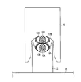
- FIG. 9 is a front view illustrating a state in which the electric wires are arranged between the upper mold and the lower mold.
- the electric wire 10 around which the hook-and-loop fastener 12 ⁇ / b> B is wound and the electric wire 10 around which the hook-and-loop fastener 12 ⁇ / b> A are wound are in the vertical direction in FIG. 9, i.e., the upper mold 20 and the lower mold 22.
- the vertical positions of the hook-and-loop fastener 12A and the hook-and-loop fastener 12B may be reversed.
- the bottom surface of the splice terminal is formed from the top surface of the splice terminal formed by crimping.
- the electric wire 10 with the hook-and-loop fastener 12B wound thereon is arranged so that the hook-and-loop fastener 12A wound around the end of the electric wire 10 faces the bottom surface of the splice terminal, that is, FIG. It is desirable to arrange the electric wire 10 around which the hook-and-loop fastener 12A is wound on the lower side in FIG.
- the core wire 10A exposed at the end of the electric wire 10 may rise from the splice terminal at a portion protruding from the upper surface of the splice terminal. If it does so, when work, such as tape winding, is performed to the splice terminal in which crimping is completed, there arises a problem such that the wound tape is easily broken.
- the core wire 10A exposed at the end of the electric wire 10 is arranged to face the bottom surface of the splice terminal wider than the top surface of the splice terminal, the core wire 10A protruding from the splice terminal can be reduced. Therefore, it is possible to suppress a problem that the tape wound around the splice terminal that has been crimped is broken.
- FIG. 10 is a side view illustrating a connection state between the electric wires arranged between the upper mold and the lower mold.
- the upper mold 20 moves in a direction approaching the lower mold 22
- the upper mold 20 is arranged side by side in the vertical direction, that is, in the direction connecting the upper mold 20 and the lower mold 22.
- the two electric wires 10 are pressed against each other at their outer peripheral surfaces.
- the member that connects both the electric wires 10 is a hook-and-loop fastener, and the hook-and-loop fastener 12B is peeled off from the hook-and-loop fastener 12A, it can be used repeatedly for connecting a plurality of electric wires.
- the electric wire connection training apparatus includes an electric wire to which a male surface fastener 12B is attached in at least a part in the longitudinal direction, and a female surface fastener in at least a part in the longitudinal direction.
- the electric wire to which 12A was attached, the 1st metallic mold, and the 2nd metallic mold are provided.
- the male surface fastener 12B and the female surface fastener 12A are arranged to overlap each other.
- the second mold is disposed at a position facing the first mold.
- the first mold corresponds to the lower mold 22, for example.
- the second mold corresponds to, for example, the upper mold 20.
- a male hook-and-loop fastener or a female hook-and-loop fastener is attached to at least a part of the electric wire 10, so that a plurality of electric wires can be easily connected by simply pressing the hook-and-loop fasteners together. .
- it is an electric wire which has a hook-and-loop fastener, it can be repeatedly used for the said operation
- the male surface fastener 12B is wound around the electric wire 10 in the circumferential direction.
- the female hook-and-loop fastener 12 ⁇ / b> A is wound in the circumferential direction of the electric wire 10.
- the electric wires are connected by engaging the outer peripheral surface of the male hook-and-loop fastener 12B and the outer peripheral surface of the female hook-and-loop fastener 12A.
- the male hook-and-loop fastener or the female hook-and-loop fastener is wound outwardly around at least a part of the electric wire 10, so that a plurality of electric wires can be easily obtained simply by pressing the outer peripheral surfaces of the hook-and-loop fasteners.
- the opening width of the lower mold 22 and the opening width of the upper mold 20 are the diameter of the wound male hook-and-loop fastener 12B and the wound female surface. It is wider than any of the diameters of the fasteners 12A. According to such a configuration, the upper mold 20 and the lower mold 22 are used to connect the hook-and-loop fastener 12B wound around the electric wire 10 and the hook-and-loop fastener 12A wound around the electric wire 10 together. be able to.
- connection electric wire is attached with the male hook-and-loop fastener 12B in at least a part in the longitudinal direction and the female hook-and-loop fastener 12A in at least a part in the longitudinal direction. Electric wire. Then, the electric wires are connected to each other via a male hook-and-loop fastener 12B and a female hook-and-loop fastener 12A.
- a male hook-and-loop fastener or a female hook-and-loop fastener is attached to at least a part of the electric wire 10, so that a plurality of electric wires can be easily connected by simply pressing the hook-and-loop fasteners together. .
- it is an electric wire which has a hook-and-loop fastener, it can be repeatedly used for the said operation
- each component in the embodiment described above is a conceptual unit, and one component is composed of a plurality of structures within the scope of the technique disclosed in this specification.
- one component corresponds to a part of a structure and a case where a plurality of components are provided in one structure are included.
- each component in the embodiment described above includes a structure having another structure or shape as long as the same function is exhibited.
- the material when a material name or the like is described without being particularly specified, the material contains other additives, for example, an alloy or the like unless a contradiction arises. Shall be included.
Landscapes
- Engineering & Computer Science (AREA)
- Business, Economics & Management (AREA)
- Manufacturing & Machinery (AREA)
- Entrepreneurship & Innovation (AREA)
- Physics & Mathematics (AREA)
- Educational Administration (AREA)
- Educational Technology (AREA)
- General Physics & Mathematics (AREA)
- Theoretical Computer Science (AREA)
- Connections Effected By Soldering, Adhesion, Or Permanent Deformation (AREA)
- Manufacturing Of Electrical Connectors (AREA)
Abstract
複数の電線をつなぎ合わせる作業に繰り返し用いることができる電線および接続部材に関する。電線接続訓練装置は、長手方向の少なくとも一部において雄の面ファスナー(12B)が取り付けられた第1の電線(10)と、長手方向の少なくとも一部において雌の面ファスナー(12A)が取り付けられた第2の電線(10)と、第1の電線の雄の面ファスナー、および、第2の電線の雌の面ファスナーが重なって配置される第1の金型(22)と、第1の金型と対向する位置に配置され、かつ、第1の金型に接近することによって、重なって配置された雄の面ファスナーと雌の面ファスナーとを接続させる第2の金型(20)とを備える。
Description
本願明細書に開示される技術は、電線の接続に関するものである。
複数の電線をつなぎ合わせる作業、たとえば、特許文献1に例示されるようなスプライス圧着などには、熟練の技能を必要とする工程が多く含まれる。そのため、当該作業を効率よく行うためには、作業者があらかじめ当該作業の訓練を行っておき、作業者の技能を高めておくことが望ましい。
しかしながら、上記のような複数の電線をつなぎ合わせる作業を行う場合、作業に用いられた電線の接続部分は再度使用することはできなくなるため、使用することができる電線および接続部材には限りがあった。そのため、訓練に用いる場合に限らず、繰り返し上記のような作業に用いることができる電線および接続部材が求められる。
本願明細書に開示される技術は、以上に記載されたような問題を解決するためになされたものであり、複数の電線をつなぎ合わせる作業に繰り返し用いることができる電線および接続部材に関するものである。
本願明細書に開示される技術の第1の態様は、長手方向の少なくとも一部において雄の面ファスナーが取り付けられた第1の電線と、長手方向の少なくとも一部において雌の面ファスナーが取り付けられた第2の電線と、前記第1の電線の前記雄の面ファスナー、および、前記第2の電線の前記雌の面ファスナーが重なって配置される第1の金型と、前記第1の金型と対向する位置に配置され、かつ、前記第1の金型に接近することによって、重なって配置された前記雄の面ファスナーと前記雌の面ファスナーとを接続させる第2の金型とを備える。
本願明細書に開示される技術の第2の態様は、第1の態様に関連し、前記雄の面ファスナーは、前記第1の電線の周方向に巻き付けられ、前記雌の面ファスナーは、前記第2の電線の周方向に巻き付けられ、前記第1の電線と前記第2の電線とは、前記雄の面ファスナーの外周面と前記雌の面ファスナーの外周面とが係合することによって接続される。
本願明細書に開示される技術の第3の態様は、第2の態様に関連し、前記第1の金型の開口幅、および、前記第2の金型の開口幅は、巻き付けられた前記雄の面ファスナーの直径および巻き付けられた前記雌の面ファスナーの直径のいずれよりも広い。
本願明細書に開示される技術の第4の態様は、長手方向の少なくとも一部において雄の面ファスナーが取り付けられた第1の電線と、長手方向の少なくとも一部において雌の面ファスナーが取り付けられた第2の電線とを備え、前記第1の電線と前記第2の電線とは、前記雄の面ファスナーと前記雌の面ファスナーとを介して接続される。
本願明細書に開示される技術の第5の態様は、第4の態様に関連し、前記雄の面ファスナーは、前記第1の電線の周方向に巻き付けられ、前記雌の面ファスナーは、前記第2の電線の周方向に巻き付けられ、前記第1の電線と前記第2の電線とは、前記雄の面ファスナーの外周面と前記雌の面ファスナーの外周面とが係合することによって接続される。
本願明細書に開示される技術の第1の態様によれば、電線の少なくとも一部に、雄の面ファスナーまたは雌の面ファスナーが取り付けられることによって、面ファスナー同士を押し付けるだけで、容易に複数の電線をつなぎ合わせることができる。また、面ファスナーを有する電線同士であれば、面ファスナーを引き剥がすことによって、当該作業に繰り返し用いることができる。さらに、複数本の電線を連続して接続する場合に、一方の手で把持された複数の電線同士が互いに接着されてしまうことがない。そのため、複数の電線をつなぎ合わせる作業が容易となる。
特に、第2の態様および第5の態様によれば、面ファスナーの外周面同士を押し付けるだけで、容易に複数の電線をつなぎ合わせることができる。また、面ファスナーを有する電線同士であれば、面ファスナーを引き剥がすことによって、当該作業に繰り返し用いることができる。
本願明細書に開示される技術の第3の態様によれば、第1の金型と第2の金型とを用いて、電線に巻き付けられた面ファスナーを内包しつつ、これらを接続させることができる。
特に、第4の態様によれば、電線の少なくとも一部に、雄の面ファスナーまたは雌の面ファスナーが取り付けられることによって、面ファスナー同士を押し付けるだけで、容易に複数の電線をつなぎ合わせることができる。また、面ファスナーを有する電線同士であれば、面ファスナーを引き剥がすことによって、当該作業に繰り返し用いることができる。
本願明細書に開示される技術に関する目的と、特徴と、局面と、利点とは、以下に示される詳細な説明と添付図面とによって、さらに明白となる。
以下、添付される図面を参照しながら実施の形態について説明する。
なお、図面は概略的に示されるものであり、説明の便宜のため、適宜、構成の省略、または、構成の簡略化がなされるものである。また、異なる図面にそれぞれ示される構成などの大きさおよび位置の相互関係は、必ずしも正確に記載されるものではなく、適宜変更され得るものである。
また、以下に示される説明では、同様の構成要素には同じ符号を付して図示し、それらの名称と機能とについても同様のものとする。したがって、それらについての詳細な説明を、重複を避けるために省略する場合がある。
また、以下に記載される説明において、「上」、「下」、「左」、「右」、「側」、「底」、「表」または「裏」などの特定の位置と方向とを意味する用語が用いられる場合があっても、これらの用語は、実施の形態の内容を理解することを容易にするために便宜上用いられるものであり、実際に実施される際の方向とは関係しないものである。
また、以下に記載される説明において、「第1の」、または、「第2の」などの序数が用いられる場合があっても、これらの用語は、実施の形態の内容を理解することを容易にするために便宜上用いられるものであり、これらの序数によって生じ得る順序などに限定されるものではない。
<実施の形態>
以下、本実施の形態に関する接続電線、および、電線接続訓練装置について説明する。
以下、本実施の形態に関する接続電線、および、電線接続訓練装置について説明する。
<電線の構造について>
図1は、本実施の形態に関する電線の構造を概略的に例示する斜視図である。図1に例示されるように、電線10は、芯線10Aと、芯線10Aの周囲を覆う絶縁被膜10Bとを備える。また、電線10の長手方向の一部の周方向には、接続部材である面ファスナー12Aが巻き付けられる。
図1は、本実施の形態に関する電線の構造を概略的に例示する斜視図である。図1に例示されるように、電線10は、芯線10Aと、芯線10Aの周囲を覆う絶縁被膜10Bとを備える。また、電線10の長手方向の一部の周方向には、接続部材である面ファスナー12Aが巻き付けられる。
芯線10Aは、銅またはアルミニウムなどの金属を主成分とする線材である。絶縁被膜10Bは、たとえば、ポリエチレン、塩化ビニルまたはポリアミド系ナイロンなどを主成分とする合成樹脂の部材である。
図1における面ファスナー12Aは、たとえば、電線10の径方向の外側に向いた雌の面ファスナーであり、電線10の長手方向における端部に巻き付けられる。なお、面ファスナー12Aが巻き付けられる箇所は、電線10の長手方向における端部でない箇所であってもよい。
面ファスナー12Aと絶縁被膜10Bとの間は、たとえば、ホットメルト系接着剤などの熱可塑性接着剤で接着することができる。
図2は、図1におけるAA断面における電線の構造を例示する断面図である。図2に例示されるように、面ファスナー12Aは、電線10の径方向の外側に雌の面ファスナーが向けられる態様で、絶縁被膜10Bに巻き付けられている。
図3は、本実施の形態に関する電線の構造を概略的に例示する斜視図である。図3に例示されるように、電線10の長手方向の一部の周方向には、接続部材である面ファスナー12Bが巻き付けられる。
図3における面ファスナー12Bは、たとえば、電線10の径方向の外側に向いた雄の面ファスナーであり、電線10の長手方向における端部でない箇所に巻き付けられる。なお、面ファスナー12Bが巻き付けられる箇所は、電線10の長手方向における端部であってもよい。
面ファスナー12Bと絶縁被膜10Bとの間は、たとえば、ホットメルト系接着剤などの熱可塑性接着剤で接着することができる。
図4は、図3におけるBB断面における電線の構造を例示する断面図である。図4に例示されるように、面ファスナー12Bは、電線10の径方向の外側に雄の面ファスナーが向けられる態様で、絶縁被膜10Bに巻き付けられている。
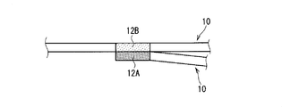
図5は、図1から図4に例示された電線同士の接続状態、すなわち、接続電線を例示する図である。図5に例示されるように、電線10に巻き付けられた面ファスナー12Aと面ファスナー12Bとは、互いの外周面同士が接触する。そして、雄の面ファスナー12Bが雌の面ファスナー12Aに引っかかることによって、すなわち、雄の面ファスナー12Bの外周面と雌の面ファスナー12Aの外周面とが係合することによって、面ファスナー12Aと面ファスナー12Bとが接続される。以上のように、面ファスナー12Aと面ファスナー12Bとを介して、電線同士が接続される。
図6は、図1から図4に例示された電線同士の他の接続状態を例示する図である。図6に例示されるように、双方ともに電線10の端部に巻き付けられた面ファスナー12Aと面ファスナー12Bとが、互いの外周面において接触する。そして、雄の面ファスナー12Bが雌の面ファスナー12Aに引っかかることによって、面ファスナー12Aと面ファスナー12Bとが接続される。
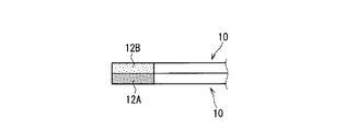
図7は、図1から図4に例示された電線同士の他の接続状態を例示する図である。図7に例示されるように、双方ともに電線10の端部に巻き付けられた面ファスナー12Aと面ファスナー12Bとが、互いの外周面において接触する。なお、図6に例示された電線同士の接続状態とは異なり、面ファスナー12Aと面ファスナー12Bとが、ともに電線10の図7における左側の端部に巻き付けられており、双方の電線10は、図7における左側の端部において接続される。
<電線接続装置について>
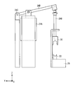
図8は、本実施の形態に関する電線接続装置の構造を概略的に例示する側面図である。図8に例示されるように、電線接続装置は、上金型20と、下金型22と、上金型20を下金型22に対して接近または離間させる動作機構24とを備える。
図8は、本実施の形態に関する電線接続装置の構造を概略的に例示する側面図である。図8に例示されるように、電線接続装置は、上金型20と、下金型22と、上金型20を下金型22に対して接近または離間させる動作機構24とを備える。
下金型22は、基台26上に配置される。下金型22の開口幅は、電線10に巻き付けられた面ファスナー12Bの直径よりも広く設計される。また、下金型22の開口幅は、電線10に巻き付けられた面ファスナー12Aの直径よりも広く設計される。下金型22の上面には、電線10に巻き付けられた面ファスナー12Aおよび電線10に巻き付けられた面ファスナー12Bが配置される。
上金型20は、下金型22に対向する位置に配置される。上金型20の開口幅は、電線10に巻き付けられた面ファスナー12Bの直径よりも広く設計される。また、上金型20の開口幅は、電線10に巻き付けられた面ファスナー12Aの直径よりも広く設計される。上金型20は、電線10に巻き付けられた面ファスナー12Aおよび電線10に巻き付けられた面ファスナー12Bが下金型22の上面に配置された状態で、動作機構24の動作によって下金型22に接近する。そうすることで、電線10に巻き付けられた面ファスナー12Aと電線10に巻き付けられた面ファスナー12Bとを接続させることができる。
動作機構24は、ソレノイド24Aの駆動によって、上金型20を支持する支持部24Bが上下動する機構である。支持部24Bおよびソレノイド24Aはそれぞれ、共通の支点24Cを中心に回転する棒状部材24Dに回転可能に接続される。そのため、ソレノイド24Aの上下動が、支持部24Bの上下動に反映される。
支持部24Bは、バネ(ここでは図示しない)などによって付勢されることで、ソレノイド24Aが駆動しない状態では、支持部24Bが棒状部材24Dを押し上げる。そのため、ソレノイド24Aが駆動しない状態では、上金型20と下金型22とは離間した状態で維持される。
ソレノイド24Aの上下方向の駆動は、たとえば、作業者の足下に配置されるフットペダル(ここでは図示しない)によって制御可能である。
なお、電線接続装置は、上記の構成のものに限られない。すなわち、電線10に巻き付けられた面ファスナー12Aおよび電線10に巻き付けられた面ファスナー12Bに対応する比較的広い幅の金型を備えているものであれば、たとえば、電線の端部に端子を圧着する圧着装置であっても流用することができる。
図9は、上金型と下金型との間に電線が配置された状態を例示する正面図である。図9に例示されるように、面ファスナー12Bが巻き付けられた電線10と、面ファスナー12Aが巻き付けられた電線10とは、図9における上下方向、すなわち、上金型20と下金型22とを結ぶ方向に並んで配置される。なお、当該配列は、たとえば、図6に例示された電線同士の接続状態の場合であっても、または、図7に例示された電線同士の接続状態の場合であっても同様である。また、面ファスナー12Aと面ファスナー12Bとの上下位置は、逆であってもよい。
ただし、本実施の形態に関する電線接続装置を用いて、たとえば、電線同士をスプライス圧着するための訓練を行う場合には、スプライス端子の底面が、圧着によってかしめられて形成されるスプライス端子の上面よりも広い幅を有していることを鑑みて、電線10の端部に巻き付けられた面ファスナー12Aがスプライス端子の底面に対向するように、すなわち、面ファスナー12Bが巻き付けられた電線10を図9における上側に、面ファスナー12Aが巻き付けられた電線10を図9における下側に配置することが望ましい。
これは、電線10の端部において露出する芯線10Aは、スプライス端子の上面からはみ出た部分がスプライス端子から立ち上がる場合がある。そうすると、圧着が完了したスプライス端子にテープ巻きなどの作業を行う場合に、巻き付けられたテープが破れやすくなるなどの不具合が生じる。これに対し、電線10の端部において露出する芯線10Aを、スプライス端子の上面よりも広いスプライス端子の底面に対向させて配置すれば、スプライス端子からはみ出る芯線10Aを少なくすることができる。そのため、圧着が完了したスプライス端子に巻き付けられたテープが破れる不具合を抑制することができる。
図10は、上金型と下金型との間において配置された電線同士の接続状態を例示する側面図である。図10に例示されるように、上金型20が下金型22に接近する方向に移動することによって、上下方向に、すなわち、上金型20と下金型22とを結ぶ方向に並べて配置された双方の電線10は、その外周面が互いに押し付けられる。
そして、雄の面ファスナー12Bが雌の面ファスナー12Aに引っかかることによって、面ファスナー12Aと面ファスナー12Bとが接続される。以上のように、面ファスナー12Aと面ファスナー12Bとを介して、電線10同士が接続される。
さらに、双方の電線10を接続している部材が面ファスナーであることによって、面ファスナー12Aから面ファスナー12Bを引き剥がしてしまえば、複数の電線をつなぎ合わせる作業に繰り返し用いることができる。
<以上に記載された実施の形態によって生じる効果について>
次に、以上に記載された実施の形態によって生じる効果を例示する。なお、以下の説明においては、以上に記載された実施の形態に例示された具体的な構成に基づいて当該効果が記載されるが、同様の効果が生じる範囲で、本願明細書に例示される他の具体的な構成と置き換えられてもよい。
次に、以上に記載された実施の形態によって生じる効果を例示する。なお、以下の説明においては、以上に記載された実施の形態に例示された具体的な構成に基づいて当該効果が記載されるが、同様の効果が生じる範囲で、本願明細書に例示される他の具体的な構成と置き換えられてもよい。
また、以上に記載された実施の形態によれば、電線接続訓練装置は、長手方向の少なくとも一部において雄の面ファスナー12Bが取り付けられた電線と、長手方向の少なくとも一部において雌の面ファスナー12Aが取り付けられた電線と、第1の金型と、第2の金型とを備える。第1の金型は、雄の面ファスナー12B、および、雌の面ファスナー12Aが重なって配置される。第2の金型は、第1の金型と対向する位置に配置される。また、第2の金型は、第1の金型に接近することによって、重なって配置された雄の面ファスナー12Bと雌の面ファスナー12Aとを接続させる。ここで、第1の金型は、たとえば、下金型22に対応するものである。また、第2の金型は、たとえば、上金型20に対応するものである。
このような構成によれば、電線10の少なくとも一部に、雄の面ファスナーまたは雌の面ファスナーが取り付けられることによって、面ファスナー同士を押し付けるだけで、容易に複数の電線をつなぎ合わせることができる。また、面ファスナーを有する電線同士であれば、面ファスナー12Aから面ファスナー12Bを引き剥がすことによって、当該作業に繰り返し用いることができる。さらに、複数本の電線を連続して接続する場合に、一方の手で把持された複数の電線同士が互いに接着されてしまうことがない。そのため、複数の電線をつなぎ合わせる作業が容易となる。
なお、これらの構成以外の本願明細書に例示される他の構成については適宜省略することができる。すなわち、これらの構成のみで、以上に記載された効果を生じさせることができる。
しかしながら、本願明細書に例示される他の構成のうちの少なくとも1つを以上に記載された構成に適宜追加した場合、すなわち、以上に記載された構成としては記載されなかった本願明細書に例示される他の構成を以上に記載された構成に追加した場合でも、同様に以上に記載された効果を生じさせることができる。
また、以上に記載された実施の形態によれば、雄の面ファスナー12Bは、電線10の周方向に巻き付けられる。また、雌の面ファスナー12Aは、電線10の周方向に巻き付けられる。そして、電線同士は、雄の面ファスナー12Bの外周面と雌の面ファスナー12Aの外周面とが係合することによって接続される。このような構成によれば、電線10の少なくとも一部に、雄の面ファスナーまたは雌の面ファスナーが外向きに巻き付けられることによって、面ファスナーの外周面同士を押し付けるだけで、容易に複数の電線をつなぎ合わせることができる。また、面ファスナーを有する電線同士であれば、面ファスナー12Aから面ファスナー12Bを引き剥がすことによって、当該作業に繰り返し用いることができる。
また、以上に記載された実施の形態によれば、下金型22の開口幅、および、上金型20の開口幅は、巻き付けられた雄の面ファスナー12Bの直径および巻き付けられた雌の面ファスナー12Aの直径のいずれよりも広い。このような構成によれば、上金型20と下金型22とを用いて、電線10に巻き付けられた面ファスナー12Bおよび電線10に巻き付けられた面ファスナー12Aを内包しつつ、これらを接続させることができる。
以上に記載された実施の形態によれば、接続電線は、長手方向の少なくとも一部において雄の面ファスナー12Bが取り付けられた電線と、長手方向の少なくとも一部において雌の面ファスナー12Aが取り付けられた電線とを備える。そして、電線同士は、雄の面ファスナー12Bと雌の面ファスナー12Aとを介して接続される。
このような構成によれば、電線10の少なくとも一部に、雄の面ファスナーまたは雌の面ファスナーが取り付けられることによって、面ファスナー同士を押し付けるだけで、容易に複数の電線をつなぎ合わせることができる。また、面ファスナーを有する電線同士であれば、面ファスナー12Aから面ファスナー12Bを引き剥がすことによって、当該作業に繰り返し用いることができる。さらに、複数本の電線を連続して接続する場合に、一方の手で把持された複数の電線同士が互いに接着されてしまうことがない。そのため、複数の電線をつなぎ合わせる作業が容易となる。
なお、これらの構成以外の本願明細書に例示される他の構成については適宜省略することができる。すなわち、少なくともこれらの構成を備えていれば、以上に記載された効果を生じさせることができる。
しかしながら、本願明細書に例示される他の構成のうちの少なくとも1つを以上に記載された構成に適宜追加した場合、すなわち、以上に記載された構成としては記載されなかった本願明細書に例示される他の構成を以上に記載された構成に追加した場合でも、同様に以上に記載された効果を生じさせることができる。
<以上に記載された実施の形態における変形例について>
以上に記載された実施の形態では、それぞれの構成要素の材質、材料、寸法、形状、相対的配置関係または実施の条件などについても記載する場合があるが、これらはすべての局面において例示であって、本願明細書に記載されたものに限られることはないものとする。
以上に記載された実施の形態では、それぞれの構成要素の材質、材料、寸法、形状、相対的配置関係または実施の条件などについても記載する場合があるが、これらはすべての局面において例示であって、本願明細書に記載されたものに限られることはないものとする。
したがって、例示されていない無数の変形例、および、均等物が、本願明細書に開示される技術の範囲内において想定される。たとえば、少なくとも1つの構成要素を変形する場合、追加する場合または省略する場合が含まれるものとする。
また、矛盾が生じない限り、以上に記載された実施の形態において「1つ」備えられるものとして記載された構成要素は、「1つ以上」備えられていてもよいものとする。
さらに、以上に記載された実施の形態におけるそれぞれの構成要素は概念的な単位であって、本願明細書に開示される技術の範囲内には、1つの構成要素が複数の構造物から成る場合と、1つの構成要素がある構造物の一部に対応する場合と、さらには、複数の構成要素が1つの構造物に備えられる場合とを含むものとする。
また、以上に記載された実施の形態におけるそれぞれの構成要素には、同一の機能を発揮する限り、他の構造または形状を有する構造物が含まれるものとする。
また、本願明細書における説明は、本技術に関するすべての目的のために参照され、いずれも、従来技術であると認めるものではない。
また、以上に記載された実施の形態において、特に指定されずに材料名などが記載された場合は、矛盾が生じない限り、当該材料に他の添加物が含まれた、たとえば、合金などが含まれるものとする。
10 電線
10A 芯線
10B 絶縁被膜
12A,12B 面ファスナー
20 上金型
22 下金型
24 動作機構
24A ソレノイド
24B 支持部
24C 支点
24D 棒状部材
26 基台
10A 芯線
10B 絶縁被膜
12A,12B 面ファスナー
20 上金型
22 下金型
24 動作機構
24A ソレノイド
24B 支持部
24C 支点
24D 棒状部材
26 基台
Claims (5)
- 長手方向の少なくとも一部において雄の面ファスナーが取り付けられた第1の電線と、
長手方向の少なくとも一部において雌の面ファスナーが取り付けられた第2の電線と、
前記第1の電線の前記雄の面ファスナー、および、前記第2の電線の前記雌の面ファスナーが重なって配置される第1の金型と、
前記第1の金型と対向する位置に配置され、かつ、前記第1の金型に接近することによって、重なって配置された前記雄の面ファスナーと前記雌の面ファスナーとを接続させる第2の金型とを備える、
電線接続訓練装置。 - 前記雄の面ファスナーは、前記第1の電線の周方向に巻き付けられ、
前記雌の面ファスナーは、前記第2の電線の周方向に巻き付けられ、
前記第1の電線と前記第2の電線とは、前記雄の面ファスナーの外周面と前記雌の面ファスナーの外周面とが係合することによって接続される、
請求項1に記載の電線接続訓練装置。 - 前記第1の金型の開口幅、および、前記第2の金型の開口幅は、巻き付けられた前記雄の面ファスナーの直径および巻き付けられた前記雌の面ファスナーの直径のいずれよりも広い、
請求項2に記載の電線接続訓練装置。 - 長手方向の少なくとも一部において雄の面ファスナーが取り付けられた第1の電線と、
長手方向の少なくとも一部において雌の面ファスナーが取り付けられた第2の電線とを備え、
前記第1の電線と前記第2の電線とは、前記雄の面ファスナーと前記雌の面ファスナーとを介して接続される、
接続電線。 - 前記雄の面ファスナーは、前記第1の電線の周方向に巻き付けられ、
前記雌の面ファスナーは、前記第2の電線の周方向に巻き付けられ、
前記第1の電線と前記第2の電線とは、前記雄の面ファスナーの外周面と前記雌の面ファスナーの外周面とが係合することによって接続される、
請求項4に記載の接続電線。
Applications Claiming Priority (2)
| Application Number | Priority Date | Filing Date | Title |
|---|---|---|---|
| JP2016-204966 | 2016-10-19 | ||
| JP2016204966A JP2018067440A (ja) | 2016-10-19 | 2016-10-19 | 電線接続訓練装置、および、接続電線 |
Publications (1)
| Publication Number | Publication Date |
|---|---|
| WO2018074202A1 true WO2018074202A1 (ja) | 2018-04-26 |
Family
ID=62018434
Family Applications (1)
| Application Number | Title | Priority Date | Filing Date |
|---|---|---|---|
| PCT/JP2017/035778 Ceased WO2018074202A1 (ja) | 2016-10-19 | 2017-10-02 | 電線接続訓練装置、および、接続電線 |
Country Status (2)
| Country | Link |
|---|---|
| JP (1) | JP2018067440A (ja) |
| WO (1) | WO2018074202A1 (ja) |
Families Citing this family (1)
| Publication number | Priority date | Publication date | Assignee | Title |
|---|---|---|---|---|
| JP2024064548A (ja) * | 2022-10-28 | 2024-05-14 | 有限会社オオコウ電設 | 電気工事練習用ケーブル |
Citations (7)
| Publication number | Priority date | Publication date | Assignee | Title |
|---|---|---|---|---|
| JPS4943795U (ja) * | 1972-07-22 | 1974-04-17 | ||
| JPH01110591U (ja) * | 1988-01-19 | 1989-07-26 | ||
| JPH0664324U (ja) * | 1993-02-19 | 1994-09-09 | 住友電装株式会社 | フラット・ハーネスおよび該フラット・ハーネスの固定構造 |
| JPH1167416A (ja) * | 1997-08-27 | 1999-03-09 | Sumitomo Wiring Syst Ltd | 端子圧着ユニットを調整するためのニードルユニットおよび台座ならびにニードルユニットの調整方法 |
| JPH11155226A (ja) * | 1997-11-21 | 1999-06-08 | Sumitomo Wiring Syst Ltd | ワイヤハーネスおよび該ワイヤハーネスの取付構造 |
| US5949026A (en) * | 1997-12-01 | 1999-09-07 | Deflorio; Ralph E | Tangle-resistant electrical test leads |
| JP2005285642A (ja) * | 2004-03-30 | 2005-10-13 | Sumitomo Wiring Syst Ltd | 端子挿入訓練装置 |
-
2016
- 2016-10-19 JP JP2016204966A patent/JP2018067440A/ja active Pending
-
2017
- 2017-10-02 WO PCT/JP2017/035778 patent/WO2018074202A1/ja not_active Ceased
Patent Citations (7)
| Publication number | Priority date | Publication date | Assignee | Title |
|---|---|---|---|---|
| JPS4943795U (ja) * | 1972-07-22 | 1974-04-17 | ||
| JPH01110591U (ja) * | 1988-01-19 | 1989-07-26 | ||
| JPH0664324U (ja) * | 1993-02-19 | 1994-09-09 | 住友電装株式会社 | フラット・ハーネスおよび該フラット・ハーネスの固定構造 |
| JPH1167416A (ja) * | 1997-08-27 | 1999-03-09 | Sumitomo Wiring Syst Ltd | 端子圧着ユニットを調整するためのニードルユニットおよび台座ならびにニードルユニットの調整方法 |
| JPH11155226A (ja) * | 1997-11-21 | 1999-06-08 | Sumitomo Wiring Syst Ltd | ワイヤハーネスおよび該ワイヤハーネスの取付構造 |
| US5949026A (en) * | 1997-12-01 | 1999-09-07 | Deflorio; Ralph E | Tangle-resistant electrical test leads |
| JP2005285642A (ja) * | 2004-03-30 | 2005-10-13 | Sumitomo Wiring Syst Ltd | 端子挿入訓練装置 |
Also Published As
| Publication number | Publication date |
|---|---|
| JP2018067440A (ja) | 2018-04-26 |
Similar Documents
| Publication | Publication Date | Title |
|---|---|---|
| JP2013025997A (ja) | 電線の接続方法 | |
| US20200361404A1 (en) | Wire harness fixing structure and wire harness | |
| JP2015089311A (ja) | ワイヤハーネスの止水構造 | |
| CN103904803B (zh) | 发卡与具备发卡的发卡形绕组电动机 | |
| US20150236494A1 (en) | Terminal-formed wire and manufacturing method thereof | |
| WO2020085038A1 (ja) | 電線の接続構造、および、電線の接続方法 | |
| WO2018074202A1 (ja) | 電線接続訓練装置、および、接続電線 | |
| JP6747212B2 (ja) | フラット電線の固定構造 | |
| JP5609685B2 (ja) | ワイヤハーネスに設けられるシールド体の製造方法 | |
| JP2013535632A5 (ja) | ||
| JP2019121467A (ja) | 端子付き電線、及び端子付き電線の製造方法 | |
| US9530538B2 (en) | Wire harness manufacturing method and wire harness | |
| WO2018207641A1 (ja) | 配線モジュール、複合配線モジュール及び配線モジュール付固定対象部材 | |
| CN102785329B (zh) | 一种调节器刷架成型方法 | |
| US20170237183A1 (en) | Electrical wire with terminal fitting and method of manufacturing electrical wire with terminal fitting | |
| JP2018078060A (ja) | 電線の接合構造及びワイヤハーネス | |
| US10455701B2 (en) | Resin board structure and method for fabricating the same | |
| JP6645329B2 (ja) | モールド部付電線 | |
| CN108886205A (zh) | 导体的连接结构以及线束 | |
| JP5510739B2 (ja) | 端子金具付き電線および端子金具 | |
| WO2017169795A1 (ja) | ワイヤーハーネス及びその製造方法 | |
| JP2009163974A (ja) | 細線同軸ケーブル周りの防水シールおよびその製造方法 | |
| JP2013257967A (ja) | ワイヤハーネス | |
| JP2014235777A (ja) | 電線と端子の接合構造及び接合方法 | |
| JP6647132B2 (ja) | 電線のジョイント構造および製造方法 |
Legal Events
| Date | Code | Title | Description |
|---|---|---|---|
| 121 | Ep: the epo has been informed by wipo that ep was designated in this application |
Ref document number: 17861980 Country of ref document: EP Kind code of ref document: A1 |
|
| NENP | Non-entry into the national phase |
Ref country code: DE |
|
| 122 | Ep: pct application non-entry in european phase |
Ref document number: 17861980 Country of ref document: EP Kind code of ref document: A1 |