WO2018062514A1 - ポリオレフィン系発泡シート、その製造方法及び粘着テープ - Google Patents
ポリオレフィン系発泡シート、その製造方法及び粘着テープ Download PDFInfo
- Publication number
- WO2018062514A1 WO2018062514A1 PCT/JP2017/035566 JP2017035566W WO2018062514A1 WO 2018062514 A1 WO2018062514 A1 WO 2018062514A1 JP 2017035566 W JP2017035566 W JP 2017035566W WO 2018062514 A1 WO2018062514 A1 WO 2018062514A1
- Authority
- WO
- WIPO (PCT)
- Prior art keywords
- polyolefin
- sheet
- foamed sheet
- foam sheet
- resin
- Prior art date
- Legal status (The legal status is an assumption and is not a legal conclusion. Google has not performed a legal analysis and makes no representation as to the accuracy of the status listed.)
- Ceased
Links
Images

Classifications
-
- C—CHEMISTRY; METALLURGY
- C08—ORGANIC MACROMOLECULAR COMPOUNDS; THEIR PREPARATION OR CHEMICAL WORKING-UP; COMPOSITIONS BASED THEREON
- C08J—WORKING-UP; GENERAL PROCESSES OF COMPOUNDING; AFTER-TREATMENT NOT COVERED BY SUBCLASSES C08B, C08C, C08F, C08G or C08H
- C08J9/00—Working-up of macromolecular substances to porous or cellular articles or materials; After-treatment thereof
- C08J9/22—After-treatment of expandable particles; Forming foamed products
- C08J9/228—Forming foamed products
-
- B—PERFORMING OPERATIONS; TRANSPORTING
- B32—LAYERED PRODUCTS
- B32B—LAYERED PRODUCTS, i.e. PRODUCTS BUILT-UP OF STRATA OF FLAT OR NON-FLAT, e.g. CELLULAR OR HONEYCOMB, FORM
- B32B27/00—Layered products comprising a layer of synthetic resin
- B32B27/16—Layered products comprising a layer of synthetic resin specially treated, e.g. irradiated
-
- B—PERFORMING OPERATIONS; TRANSPORTING
- B32—LAYERED PRODUCTS
- B32B—LAYERED PRODUCTS, i.e. PRODUCTS BUILT-UP OF STRATA OF FLAT OR NON-FLAT, e.g. CELLULAR OR HONEYCOMB, FORM
- B32B27/00—Layered products comprising a layer of synthetic resin
- B32B27/32—Layered products comprising a layer of synthetic resin comprising polyolefins
-
- C—CHEMISTRY; METALLURGY
- C08—ORGANIC MACROMOLECULAR COMPOUNDS; THEIR PREPARATION OR CHEMICAL WORKING-UP; COMPOSITIONS BASED THEREON
- C08J—WORKING-UP; GENERAL PROCESSES OF COMPOUNDING; AFTER-TREATMENT NOT COVERED BY SUBCLASSES C08B, C08C, C08F, C08G or C08H
- C08J9/00—Working-up of macromolecular substances to porous or cellular articles or materials; After-treatment thereof
- C08J9/04—Working-up of macromolecular substances to porous or cellular articles or materials; After-treatment thereof using blowing gases generated by a previously added blowing agent
- C08J9/06—Working-up of macromolecular substances to porous or cellular articles or materials; After-treatment thereof using blowing gases generated by a previously added blowing agent by a chemical blowing agent
- C08J9/10—Working-up of macromolecular substances to porous or cellular articles or materials; After-treatment thereof using blowing gases generated by a previously added blowing agent by a chemical blowing agent developing nitrogen, the blowing agent being a compound containing a nitrogen-to-nitrogen bond
-
- C—CHEMISTRY; METALLURGY
- C08—ORGANIC MACROMOLECULAR COMPOUNDS; THEIR PREPARATION OR CHEMICAL WORKING-UP; COMPOSITIONS BASED THEREON
- C08L—COMPOSITIONS OF MACROMOLECULAR COMPOUNDS
- C08L23/00—Compositions of homopolymers or copolymers of unsaturated aliphatic hydrocarbons having only one carbon-to-carbon double bond; Compositions of derivatives of such polymers
- C08L23/02—Compositions of homopolymers or copolymers of unsaturated aliphatic hydrocarbons having only one carbon-to-carbon double bond; Compositions of derivatives of such polymers not modified by chemical after-treatment
- C08L23/04—Homopolymers or copolymers of ethene
- C08L23/06—Polyethylene
-
- C—CHEMISTRY; METALLURGY
- C09—DYES; PAINTS; POLISHES; NATURAL RESINS; ADHESIVES; COMPOSITIONS NOT OTHERWISE PROVIDED FOR; APPLICATIONS OF MATERIALS NOT OTHERWISE PROVIDED FOR
- C09J—ADHESIVES; NON-MECHANICAL ASPECTS OF ADHESIVE PROCESSES IN GENERAL; ADHESIVE PROCESSES NOT PROVIDED FOR ELSEWHERE; USE OF MATERIALS AS ADHESIVES
- C09J7/00—Adhesives in the form of films or foils
- C09J7/20—Adhesives in the form of films or foils characterised by their carriers
- C09J7/22—Plastics; Metallised plastics
- C09J7/26—Porous or cellular plastics
-
- C—CHEMISTRY; METALLURGY
- C08—ORGANIC MACROMOLECULAR COMPOUNDS; THEIR PREPARATION OR CHEMICAL WORKING-UP; COMPOSITIONS BASED THEREON
- C08J—WORKING-UP; GENERAL PROCESSES OF COMPOUNDING; AFTER-TREATMENT NOT COVERED BY SUBCLASSES C08B, C08C, C08F, C08G or C08H
- C08J2323/00—Characterised by the use of homopolymers or copolymers of unsaturated aliphatic hydrocarbons having only one carbon-to-carbon double bond; Derivatives of such polymers
- C08J2323/02—Characterised by the use of homopolymers or copolymers of unsaturated aliphatic hydrocarbons having only one carbon-to-carbon double bond; Derivatives of such polymers not modified by chemical after treatment
- C08J2323/04—Homopolymers or copolymers of ethene
- C08J2323/06—Polyethene
-
- C—CHEMISTRY; METALLURGY
- C08—ORGANIC MACROMOLECULAR COMPOUNDS; THEIR PREPARATION OR CHEMICAL WORKING-UP; COMPOSITIONS BASED THEREON
- C08L—COMPOSITIONS OF MACROMOLECULAR COMPOUNDS
- C08L2207/00—Properties characterising the ingredient of the composition
- C08L2207/06—Properties of polyethylene
- C08L2207/066—LDPE (radical process)
-
- C—CHEMISTRY; METALLURGY
- C08—ORGANIC MACROMOLECULAR COMPOUNDS; THEIR PREPARATION OR CHEMICAL WORKING-UP; COMPOSITIONS BASED THEREON
- C08L—COMPOSITIONS OF MACROMOLECULAR COMPOUNDS
- C08L2314/00—Polymer mixtures characterised by way of preparation
- C08L2314/06—Metallocene or single site catalysts
Definitions
- the present invention relates to a polyolefin foam sheet, a method for producing the same, and an adhesive tape having the polyolefin foam sheet.
- a sealing material or a shock absorbing material made of a foamed sheet, and an adhesive tape based on the foamed sheet are used.
- a display device used in the above-described electronic apparatus generally has a structure in which a protective panel is installed on a display panel such as an LCD. The protective panel is bonded to a frame portion outside the display panel. For this purpose, an adhesive tape based on a foam sheet is used.
- a foam sheet used in an electronic device a crosslinked polyolefin resin foam sheet obtained by foaming and crosslinking a foamable polyolefin resin sheet containing a pyrolytic foaming agent is known (for example, patents). Reference 1).
- the frame portion outside the display panel is becoming narrower due to downsizing of electronic devices and upsizing of display devices. Therefore, the foam sheet is required not only to be relatively thick but also to have high flexibility and durability even when it is thinned.
- the present invention has been made in view of the above circumstances, and an object thereof is to provide a foam sheet having high flexibility and durability even when the sheet is thinned.
- the present invention provides the following [1] to [10].
- [1] A polyolefin-based foamed sheet containing a polyolefin resin and obtained by foaming a crosslinked foamable composition, wherein the polyolefin-based foamed sheet has an average molecular weight between crosslinking points of 15000 to 30000 in the foamable composition .
- [2] The polyolefin-based foamed sheet according to the above [1], wherein the polyolefin resin is a polyethylene resin.
- [3] The polyolefin-based foamed sheet according to the above [2], wherein the polyolefin resin is linear low-density polyethylene polymerized with a metallocene compound polymerization catalyst.
- An adhesive tape comprising the polyolefin foam sheet according to any one of the above [1] to [8] and an adhesive layer provided on at least one surface of the polyolefin foam sheet.
- a polyolefin-based foamed sheet according to the present invention (hereinafter, also simply referred to as “foamed sheet”) is a foamed sheet obtained by foaming a crosslinked foamable composition containing a polyolefin resin, and having a crosslinked foaming property.
- the average molecular weight between cross-linking points in the composition is 15000 to 30000. In the present invention, when the average molecular weight between cross-linking points is less than 15000 or exceeds 30000, impact resistance, interlayer strength and the like are lowered and durability is insufficient.
- the average molecular weight between crosslinking points is preferably 20000 to 29000, more preferably 23000 to 29000.
- polyolefin resin examples of the polyolefin resin used for the foamed sheet include a polyethylene resin, a polypropylene resin, and an ethylene-vinyl acetate copolymer. Among these, a polyethylene resin is preferable.
- the polyethylene resin include a polyethylene resin polymerized with a polymerization catalyst such as a Ziegler-Natta compound, a metallocene compound, and a chromium oxide compound.
- a polyethylene resin polymerized with a polymerization catalyst of a metallocene compound is used.
- the polyethylene resin is preferably linear low density polyethylene.
- linear low density polyethylene By using linear low density polyethylene, the foamed sheet obtained can have high flexibility and can be made thinner.
- the linear low-density polyethylene is more preferably obtained using a polymerization catalyst such as a metallocene compound.
- the linear low density polyethylene is obtained by copolymerizing ethylene (for example, 75% by mass or more, preferably 90% by mass or more with respect to the total amount of monomers) and, if necessary, a small amount of ⁇ -olefin. More preferred is linear low density polyethylene.
- ⁇ -olefin examples include propylene, 1-butene, 1-pentene, 4-methyl-1-pentene, 1-hexene, 1-heptene, and 1-octene. Of these, ⁇ -olefins having 4 to 10 carbon atoms are preferred.
- Polyethylene resin for example the density of the above-mentioned linear low density polyethylene is preferably 0.870 ⁇ 0.910g / cm 3, more preferably 0.875 ⁇ 0.907g / cm 3, 0.880 ⁇ 0.905g / Cm 3 is more preferable.
- the polyethylene resin a plurality of polyethylene resins can be used, and a polyethylene resin outside the above-described density range may be added.
- metallocene compound examples include compounds such as a bis (cyclopentadienyl) metal complex having a structure in which a transition metal is sandwiched between ⁇ -electron unsaturated compounds. More specifically, tetravalent transition metals such as titanium, zirconium, nickel, palladium, hafnium, and platinum have one or more cyclopentadienyl rings or their analogs as ligands (ligands). Can be mentioned. Metallocene compounds have uniform active site properties and each active site has the same activity.
- a polymer synthesized using a metallocene compound has high uniformity in molecular weight, molecular weight distribution, composition, composition distribution, etc., so when a sheet containing a polymer synthesized using a metallocene compound is crosslinked, the crosslinking is uniform. Proceed to. Since the uniformly cross-linked sheet is uniformly foamed, it is easy to make the size of the bubble diameter uniform. Moreover, since it can extend
- Examples of the ligand include a cyclopentadienyl ring and an indenyl ring. These cyclic compounds may be substituted with a hydrocarbon group, a substituted hydrocarbon group or a hydrocarbon-substituted metalloid group.
- Examples of the hydrocarbon group include a methyl group, an ethyl group, various propyl groups, various butyl groups, various amyl groups, various hexyl groups, 2-ethylhexyl groups, various heptyl groups, various octyl groups, various nonyl groups, and various decyl groups. , Various cetyl groups, phenyl groups and the like.
- the “various” means various isomers including n-, sec-, tert-, and iso-. Moreover, what polymerized the cyclic compound as an oligomer may be used as a ligand. In addition to ⁇ -electron unsaturated compounds, monovalent anion ligands such as chlorine and bromine or divalent anion chelate ligands, hydrocarbons, alkoxides, arylamides, aryloxides, amides, arylamides, phosphides, aryls Phosphide or the like may be used.
- monovalent anion ligands such as chlorine and bromine or divalent anion chelate ligands, hydrocarbons, alkoxides, arylamides, aryloxides, amides, arylamides, phosphides, aryls Phosphide or the like may be used.
- metallocene compounds containing tetravalent transition metals and ligands include, for example, cyclopentadienyl titanium tris (dimethylamide), methylcyclopentadienyl titanium tris (dimethylamide), bis (cyclopentadienyl) titanium dichloride, dimethyl And silyltetramethylcyclopentadienyl-t-butylamidozirconium dichloride.
- the metallocene compound exhibits an action as a catalyst in the polymerization of various olefins by combining with a specific cocatalyst (co-catalyst).
- specific cocatalyst include methylaluminoxane (MAO) and boron compounds.
- the proportion of the cocatalyst used with respect to the metallocene compound is preferably 100,000 to 1,000,000 mole times, more preferably 50 to 5,000 mole times.
- Examples of the ethylene-vinyl acetate copolymer used as the polyolefin resin include an ethylene-vinyl acetate copolymer containing 50% by mass or more of ethylene.
- Examples of the polypropylene resin include polypropylene and a propylene- ⁇ -olefin copolymer containing 50% by mass or more of propylene. These may be used alone or in combination of two or more.
- ⁇ -olefin constituting the propylene- ⁇ -olefin copolymer examples include ethylene, 1-butene, 1-pentene, 4-methyl-1-pentene, 1-hexene, 1-heptene, 1- Among these, ⁇ -olefins having 6 to 12 carbon atoms are preferable.
- the above linear low density polyethylene may be used alone, or may be used in combination with other polyolefin resins.
- the ratio of the other polyolefin resin to the total amount of the linear low density polyethylene and the other polyolefin resin is preferably 75% by mass or less, and 50% by mass or less. Is more preferable, and it is further more preferable that it is 30 mass% or less.
- the other polyolefin resin is preferably an ethylene-vinyl acetate copolymer.
- the ratio of the polyolefin resin to the total amount of the resin is preferably 60% by mass or more, more preferably 70% by mass or more, and still more preferably 80% by mass or more.
- the resin other than the polyolefin resin include styrene-based thermoplastic elastomers and ethylene-propylene-based thermoplastic elastomers such as EPDM.
- the foam sheet is cross-linked, and the degree of cross-linking is preferably 20 to 70% by mass.
- the degree of cross-linking is more preferably 30 to 65% by mass, and further preferably 35 to 60% by mass.
- the foaming ratio of the foamed sheet is preferably 1.2 to 8 cm 3 / g.
- the foaming ratio of the foamed sheet is more preferably 1.3 to 3 cm 3 / g, and still more preferably 1.5 to 2.3 cm 3 / g.
- the density of the foamed sheet is obtained according to JIS K7222, and the reciprocal thereof is taken as the foaming ratio.
- the foam sheet is a closed cell. That the bubbles are closed cells means that the ratio of closed cells to all bubbles (referred to as closed cell rate) is 70% or more.
- the closed cell ratio is preferably 80% or more, more preferably 90% or more.
- the closed cell ratio can be determined according to ASTM D2856 (1998). Commercially available measuring instruments include a dry automatic densitometer Accupic 1330 and the like.
- the closed cell ratio is measured in the following manner.
- a test piece having a flat square shape with a side of 5 cm and a constant thickness is cut out from the foam sheet.
- the thickness of the test piece is measured, the apparent volume V 1 of the test piece is calculated, and the weight W 1 of the test piece is measured.
- the apparent volume V 2 occupied by the bubbles is calculated based on the following formula.
- the density of the resin constituting the test piece is 1 g / cm 3 .
- Apparent volume occupied by bubbles V 2 V 1 ⁇ W 1
- the test piece is submerged in distilled water at 23 ° C. to a depth of 100 mm from the water surface, and a pressure of 15 kPa is applied to the test piece over 3 minutes.
- the thickness of the foamed sheet is preferably 0.02 to 0.8 mm. In the present invention, even within such a relatively wide thickness range, by setting the average molecular weight between cross-linking points within a predetermined range as described above, durability such as impact resistance is ensured while ensuring the flexibility of the foam sheet. It becomes possible to improve the property.
- the thickness of the foam sheet is more preferably 0.08 to 0.50 mm, and further preferably 0.10 to 0.40 mm.
- the foamed sheet is not particularly limited, but may be processed into a thin line shape. For example, the foamed sheet may be used with a width of 10 mm or less. For example, it may be 5 mm or less, and further 1 mm or less.
- the width of the foamed sheet When the width of the foamed sheet is narrowed, it can be suitably used inside a miniaturized electronic device. Moreover, even if the width
- variety of a foamed sheet is not specifically limited, For example, a 0.1 mm or more thing may be sufficient and a 0.2 mm or more thing may be sufficient.
- the planar shape of the foam sheet is not particularly limited, but may be an elongated rectangular shape, a frame shape, an L shape, a U shape, or the like, and other than these shapes, other shapes such as a normal square shape, a circular shape, etc. Any shape is possible.
- the 25% compressive strength of the foamed sheet is preferably 10 to 2000 kPa, more preferably 4000 to 2000 kPa, and still more preferably 800 to 1500 kPa.
- the foamed sheet has impact absorbability and sealability, and can be suitably used as a buffer absorbent and a sealant.
- 25% compressive strength means what measured the foamed sheet based on JISK6767.
- the foam sheet preferably has an impact resistance evaluation result in the range of 25 to 50 cm.
- the foamed sheet preferably has an interlayer strength of 4.3 MPa or more, and more preferably 4.8 MPa or more.
- the impact resistance evaluation and the value of the interlayer strength are measured according to the methods of Examples described later.
- the foamed sheet has an average cell diameter of MD and TD of preferably 120 ⁇ m or less, more preferably 100 ⁇ m or less, still more preferably 80 ⁇ m or less, and an average cell diameter of ZD of 80 ⁇ m or less, preferably 50 m or less, more preferably 40 ⁇ m.
- microcell the average cell diameter of MD and TD of preferably 120 ⁇ m or less, more preferably 100 ⁇ m or less, still more preferably 80 ⁇ m or less, and an average cell diameter of ZD of 80 ⁇ m or less, preferably 50 m or less, more preferably 40 ⁇ m.
- microcells can be easily formed by setting the average molecular weight between cross-linking points in the above-described range and setting the cross-linking degree and the expansion ratio in the above-described preferable ranges.
- each of the average bubble diameters of MD and TD is preferably 10 ⁇ m or more, more preferably 20 ⁇ m or more, and further preferably 25 ⁇ m or more, from the viewpoint of ease of production.
- the average cell diameter of ZD is preferably 5 ⁇ m or more, more preferably 10 m or more, and further preferably 15 ⁇ m or more.
- the ratio of the average bubble diameter of MD to the average bubble diameter of bubbles (hereinafter also referred to as “MD / ZD”) is 1 to 8, and the ratio of the average bubble diameter of TD to the average bubble diameter of ZD ( Hereinafter, “TD / ZD” is also preferably 1 to 8. More preferably, MD / ZD is 2 to 7, and TD / ZD is 2 to 7.
- the average bubble diameter is measured in the following manner.
- a foam sheet cut into a 50 mm square was prepared as a foam sample for measurement. This was immersed in liquid nitrogen for 1 minute and then cut in the thickness direction along the MD, TD, and ZD directions with a razor blade. This cross-section is taken with a digital microscope (Keyence Co., Ltd. “VHX-900”), and a 200 times magnified photograph is taken. All of the cross sections present in a length of 2 mm in each of the MD, TD, and ZD directions. The bubble diameter of each bubble was measured, and the operation was repeated 5 times. And the average value of all the bubbles was made into the average bubble diameter of MD direction, TD direction, and ZD direction.
- the MD direction means Machine direction and coincides with the extrusion direction and the like
- the TD direction means Transverse direction, which is a direction orthogonal to the MD direction, and is a sheet-like foam (foamed sheet). ) In the direction parallel to the sheet surface.
- the ZD direction is the thickness direction of the foam and is a direction perpendicular to both the MD direction and the TD direction.
- the foam sheet of the present invention is preferably formed by foaming a foamable composition containing a pyrolytic foaming agent in addition to the resin.
- a pyrolytic foaming agent an organic foaming agent or an inorganic foaming agent can be used.
- Organic foaming agents include azodicarbonamide, azodicarboxylic acid metal salts (such as barium azodicarboxylate), azo compounds such as azobisisobutyronitrile, nitroso compounds such as N, N′-dinitrosopentamethylenetetramine, And hydrazine derivatives such as hydrazodicarbonamide, 4,4′-oxybis (benzenesulfonylhydrazide) and toluenesulfonylhydrazide, and semicarbazide compounds such as toluenesulfonyl semicarbazide.
- azodicarbonamide azodicarboxylic acid metal salts (such as barium azodicarboxylate)
- azo compounds such as azobisisobutyronitrile
- nitroso compounds such as N, N′-dinitrosopentamethylenetetramine
- hydrazine derivatives such as hydrazodicarbonamide, 4,4′
- the inorganic foaming agent examples include ammonium acid, sodium carbonate, ammonium hydrogen carbonate, sodium hydrogen carbonate, ammonium nitrite, sodium borohydride, anhydrous monosodium citrate, and the like.
- an azo compound is preferable and azodicarbonamide is particularly preferable from the viewpoint of obtaining fine bubbles and from the viewpoints of economy and safety.
- These pyrolytic foaming agents can be used alone or in combination of two or more.
- the blending amount of the thermally decomposable foaming agent in the foamable composition is preferably 1 to 10 parts by weight, more preferably 1 to 7 parts by weight, and even more preferably 1.5 to 3.5 parts by weight with respect to 100 parts by weight of the resin. Part by mass.
- a foamable composition contains a cell nucleus regulator in addition to the said resin and a thermal decomposition type foaming agent.
- the cell nucleus adjusting agent include zinc compounds such as zinc oxide and zinc stearate, and organic compounds such as citric acid and urea. Among these, zinc oxide is more preferable.
- the blending amount of the cell nucleus adjusting agent is preferably 0.4 to 8 parts by mass, more preferably 0.5 to 5 parts by mass, and further preferably 0.8 to 2.5 parts by mass with respect to 100 parts by mass of the resin. It is.
- the foamable composition contains additives generally used for foams such as antioxidants, heat stabilizers, colorants, flame retardants, antistatic agents, fillers, etc. You may do it.
- the method for producing the foamed sheet is not particularly limited.
- the foamed sheet is produced by heating a crosslinked foamable composition containing a polyolefin resin and a pyrolyzable foaming agent to foam the pyrolyzable foaming agent.
- the manufacturing method includes the following steps (1) to (4).
- the method of forming the resin sheet is not particularly limited.
- the polyolefin resin and the additive are supplied to an extruder and melt-kneaded, and the foamable composition is extruded into a sheet form from the extruder. What is necessary is just to shape
- a method for crosslinking the foamable composition in the step (2) a method of irradiating the resin sheet with ionizing radiation such as electron beam, ⁇ ray, ⁇ ray, ⁇ ray and the like is used.
- the irradiation amount of the ionizing radiation may be adjusted so that the degree of cross-linking of the foamed sheet to be obtained falls within the desired range described above, but is preferably 5 to 15 Mrad, and more preferably 6 to 13 Mrad.
- the heating temperature when the foamable composition is heated to foam the pyrolyzable foaming agent may be not less than the foaming temperature of the pyrolyzable foaming agent, preferably 200 to 300 ° C. The temperature is preferably 220 to 280 ° C.
- the stretching of the foam sheet in the step (4) may be performed after foaming the resin sheet to obtain the foam sheet, or may be performed while foaming the resin sheet.
- the foamed sheet when the foamed sheet is stretched after foaming the resin sheet, the foamed sheet may be stretched continuously while maintaining the molten state at the time of foaming without cooling the foamed sheet. After the foam sheet is cooled, the foam sheet may be stretched again by heating it to a molten or softened state.
- the draw ratio of the foamed sheet in one or both of the MD direction and the TD direction is preferably 1.1 to 5.0 times, more preferably 1.5 to 4.0 times.
- the foamed sheet When the draw ratio is set to the above lower limit or more, the flexibility and tensile strength of the foam sheet are likely to be good. On the other hand, when the upper limit value is not reached, the foamed sheet is prevented from breaking during stretching, or the foaming gas escapes from the foamed sheet being foamed and the foaming ratio is significantly reduced. And the quality is easy to be uniform. Further, the foamed sheet may be heated to, for example, 100 to 280 ° C., preferably 150 to 260 ° C. during stretching. Moreover, it is preferable to provide the process of quenching a foam sheet, after extending a foam sheet to one or both of MD direction and TD direction.
- the method of quenching is not particularly limited, for example, it may be performed by a method in which a foam sheet is brought into contact with a metal roll through which cooling water is passed.
- a foamed sheet may be obtained by a method other than the above.
- an organic peroxide may be blended in advance in the foamable composition, and crosslinking may be performed by a method in which the foamable composition is heated to decompose the organic peroxide. Good.
- the step (4) that is, stretching of the foam sheet may be omitted.
- the foam sheet is not particularly limited, for example, it is preferably used inside an electronic device. Since the foamed sheet of the present invention has high durability even if it is thinned, the foamed sheet can be suitably used particularly in various portable electronic devices where a space for arranging the foamed sheet is small. Examples of the portable electronic device include a mobile phone, a camera, a game device, an electronic notebook, and a personal computer.
- the foam sheet can be used as an impact absorbing material and a sealing material inside the electronic device.
- the pressure-sensitive adhesive tape includes, for example, a foam sheet and a pressure-sensitive adhesive layer provided on at least one surface of the foam sheet, but a double-sided pressure-sensitive adhesive tape provided with a pressure-sensitive adhesive layer on both sides is preferable.
- the thickness of the pressure-sensitive adhesive layer constituting the pressure-sensitive adhesive tape is preferably 5 to 200 ⁇ m.
- the thickness of the pressure-sensitive adhesive layer is more preferably 7 to 150 ⁇ m, still more preferably 10 to 100 ⁇ m. When the thickness of the pressure-sensitive adhesive layer is in the range of 5 to 200 ⁇ m, the thickness of the structure fixed using the pressure-sensitive adhesive tape can be reduced.
- an adhesive used for an adhesive layer For example, an acrylic adhesive, a urethane type adhesive, a rubber-type adhesive etc. can be used. Further, a release sheet such as a release paper may be further bonded on the pressure-sensitive adhesive layer.
- the method for forming the pressure-sensitive adhesive layer on at least one surface of the foamed sheet is not particularly limited.
- a method of applying an adhesive to at least one surface of a foam sheet using a coater or the like a method of spraying and applying an adhesive using a spray to at least one surface of a foam sheet, a brush on at least one surface of a foam sheet
- coating an adhesive using A the method of transferring the adhesive layer formed on the peeling sheet to at least one surface of a foam sheet, etc. are mentioned.
- the measurement method and evaluation method of each physical property are as follows. ⁇ Average molecular weight between cross-linking points> The average molecular weight between cross-linking points was determined by measuring the shear modulus G ′ of the cross-linked foamable composition and calculating the average molecular weight between cross-linking points based on the following equation based on the classical rubber elasticity theory.
- Shear elastic modulus G ' is an angular frequency of 1 Hz while increasing the temperature range from 40 to 150 ° C at a rate of 5 ° C / min using dynamic viscoelasticity measuring device DVA-200 manufactured by ATT Measuring Instruments Co., Ltd. The measurement was performed under the condition of 1% strain. The density (g / m 3 ) of the foamable composition was measured with a high-precision model hydrometer SD-200L manufactured by M & K Corporation.
- ⁇ Average bubble diameter> The measurement was performed according to the method described above.
- ⁇ Apparent density and expansion ratio> The apparent density of the foamed sheet was measured according to JIS K7222, and the reciprocal thereof was taken as the foaming ratio.
- the weight average molecular weight was measured by a GPC method using “2690 Separations Model” manufactured by Water Co. as a column, which was 600,000. 15 parts by mass of polymerized rosin ester having a softening point of 135 ° C., ethyl acetate (Fuji Kagaku) with respect to 100 parts by mass of the solid content of the acrylic copolymer (z) contained in the solution of the obtained acrylic copolymer (z) 125 parts by mass of Yakuhin Co., Ltd.
- a pressure-sensitive adhesive (Z) The degree of crosslinking of the acrylic pressure-sensitive adhesive was 33% by mass.
- a release paper having a thickness of 150 ⁇ m was prepared, an adhesive (Z) was applied to the release-treated surface of the release paper, and dried at 100 ° C. for 5 minutes, thereby forming an acrylic adhesive layer having a thickness of 50 ⁇ m.
- This acrylic pressure-sensitive adhesive layer was bonded to the surface of a base material made of a foam sheet.
- the same acrylic pressure-sensitive adhesive layer as above was bonded to the opposite surface of the substrate.
- a double-sided pressure-sensitive adhesive tape covered with a release paper having a thickness of 150 ⁇ m was obtained.
- FIG. 1 shows a schematic diagram of an impact resistance test apparatus.
- the impact resistance test apparatus was produced by the following procedure. First, the double-sided pressure-sensitive adhesive tape obtained above was punched out so that the outer diameter was 15.0 mm, the length was 15.0 mm, the inner diameter was 13.6 mm, and the length was 13.6 mm. A test piece 1 having a square frame shape of 7 mm was produced. Next, as shown in FIG. 1A, a magnesium adherend plate 3 having a square hole 2 in the center is prepared, and the test piece 1 from which the release paper has been peeled off is used as the upper surface of the magnesium adherend plate 3. Then, it was pasted over the entire outer periphery of the hole 2.
- a glass adherend 4 having a size covering the hole 2 was stacked on the test piece 1 and attached, and the hole 2 was covered to assemble an impact resistance test apparatus. Thereafter, the impact resistance test apparatus is turned upside down so that the magnesium adherend plate 3 is placed on the upper surface, and a pressure of 5 kgf is applied from the magnesium adherend plate 3 side for 5 seconds to position the magnesium adherend located above and below. The platen 3 and the test piece were pressure-bonded and left at room temperature for 36 hours.
- the manufactured impact resistance test apparatus is fixed to a support base 5, and an iron ball having a weight of 50 g passing through a hole 2 formed in a magnesium adherend plate 3. 6 was dropped to pass through hole 2.
- a case where the height was greater than 50 cm was evaluated as “S”
- a case where the height was 25 cm or more and 50 cm or less was evaluated as “A”
- a case where the height was less than 25 cm was evaluated as “B”.
- a primer was applied to the surface of the cut foam sheet 7 to which the jig 9 was not adhered, and an adhesive 10 having a diameter of 5 mm was dropped onto the center of the applied portion.
- an adhesive 10 having a diameter of 5 mm was dropped onto the center of the applied portion.
- a 10 mm square aluminum jig 11 was placed on the adhesive dripping portion, and the foamed sheet 7 and the jig 11 were pressure-bonded with the adhesive 10.
- cuts 12 were made in the foamed sheet along the size of the jig 11.
- the adhesive was cured by allowing it to stand at room temperature for 30 minutes to obtain a sample for measuring interlayer strength.
- the interlaminar strength was measured so that the sheet surface of the foam sheet 7 was perpendicular to the tensile direction in a testing machine (“Tensilon Universal Material Testing Machine” manufactured by A & D Co., Ltd.) equipped with a 1 kN load cell. A sample was attached. The jig 9 was pulled vertically upward at a speed of 100 mm / min, and only the 1 cm square area of the foamed sheet was delaminated. The maximum load at this time was measured and used as the first measurement result. The same operation was repeated three times, and the average value was defined as the interlayer strength.
- the case where the interlayer strength was 4.8 MPa or more was designated as “A” because the interlayer strength was excellent. Further, when the interlayer strength was 4.3 MPa or more and less than 4.8 MPa, the interlayer strength was determined as “B”. Moreover, when the interlayer strength was less than 4.3 MPa, the interlayer strength was insufficient, and “C” was assigned.
- Example 1 100 parts by mass of linear low-density polyethylene obtained by a polymerization catalyst of a metallocene compound, 2.1 parts by mass of azodicarbonamide as a pyrolytic foaming agent, 1.0 part by mass of zinc oxide as a cell nucleus modifier, 0.5 part by mass of antioxidant was supplied to an extruder, melted and kneaded at 130 ° C., and extruded into a long resin sheet having a thickness of 290 ⁇ m.
- trade name “Affinity PL1850” density: 0.902 g / cm 3 ) manufactured by Dow Chemical Company was used.
- the resin sheet is crosslinked by irradiating 7.4 Mrad of an electron beam with an acceleration voltage of 500 kV on both sides of the long resin sheet, and then the foamed resin sheet is maintained at 250 ° C. by hot air and an infrared heater. It was continuously fed into the furnace, heated and foamed to obtain a foamed sheet having a thickness of 300 ⁇ m. Next, after the obtained foamed sheet was continuously fed out from the foaming furnace, the foamed sheet was stretched as follows while maintaining the temperature of both surfaces at 200 to 250 ° C.
- the foam sheet is stretched at a stretch ratio of 2.0 times in the TD direction, and the foam sheet is wound up at a winding speed higher than the feeding speed (supply speed) of the resin sheet to the foaming furnace. It extended
- the winding speed of the foam sheet was adjusted in consideration of the expansion in the MD direction due to foaming of the resin sheet itself.
- the obtained foamed sheet was evaluated according to the above evaluation method, and the results are shown in Table 1.
- Example 2 instead of the resin of Example 1, the composition of the resin was 30 parts by mass of linear low-density polyethylene (manufactured by Dow Chemical Company, trade name “Affinity PL1850”, density: 0.902 g / cm 3 ), and ethylene-vinyl acetate.
- the amount of copolymer (trade name “Ultrasen 636” manufactured by Tosoh Corporation) was 70 parts by mass.
- the blending amount of azodicarbonamide in the foamable composition was 1.9 parts by mass. Except for these, the same procedure as in Example 1 was performed. Table 1 shows the evaluation results of the obtained foamed sheet.
- Example 3 Similar to Example 1 except that the blending amount of azodicarbonamide in the foamable composition is 2.5 parts by mass, the electron beam irradiation amount is 9.0 Mrad, and the crosslinking degree is 57.0% by mass. Implemented. Table 1 shows the evaluation results of the obtained foamed sheet.
- Example 2 instead of the resin of Example 1, the composition of the resin was 30 parts by mass of linear low-density polyethylene (manufactured by Dow Chemical Company, trade name “Affinity PL1850”, density: 0.902 g / cm 3 ), and ethylene-vinyl acetate.
- the amount of copolymer (trade name “Ultrasen 636” manufactured by Tosoh Corporation) was 70 parts by mass.
- the blending amount of azodicarbonamide in the foamable composition was 1.5 parts by mass
- the electron beam irradiation amount was 4.7 Mrad
- the degree of crosslinking was 19.2% by mass. Except for these, the same procedure as in Example 1 was performed. Table 1 shows the evaluation results of the obtained foamed sheet.
Landscapes
- Chemical & Material Sciences (AREA)
- Organic Chemistry (AREA)
- Health & Medical Sciences (AREA)
- Chemical Kinetics & Catalysis (AREA)
- Medicinal Chemistry (AREA)
- Polymers & Plastics (AREA)
- Engineering & Computer Science (AREA)
- Materials Engineering (AREA)
- General Chemical & Material Sciences (AREA)
- Manufacture Of Porous Articles, And Recovery And Treatment Of Waste Products (AREA)
- Adhesive Tapes (AREA)
- Laminated Bodies (AREA)
Abstract
Description
従来、電子機器内部に使用される発泡シートとしては、熱分解型発泡剤を含む発泡性ポリオレフィン系樹脂シートを発泡かつ架橋させて得られる架橋ポリオレフィン系樹脂発泡シートが知られている(例えば、特許文献1参照)。
[1]ポリオレフィン樹脂を含み、かつ架橋された発泡性組成物を発泡させてなるポリオレフィン系発泡シートであって、前記発泡性組成物における架橋点間平均分子量が15000~30000であるポリオレフィン系発泡シート。
[2]前記ポリオレフィン樹脂が、ポリエチレン樹脂である上記[1]に記載のポリオレフィン系発泡シート。
[3]前記ポリオレフィン樹脂が、メタロセン化合物の重合触媒で重合された直鎖状低密度ポリエチレンである上記[2]に記載のポリオレフィン系発泡シート。
[4]架橋度が20~70質量%である、上記[1]~[3]のいずれか1項に記載のポリオレフィン系発泡シート。
[5]耐衝撃性評価結果が25~50cmの範囲にあるとともに、25%圧縮強度が10~2,000kPaである、上記[1]~[4]のいずれか1項に記載のポリオレフィン系発泡シート。
[6]厚さが0.02~0.8mmである、上記[1]~[5]のいずれか1項に記載のポリオレフィン系発泡シート。
[7]発泡倍率が、1.2~8cm3/gである、上記[1]~[6]のいずれか1項に記載のポリオレフィン系発泡シート。
[8]熱分解型発泡剤をさらに含む発泡性組成物を発泡してなる上記[1]~[7]のいずれか1項に記載のポリオレフィン系発泡シート。
[9]上記[1]~[8]のいずれか1項に記載のポリオレフィン系発泡シートの製造方法であって、ポリオレフィン樹脂及び熱分解型発泡剤を含み、かつ架橋された発泡性組成物を加熱し、前記熱分解型発泡剤を発泡させるポリオレフィン系発泡シートの製造方法。
[10]上記[1]~[8]のいずれか1項に記載のポリオレフィン系発泡シートと、前記ポリオレフィン系発泡シートの少なくともいずれか一方の面に設けた粘着剤層とを備える粘着テープ。
[ポリオレフィン系発泡シート]
本発明に係るポリオレフィン系発泡シート(以下、単に“発泡シート”ともいう)は、ポリオレフィン樹脂を含み、かつ架橋された発泡性組成物を発泡させてなる発泡シートであって、架橋された発泡性組成物における架橋点間平均分子量が15000~30000となるものである。
本発明においては、架橋点間平均分子量が15000未満となったり、30000を超えたりすると、耐衝撃性、層間強度等が低下して耐久性が不十分となる。また、圧縮強度が所望の範囲とならずに好適な柔軟性が有する発泡シートが得られにくくなる。
また、耐久性及び柔軟性を優れたものにする観点から、架橋点間平均分子量は、20000~29000が好ましく、23000~29000がより好ましい。
発泡シートに使用されるポリオレフィン樹脂は、ポリエチレン樹脂、ポリプロピレン樹脂、エチレン-酢酸ビニル共重合体等が挙げられ、これらの中ではポリエチレン樹脂が好ましい。
ポリエチレン樹脂としては、チーグラー・ナッタ化合物、メタロセン化合物、酸化クロム化合物等の重合触媒で重合されたポリエチレン樹脂が挙げられ、好ましくは、メタロセン化合物の重合触媒で重合されたポリエチレン樹脂が用いられる。
α-オレフィンとして、具体的には、プロピレン、1-ブテン、1-ペンテン、4-メチル-1-ペンテン、1-ヘキセン、1-ヘプテン、及び1-オクテン等が挙げられる。なかでも、炭素数4~10のα-オレフィンが好ましい。
ポリエチレン樹脂、例えば上記した直鎖状低密度ポリエチレンの密度は、0.870~0.910g/cm3が好ましく、0.875~0.907g/cm3がより好ましく、0.880~0.905g/cm3が更に好ましい。ポリエチレン樹脂としては、複数のポリエチレン樹脂を用いることもでき、また、上記した密度範囲以外のポリエチレン樹脂を加えてもよい。
本発明では、メタロセン化合物の重合触媒で重合されたポリエチレン樹脂、特に直鎖状低密度ポリエチレンを後述する架橋度で架橋することで、架橋点間平均分子量を上記した範囲に調整しやすくなる。
メタロセン化合物としては、遷移金属をπ電子系の不飽和化合物で挟んだ構造を有するビス(シクロペンタジエニル)金属錯体等の化合物を挙げることができる。より具体的には、チタン、ジルコニウム、ニッケル、パラジウム、ハフニウム、及び白金等の四価の遷移金属に、1又は2以上のシクロペンタジエニル環又はその類縁体がリガンド(配位子)として存在する化合物を挙げることができる。
メタロセン化合物は、活性点の性質が均一であり各活性点が同じ活性度を備えている。メタロセン化合物を用いて合成した重合体は、分子量、分子量分布、組成、組成分布等の均一性が高いため、メタロセン化合物を用いて合成した重合体を含むシートを架橋した場合には、架橋が均一に進行する。均一に架橋されたシートは、均一に発泡されるため、気泡径の大きさも均一にしやすくなる。また、均一に延伸できるため、発泡シートの厚さを均一にできる。
また、環式化合物をオリゴマーとして重合したものをリガンドとして用いてもよい。
更に、π電子系の不飽和化合物以外にも、塩素や臭素等の一価のアニオンリガンド又は二価のアニオンキレートリガンド、炭化水素、アルコキシド、アリールアミド、アリールオキシド、アミド、アリールアミド、ホスフィド、アリールホスフィド等を用いてもよい。
メタロセン化合物は、特定の共触媒(助触媒)と組み合わせることにより、各種オレフィンの重合の際に触媒としての作用を発揮する。具体的な共触媒としては、メチルアルミノキサン(MAO)、ホウ素系化合物等が挙げられる。なお、メタロセン化合物に対する共触媒の使用割合は、10~100万モル倍が好ましく、50~5,000モル倍がより好ましい。
また、ポリプロピレン樹脂としては、例えば、ポリプロピレン、プロピレンを50質量%以上含有するプロピレン-α-オレフィン共重合体等が挙げられる。これらは1種を単独で用いてもよく、2種以上を併用してもよい。
プロピレン-α-オレフィン共重合体を構成するα-オレフィンとしては、具体的には、エチレン、1-ブテン、1-ペンテン、4-メチル-1-ペンテン、1-ヘキセン、1-ヘプテン、1-オクテン等が挙げることができ、これらの中では、炭素数6~12のα-オレフィンが好ましい。
他のポリオレフィン樹脂を含有する場合、直鎖状低密度ポリエチレンと他のポリオレフィン樹脂との合計量に対する他のポリオレフィン樹脂の割合は、75質量%以下であることが好ましく、50質量%以下であることがより好ましく、30質量%以下であることがさらに好ましい。また、他のポリオレフィン樹脂は、エチレン-酢酸ビニル共重合体であることが好ましい。
ポリオレフィン樹脂以外の樹脂としては、スチレン系熱可塑性エラストマー、EPDMなどのエチレンプロピレン系熱可塑性エラストマー等が挙げられる。
発泡シートは、架橋されたものであり、その架橋度は、20~70質量%であることが好ましい。架橋度をこのような範囲内とするとすることで、上記した範囲内の架橋点間平均分子量を有する発泡シートを得やすくなる。また、そのような観点から、架橋度は、30~65質量%がより好ましく、35~60質量%がさらに好ましい。
発泡シートの発泡倍率は、1.2~8cm3/gであることが好ましい。本発明では、上記架橋点間平均分子量を上記した所定の範囲内とすることで、広範な発泡倍率において、柔軟性を確保しながら耐衝撃性等の耐久性を向上させることが可能になる。
また、発泡シートは、上記した範囲内でも発泡倍率を低くすることで、機械強度が高くなり耐久性をより向上させやすくなるとともに、発泡シートの気泡を微細化しやすくなり、後述する平均気泡径を小さくしやすくなる。そのような観点から発泡シートの発泡倍率は、より好ましくは1.3~3cm3/g、さらに好ましくは1.5~2.3cm3/gである。なお、本発明では、JIS K7222に従い発泡シートの密度を求め、その逆数を発泡倍率とする。
発泡シートは、気泡が独立気泡であることが好ましい。気泡が独立気泡であるとは、全気泡に対する独立気泡の割合(独立気泡率という)が70%以上となることを意味する。独立気泡率は、好ましくは80%以上、より好ましくは90%以上である。
独立気泡率は、ASTM D2856(1998)に準拠して求めることができる。市販の測定器では、乾式自動密度計アキュピック1330などが挙げられる。
気泡の占める見掛け体積V2=V1-W1
続いて、試験片を23℃の蒸留水中に水面から100mmの深さに沈めて、試験片に15kPaの圧力を3分間に亘って加える。水中で圧力を解放後、試験片を水中から取り出して試験片の表面に付着した水分を除去し、試験片の重量W2を測定し、下記式に基づいて連続気泡率F1及び独立気泡率F2を算出する。
連続気泡率F1(%)=100×(W2-W1)/V2
独立気泡率F2(%)=100-F1
発泡シートの厚さは、0.02~0.8mmであることが好ましい。本発明では、このように比較的広い厚さ範囲内でも、上記したように架橋点間平均分子量を所定の範囲内とすることで、発泡シートの柔軟性を確保しながら耐衝撃性等の耐久性を向上させることが可能になる。発泡シートの厚さは、0.08~0.50mmであることがより好ましく、0.10~0.40mmであることがさらに好ましい。
発泡シートは、特に限定されないが、細線状に加工したものでもよく、例えば発泡シートの幅を10mm以下にして使用してもよい。また、例えば5mm以下、さらには1mm以下であってもよい。発泡シートの幅を狭くすると、小型化された電子機器内部において好適に使用することが可能である。また、本発明の発泡シートは、幅を狭くしても、耐久性が良好に維持される。発泡シートの幅の下限値は特に限定されないが、例えば0.1mm以上のものであってもよいし、0.2mm以上のものであってもよい。なお、発泡シートの平面形状は、特に限定されないが、細長矩形状、枠状、L字状、コの字状等としてもよいし、これらの形状以外でも、通常の四角形、円形等の他のいかなる形状であってもよい。
発泡シートの25%圧縮強度は、10~2000kPaであることが好ましく、4000~2000kPaであることがより好ましく、800~1500kPaがさらに好ましい。25%圧縮強度を2000kPa以下とすることで、発泡シートに衝撃吸収性、シール性を持たせ、緩衝吸収材及びシール材として好適に使用可能になる。また、圧縮強度を高くすることで機械強度を良好にしやすくなる。なお、25%圧縮強度は、発泡シートをJISK6767に準拠して測定したものをいう。
また、発泡シートは、耐衝撃性評価結果が25~50cmの範囲にあることが好ましい。耐衝撃性評価結果が25cm以上であると、シート幅を狭くしたような場合であっても、発泡シートの耐衝撃性が十分なものとなる。さらに、発泡シートは、層間強度が4.3MPa以上であることが好ましく、4.8MPa以上であることがさらに好ましい。なお、耐衝撃性評価及び層間強度の値は、後述する実施例の方法に従って測定したものである。
発泡シートの気泡は、MDおよびTDの平均気泡径それぞれが好ましくは120μm以下、より好ましくは100μm以下、さらに好ましくは80μm以下、ZDの平均気泡径が80μm以下、好ましくは50m以下、より好ましくは40μm以下の所謂「マイクロセル」である。本発明では、このように気泡径を小さくすることで、単位長さあたりの気泡壁の数が大きくなる。そのため、発泡シートは、例えば、幅を狭くしたような場合でも、その幅狭の間に気泡壁が多数存在することになり、耐衝撃性等を高めやすくなる。なお、本発明では、架橋点間平均分子量を上記した範囲とし、かつ架橋度、発泡倍率を上記した好適な範囲とすることで、マイクロセルを形成しやすくなる。
また、MD及びTDの平均気泡径それぞれは、製造容易性の観点から、好ましくは10μm以上、より好ましくは20μm以上、さらに好ましくは25μm以上である。また、ZDの平均気泡径は、好ましくは5μm以上、より好ましくは10m以上、さらに好ましくは15μm以上である。
また、気泡のZDの平均気泡径に対するMDの平均気泡径の比(以下、“MD/ZD”ともいう)が1~8であるとともに、ZDの平均気泡径に対するTDの平均気泡径の比(以下、“TD/ZD”ともいう)が1~8であることが好ましい。さらには、MD/ZDが2~7、TD/ZDが2~7であることがより好ましい。
発泡シートを50mm四方にカットしたものを測定用の発泡体サンプルとして用意した。これを液体窒素に1分間浸した後にカミソリ刃でMD方向、TD方向及びZD方向に沿ってそれぞれ厚さ方向に切断した。この断面をデジタルマイクロスコープ(株式会社キーエンス製「VHX-900」)を用いて200倍の拡大写真を撮り、MD方向、TD方向及びZD方向のそれぞれにおける長さ2mm分の切断面に存在する全ての気泡について気泡径を測定し、その操作を5回繰り返した。そして、全ての気泡の平均値をMD方向、TD方向及びZD方向の平均気泡径とした。
なお、MD方向は、Machine directionを意味し、押出方向等と一致する方向であるとともに、TD方向は、Transverse directionを意味し、MD方向に直交する方向であり、シート状の発泡体(発泡シート)においてはシート面に平行な方向である。また、ZD方向は、発泡体の厚さ方向であり、MD方向及びTD方向のいずれにも垂直な方向である。
本発明の発泡シートは、上記樹脂に加えて、熱分解型発泡剤を含む発泡性組成物を発泡してなることが好ましい。
熱分解型発泡剤としては、有機発泡剤、無機発泡剤が使用可能である。有機系発泡剤としては、アゾジカルボンアミド、アゾジカルボン酸金属塩(アゾジカルボン酸バリウム等)、アゾビスイソブチロニトリル等のアゾ化合物、N,N’-ジニトロソペンタメチレンテトラミン等のニトロソ化合物、ヒドラゾジカルボンアミド、4,4’-オキシビス(ベンゼンスルホニルヒドラジド)、トルエンスルホニルヒドラジド等のヒドラジン誘導体、トルエンスルホニルセミカルバジド等のセミカルバジド化合物等が挙げられる。
無機系発泡剤としては、酸アンモニウム、炭酸ナトリウム、炭酸水素アンモニウム、炭酸水素ナトリウム、亜硝酸アンモニウム、水素化ホウ素ナトリウム、無水クエン酸モノソーダ等が挙げられる。
これらの中では、微細な気泡を得る観点、及び経済性、安全面の観点から、アゾ化合物が好ましく、アゾジカルボンアミドが特に好ましい。これらの熱分解型発泡剤は、単独で又は2以上を組み合わせて使用することができる。
発泡性組成物における熱分解型発泡剤の配合量は、樹脂100質量部に対して、好ましくは1~10質量部、より好ましくは1~7質量部、さらに好ましくは1.5~3.5質量部である。
発泡性組成物は、必要に応じて、上記以外にも、酸化防止剤、熱安定剤、着色剤、難燃剤、帯電防止剤、充填材等の発泡体に一般的に使用する添加剤を含有していてもよい。
発泡シートの製造方法は、特に制限はないが、例えば、ポリオレフィン樹脂および熱分解型発泡剤を含み、かつ架橋された発泡性組成物を加熱し、熱分解型発泡剤を発泡させることで製造する。その製造方法は、より具体的には、以下の工程(1)~(4)を含む。
工程(1):ポリオレフィン樹脂、及び熱分解型発泡剤を含む添加剤を混合して、シート状の発泡性組成物(樹脂シート)に成形する工程
工程(2):シート状の発泡性組成物に電離性放射線を照射して発泡性組成物を架橋させる工程
工程(3):架橋させた発泡性組成物を加熱し、熱分解型発泡剤を発泡させて、微細気泡を形成する工程
工程(4):微細気泡を形成後に、MD方向又はTD方向のいずれか一方又は双方の方向に延伸して、微細気泡を延伸し、発泡シートを得る工程
工程(2)において発泡性組成物を架橋する方法としては、樹脂シートに電子線、α線、β線、γ線等の電離性放射線を照射する方法を用いる。上記電離放射線の照射量は、得られる発泡シートの架橋度が上記した所望の範囲となるように調整すればよいが、5~15Mradであることが好ましく、6~13Mradであることがより好ましい。
工程(3)において、発泡性組成物を加熱し熱分解型発泡剤を発泡させるときの加熱温度は、熱分解型発泡剤の発泡温度以上であればよいが、好ましくは200~300℃、より好ましくは220~280℃である。
工程(4)において、発泡シートのMD方向及びTD方向の一方又は両方への延伸倍率は、1.1~5.0倍が好ましく、1.5~4.0倍がより好ましい。
延伸倍率を上記下限値以上とすると、発泡シートの柔軟性及び引張強度が良好になりやすくなる。一方、上限値以下とすると、発泡シートが延伸中に破断したり、発泡中の発泡シートから発泡ガスが抜けて発泡倍率が著しく低下したりすることが防止され、発泡シートの柔軟性や引張強度が良好になり、品質も均一なものとしやすくなる。
また、延伸時に発泡シートは、例えば100~280℃、好ましくは150~260℃に加熱すればよい。
また、発泡シートをMD方向及びTD方向の一方又は両方へ延伸した後に、発泡シートを急冷する工程を設けることが好ましい。これにより、延伸後の発泡シートの収縮や膨張を抑制することができ、発泡シートの厚みを均一にし易くなるとともに、所望の気泡径に調整しやすくなる。急冷する方法は特に限定されないが、例えば、発泡シートを、冷却水を通した金属ロールに接触する方法などにより行えばよい。
粘着テープを構成する粘着剤層の厚さは、5~200μmであることが好ましい。粘着剤層の厚さは、より好ましくは7~150μmであり、更に好ましくは10~100μmである。粘着剤層の厚さが5~200μmの範囲であると、粘着テープを用いて固定した構成体の厚さを薄くできる。
粘着剤層に使用する粘着剤としては、特に制限はなく、例えば、アクリル系粘着剤、ウレタン系粘着剤、ゴム系粘着剤等を用いることができる。
また、粘着剤層の上には、さらに離型紙等の剥離シートが貼り合わされてもよい。
発泡シートの少なくとも一面に粘着剤層を形成する方法は、特に限定されない。例えば、発泡シートの少なくとも一面にコーター等の塗工機を用いて粘着剤を塗布する方法、発泡シートの少なくとも一面にスプレーを用いて粘着剤を噴霧、塗布する方法、発泡シートの少なくとも一面に刷毛を用いて粘着剤を塗布する方法、剥離シート上に形成した粘着剤層を発泡シートの少なくとも一面に転写する方法等が挙げられる。
各物性の測定方法及び評価方法は、次の通りである。
<架橋点間平均分子量>
架橋点間平均分子量は、架橋された発泡性組成物について、せん断弾性率G’を測定し、古典ゴム弾性理論による下式に基づき、架橋点間平均分子量を求めた。
Mc=2×(1+μ)×ρ×RT/E’
(ただし、Mc:架橋点間平均分子量(g/mol)、μ:ポアソン比(0.5とする)、ρ:発泡性組成物の密度(g/m3)、R:気体定数8.314J/Kmol、T:貯蔵弾性率測定時の温度(K)、E’:貯蔵弾性率(Pa)。また、E’=3G’を代入)。
(せん断弾性率G’)
せん断弾性率G’は、アィティー計測機器株式会社製 動的粘弾性測定装置DVA-200を用いて、40~150℃までの温度領域を5℃/分の速度で昇温しながら、角周波数1Hz、ひずみ量1%の条件下で測定した。
また、発泡性組成物の密度(g/m3)は、エムアンドケー株式会社製高精度モデル比重計SD-200Lによって測定した。
上述した方法に従って測定した。
<見かけ密度及び発泡倍率>
発泡シートについてJIS K7222に準拠して見かけ密度を測定し、その逆数を発泡倍率とした。
<架橋度>
発泡シートから約100mgの試験片を採取し、試験片の重量A(mg)を精秤する。次に、この試験片を120℃のキシレン30cm3中に浸漬して24時間放置した後、200メッシュの金網で濾過して金網上の不溶解分を採取、真空乾燥し、不溶解分の重量B(mg)を精秤する。得られた値から、下記式により架橋度(質量%)を算出した。
架橋度(質量%)=100×(B/A)
<独立気泡率>
上述した方法に従って測定した。
(耐衝撃性評価サンプルの調整)
実施例、比較例で得られた発泡シートの両面に下記方法により得られた粘着剤層を積層し、発泡シートを基材とする両面粘着テープを以下の要領で作製した。
(両面粘着テープの作製方法)
温度計、攪拌機、冷却管を備えた反応器にブチルアクリレート75質量部、2-エチルヘキシルアクリレート22質量部、アクリル酸3質量部、2-ヒドロキシエチルアクリレート0.2質量部、及び酢酸エチル80質量部を加え、窒素置換した後、反応器を加熱して還流を開始した。続いて、上記反応器内に、重合開始剤としてアゾビスイソブチロニトリル0.1質量部を添加した。5時間還流させて、アクリル共重合体(z)の溶液を得た。得られたアクリル共重合体(z)について、カラムとしてWater社製「2690 Separations Model」を用いてGPC法により重量平均分子量を測定したところ、60万であった。
得られたアクリル共重合体(z)の溶液に含まれるアクリル共重合体(z)の固形分100質量部に対して、軟化点135℃の重合ロジンエステル15質量部、酢酸エチル(不二化学薬品株式会社製)125質量部、イソシアネート系架橋剤(東ソー株式会社製、コロネートL45)2質量部を添加し、攪拌することにより粘着剤(Z)を得た。なお、アクリル系粘着剤の架橋度は33質量%であった。
厚さ150μmの離型紙を用意し、この離型紙の離型処理面に粘着剤(Z)を塗布し、100℃で5分間乾燥させることにより、厚さ50μmのアクリル粘着剤層を形成した。このアクリル粘着剤層を、発泡シートからなる基材の表面と貼り合わせた。次いで、同様の要領で、基材の反対の表面にも上記と同じアクリル粘着剤層を貼り合わせた。これにより、厚さ150μmの離型紙で覆われた両面粘着テープを得た。
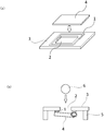
図1に、耐衝撃性試験装置の模式図を示す。
耐衝撃性試験装置は、以下の手順で作製した。
まず、上記で得られた両面粘着テープを外径が幅15.0mm、長さ15.0mm、内径が幅13.6mm、長さ13.6mmになるように打ち抜き、各枠辺の幅0.7mmとした四角枠状の試験片1を作製した。
次いで、図1(a)に示すように、中央に方形の孔2を設けたマグネシウム製被着板3を用意し、離型紙を剥がした試験片1を、マグネシウム製被着板3の上表面で、この孔2の外周側全周に亘って貼り付けた。
次いで、前記の孔2を被覆するサイズのガラス製被着板4を、試験片1の上に重ねて貼り付け、前記の孔2を被覆して耐衝撃性試験装置を組み立てた。
その後、耐衝撃性試験装置を上下反転して、マグネシウム製被着板3を上面にした状態で、マグネシウム製被着板3側から5kgfの圧力を5秒間加えて、上下に位置するマグネシウム製被着板3と試験片とを圧着し、常温で36時間放置した。
図1(b)に示すように、作製した耐衝撃性試験装置を支持台5に固定し、マグネシウム製被着板3に形成された孔2を通過する大きさの50gの重さの鉄球6を、孔2を通過するように落とした。鉄球を落とす高さを徐々に高くしていき、鉄球の落下により加わった衝撃により試験片と被着板が剥がれた時の鉄球を落した高さを計測し、耐衝撃性を評価した。高さが50cmより大きい場合を“S”、25cm以上50cm以下の場合を“A”、25cm未満の場合を“B”と評価した。
(層間強度測定用サンプルの作製)
図2に示すように、発泡シート7の25mm角範囲にプライマー(セメダイン株式会社製「PPXプライマー」)を塗布した後、塗布部分の中央に直径5mm分の接着剤8(セメダイン株式会社製「PPX」)を滴下した。その後直ちに、接着剤滴下部分に25mm角のアルミ製の治具9を置き、発泡シート7と治具9とを接着剤8により圧着した。その後、治具9の大きさに沿って発泡シートをカットした。カットした発泡シート7の治具9を接着していない面にプライマーを塗布し、塗布部分の中央に直径5mm分の接着剤10を滴下した。その後直ちに、接着剤滴下部分に10mm角のアルミ製の治具11を置き、発泡シート7と治具11とを接着剤10により圧着した。治具11の周辺にはみ出した接着剤をふき取った後、治具11の大きさに沿って発泡シートに切り込み12を入れた。これを室温で30分間放置することで接着剤を養生し、層間強度測定用サンプルとした。
(層間強度の判定)
続いて、1kNのロードセルを設置した試験機(株式会社エー・アンド・デイ製「テンシロン万能材料試験機」)に、発泡シート7のシート面が引張方向に対して垂直になるように層間強度測定用サンプルを取り付けた。治具9を速度100mm/分で垂直上向きに引っ張り、発泡シートの1cm角の範囲のみを層間剥離させた。このときの最大荷重を測定し、1回目の測定結果とした。同様の操作を3回繰り返し、その平均値を層間強度とした。層間強度が4.8MPa以上の場合を層間強度が優れるとして“A”とした。また、層間強度が4.3MPa以上4.8MPa未満の場合を層間強度が良好であるとして“B”とした。また、層間強度が4.3MPa未満の場合を層間強度が不十分であるとして“C”とした。
発泡シートについてJIS K6767に準拠して25%圧縮強度を測定した。
メタロセン化合物の重合触媒によって得られた直鎖状低密度ポリエチレン100質量部と、熱分解型発泡剤としてアゾジカルボンアミド2.1質量部と、気泡核調整剤として酸化亜鉛1.0質量部と、酸化防止剤0.5質量部とを押出機に供給して130℃で溶融混練し、厚さが290μmの長尺状の樹脂シートに押出した。
なお、上記直鎖状低密度ポリエチレンとしては、ダウケミカル社製の商品名「アフィニティーPL1850」(密度:0.902g/cm3)を用いた。また、上記酸化亜鉛としては、堺化学工業株式会社製の商品名「OW-212F」を用いた。
次に、上記長尺状の樹脂シートの両面に加速電圧500kVの電子線を7.4Mrad照射して樹脂シートを架橋した後、架橋した樹脂シートを熱風及び赤外線ヒーターにより250℃に保持された発泡炉内に連続的に送り込んで加熱して発泡させて、厚さ300μmの発泡シートを得た。
次いで、得られた発泡シートを発泡炉から連続的に送り出した後、この発泡シートをその両面の温度が200~250℃となるように維持した状態で次のように延伸させた。発泡シートをそのTD方向に2.0倍の延伸倍率で延伸させると共に、樹脂シートの発泡炉への送り込み速度(供給速度)よりも速い巻取速度でもって発泡シートを巻き取ることによって発泡シートをMD方向に延伸させて、冷却水を通した金属ロールの周面に接触させた。このようにして、発泡シートの気泡をTD方向及びMD方向に延伸して変形させ発泡シートを得た。なお、上記発泡シートの巻取速度は、樹脂シート自身の発泡によるMD方向への膨張分を考慮しつつ調整した。得られた発泡シートを上記評価方法に従って評価し、その結果を表1に示す。
実施例1の樹脂に代えて、樹脂の組成を直鎖状低密度ポリエチレン(ダウケミカル社製、商品名「アフィニティーPL1850」、密度:0.902g/cm3)30質量部、及びエチレン-酢酸ビニル共重合体(東ソー株式会社製、商品名「ウルトラセン636」)70質量部とした。また、発泡性組成物におけるアゾジカルボンアミドの配合量を1.9質量部とした。これら以外は、実施例1と同様に実施した。得られた発泡シートの評価結果を表1に示す。
発泡性組成物におけるアゾジカルボンアミドの配合量を2.5質量部とするとともに、電子線照射量を9.0Mradとして、架橋度を57.0質量%とした点を除いて実施例1と同様に実施した。得られた発泡シートの評価結果を表1に示す。
発泡性組成物におけるアゾジカルボンアミドの配合量を1.6質量部とするとともに、電子線照射量を4.7Mradとして、架橋度を16.2質量%とした点を除いて実施例1と同様に実施した。得られた発泡シートの評価結果を表1に示す。
実施例1の樹脂に代えて、樹脂の組成を直鎖状低密度ポリエチレン(ダウケミカル社製、商品名「アフィニティーPL1850」、密度:0.902g/cm3)30質量部、及びエチレン-酢酸ビニル共重合体(東ソー株式会社製、商品名「ウルトラセン636」)70質量部とした。また、発泡性組成物におけるアゾジカルボンアミドの配合量を1.5質量部とするとともに、電子線の照射量を4.7Mradとして、架橋度を19.2質量%とした。これら以外は、実施例1と同様に実施した。得られた発泡シートの評価結果を表1に示す。
比較例1で得られた発泡シートの両面に加速電圧500kVの電子線を7.4Mrad照射して発泡シートを架橋し、架橋度を71.0質量%とした。得られた発泡シートの評価結果を表1に示す。

2 孔
3 マグネシウム製被着板
4 ガラス製被着板
5 支持台
6 鉄球
7 発泡シート
8 接着剤
9 治具
10 接着剤
11 治具
12 切り込み
Claims (10)
- ポリオレフィン樹脂を含み、かつ架橋された発泡性組成物を発泡させてなるポリオレフィン系発泡シートであって、前記発泡性組成物における架橋点間平均分子量が15000~30000であるポリオレフィン系発泡シート。
- 前記ポリオレフィン樹脂がポリエチレン樹脂である、請求項1に記載のポリオレフィン系発泡シート。
- 前記ポリオレフィン樹脂が、メタロセン化合物の重合触媒で重合された直鎖状低密度ポリエチレンである、請求項2に記載のポリオレフィン系発泡シート。
- 架橋度が20~70質量%である、請求項1~3のいずれか1項に記載のポリオレフィン系発泡シート。
- 耐衝撃性評価結果が25~50cmの範囲にあるとともに、25%圧縮強度が10~2,000kPaである、請求項1~4のいずれか1項に記載のポリオレフィン系発泡シート。
- 厚さが0.02~0.8mmである、請求項1~5のいずれか1項に記載のポリオレフィン系発泡シート。
- 発泡倍率が1.2~8cm3/gである、請求項1~6のいずれか1項に記載のポリオレフィン系発泡シート。
- 熱分解型発泡剤をさらに含む発泡性組成物を発泡させてなる請求項1~7のいずれか1項に記載のポリオレフィン系発泡シート。
- 請求項1~8のいずれか1項に記載のポリオレフィン系発泡シートの製造方法であって、
ポリオレフィン樹脂及び熱分解型発泡剤を含み、かつ架橋された発泡性組成物を加熱し、前記熱分解型発泡剤を発泡させるポリオレフィン系発泡シートの製造方法。 - 請求項1~8のいずれか1項に記載のポリオレフィン系発泡シートと、前記ポリオレフィン系発泡シートの少なくともいずれか一方の面に設けた粘着剤層とを備える粘着テープ。
Priority Applications (3)
| Application Number | Priority Date | Filing Date | Title |
|---|---|---|---|
| KR1020187025039A KR102526579B1 (ko) | 2016-09-30 | 2017-09-29 | 폴리올레핀계 발포 시트, 그 제조 방법 및 점착 테이프 |
| CN201780014835.4A CN108699276A (zh) | 2016-09-30 | 2017-09-29 | 聚烯烃系发泡片材、其制造方法及粘合带 |
| JP2017553283A JP6918701B2 (ja) | 2016-09-30 | 2017-09-29 | ポリオレフィン系発泡シート、その製造方法及び粘着テープ |
Applications Claiming Priority (2)
| Application Number | Priority Date | Filing Date | Title |
|---|---|---|---|
| JP2016194858 | 2016-09-30 | ||
| JP2016-194858 | 2016-09-30 |
Publications (1)
| Publication Number | Publication Date |
|---|---|
| WO2018062514A1 true WO2018062514A1 (ja) | 2018-04-05 |
Family
ID=61760746
Family Applications (1)
| Application Number | Title | Priority Date | Filing Date |
|---|---|---|---|
| PCT/JP2017/035566 Ceased WO2018062514A1 (ja) | 2016-09-30 | 2017-09-29 | ポリオレフィン系発泡シート、その製造方法及び粘着テープ |
Country Status (5)
| Country | Link |
|---|---|
| JP (1) | JP6918701B2 (ja) |
| KR (1) | KR102526579B1 (ja) |
| CN (1) | CN108699276A (ja) |
| TW (1) | TWI752092B (ja) |
| WO (1) | WO2018062514A1 (ja) |
Cited By (1)
| Publication number | Priority date | Publication date | Assignee | Title |
|---|---|---|---|---|
| JP2021031608A (ja) * | 2019-08-27 | 2021-03-01 | 積水化学工業株式会社 | 発泡体シート、及び粘着テープ |
Families Citing this family (1)
| Publication number | Priority date | Publication date | Assignee | Title |
|---|---|---|---|---|
| CN112759813B (zh) * | 2020-12-30 | 2023-12-26 | 广德祥源新材科技有限公司 | 交联聚烯烃发泡片材及其制备方法 |
Citations (6)
| Publication number | Priority date | Publication date | Assignee | Title |
|---|---|---|---|---|
| JPH0848836A (ja) * | 1994-08-10 | 1996-02-20 | Mitsui Toatsu Chem Inc | ポリプロピレン樹脂組成物 |
| JPH1160776A (ja) * | 1997-08-26 | 1999-03-05 | Jsp Corp | ポリプロピレン系樹脂発泡体の製造方法及びポリプロピレン系樹脂発泡体 |
| JPH11140332A (ja) * | 1997-11-10 | 1999-05-25 | Tosoh Corp | 熱可塑性樹脂組成物 |
| WO2013018171A1 (ja) * | 2011-07-29 | 2013-02-07 | 電気化学工業株式会社 | 表皮材シート |
| JP2013053179A (ja) * | 2011-08-31 | 2013-03-21 | Sekisui Chem Co Ltd | 架橋ポリオレフィン樹脂発泡シート、粘着テープ及びシール材 |
| JP2013213104A (ja) * | 2012-03-30 | 2013-10-17 | Sekisui Chem Co Ltd | 架橋ポリオレフィン樹脂発泡シート |
Family Cites Families (5)
| Publication number | Priority date | Publication date | Assignee | Title |
|---|---|---|---|---|
| KR100563253B1 (ko) | 2003-07-11 | 2006-03-27 | 한국과학기술원 | 미소간극 내 자기장을 이용한 탄소나노튜브 정렬방법과이를 이용한 탄소나노튜브 팁 제작방법 |
| US10125201B2 (en) * | 2014-09-30 | 2018-11-13 | Sekisui Chemical Co., Ltd. | Polyolefin resin foam sheet and adhesive tape |
| US10174178B2 (en) * | 2014-09-30 | 2019-01-08 | Sekisui Chemical Co., Ltd. | Polyolefin resin foam sheet and adhesive tape |
| KR102062297B1 (ko) * | 2016-03-31 | 2020-01-03 | 세키스이가가쿠 고교가부시키가이샤 | 가교 폴리올레핀 수지 발포 시트 및 그 제조 방법 |
| WO2017171068A1 (ja) * | 2016-03-31 | 2017-10-05 | 積水化学工業株式会社 | 架橋ポリオレフィン樹脂発泡シート及びその製造方法 |
-
2017
- 2017-09-29 WO PCT/JP2017/035566 patent/WO2018062514A1/ja not_active Ceased
- 2017-09-29 KR KR1020187025039A patent/KR102526579B1/ko active Active
- 2017-09-29 JP JP2017553283A patent/JP6918701B2/ja active Active
- 2017-09-29 TW TW106133969A patent/TWI752092B/zh active
- 2017-09-29 CN CN201780014835.4A patent/CN108699276A/zh active Pending
Patent Citations (6)
| Publication number | Priority date | Publication date | Assignee | Title |
|---|---|---|---|---|
| JPH0848836A (ja) * | 1994-08-10 | 1996-02-20 | Mitsui Toatsu Chem Inc | ポリプロピレン樹脂組成物 |
| JPH1160776A (ja) * | 1997-08-26 | 1999-03-05 | Jsp Corp | ポリプロピレン系樹脂発泡体の製造方法及びポリプロピレン系樹脂発泡体 |
| JPH11140332A (ja) * | 1997-11-10 | 1999-05-25 | Tosoh Corp | 熱可塑性樹脂組成物 |
| WO2013018171A1 (ja) * | 2011-07-29 | 2013-02-07 | 電気化学工業株式会社 | 表皮材シート |
| JP2013053179A (ja) * | 2011-08-31 | 2013-03-21 | Sekisui Chem Co Ltd | 架橋ポリオレフィン樹脂発泡シート、粘着テープ及びシール材 |
| JP2013213104A (ja) * | 2012-03-30 | 2013-10-17 | Sekisui Chem Co Ltd | 架橋ポリオレフィン樹脂発泡シート |
Cited By (1)
| Publication number | Priority date | Publication date | Assignee | Title |
|---|---|---|---|---|
| JP2021031608A (ja) * | 2019-08-27 | 2021-03-01 | 積水化学工業株式会社 | 発泡体シート、及び粘着テープ |
Also Published As
| Publication number | Publication date |
|---|---|
| KR20190065185A (ko) | 2019-06-11 |
| CN108699276A (zh) | 2018-10-23 |
| TWI752092B (zh) | 2022-01-11 |
| JPWO2018062514A1 (ja) | 2019-07-11 |
| JP6918701B2 (ja) | 2021-08-11 |
| KR102526579B1 (ko) | 2023-04-28 |
| TW201817787A (zh) | 2018-05-16 |
Similar Documents
| Publication | Publication Date | Title |
|---|---|---|
| JP6672439B2 (ja) | ポリオレフィン系樹脂発泡シート及び粘着テープ | |
| JP6379040B2 (ja) | 架橋ポリオレフィン系樹脂発泡シート | |
| JP2020147757A (ja) | ポリオレフィン系樹脂発泡シート及び粘着テープ | |
| KR102557823B1 (ko) | 수지 발포 시트, 수지 발포 시트의 제조 방법, 및 점착 테이프 | |
| JP6496407B2 (ja) | 架橋ポリオレフィン樹脂発泡シート及びその製造方法 | |
| JP6918701B2 (ja) | ポリオレフィン系発泡シート、その製造方法及び粘着テープ | |
| JP6625032B2 (ja) | 独立気泡樹脂発泡体及びその製造方法 | |
| JP6901476B2 (ja) | 架橋樹脂発泡シート、その製造方法、及び粘着テープ | |
| JP2018172643A (ja) | 発泡シート、及び粘着テープ | |
| JP6572307B2 (ja) | 架橋ポリオレフィン樹脂発泡シート及びその製造方法 | |
| JP2023033396A (ja) | 樹脂発泡シート及び粘着テープ | |
| WO2018181498A1 (ja) | ポリオレフィン系発泡シート、その製造方法及び粘着テープ | |
| JP7063566B2 (ja) | 樹脂発泡シート、樹脂発泡シートの製造方法、及び粘着テープ | |
| JP6789053B2 (ja) | 樹脂発泡シート、樹脂発泡シートの製造方法、及び粘着テープ | |
| JP2020023723A (ja) | 独立気泡樹脂発泡体及びその製造方法 |
Legal Events
| Date | Code | Title | Description |
|---|---|---|---|
| WWE | Wipo information: entry into national phase |
Ref document number: 2017553283 Country of ref document: JP |
|
| ENP | Entry into the national phase |
Ref document number: 20187025039 Country of ref document: KR Kind code of ref document: A |
|
| 121 | Ep: the epo has been informed by wipo that ep was designated in this application |
Ref document number: 17856461 Country of ref document: EP Kind code of ref document: A1 |
|
| NENP | Non-entry into the national phase |
Ref country code: DE |
|
| 122 | Ep: pct application non-entry in european phase |
Ref document number: 17856461 Country of ref document: EP Kind code of ref document: A1 |