WO2018056346A1 - 基板処理装置、液体原料補充システム、半導体装置の製造方法、プログラム - Google Patents
基板処理装置、液体原料補充システム、半導体装置の製造方法、プログラム Download PDFInfo
- Publication number
- WO2018056346A1 WO2018056346A1 PCT/JP2017/034050 JP2017034050W WO2018056346A1 WO 2018056346 A1 WO2018056346 A1 WO 2018056346A1 JP 2017034050 W JP2017034050 W JP 2017034050W WO 2018056346 A1 WO2018056346 A1 WO 2018056346A1
- Authority
- WO
- WIPO (PCT)
- Prior art keywords
- liquid
- storage tank
- raw material
- gas
- level
- Prior art date
- Legal status (The legal status is an assumption and is not a legal conclusion. Google has not performed a legal analysis and makes no representation as to the accuracy of the status listed.)
- Ceased
Links
Images



Classifications
-
- H—ELECTRICITY
- H10—SEMICONDUCTOR DEVICES; ELECTRIC SOLID-STATE DEVICES NOT OTHERWISE PROVIDED FOR
- H10P—GENERIC PROCESSES OR APPARATUS FOR THE MANUFACTURE OR TREATMENT OF DEVICES COVERED BY CLASS H10
- H10P72/00—Handling or holding of wafers, substrates or devices during manufacture or treatment thereof
- H10P72/04—Apparatus for manufacture or treatment
- H10P72/0402—Apparatus for fluid treatment
-
- C—CHEMISTRY; METALLURGY
- C23—COATING METALLIC MATERIAL; COATING MATERIAL WITH METALLIC MATERIAL; CHEMICAL SURFACE TREATMENT; DIFFUSION TREATMENT OF METALLIC MATERIAL; COATING BY VACUUM EVAPORATION, BY SPUTTERING, BY ION IMPLANTATION OR BY CHEMICAL VAPOUR DEPOSITION, IN GENERAL; INHIBITING CORROSION OF METALLIC MATERIAL OR INCRUSTATION IN GENERAL
- C23C—COATING METALLIC MATERIAL; COATING MATERIAL WITH METALLIC MATERIAL; SURFACE TREATMENT OF METALLIC MATERIAL BY DIFFUSION INTO THE SURFACE, BY CHEMICAL CONVERSION OR SUBSTITUTION; COATING BY VACUUM EVAPORATION, BY SPUTTERING, BY ION IMPLANTATION OR BY CHEMICAL VAPOUR DEPOSITION, IN GENERAL
- C23C16/00—Chemical coating by decomposition of gaseous compounds, without leaving reaction products of surface material in the coating, i.e. chemical vapour deposition [CVD] processes
- C23C16/44—Chemical coating by decomposition of gaseous compounds, without leaving reaction products of surface material in the coating, i.e. chemical vapour deposition [CVD] processes characterised by the method of coating
- C23C16/455—Chemical coating by decomposition of gaseous compounds, without leaving reaction products of surface material in the coating, i.e. chemical vapour deposition [CVD] processes characterised by the method of coating characterised by the method used for introducing gases into reaction chamber or for modifying gas flows in reaction chamber
- C23C16/45523—Pulsed gas flow or change of composition over time
- C23C16/45525—Atomic layer deposition [ALD]
- C23C16/45544—Atomic layer deposition [ALD] characterized by the apparatus
-
- C—CHEMISTRY; METALLURGY
- C23—COATING METALLIC MATERIAL; COATING MATERIAL WITH METALLIC MATERIAL; CHEMICAL SURFACE TREATMENT; DIFFUSION TREATMENT OF METALLIC MATERIAL; COATING BY VACUUM EVAPORATION, BY SPUTTERING, BY ION IMPLANTATION OR BY CHEMICAL VAPOUR DEPOSITION, IN GENERAL; INHIBITING CORROSION OF METALLIC MATERIAL OR INCRUSTATION IN GENERAL
- C23C—COATING METALLIC MATERIAL; COATING MATERIAL WITH METALLIC MATERIAL; SURFACE TREATMENT OF METALLIC MATERIAL BY DIFFUSION INTO THE SURFACE, BY CHEMICAL CONVERSION OR SUBSTITUTION; COATING BY VACUUM EVAPORATION, BY SPUTTERING, BY ION IMPLANTATION OR BY CHEMICAL VAPOUR DEPOSITION, IN GENERAL
- C23C16/00—Chemical coating by decomposition of gaseous compounds, without leaving reaction products of surface material in the coating, i.e. chemical vapour deposition [CVD] processes
- C23C16/22—Chemical coating by decomposition of gaseous compounds, without leaving reaction products of surface material in the coating, i.e. chemical vapour deposition [CVD] processes characterised by the deposition of inorganic material, other than metallic material
- C23C16/30—Deposition of compounds, mixtures or solid solutions, e.g. borides, carbides, nitrides
- C23C16/40—Oxides
- C23C16/403—Oxides of aluminium, magnesium or beryllium
-
- C—CHEMISTRY; METALLURGY
- C23—COATING METALLIC MATERIAL; COATING MATERIAL WITH METALLIC MATERIAL; CHEMICAL SURFACE TREATMENT; DIFFUSION TREATMENT OF METALLIC MATERIAL; COATING BY VACUUM EVAPORATION, BY SPUTTERING, BY ION IMPLANTATION OR BY CHEMICAL VAPOUR DEPOSITION, IN GENERAL; INHIBITING CORROSION OF METALLIC MATERIAL OR INCRUSTATION IN GENERAL
- C23C—COATING METALLIC MATERIAL; COATING MATERIAL WITH METALLIC MATERIAL; SURFACE TREATMENT OF METALLIC MATERIAL BY DIFFUSION INTO THE SURFACE, BY CHEMICAL CONVERSION OR SUBSTITUTION; COATING BY VACUUM EVAPORATION, BY SPUTTERING, BY ION IMPLANTATION OR BY CHEMICAL VAPOUR DEPOSITION, IN GENERAL
- C23C16/00—Chemical coating by decomposition of gaseous compounds, without leaving reaction products of surface material in the coating, i.e. chemical vapour deposition [CVD] processes
- C23C16/44—Chemical coating by decomposition of gaseous compounds, without leaving reaction products of surface material in the coating, i.e. chemical vapour deposition [CVD] processes characterised by the method of coating
- C23C16/448—Chemical coating by decomposition of gaseous compounds, without leaving reaction products of surface material in the coating, i.e. chemical vapour deposition [CVD] processes characterised by the method of coating characterised by the method used for generating reactive gas streams, e.g. by evaporation or sublimation of precursor materials
-
- C—CHEMISTRY; METALLURGY
- C23—COATING METALLIC MATERIAL; COATING MATERIAL WITH METALLIC MATERIAL; CHEMICAL SURFACE TREATMENT; DIFFUSION TREATMENT OF METALLIC MATERIAL; COATING BY VACUUM EVAPORATION, BY SPUTTERING, BY ION IMPLANTATION OR BY CHEMICAL VAPOUR DEPOSITION, IN GENERAL; INHIBITING CORROSION OF METALLIC MATERIAL OR INCRUSTATION IN GENERAL
- C23C—COATING METALLIC MATERIAL; COATING MATERIAL WITH METALLIC MATERIAL; SURFACE TREATMENT OF METALLIC MATERIAL BY DIFFUSION INTO THE SURFACE, BY CHEMICAL CONVERSION OR SUBSTITUTION; COATING BY VACUUM EVAPORATION, BY SPUTTERING, BY ION IMPLANTATION OR BY CHEMICAL VAPOUR DEPOSITION, IN GENERAL
- C23C16/00—Chemical coating by decomposition of gaseous compounds, without leaving reaction products of surface material in the coating, i.e. chemical vapour deposition [CVD] processes
- C23C16/44—Chemical coating by decomposition of gaseous compounds, without leaving reaction products of surface material in the coating, i.e. chemical vapour deposition [CVD] processes characterised by the method of coating
- C23C16/448—Chemical coating by decomposition of gaseous compounds, without leaving reaction products of surface material in the coating, i.e. chemical vapour deposition [CVD] processes characterised by the method of coating characterised by the method used for generating reactive gas streams, e.g. by evaporation or sublimation of precursor materials
- C23C16/4481—Chemical coating by decomposition of gaseous compounds, without leaving reaction products of surface material in the coating, i.e. chemical vapour deposition [CVD] processes characterised by the method of coating characterised by the method used for generating reactive gas streams, e.g. by evaporation or sublimation of precursor materials by evaporation using carrier gas in contact with the source material
- C23C16/4482—Chemical coating by decomposition of gaseous compounds, without leaving reaction products of surface material in the coating, i.e. chemical vapour deposition [CVD] processes characterised by the method of coating characterised by the method used for generating reactive gas streams, e.g. by evaporation or sublimation of precursor materials by evaporation using carrier gas in contact with the source material by bubbling of carrier gas through liquid source material
-
- C—CHEMISTRY; METALLURGY
- C23—COATING METALLIC MATERIAL; COATING MATERIAL WITH METALLIC MATERIAL; CHEMICAL SURFACE TREATMENT; DIFFUSION TREATMENT OF METALLIC MATERIAL; COATING BY VACUUM EVAPORATION, BY SPUTTERING, BY ION IMPLANTATION OR BY CHEMICAL VAPOUR DEPOSITION, IN GENERAL; INHIBITING CORROSION OF METALLIC MATERIAL OR INCRUSTATION IN GENERAL
- C23C—COATING METALLIC MATERIAL; COATING MATERIAL WITH METALLIC MATERIAL; SURFACE TREATMENT OF METALLIC MATERIAL BY DIFFUSION INTO THE SURFACE, BY CHEMICAL CONVERSION OR SUBSTITUTION; COATING BY VACUUM EVAPORATION, BY SPUTTERING, BY ION IMPLANTATION OR BY CHEMICAL VAPOUR DEPOSITION, IN GENERAL
- C23C16/00—Chemical coating by decomposition of gaseous compounds, without leaving reaction products of surface material in the coating, i.e. chemical vapour deposition [CVD] processes
- C23C16/44—Chemical coating by decomposition of gaseous compounds, without leaving reaction products of surface material in the coating, i.e. chemical vapour deposition [CVD] processes characterised by the method of coating
- C23C16/455—Chemical coating by decomposition of gaseous compounds, without leaving reaction products of surface material in the coating, i.e. chemical vapour deposition [CVD] processes characterised by the method of coating characterised by the method used for introducing gases into reaction chamber or for modifying gas flows in reaction chamber
- C23C16/45523—Pulsed gas flow or change of composition over time
-
- C—CHEMISTRY; METALLURGY
- C23—COATING METALLIC MATERIAL; COATING MATERIAL WITH METALLIC MATERIAL; CHEMICAL SURFACE TREATMENT; DIFFUSION TREATMENT OF METALLIC MATERIAL; COATING BY VACUUM EVAPORATION, BY SPUTTERING, BY ION IMPLANTATION OR BY CHEMICAL VAPOUR DEPOSITION, IN GENERAL; INHIBITING CORROSION OF METALLIC MATERIAL OR INCRUSTATION IN GENERAL
- C23C—COATING METALLIC MATERIAL; COATING MATERIAL WITH METALLIC MATERIAL; SURFACE TREATMENT OF METALLIC MATERIAL BY DIFFUSION INTO THE SURFACE, BY CHEMICAL CONVERSION OR SUBSTITUTION; COATING BY VACUUM EVAPORATION, BY SPUTTERING, BY ION IMPLANTATION OR BY CHEMICAL VAPOUR DEPOSITION, IN GENERAL
- C23C16/00—Chemical coating by decomposition of gaseous compounds, without leaving reaction products of surface material in the coating, i.e. chemical vapour deposition [CVD] processes
- C23C16/44—Chemical coating by decomposition of gaseous compounds, without leaving reaction products of surface material in the coating, i.e. chemical vapour deposition [CVD] processes characterised by the method of coating
- C23C16/46—Chemical coating by decomposition of gaseous compounds, without leaving reaction products of surface material in the coating, i.e. chemical vapour deposition [CVD] processes characterised by the method of coating characterised by the method used for heating the substrate
-
- C—CHEMISTRY; METALLURGY
- C23—COATING METALLIC MATERIAL; COATING MATERIAL WITH METALLIC MATERIAL; CHEMICAL SURFACE TREATMENT; DIFFUSION TREATMENT OF METALLIC MATERIAL; COATING BY VACUUM EVAPORATION, BY SPUTTERING, BY ION IMPLANTATION OR BY CHEMICAL VAPOUR DEPOSITION, IN GENERAL; INHIBITING CORROSION OF METALLIC MATERIAL OR INCRUSTATION IN GENERAL
- C23C—COATING METALLIC MATERIAL; COATING MATERIAL WITH METALLIC MATERIAL; SURFACE TREATMENT OF METALLIC MATERIAL BY DIFFUSION INTO THE SURFACE, BY CHEMICAL CONVERSION OR SUBSTITUTION; COATING BY VACUUM EVAPORATION, BY SPUTTERING, BY ION IMPLANTATION OR BY CHEMICAL VAPOUR DEPOSITION, IN GENERAL
- C23C16/00—Chemical coating by decomposition of gaseous compounds, without leaving reaction products of surface material in the coating, i.e. chemical vapour deposition [CVD] processes
- C23C16/44—Chemical coating by decomposition of gaseous compounds, without leaving reaction products of surface material in the coating, i.e. chemical vapour deposition [CVD] processes characterised by the method of coating
- C23C16/52—Controlling or regulating the coating process
-
- H—ELECTRICITY
- H10—SEMICONDUCTOR DEVICES; ELECTRIC SOLID-STATE DEVICES NOT OTHERWISE PROVIDED FOR
- H10P—GENERIC PROCESSES OR APPARATUS FOR THE MANUFACTURE OR TREATMENT OF DEVICES COVERED BY CLASS H10
- H10P14/00—Formation of materials, e.g. in the shape of layers or pillars
- H10P14/60—Formation of materials, e.g. in the shape of layers or pillars of insulating materials
- H10P14/63—Formation of materials, e.g. in the shape of layers or pillars of insulating materials characterised by the formation processes
- H10P14/6326—Deposition processes
- H10P14/6328—Deposition from the gas or vapour phase
- H10P14/6334—Deposition from the gas or vapour phase using decomposition or reaction of gaseous or vapour phase compounds, i.e. chemical vapour deposition
- H10P14/6339—Deposition from the gas or vapour phase using decomposition or reaction of gaseous or vapour phase compounds, i.e. chemical vapour deposition deposition by cyclic CVD, e.g. ALD, ALE or pulsed CVD
-
- H—ELECTRICITY
- H10—SEMICONDUCTOR DEVICES; ELECTRIC SOLID-STATE DEVICES NOT OTHERWISE PROVIDED FOR
- H10P—GENERIC PROCESSES OR APPARATUS FOR THE MANUFACTURE OR TREATMENT OF DEVICES COVERED BY CLASS H10
- H10P14/00—Formation of materials, e.g. in the shape of layers or pillars
- H10P14/60—Formation of materials, e.g. in the shape of layers or pillars of insulating materials
- H10P14/69—Inorganic materials
- H10P14/692—Inorganic materials composed of oxides, glassy oxides or oxide-based glasses
- H10P14/6938—Inorganic materials composed of oxides, glassy oxides or oxide-based glasses the material containing at least one metal element, e.g. metal oxides, metal oxynitrides or metal oxycarbides
- H10P14/6939—Inorganic materials composed of oxides, glassy oxides or oxide-based glasses the material containing at least one metal element, e.g. metal oxides, metal oxynitrides or metal oxycarbides characterised by the metal
- H10P14/69391—Inorganic materials composed of oxides, glassy oxides or oxide-based glasses the material containing at least one metal element, e.g. metal oxides, metal oxynitrides or metal oxycarbides characterised by the metal the material containing aluminium, e.g. Al2O3
-
- H—ELECTRICITY
- H10—SEMICONDUCTOR DEVICES; ELECTRIC SOLID-STATE DEVICES NOT OTHERWISE PROVIDED FOR
- H10P—GENERIC PROCESSES OR APPARATUS FOR THE MANUFACTURE OR TREATMENT OF DEVICES COVERED BY CLASS H10
- H10P72/00—Handling or holding of wafers, substrates or devices during manufacture or treatment thereof
- H10P72/06—Apparatus for monitoring, sorting, marking, testing or measuring
- H10P72/0604—Process monitoring, e.g. flow or thickness monitoring
-
- H—ELECTRICITY
- H10—SEMICONDUCTOR DEVICES; ELECTRIC SOLID-STATE DEVICES NOT OTHERWISE PROVIDED FOR
- H10P—GENERIC PROCESSES OR APPARATUS FOR THE MANUFACTURE OR TREATMENT OF DEVICES COVERED BY CLASS H10
- H10P72/00—Handling or holding of wafers, substrates or devices during manufacture or treatment thereof
- H10P72/06—Apparatus for monitoring, sorting, marking, testing or measuring
- H10P72/0612—Production flow monitoring, e.g. for increasing throughput
Definitions
- the present invention relates to a substrate processing apparatus, a liquid material replenishment system, a semiconductor device manufacturing method, and a program.
- Patent Document 1 describes a film forming process for forming a film on a substrate housed in a processing chamber as one step of a semiconductor device (device) manufacturing process.
- a source gas for example, trimethylaluminum (Al (CH 3 ) 3 ) abbreviation: TMA
- TMA trimethylaluminum
- the source gas contains impurities at a ppb (parts per bill) level. Due to the amount of impurities, the in-plane uniformity value of the film formed on the substrate varies.
- An object of the present invention is to suppress variations in the in-plane uniformity value of a film formed on a substrate.
- the liquid raw material is stored including a processing section in which a processing chamber for accommodating a substrate is formed, a bottom portion having a concave recess, and a wall portion rising from a peripheral edge of the bottom portion.
- a storage tank a vaporization unit that vaporizes a liquid raw material stored in the storage tank to generate a raw material gas
- a supply unit that supplies the raw material gas generated by the vaporization unit to the processing chamber
- a sensor that continuously detects the liquid level of the liquid material stored in the storage tank and has a sensor element disposed in the recess, a replenishment unit that replenishes the storage tank with the liquid material, and the supply unit
- a control unit that controls the replenishment unit based on a surface level and replenishes the storage tank with the liquid material so that a liquid surface level of the liquid material stored in the storage tank becomes a
- the present inventors have earnestly studied the relationship between the amount of the liquid raw material stored in the storage tank and the in-plane uniformity of the film formed on the substrate by the raw material gas generated by vaporizing the liquid raw material. did. As a result, the present inventors have reached the present invention from the following findings.
- the present inventors have found that the concentration of impurities contained in the vaporized source gas changes according to the amount (remaining amount) of the liquid source stored in the storage tank. This is because the concentration of impurities contained in the vaporized source gas (TMA gas) changes according to the remaining amount of the liquid source (TMA) stored in the storage tank. That is, in any remaining amount, impurities are saturated in the liquid raw material, but the concentration is slightly changed.
- the in-plane uniformity value of the film formed on the substrate decreases.
- the in-plane uniformity value of the film formed on the substrate increases. That is, the in-plane uniformity value of the film formed on the substrate varies depending on the amount of the liquid raw material stored in the storage tank.
- In-plane uniformity refers to the following formula (1) using the maximum in-plane film thickness, the minimum in-plane film thickness, and the in-plane average film thickness in the film formed on the substrate. Is calculated by
- In-plane uniformity [(maximum in-plane film thickness ⁇ in-plane minimum film thickness) / (in-plane average film thickness ⁇ 2)] ⁇ 100 ( ⁇ %) (1)
- FIGS. 6A and 6B are graphs showing the relationship between the in-plane uniformity and the amount of the liquid raw material stored in the storage tank. 6A and 6B, the vertical axis represents the in-plane uniformity, and the horizontal axis represents the amount of the liquid material stored in the storage tank.
- FIG. 6A shows a film formed on the top (TOP) substrate among a plurality of substrates loaded on a boat (details will be described later), and FIG. 6B shows a film loaded on the boat. Among the plurality of substrates, a film formed on the lowest (BTM) substrate is shown.
- FIGS. 1-10 An example of a substrate processing apparatus, a liquid material replenishment system, a semiconductor device manufacturing method, and a program according to an embodiment of the present invention will be described with reference to FIGS.
- an arrow H indicates the vertical direction of the apparatus (vertical direction)
- an arrow W indicates the apparatus width direction (horizontal direction)
- an arrow D indicates the apparatus width direction (horizontal direction).
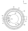
- the substrate processing apparatus 10 provided with the liquid source replenishment system 780 includes a processing furnace 202 for processing a wafer 200 as a substrate.
- the processing furnace 202 has a cylindrical heater 207 extending in the vertical direction of the apparatus, and the heater 207 is supported by a heater base (not shown) as a holding plate.
- the heater 207 heats the inside of the processing chamber 201 described later to a predetermined temperature.
- a processing tube 203 as a processing unit having a cylindrical shape concentric with the heater 207 is disposed inside the heater 207.
- the processing tube 203 is made of a heat-resistant material such as quartz (SiO 2 ) or silicon carbide (SiC), and has an upper end closed and a lower end opened.
- a processing chamber 201 for processing a plurality of wafers 200 is formed inside the processing tube 203. Specifically, a plurality of (for example, 25 to 200) wafers 200 are stacked in a vertical direction by a boat 217 as a substrate support, and the plurality of wafers 200 loaded by the boat 217 are processed in the processing chamber 201. Is disposed inside.
- the boat 217 is made of a heat resistant material such as quartz or SiC.
- a cylindrical heat insulating cylinder 218 made of a heat resistant material such as quartz or SiC is disposed below the boat 217. This configuration makes it difficult for heat from the heater 207 to be transmitted to the seal cap 219 side described later.
- a manifold (inlet flange) 209 having a cylindrical shape concentric with the processing tube 203 is disposed below the processing tube 203, as shown in FIG.
- the manifold 209 is made of a metal such as stainless steel (SUS) and has an upper end and a lower end opened.
- the upper end of the manifold 209 faces the lower end of the processing tube 203, and the manifold 209 supports the processing tube 203 via an O-ring 220 as a seal member.
- nozzles 410 and 420 extending in the vertical direction are disposed between the wall surface of the processing tube 203 and the plurality of wafers 200 loaded by the boat 217. Further, in the nozzles 410 and 420, a plurality of supply holes 410a and 420a for supplying gas are respectively formed in ranges that face the wafer 200 in the horizontal direction. As a result, the gas ejected from the supply holes 410 a and 420 a flows toward the wafer 200.
- the lower end portion of the nozzles 410 and 420 is bent and penetrates the side wall of the manifold 209, and the lower end portion of the nozzles 410 and 420 protrudes outside the manifold 209.
- Gas supply pipes 310 and 320 as gas supply lines are connected to the lower ends of the nozzles 410 and 420, respectively. As a result, a plurality of types of gases are supplied to the processing chamber 201.
- the gas supply pipes 310 and 320 include a mass flow controller (MFC) which is a flow rate controller (flow rate control unit) in order from the upstream side of the flow direction of gas flowing through the gas supply pipes 310 and 320 (hereinafter referred to as “gas flow direction”).
- MFC mass flow controller
- 312 and 322 and valves 314 and 324 as opening / closing valves are provided, respectively.
- the end portions of the gas supply pipes 510 and 520 as gas supply lines for supplying an inert gas are respectively provided on the downstream side of the valves 314 and 324 in the gas flow direction. It is connected.
- the gas supply pipes 510 and 520 are provided with MFCs 512 and 522 as flow rate controllers (flow rate control units) and valves 514 and 524 as opening / closing valves in order from the upstream side in the flow direction of the gas flowing through the gas supply pipes 510 and 520. Each is provided.
- a raw material gas as a processing gas is supplied to the processing chamber 201 through the MFC 312, the valve 314, and the nozzle 410.
- the supply unit 308 that supplies the source gas to the processing chamber 201 includes the gas supply pipe 310, the MFC 312, the valve 314, and the nozzle 410.
- TMA trimethylaluminum
- Al (CH 3 ) 3 abbreviation as an aluminum-containing source (Al-containing source gas, Al-containing gas) that is a metal-containing gas containing aluminum (Al), which is a metal element : TMA)
- Al-containing source gas Al-containing gas
- Al-containing gas metal-containing gas containing aluminum
- TMA is an organic material and is alkylaluminum in which an alkyl group is bonded as a ligand to aluminum.
- the raw material gas is a gaseous raw material, for example, a gaseous raw material that is in a gaseous state under normal temperature and normal pressure, or a gas obtained by vaporizing a liquid raw material that is in a liquid state under normal temperature and normal pressure.
- the source gas supply system When supplying the source gas that self-decomposes at a predetermined temperature from the gas supply pipe 310, the source gas supply system is mainly configured by the gas supply pipe 310, the MFC 312 and the valve 314.
- the nozzle 410 may be included in the source gas supply system.
- the source gas supply system can also be referred to as a source supply system.
- the source gas supply system When supplying the metal-containing gas from the gas supply pipe 310, the source gas supply system can also be referred to as a metal-containing gas supply system.
- the metal-containing gas supply system can also be referred to as an aluminum-containing raw material (Al-containing raw material gas, Al-containing gas) supply system.
- Al-containing raw material gas Al-containing gas
- TMA TMA supply system
- a reaction gas as a processing gas is supplied from the gas supply pipe 320 to the processing chamber 201 via the MFC 322, the valve 324, and the nozzle 420.
- the reaction gas for example, an oxygen-containing gas (oxidation gas, oxidant) is used as a reaction gas (reactant) containing oxygen (O) and reacting with Al.
- the reaction gas supply system (reactant supply system) is mainly configured by the gas supply pipe 320, the MFC 322, and the valve 324.
- the nozzle 420 may be included in the reaction gas supply system.
- the reaction gas supply system can also be referred to as an oxygen-containing gas (oxidizing gas, oxidant) supply system.
- O 3 oxygen-containing gas
- the oxygen-containing gas supply system can also be referred to as an O 3 supply system.
- the reaction gas is allowed to flow from the nozzle 420, the nozzle 420 may be referred to as a reaction gas nozzle.
- N 2 gas is used as the inert gas that is supplied from the gas supply pipes 510 and 520 to the processing chamber 201 through the MFCs 512 and 522, the valves 514 and 524, and the nozzles 410 and 420.
- the gas supply pipes 510 and 520, the MFCs 512 and 522, and the valves 514 and 325 constitute an inert gas supply system.
- an exhaust pipe 231 serving as an exhaust passage for exhausting the atmosphere of the processing chamber 201 is connected to the wall surface of the manifold 209.
- a pressure sensor 245 as a pressure detector (pressure detection unit) for detecting the pressure in the processing chamber 201 and an APC (Auto Pressure Controller) valve 243 as an exhaust valve (pressure adjustment unit) are attached to the exhaust pipe 231 for exhaust.
- a vacuum pump 246 as a vacuum exhaust device is attached to the end of the tube 231.
- the APC valve 243 can open and close the vacuum pump 246 while the vacuum pump 246 is operated, and can stop the vacuum exhaust and stop the vacuum exhaust of the processing chamber 201.
- the valve is configured so that the pressure in the processing chamber 201 can be adjusted by adjusting the valve opening based on the pressure information detected by the sensor 245.
- An exhaust system is mainly configured by the exhaust pipe 231, the APC valve 243, and the pressure sensor 245.
- the vacuum pump 246 may be included in the exhaust system.
- the exhaust pipe 231 is not limited to being provided in the processing pipe 203 but may be provided in the manifold 209 in the same manner as the nozzles 410 and 420.
- a seal cap 219 is provided as a furnace opening lid capable of airtightly closing the lower end opening of the manifold 209.
- the seal cap 219 is configured to contact the lower end of the manifold 209 from the lower side in the vertical direction.
- the seal cap 219 is made of a metal such as SUS and has a disk shape.
- an O-ring 220 is provided as a seal member that comes into contact with the lower end of the manifold 209.
- a rotation mechanism 267 for rotating a boat 217 described later is installed on the opposite side of the processing chamber 201 with respect to the seal cap 219.
- a rotation shaft 255 of the rotation mechanism 267 passes through the seal cap 219 and is connected to the boat 217.
- the rotation mechanism 267 is configured to rotate the wafer 200 by rotating the boat 217.
- the seal cap 219 is configured to be lifted and lowered in the vertical direction by a boat elevator 115 as a lifting mechanism vertically installed outside the processing tube 203.
- the boat elevator 115 is configured so that the boat 217 can be carried in and out of the processing chamber 201 by moving the seal cap 219 up and down.
- the boat elevator 115 is configured as a transfer device (transfer mechanism) that transfers the boat 217, that is, the wafers 200 into and out of the processing chamber 201.
- a shutter 219s is provided below the manifold 209 as a furnace port lid that can airtightly close the lower end opening of the manifold 209 while the seal cap 219 is lowered by the boat elevator 115.
- the shutter 219s is formed of a metal such as SUS and has a disk shape. On the upper surface of the shutter 219s, an O-ring 220c as a seal member that comes into contact with the lower end of the manifold 209 is provided.
- the opening / closing operation (elevating operation, rotating operation, etc.) of the shutter 219s is controlled by the shutter opening / closing mechanism 115s.
- the processing chamber 201 is provided with a temperature sensor 263 as a temperature detector.
- the temperature of the processing chamber 201 has a desired temperature distribution by adjusting the power supply to the heater 207 based on the temperature information detected by the temperature sensor 263.
- the temperature sensor 263 is provided along the inner wall of the processing tube 203 as with the nozzles 410 and 420.
- control unit 121 as the control unit provided in the substrate processing apparatus 10 will be described.
- the control unit 121 is configured as a computer having a CPU (Central Processing Unit) 121a, a RAM (Random Access Memory) 121b, a storage device 121c, and an I / O port 121d.
- the RAM 121b, the storage device 121c, and the I / O port 121d are configured to exchange data with the CPU 121a via the internal bus 121e.
- an input / output device 122 configured as a touch panel or the like is connected to the control unit 121.
- the storage device 121c includes, for example, a flash memory, a HDD (Hard Disk Drive), and the like.
- a control program or the like for controlling the operation of the substrate processing apparatus is stored in a readable manner.
- the RAM 121b is configured as a memory area (work area) in which a program or data read by the CPU 121a is temporarily stored.
- the I / O port 121d includes the aforementioned MFCs 512, 522, 312, 322, valves 514, 524, 314, 324, pressure sensor 245, APC valve 243, vacuum pump 246, temperature sensor 263, heater 207, rotating mechanism 267, boat It is connected to an elevator 115, a shutter opening / closing mechanism 115s, an ultrasonic sensor 650, an MFC 706, a valve 758, and the like which will be described later.
- the CPU 121a is configured to read and execute a control program from the storage device 121c and to read data from the storage device 121c in response to an operation command input from the input / output device 122 or the like.
- the CPU 121a adjusts the flow rates of various gases by the MFCs 512, 522, 312, and 322, the opening and closing operations of the valves 514, 524, 314, and 324, the opening and closing operations of the APC valve 243, and the pressure sensor 245 in accordance with the contents of the read data.
- the pressure adjustment operation by the APC valve 243 based on the above, the start and stop of the vacuum pump 246, the temperature adjustment operation of the heater 207 based on the temperature sensor 263, the rotation and rotation speed adjustment operation of the boat 217 by the rotation mechanism 267, the boat 217 by the boat elevator 115 And the opening / closing operation of the shutter 219s by the shutter opening / closing mechanism 115s.
- the control unit 121 is stored in an external storage device 123 (for example, a magnetic tape, a magnetic disk such as a flexible disk or a hard disk, an optical disk such as a CD or DVD, a magneto-optical disk such as an MO, or a semiconductor memory such as a USB memory or a memory card).
- an external storage device 123 for example, a magnetic tape, a magnetic disk such as a flexible disk or a hard disk, an optical disk such as a CD or DVD, a magneto-optical disk such as an MO, or a semiconductor memory such as a USB memory or a memory card.
- the storage device 121c and the external storage device 123 are configured as computer-readable recording media. Hereinafter, these are collectively referred to simply as a recording medium.
- recording medium When the term “recording medium” is used in this specification, it may include only the storage device 121c alone, may include only the external storage device 123 alone, or may include both of them.
- the program may be provided to the computer using a communication means such as the Internet or a dedicated line without using the external storage device 123.
- control of the ultrasonic sensor 650, the MFC 706, and the valve 758, which will be described later, by the control unit 121 will be described together with the operation described later.
- the storage tank 610 has a rectangular parallelepiped shape. Furthermore, as shown in FIG. 1, the storage space 612 formed inside the storage tank 610 is surrounded by the bottom portion 620, the plurality of wall portions 630 that rise from the periphery of the bottom portion 620, and the plurality of wall portions 630.
- the storage space 612 is formed by a ceiling portion 640 that closes the storage space 612 from above, and is a space sealed from the outside.
- the storage space 612 has a predetermined pressure. Furthermore, the lower end portion of the gas supply pipe 310 described above is disposed in the storage space 612 through the ceiling portion 640.
- the bottom portion 620 has a bottom surface 622 facing upward, and a concave portion 624 in which a part of the bottom surface 622 is recessed is formed in a portion of the bottom surface 622 on the center side in the apparatus width direction and the apparatus depth direction.
- the recess 624 extends in the vertical direction and has a rectangular cross section.
- the lower limit setting value (Low Setting) for the liquid material in the present embodiment is higher (larger) than the lower limit value (Low limit) at which the liquid material can be stored in the storage space 612 (see illustration).
- the upper limit setting value (High Setting) for the liquid material in the present embodiment is lower (smaller) than the upper limit value (High limit) at which the liquid material can be stored in the storage space 612 (see illustration). ).
- the lower limit set value is set higher than the lower limit that can be stored is that the raw material is insufficient even when film formation is performed from the lower limit value while achieving a lower limit at which the ultrasonic sensor 650 can accurately monitor the liquid level. This is to avoid this.
- the upper limit set value is set lower than the storable upper limit value so as not to affect the apparatus even if the upper limit set value is exceeded. ing.
- the upper limit set value is set to a use amount required for one film formation, batch refilling is performed. In some cases, two refills are required.
- the ultrasonic sensor 650 is disposed in the storage space 612 and extends in the vertical direction, and the upper end is attached to the ceiling portion 640.
- the cross-sectional shape of the ultrasonic sensor 650 is smaller than the cross-sectional shape of the recess 624.
- the lower part of the ultrasonic sensor 650 is disposed in the recess 624, and a sensor element 652 is attached to the lower end of the ultrasonic sensor 650.
- the ultrasonic wave generated by the sensor element 652 is reflected on the liquid surface of the liquid raw material, and the ultrasonic wave sensor 650 receives the reflected wave by a wave receiving unit (not shown) of the ultrasonic sensor 650, thereby The liquid level of the liquid raw material stored in the storage tank 610 is continuously detected.
- the ultrasonic sensor 650 functions as a continuous sensor (also referred to as a continuous sensor, a continuous level sensor, or a continuous liquid level sensor).
- the vaporization unit 700 is a device that vaporizes the liquid raw material stored in the storage tank 610 into a raw material gas by a bubbling method, and includes a gas supply pipe 704 through which a carrier gas flows, a mass flow controller (MFC) 706.
- MFC mass flow controller
- the gas supply pipe 704 penetrates the ceiling portion 640, and one end of the gas supply pipe 704 is disposed in the liquid raw material stored in the storage tank 610.
- the MFC 706 is provided in a portion of the gas supply pipe 704 disposed outside the storage tank 610.
- the carrier gas whose flow rate is adjusted by the MFC 706 is supplied to the liquid material from one end of the gas supply pipe 704. Then, the carrier gas acts on the liquid raw material to vaporize the liquid raw material.
- the supply amount of carrier gas (for example, N 2 gas) supplied to the storage tank 610 (bubbler) can be controlled, but the actual vaporization amount cannot be grasped. Therefore, in the present embodiment, the amount of vaporization is grasped by detecting the decrease amount of the liquid raw material using the ultrasonic sensor 650 described above.
- carrier gas for example, N 2 gas
- the replenishment unit 750 is a device that replenishes the storage tank 610 with a liquid material by a so-called automatic supply system (ARS: Auto Refill System), and includes a liquid supply pipe 754 through which the liquid material flows and an on-off valve. A valve 758 and a replenishment tank 760 in which the liquid material to be replenished is stored are provided.
- ARS Auto Refill System
- the liquid supply pipe 754 passes through the ceiling portion 640 and has one end disposed in the storage space 612.
- the replenishment tank 760 is disposed outside the storage tank 610 and connected to the other end of the liquid supply pipe 754.
- the valve 758 is provided in a portion of the liquid supply pipe 754 disposed outside the storage tank 610.
- the liquid material is always accumulated in the portion between the replenishing tank 760 and the valve 758 in the liquid supply pipe 754.
- the replenishing unit 750 replenishes the storage tank 610 with the liquid material by opening the closed valve 758.
- the processing chamber 201 accommodated in a state where a plurality of wafers 200 are stacked is heated at a predetermined temperature. Then, a raw material gas supply step of supplying TMA gas as a raw material gas from the supply hole 410a of the nozzle 410 to the processing chamber 201, a reactive gas supply step of supplying O 3 gas as a reactive gas from the supply hole 420a of the nozzle 420, Is performed a predetermined number of times (n times). Thereby, an aluminum oxide film (AlO film) is formed on the wafer 200 as a film containing Al and O.
- AlO film aluminum oxide film
- a plurality of wafers 200 are loaded on the boat 217 (wafer charge).
- the shutter 219s is moved by the shutter opening / closing mechanism 115s, and the lower end opening of the manifold 209 is opened (shutter open).
- the boat 217 loaded with a plurality of wafers 200 is lifted by the boat elevator 115 and loaded into the processing chamber 201 (boat loading).
- the seal cap 219 seals the lower end of the manifold 209 via the O-ring 220b.
- the processing chamber 201 is vacuum deaerated by the vacuum pump 246 so as to have a desired pressure (degree of vacuum).
- the pressure in the processing chamber 201 is measured by the pressure sensor 245, and the APC valve 243 is feedback-controlled based on the measured pressure information (pressure adjustment).
- the vacuum pump 246 keeps operating at least until the processing on the wafer 200 is completed.
- the processing chamber 201 is heated by the heater 207 so as to have a desired temperature.
- the energization amount to the heater 207 is feedback-controlled based on the temperature information detected by the temperature sensor 263 (see FIG. 2) so that the processing chamber 201 has a desired temperature distribution (temperature adjustment).
- the heating of the processing chamber 201 by the heater 207 is continuously performed at least until the processing on the wafer 200 is completed.
- the boat 217 and the wafer 200 are rotated by the rotation mechanism 267.
- the rotation of the boat 217 and the wafer 200 by the rotation mechanism 267 is continuously performed at least until the processing on the wafer 200 is completed.
- the storage tank is set so that the liquid level of the liquid raw material stored in the storage tank 610 shown in FIG. 1 becomes a predetermined initial liquid level.
- a liquid raw material is stored in 610.
- the initial liquid level is defined as the minimum amount of liquid raw material required for the ultrasonic sensor 650 to detect the liquid level and the number of times of film formation described later (1). It is the liquid level when the total amount of the liquid raw material required for performing the batch) is stored in the storage tank 610.
- the minimum amount of the liquid raw material required for the ultrasonic sensor 650 to detect the liquid level is an amount when the liquid level is located at the lower limit (Low limit) of the storage tank 610.
- the amount of liquid raw material required to perform the film forming process a predetermined number of times is determined in advance as a cycle in which a raw material gas supply process, a residual gas removal process, a reactive gas supply process, and a residual gas removal process, which will be described later, are performed in order. This is the amount required to form the AlO film on the wafer 200 by performing the given number of times (one or more times).
- the control unit 121 detects the liquid level of the liquid raw material using the ultrasonic sensor 650. When the liquid level of the liquid material does not reach the initial liquid level, the control unit 121 replenishes the storage tank 610 with the liquid material by opening the valve 758 that is closed. When the liquid level detected by the ultrasonic sensor 650 reaches the initial liquid level, the control unit 121 closes the opened valve 758 to adjust the liquid source amount. Terminate.
- the liquid material is not replenished to the storage tank 610 by the replenishing unit 750 so as to be higher than the initial liquid level. For this reason, first, the liquid level when the ultrasonic sensor 650 detects the liquid level of the liquid raw material is never higher than the initial liquid level.
- control unit 121 stores in advance the amount of source gas required in the source gas supply process described later, and the control unit 121 controls the MFC 706 of the vaporization unit 700 to be stored in the storage tank 610.
- the carrier gas is supplied to the liquid raw material. Thereby, the liquid raw material is vaporized into the raw material gas.
- the valve 314 shown in FIG. 3 is opened, and the raw material gas (TMA gas) is caused to flow into the gas supply pipe 310.
- the flow rate of the source gas is adjusted by the MFC 312 and supplied to the processing chamber 201 from the supply hole 410 a of the nozzle 410.
- the valve 514 is opened and a carrier gas (N 2 gas) is caused to flow into the gas supply pipe 510.
- the flow rate of the carrier gas is adjusted by the MFC 512, and the carrier gas is supplied into the processing chamber 201 from the supply hole 410a of the nozzle 410 together with the source gas, and is exhausted from the exhaust pipe 231.
- the valve 524 is opened, and the carrier gas flows into the gas supply pipe 520.
- the carrier gas is supplied to the processing chamber 201 through the gas supply pipe 520 and the nozzle 420 and is exhausted from the exhaust pipe 231.
- the APC valve 243 is appropriately adjusted so that the pressure in the processing chamber 201 is, for example, a pressure within a range of 1 to 1000 Pa.
- a range of numerical values for example, when it is described as 1 to 1000 Pa, it means 1 Pa or more and 1000 Pa or less. That is, 1 Pa and 1000 Pa are included in the numerical range. The same applies not only to pressure but also to all numerical values described in this specification, such as flow rate, time, temperature, and the like.
- the supply flow rate of the source gas controlled by the MFC 312 is, for example, a flow rate in the range of 10 to 2000 sccm, preferably 50 to 1000 sccm, more preferably 100 to 500 sccm.
- the flow rate By setting the flow rate to 2000 sccm or less, residual gas removal described later can be suitably performed, and the source gas can be prevented from self-decomposing in the nozzle 410 and accumulating on the inner wall of the nozzle 410. .
- the flow rate By setting the flow rate to 10 sccm or more, it is possible to obtain a practical film formation rate that can increase the reaction rate of the source gas on the surface of the wafer 200.
- the supply flow rate of the carrier gas controlled by the MFC 512 is, for example, a flow rate in the range of 1 to 30 slm.
- the time for supplying the source gas to the wafer 200 is, for example, in the range of 1 to 60 seconds.
- the heater 207 heats the wafer 200 so that the temperature of the wafer 200 is within a range of, for example, 400 to 600 ° C., preferably 400 to 550 ° C., more preferably 450 to 550 ° C.
- the temperature By setting the temperature to 600 ° C. or lower, it is possible to appropriately obtain a film formation rate while suppressing excessive thermal decomposition of the source gas, and it is possible to suppress the impurity from being taken into the film and increasing the resistivity. .
- the thermal decomposition of the raw material gas starts at about 450 ° C. under conditions close to the processing, it is more effective to use the present invention in the processing chamber 201 heated to a temperature of 550 ° C. or lower.
- the temperature is 400 ° C. or higher, the reactivity is high and an efficient film formation is possible.
- the Al-containing layer containing C and H may be an Al layer containing C and H, an adsorption layer of TMA, or both of them.
- the TMA adsorption layer may be a TMA physical adsorption layer, a TMA chemical adsorption layer, or both of them.
- a layer having a thickness of less than one atomic layer means an atomic layer formed discontinuously, and a layer having a thickness of one atomic layer means an atomic layer formed continuously. Means.
- the valve 314 is closed and the supply of the raw material gas is stopped.
- the APC valve 243 is kept open, the processing chamber 201 is evacuated by the vacuum pump 246, and the raw gas remaining in the processing chamber 201 or contributing to the formation of the Al-containing layer is removed from the processing chamber 201.
- the valves 514 and 524 are kept open to maintain the supply of the carrier gas to the processing chamber 201.
- the carrier gas acts as a purge gas, and can enhance the effect of removing the unreacted residual gas remaining in the processing chamber 201 or the source gas after contributing to the formation of the Al-containing layer from the processing chamber 201.
- the carrier gas from the valves 514 and 524 may be continuously supplied during the residual gas removing step, or may be supplied intermittently (pulsed).
- the valve 524 is opened and the carrier gas is caused to flow into the gas supply pipe 520.
- the carrier gas is adjusted in flow rate by the MFC 522, supplied into the processing chamber 201 together with the reaction gas, and exhausted from the exhaust pipe 231.
- the valve 514 is opened, and the carrier gas flows into the gas supply pipe 510.
- the carrier gas is supplied into the processing chamber 201 through the gas supply pipe 510 and the nozzle 410 and is exhausted from the exhaust pipe 231.
- the APC valve 243 is appropriately adjusted so that the pressure in the processing chamber 201 is, for example, a pressure within a range of 1 to 1000 Pa.
- the supply flow rate of the reaction gas controlled by the MFC 322 is, for example, 5 to 40 slm, preferably 5 to 30 slm, more preferably 10 to 20 slm.
- the time for supplying the reaction gas to the wafer 200 is, for example, in the range of 1 to 60 seconds. Other processing conditions are the same as those in the above-described source gas supply process.
- the gases flowing into the processing chamber 201 are only the reaction gas and the inert gas (N 2 gas).
- the reaction gas reacts with at least a part of the Al-containing layer formed on the wafer 200 in the source gas supply process.
- the Al-containing layer is oxidized to form an aluminum oxide layer (AlO layer) containing Al and O as a metal oxide layer. That is, the Al-containing layer is modified to an AlO layer.
- the cycle in which the vaporization process, the raw material gas supply process, the residual gas removal process, the reactive gas supply process, and the residual gas removal process described above are sequentially performed is performed a predetermined number of times (one or more times). In this way, an AlO film is formed on the wafer 200 by batch processing (a plurality of steps are performed a plurality of times).
- the batch process is a cycle in which a vaporization process, a source gas supply process, a residual gas removal process, a reaction gas supply process, and a residual gas removal process are sequentially performed a predetermined number of times to form an AlO film on the wafer 200. It is processing. Then, an AlO film is formed on the wafer 200 in one batch.
- the thickness (film thickness) of the AlO film is, for example, 10 to 150 nm, preferably 40 to 100 nm, and more preferably 60 to 80 nm.
- the thickness is, for example, 10 to 150 nm, preferably 40 to 100 nm, and more preferably 60 to 80 nm.
- the control unit 121 obtains the liquid level of the liquid raw material detected by the ultrasonic sensor 650 shown in FIG. Further, the control unit 121 replenishes the storage tank 610 with the liquid raw material by the replenishment unit 750 by opening the closed valve 758. Then, when the liquid level of the liquid material detected by the ultrasonic sensor 650 reaches the initial liquid level, the replenishment process is terminated by closing the valve 758 in which the control unit 121 is opened.
- the shutter 219s After unloading, the shutter 219s is moved, and the lower end opening of the manifold 209 is sealed by the shutter 219s via the O-ring 220c (shutter close).
- the processed wafer 200 is taken out of the processing tube 203 and then taken out from the boat 217 (wafer discharge).
- the replenishing unit 750 causes the replenishment unit 750 to replenish the storage tank 610 (every batch refill).
- the amount of the liquid material stored in the storage tank 610 falls within a predetermined range.
- the amount of the liquid material stored in the storage tank 610 is constant when the wafer 200 is formed into a film (the liquid level is constant). .
- variation in the concentration of impurities contained in the source gas is suppressed, whereby variation in the in-plane uniformity value of the film formed on the wafer 200 can be suppressed.
- the amount of the liquid raw material stored in the storage tank 610 is obtained by detecting the liquid level using the ultrasonic sensor 650.
- the amount of liquid raw material has been detected by a point sensor (detected at several points in the depth direction, also referred to as a point-type sensor).
- point detection is not sufficient to always keep the amount of liquid raw material constant when starting batch processing. Therefore, by using the ultrasonic sensor 650 (continuous sensor), the amount of the liquid raw material can be continuously detected.
- a recessed portion 624 that is partially recessed is formed on the bottom surface 622 that forms the storage space 612, and the sensor element 652 of the ultrasonic sensor 650 is disposed in the recessed portion 242.
- the distance between the liquid level and the sensor element 652 becomes longer.
- the initial liquid level is required for the ultrasonic sensor 650 to perform the predetermined number of times the film forming process and the minimum amount of liquid raw material required for detecting the liquid level (wafer).
- the total amount of the liquid raw material required for forming the AlO film in 200 is the liquid level when the total amount is stored in the storage tank 610.
- the liquid level is kept at the lowest allowable position so that the absolute amount of impurities contained in the liquid raw material stored in the storage tank 610 is reduced as much as possible.
- the liquid raw material is replenished (refilled) by the reduced amount, and the liquid level after the replenishment is always at a constant height. For this reason, compared with the case where an initial liquid level is located in the upper limit set value of the storage tank 610, for example, since the impurity concentration contained in source gas becomes small, in-plane uniformity can be improved.
- the storage tank 610 is not completely empty.
- the in-plane uniformity of the AlO film formed on the wafer 200 can be improved as compared with the case where the storage tank 610 becomes completely empty after the end of one batch process.
- the liquid source is vaporized into the source gas by the bubbling method, but the liquid source may be vaporized into the source gas by using a baking method or a direct vaporization method.
- the liquid level of the liquid material is detected using the ultrasonic sensor 650, but a point sensor may be used together with the ultrasonic sensor 650.
- a point sensor can be used as a backup when the ultrasonic sensor 650 fails.
- the point sensor for example, a sensor that detects only an upper limit setting value (High Setting) is used.
- the storage tank 610 is used as the bubbler used in the bubbling method, but a bubbler may be prepared separately from the storage tank 610.
- the liquid raw material is supplied from the storage tank 610 to the bubbler, and the liquid raw material supplied to the bubbler is vaporized.
- a temperature sensor that detects the temperature of the liquid raw material may be used. By providing the temperature sensor, quality control in the film forming process can be appropriately performed. In addition, when an abnormality occurs in the consumption amount of the liquid raw material, it is possible to make use of the cause investigation by referring to the value.
- TMA is used as a liquid source to form an AlO film on the wafer 200.
- trisethylmethyl is used as a liquid source to form a TaO film (tantalum oxide film) on the wafer 200.
- Amino tertiary butyl imino tantalum (Ta [NC (CH 3 ) 3 ] [N (C 2 H 5 ) CH 3 ] 3 , abbreviated as TBTEMT) may be used.
- the initial liquid level is the liquid level when the storage tank 610 stores half the amount of the liquid raw material that can be stored in the storage tank 610. There may be. Thereby, compared with the case where an initial liquid level is located in the upper limit set value of the storage tank 610, the impurity concentration contained in source gas becomes small, for example, and in-plane uniformity can be improved.
- Substrate processing device 121 Control unit 200 ⁇ ⁇ ⁇ Wafer (example of substrate) 201 ⁇ Processing chamber 203 ⁇ Processing tube (example of processing unit) 308 Supply unit 620 Bottom 624 ⁇ ⁇ Recess 630 ⁇ Wall 650 ⁇ Ultrasonic sensor 652 ⁇ ⁇ ⁇ Sensor element 700 ⁇ Vaporization 750 Liquid material replenishment system
Landscapes
- Chemical & Material Sciences (AREA)
- Engineering & Computer Science (AREA)
- General Chemical & Material Sciences (AREA)
- Chemical Kinetics & Catalysis (AREA)
- Materials Engineering (AREA)
- Mechanical Engineering (AREA)
- Metallurgy (AREA)
- Organic Chemistry (AREA)
- Inorganic Chemistry (AREA)
- Chemical Vapour Deposition (AREA)
- Automation & Control Theory (AREA)
- Formation Of Insulating Films (AREA)
Abstract
Description
Claims (5)
- 内部に基板を収容する処理室が形成されている処理部と、 凹状の凹部を有する底部と、前記底部の周縁から立ち上がる壁部とを含んで形成され、液体原料が貯留される貯留タンクと、 前記貯留タンクに貯留されている液体原料を気化して原料ガスを生成する気化部と、 前記気化部によって生成された原料ガスを前記処理室に供給する供給部と、 前記貯留タンクに貯留されている液体原料の液面レベルを連続的に検知すると共に前記凹部に配置されているセンサ素子を有するセンサと、 前記貯留タンクに液体原料を補充する補充部と、 前記供給部を制御して、前記処理室に原料ガスを供給させて前記基板を処理する基板処理を行わせると共に、前記基板処理を予め決められた回数行う毎に、前記センサが検知した液体原料の液面レベルに基づいて、前記補充部を制御し、前記貯留タンクに貯留されている液体原料の液面レベルが予め決められたレベルとなるように、前記貯留タンクに液体原料を補充させる制御部と、 を備える基板処理装置。
- 前記予め決められたレベルは、前記センサが前記液面レベルを検知するために要する最小の前記液体原料の量と、前記基板処理を予め決められた回数行うために要する前記液体原料の量と、の総量を前記貯留タンクに貯留した際の液面レベルとされている請求項1に記載の基板処理装置。
- 凹状の凹部を有する底部と、前記底部の周縁から立ち上がる壁部とを含んで形成され、液体原料が貯留される貯留タンクと、 前記貯留タンクが貯留している液体原料を気化して原料ガスを生成する気化部と、 前記気化部によって生成された原料ガスを対象物に供給する供給部と、 前記貯留タンクに貯留されている液体原料の液面レベルを連続的に検知すると共に前記凹部に配置されているセンサ素子を有するセンサと、 前記貯留タンクに液体原料を補充する補充部と、 前記供給部を制御して、前記対象物に原料ガスを供給させると共に、前記対象物に原料ガスを予め決められた回数供給する毎に、前記センサが検知した液体原料の液面レベルに基づいて、前記補充部を制御し、前記貯留タンクに貯留されている液体原料の液面レベルが予め決められたレベルとなるように、前記貯留タンクに液体原料を補充させる制御部と、 を備える液体原料補充システム。
- 凹状の凹部を有する底部と、前記底部の周縁から立ち上がる壁部とを含んで形成されている貯留タンクに貯留されている液体原料の液面レベルが予め決められたレベルとなるように、前記貯留タンクに液体原料に貯留する貯留工程と、 前記貯留タンクに貯留されている液体原料を原料ガスに気化する気化工程と、 原料ガスを用いて基板を処理する処理工程と、 前記貯留タンクに貯留されている液体原料の液面レベルを連続的に検知すると共に前記凹部に配置されているセンサ素子を有するセンサが検知した液体原料の液面レベルに基づいて、前記処理工程を予め決められた回数行う毎に、前記貯留タンクに貯留されている液体原料の液面レベルが前記予め決められたレベルとなるように液体原料を前記貯留タンクに補充する補充工程と、 を行う工程を有する半導体装置の製造方法。
- 基板処理装置に備えられ、凹状の凹部を有する底部と、前記底部の周縁から立ち上がる壁部とを含んで形成されている貯留タンクに貯留されている液体原料の液面レベルが予め決められたレベルとなるように、前記貯留タンクに液体原料に貯留する手順と、 前記貯留タンクに貯留されている液体原料を原料ガスに気化する手順と、 原料ガスを用いて基板を処理する手順と、 前記貯留タンクに貯留されている液体原料の液面レベルを連続的に検知すると共に前記凹部に配置されているセンサ素子を有するセンサが検知した液体原料の液面レベルに基づいて、原料ガスを用いて前記基板を処理する基板処理を予め決められた回数行う毎に、前記貯留タンクに貯留されている液体原料の液面レベルが前記予め決められたレベルとなるように液体原料を前記貯留タンクに補充する手順と、 をコンピュータにより前記基板処理装置に実行させるプログラム。
Priority Applications (4)
| Application Number | Priority Date | Filing Date | Title |
|---|---|---|---|
| KR1020197006838A KR102248860B1 (ko) | 2016-09-21 | 2017-09-21 | 기판 처리 장치, 액체 원료 보충 시스템, 반도체 장치의 제조 방법, 프로그램 |
| JP2018540287A JP6721693B2 (ja) | 2016-09-21 | 2017-09-21 | 基板処理装置、液体原料補充システム、半導体装置の製造方法、プログラム |
| CN201780036974.7A CN109314057B (zh) | 2016-09-21 | 2017-09-21 | 基板处理装置、液体原料补充系统、半导体装置的制造方法、存储介质 |
| US16/354,313 US10876207B2 (en) | 2016-09-21 | 2019-03-15 | Substrate processing apparatus, liquid precursor replenishment system, and method of manufacturing semiconductor device |
Applications Claiming Priority (2)
| Application Number | Priority Date | Filing Date | Title |
|---|---|---|---|
| JP2016184537 | 2016-09-21 | ||
| JP2016-184537 | 2016-09-21 |
Related Child Applications (1)
| Application Number | Title | Priority Date | Filing Date |
|---|---|---|---|
| US16/354,313 Continuation US10876207B2 (en) | 2016-09-21 | 2019-03-15 | Substrate processing apparatus, liquid precursor replenishment system, and method of manufacturing semiconductor device |
Publications (1)
| Publication Number | Publication Date |
|---|---|
| WO2018056346A1 true WO2018056346A1 (ja) | 2018-03-29 |
Family
ID=61689524
Family Applications (1)
| Application Number | Title | Priority Date | Filing Date |
|---|---|---|---|
| PCT/JP2017/034050 Ceased WO2018056346A1 (ja) | 2016-09-21 | 2017-09-21 | 基板処理装置、液体原料補充システム、半導体装置の製造方法、プログラム |
Country Status (5)
| Country | Link |
|---|---|
| US (1) | US10876207B2 (ja) |
| JP (1) | JP6721693B2 (ja) |
| KR (1) | KR102248860B1 (ja) |
| CN (1) | CN109314057B (ja) |
| WO (1) | WO2018056346A1 (ja) |
Cited By (4)
| Publication number | Priority date | Publication date | Assignee | Title |
|---|---|---|---|---|
| WO2022137544A1 (ja) * | 2020-12-25 | 2022-06-30 | 株式会社Kokusai Electric | 基板処理装置、液体原料補充システム、半導体装置の製造方法、及びプログラム |
| JP2023535548A (ja) * | 2020-07-29 | 2023-08-18 | ラム リサーチ コーポレーション | バブラを用いた濃度制御 |
| JP2024508307A (ja) * | 2021-03-02 | 2024-02-26 | アプライド マテリアルズ インコーポレイテッド | 自動補充システムにおける液体送達の制御 |
| WO2024219187A1 (ja) * | 2023-04-19 | 2024-10-24 | 株式会社Kokusai Electric | 気化システムの制御方法、半導体装置の製造方法、基板処理装置、気化システムおよびプログラム |
Families Citing this family (6)
| Publication number | Priority date | Publication date | Assignee | Title |
|---|---|---|---|---|
| CN115867999A (zh) | 2020-06-06 | 2023-03-28 | 朗姆研究公司 | 用于半导体处理的可移除喷头面板 |
| KR102361644B1 (ko) | 2020-07-20 | 2022-02-11 | 삼성전자주식회사 | 약액 기화 장치 및 이를 포함하는 기판 처리 장치 |
| CN114446841B (zh) * | 2022-04-12 | 2022-07-29 | 广州粤芯半导体技术有限公司 | 供酸装置及湿刻系统 |
| CN116005131B (zh) * | 2023-01-04 | 2025-05-09 | 天津中环领先材料技术有限公司 | 一种晶圆片外延层加工的补液方法 |
| JP2024166522A (ja) * | 2023-05-19 | 2024-11-29 | 株式会社Kokusai Electric | 基板処理方法、半導体装置の製造方法、基板処理装置およびプログラム |
| FI20236349A1 (en) * | 2023-12-08 | 2025-06-09 | Picosun Oy | Flood prevention system and procedure |
Citations (3)
| Publication number | Priority date | Publication date | Assignee | Title |
|---|---|---|---|---|
| JP2001503106A (ja) * | 1996-12-17 | 2001-03-06 | アドバンスド テクノロジー マテリアルズ,インコーポレイテッド | 化学蒸着のための試薬供給容器 |
| JP2008524443A (ja) * | 2004-12-17 | 2008-07-10 | プラクスエア・テクノロジー・インコーポレイテッド | 分配装置及び該装置の使用方法 |
| JP2012515842A (ja) * | 2009-01-16 | 2012-07-12 | ビーコ・インスツルメンツ・インコーポレーテッド | ルテニウムの低温堆積のための組成物及び方法 |
Family Cites Families (3)
| Publication number | Priority date | Publication date | Assignee | Title |
|---|---|---|---|---|
| US4979643A (en) * | 1985-06-21 | 1990-12-25 | Air Products And Chemicals, Inc. | Chemical refill system |
| JP6147480B2 (ja) | 2012-09-26 | 2017-06-14 | 株式会社日立国際電気 | 半導体装置の製造方法、基板処理装置およびプログラム |
| JP5855691B2 (ja) * | 2014-02-25 | 2016-02-09 | 株式会社日立国際電気 | 半導体装置の製造方法、基板処理装置、プログラム及び記録媒体 |
-
2017
- 2017-09-21 WO PCT/JP2017/034050 patent/WO2018056346A1/ja not_active Ceased
- 2017-09-21 KR KR1020197006838A patent/KR102248860B1/ko active Active
- 2017-09-21 CN CN201780036974.7A patent/CN109314057B/zh active Active
- 2017-09-21 JP JP2018540287A patent/JP6721693B2/ja active Active
-
2019
- 2019-03-15 US US16/354,313 patent/US10876207B2/en active Active
Patent Citations (3)
| Publication number | Priority date | Publication date | Assignee | Title |
|---|---|---|---|---|
| JP2001503106A (ja) * | 1996-12-17 | 2001-03-06 | アドバンスド テクノロジー マテリアルズ,インコーポレイテッド | 化学蒸着のための試薬供給容器 |
| JP2008524443A (ja) * | 2004-12-17 | 2008-07-10 | プラクスエア・テクノロジー・インコーポレイテッド | 分配装置及び該装置の使用方法 |
| JP2012515842A (ja) * | 2009-01-16 | 2012-07-12 | ビーコ・インスツルメンツ・インコーポレーテッド | ルテニウムの低温堆積のための組成物及び方法 |
Cited By (9)
| Publication number | Priority date | Publication date | Assignee | Title |
|---|---|---|---|---|
| JP2023535548A (ja) * | 2020-07-29 | 2023-08-18 | ラム リサーチ コーポレーション | バブラを用いた濃度制御 |
| JP7788408B2 (ja) | 2020-07-29 | 2025-12-18 | ラム リサーチ コーポレーション | バブラを用いた濃度制御 |
| WO2022137544A1 (ja) * | 2020-12-25 | 2022-06-30 | 株式会社Kokusai Electric | 基板処理装置、液体原料補充システム、半導体装置の製造方法、及びプログラム |
| KR20230109726A (ko) | 2020-12-25 | 2023-07-20 | 가부시키가이샤 코쿠사이 엘렉트릭 | 기판 처리 장치, 액체 원료 보충 시스템, 기판 처리 방법, 반도체 장치의 제조 방법 및 프로그램 |
| KR102922462B1 (ko) * | 2020-12-25 | 2026-02-03 | 가부시키가이샤 코쿠사이 엘렉트릭 | 기판 처리 장치, 액체 원료 보충 시스템, 기판 처리 방법, 반도체 장치의 제조 방법 및 프로그램 |
| JP2024508307A (ja) * | 2021-03-02 | 2024-02-26 | アプライド マテリアルズ インコーポレイテッド | 自動補充システムにおける液体送達の制御 |
| JP7678123B2 (ja) | 2021-03-02 | 2025-05-15 | アプライド マテリアルズ インコーポレイテッド | 自動補充システムにおける液体送達の制御 |
| WO2024219187A1 (ja) * | 2023-04-19 | 2024-10-24 | 株式会社Kokusai Electric | 気化システムの制御方法、半導体装置の製造方法、基板処理装置、気化システムおよびプログラム |
| KR20260002627A (ko) | 2023-04-19 | 2026-01-06 | 가부시키가이샤 코쿠사이 엘렉트릭 | 기화 시스템의 제어 방법, 반도체 장치의 제조 방법, 기판 처리 장치, 기화 시스템 및 프로그램 |
Also Published As
| Publication number | Publication date |
|---|---|
| JP6721693B2 (ja) | 2020-07-15 |
| US20190211449A1 (en) | 2019-07-11 |
| CN109314057B (zh) | 2023-08-25 |
| KR102248860B1 (ko) | 2021-05-06 |
| CN109314057A (zh) | 2019-02-05 |
| JPWO2018056346A1 (ja) | 2019-02-14 |
| US10876207B2 (en) | 2020-12-29 |
| KR20190035880A (ko) | 2019-04-03 |
Similar Documents
| Publication | Publication Date | Title |
|---|---|---|
| JP6721693B2 (ja) | 基板処理装置、液体原料補充システム、半導体装置の製造方法、プログラム | |
| US9437421B2 (en) | Substrate processing apparatus, method of manufacturing semiconductor device and non-transitory computer-readable recording medium | |
| US10640869B2 (en) | Method of manufacturing semiconductor device, substrate processing apparatus, and recording medium | |
| US12234550B2 (en) | Vaporizer, processing apparatus and method of manufacturing semiconductor device | |
| KR102204507B1 (ko) | 반도체 장치의 제조 방법, 기판 처리 장치 및 프로그램 | |
| US11866822B2 (en) | Vaporizer, substrate processing apparatus, and method of manufacturing semiconductor device | |
| KR102709850B1 (ko) | 반도체 장치의 제조 방법, 기판 처리 장치 및 프로그램 | |
| JP7184857B2 (ja) | 気化装置、基板処理装置、クリーニング方法、半導体装置の製造方法、プログラム、および基板処理方法 | |
| KR102922462B1 (ko) | 기판 처리 장치, 액체 원료 보충 시스템, 기판 처리 방법, 반도체 장치의 제조 방법 및 프로그램 | |
| US20260015718A1 (en) | Method of controlling vaporization system, method of manufacturing semiconductor device, vaporization system, substrate processing apparatus, and recording medium | |
| JP7329679B2 (ja) | 基板処理装置、半導体装置の製造方法およびプログラム | |
| JP7175375B2 (ja) | 半導体装置の製造方法、基板処理方法、基板処理装置およびプログラム。 | |
| KR20240167810A (ko) | 기판 처리 장치, 가스 공급 시스템, 기판 처리 방법, 반도체 장치의 제조 방법 및 프로그램 | |
| JP2025000487A (ja) | 材料監視システム、処理装置、半導体装置の製造方法及びプログラム | |
| WO2021193406A1 (ja) | 基板処理装置、ガス供給装置、原料供給管の洗浄方法、半導体装置の製造方法およびプログラム |
Legal Events
| Date | Code | Title | Description |
|---|---|---|---|
| WWE | Wipo information: entry into national phase |
Ref document number: 2018540287 Country of ref document: JP |
|
| 121 | Ep: the epo has been informed by wipo that ep was designated in this application |
Ref document number: 17853115 Country of ref document: EP Kind code of ref document: A1 |
|
| ENP | Entry into the national phase |
Ref document number: 20197006838 Country of ref document: KR Kind code of ref document: A |
|
| NENP | Non-entry into the national phase |
Ref country code: DE |
|
| 122 | Ep: pct application non-entry in european phase |
Ref document number: 17853115 Country of ref document: EP Kind code of ref document: A1 |