WO2018056166A1 - フィールドフローフラクショネーション装置 - Google Patents
フィールドフローフラクショネーション装置 Download PDFInfo
- Publication number
- WO2018056166A1 WO2018056166A1 PCT/JP2017/033264 JP2017033264W WO2018056166A1 WO 2018056166 A1 WO2018056166 A1 WO 2018056166A1 JP 2017033264 W JP2017033264 W JP 2017033264W WO 2018056166 A1 WO2018056166 A1 WO 2018056166A1
- Authority
- WO
- WIPO (PCT)
- Prior art keywords
- carrier fluid
- inlet port
- separation cell
- separation
- flow
- Prior art date
- Legal status (The legal status is an assumption and is not a legal conclusion. Google has not performed a legal analysis and makes no representation as to the accuracy of the status listed.)
- Ceased
Links
Images

Classifications
-
- G—PHYSICS
- G01—MEASURING; TESTING
- G01N—INVESTIGATING OR ANALYSING MATERIALS BY DETERMINING THEIR CHEMICAL OR PHYSICAL PROPERTIES
- G01N30/00—Investigating or analysing materials by separation into components using adsorption, absorption or similar phenomena or using ion-exchange, e.g. chromatography or field flow fractionation
- G01N30/0005—Field flow fractionation
-
- B—PERFORMING OPERATIONS; TRANSPORTING
- B03—SEPARATION OF SOLID MATERIALS USING LIQUIDS OR USING PNEUMATIC TABLES OR JIGS; MAGNETIC OR ELECTROSTATIC SEPARATION OF SOLID MATERIALS FROM SOLID MATERIALS OR FLUIDS; SEPARATION BY HIGH-VOLTAGE ELECTRIC FIELDS
- B03B—SEPARATING SOLID MATERIALS USING LIQUIDS OR USING PNEUMATIC TABLES OR JIGS
- B03B5/00—Washing granular, powdered or lumpy materials; Wet separating
- B03B5/62—Washing granular, powdered or lumpy materials; Wet separating by hydraulic classifiers, e.g. of launder, tank, spiral or helical chute concentrator type
-
- G—PHYSICS
- G01—MEASURING; TESTING
- G01N—INVESTIGATING OR ANALYSING MATERIALS BY DETERMINING THEIR CHEMICAL OR PHYSICAL PROPERTIES
- G01N15/00—Investigating characteristics of particles; Investigating permeability, pore-volume or surface-area of porous materials
-
- G—PHYSICS
- G01—MEASURING; TESTING
- G01N—INVESTIGATING OR ANALYSING MATERIALS BY DETERMINING THEIR CHEMICAL OR PHYSICAL PROPERTIES
- G01N30/00—Investigating or analysing materials by separation into components using adsorption, absorption or similar phenomena or using ion-exchange, e.g. chromatography or field flow fractionation
- G01N30/0005—Field flow fractionation
- G01N2030/0015—Field flow fractionation characterised by driving force
- G01N2030/0025—Field flow fractionation characterised by driving force cross flow FFF
- G01N2030/003—Asymmetrical flow
Definitions
- the present invention relates to a field flow fractionation apparatus for separating and sorting fine particles contained in a fluid using field flow fractionation.
- a crossflow type field flow fractionation apparatus employing an asymmetric channel structure has a separation channel for separating samples.
- One of the wall surfaces forming the separation channel is a semipermeable membrane (also called a separation membrane) having pores such as RC (regenerated cellulose) and PES (polyethersulfone), and further on the outside of the semipermeable membrane.
- a porous flat plate called a frit is provided.
- a flow (focus flow) opposite to the channel flow is formed as necessary.
- the carrier fluid that has passed through the separation membrane that forms the wall surface of the separation channel is discharged from an outlet port (discharge port) that is different from the outlet port of the separation channel.
- the discharge amount from the frit is controlled by an MFC (mass flow controller) provided on the discharge port side.
- Sample is introduced into the separation channel from the inlet port via the sample injector. At this time, in the separation channel, a channel flow due to the carrier fluid supplied from the inlet port and a counter flow (focus flow) due to the carrier fluid supplied from a port on the outlet port side different from the inlet port are formed, Samples introduced into the separation channel are collected at the boundary between the channel flow and the focus flow. This is called focusing.
- the sample particles collected at the boundary portion of the counterflow due to focusing cause a difference in diffusion coefficient due to a difference in hydrodynamic radius, so that the more easily diffused particles are collected above the separation channel. This is called relaxation.
- the Stokes flow sequentially discharges from the separation channel through the outlet port from the small sample particles.
- a detector such as a UV absorbance detector is connected to the outlet port of the separation channel.
- the fractogram is obtained by measuring the sample particles in order from the sample particles having the lowest absorbance in the UV region (190 nm to 280 nm). Is obtained.
- an object of the present invention is to improve analysis efficiency while suppressing an increase in device configuration and cost of a field flow fractionation device.
- the field flow fractionation device includes a separation cell group, a first carrier fluid supply unit, a second carrier fluid supply unit, a flow path switching unit, and a control unit.
- the separation cell group is composed of a plurality of separation cells, and has at least one pair of separation cells composed of an upper-stage separation cell and a lower-stage separation cell.
- the separation cell includes a separation channel for carrier fluid to flow and separate a sample, an inlet port leading to one end of the separation channel, a second inlet port leading to the other end of the separation channel from the inlet port, and a carrier fluid And a waste liquid chamber adjacent to the separation channel with a separation membrane having a property of not allowing the sample to pass therethrough.
- the first carrier fluid supply unit is connected to the inlet port of the upper separation cell of the separation cell group and supplies the carrier fluid to the separation channel of the upper separation cell.
- the second carrier fluid supply unit is provided separately from the first carrier fluid supply unit, and feeds the carrier fluid independently from the first carrier fluid supply unit.
- the carrier fluid is supplied from the second inlet port that leads to the other end side (outlet port side) of the separation channel from the inlet port, so that the carrier fluid is supplied from the inlet port.
- a focusing process is performed in which a focus flow is formed opposite to the channel flow caused by the carrier fluid, and the sample introduced into the separation channel is collected at the boundary between the channel flow and the focus flow.
- the operation of the second carrier fluid supply unit that supplies the carrier fluid to the separation channel via the second inlet port is stopped. That is, the second carrier fluid supply unit is in a standby state until the next focusing is executed.
- the second carrier fluid supply unit that is normally in a standby state until the next focusing is executed is used to supply the carrier fluid to another separation cell (lower separation cell).
- the second carrier fluid supply unit is connected to the second inlet port of the upper separation cell or the inlet port or lower separation of the lower separation cell.
- a switching unit that switches to and connects to one of the second inlet ports of the cell, and generates a carrier fluid flow opposite to the carrier fluid flow from the inlet port in the upper separation cell.
- the second carrier fluid supply unit is connected to the second inlet port of the upper separation cell, and after the focusing in the upper separation cell is completed, the second carrier fluid supply unit Is less connected to the inlet port or the second inlet port of the lower separation cell. And a Ku and also controls unit.
- the flow path switching unit is configured to switch and connect the second carrier fluid supply unit to one of the second inlet port of the upper separation cell and the inlet port of the lower separation cell. There may be. In that case, the controller may be configured to connect the second carrier fluid supply unit to the inlet port of the lower separation cell after the focusing in the upper separation cell is completed. Control the operation.
- the separation cell further includes a discharge port for discharging the carrier fluid in the waste liquid chamber, and the carrier fluid from the discharge port of the upper separation cell is focused during the focusing of the lower separation cell. It is preferable to be configured to be supplied from the second inlet of the lower separation cell to the separation channel of the lower separation cell. With this configuration, the carrier fluid discharged from the discharge port of the upper separation cell can be reused as the carrier fluid for focusing the lower separation cell, and the amount of solvent used as the carrier fluid is suppressed. can do.
- the flow path switching unit switches and connects the second carrier fluid supply unit to either the second inlet port of the upper separation cell or the second inlet port of the lower separation cell. It may be a thing. In that case, the controller switches the flow path switching unit so as to connect the second carrier fluid supply unit to the second inlet port of the lower separation cell after the focusing in the upper separation cell is completed. The operation control is performed.
- the second carrier fluid supply unit may be any one of the second inlet port of the upper separation cell, the inlet port of the lower separation cell, or the second inlet port of the lower separation cell.
- a switching unit that switches to and connects to one of the ports, and the control unit that controls the operation of the flow path switching unit has a carrier fluid flow facing the carrier fluid flow from the inlet port in the upper separation cell.
- the inlet port or the second inlet port of the lower side separation cell It can be separately without providing the supply unit for supplying a carrier fluid, performed in parallel analysis with upper side separation cell and the lower-side separation cell. Thereby, it is possible to improve the analysis efficiency while suppressing an increase in the apparatus configuration and cost.
- the field flow fractionation device of this embodiment includes an upper separation cell 2a, a lower separation cell 2b, a first carrier fluid supply unit 100, a first carrier fluid supply unit 200, a flow path switching unit 300, and a control unit 400. It has.
- the upper separation cell 2a and the lower separation cell 2b form a pair of separation cells.
- the field flow fractionation apparatus includes a separation cell group including a plurality of separation cells including at least these separation cell pairs 2a and 2b.
- the upper separation cell 2a and the lower separation cell 2b both introduce a separation channel for separating a sample and introduce a carrier fluid into the separation channel from a position on one end side of the separation channel. And a second inlet port for introducing carrier fluid into the separation channel from a position on the other end side of the separation channel.
- the first carrier fluid supply unit 100 supplies carrier fluid into the separation channel of the upper separation cell 2a via the inlet port of the upper separation cell 2a.
- the first carrier fluid supply unit 200 supplies carrier fluid into the separation channel of the upper separation cell 2a via the second inlet port of the upper separation cell 2a.
- the flow path switching unit 300 is interposed between the second separation port 2a and the second inlet port.
- the flow path switching unit 300 switches the connection destination of the first carrier fluid supply unit 200 between the second inlet port of the upper separation cell 2a and the inlet port or the second inlet port of the lower separation cell 2b. It is. That is, using the first carrier fluid supply unit 200 that supplies the carrier fluid into the separation channel of the upper separation cell 2a via the second inlet port of the upper separation cell 2a, the inlet port of the lower separation cell 2b or Carrier fluid can be supplied from the second inlet port into the separation channel of the lower separation cell 2b.
- the operations of the first carrier fluid supply unit 100, the first carrier fluid supply unit 200, and the flow path switching unit 300 are controlled by the control unit 400.
- the separation cell 2a includes a separation channel 4a for separating a sample, and an inlet port 6a, an outlet port 8a, and a second inlet port 10a communicate with the separation channel 4a.
- the inlet port 6a communicates with one end of the separation channel 4a
- the outlet port 8a communicates with the other end of the separation channel 4a.
- the second inlet port 10a is provided at a position between the inlet port 6a and the outlet port 8a.
- the separation channel 4a is formed inside a block formed by stacking a plurality of substrates, for example, and each port 6a, 8a and 10a is configured by a hole provided in the block. Has been.
- the separation channel 4a has a substantially diamond shape. One end and the other end of the separation channel 4a are corners, and the width dimension in the planar shape is once widened from one end side to the other end side, and the width is increased from the middle to the other end. Becomes narrower and converges at the other end.
- a waste liquid chamber 14a is provided adjacent to the separation channel 4a across the separation membrane 12a.
- the separation membrane 12a is a porous membrane that allows the carrier fluid to pass but does not allow the sample to pass.
- a discharge port 16a communicates with the waste liquid chamber 14a, and the carrier fluid that has passed through the separation membrane 12a and has flowed into the waste liquid chamber 14a from the separation channel 4a is discharged from the waste liquid chamber 14a through the discharge port 16a.
- the separation cell 2b includes a separation channel 4b, an inlet port 6b, an outlet port 8b, a second inlet port 10b, a separation membrane 12b, a waste liquid chamber 14b, and a discharge port 16b.
- the first carrier fluid supply unit 4 is connected to the inlet port 6a of the upper separation cell 2a via the inlet channel 22.
- the first carrier fluid supply unit 4 includes a liquid feed pump 17 and a flow meter 18. The operation of the liquid feeding pump 17 is controlled based on the measurement value of the flow meter 18, and the carrier fluid stored in the container 20 is fed at a predetermined flow rate.
- a sample injection part 24 is provided on the inlet channel 22 between the first carrier fluid supply part 4 and the inlet port 6a. The sample injected into the inlet channel 22 in the sample injection unit 24 is introduced into the separation channel 4 a together with the carrier fluid fed by the liquid feed pump 17.
- the flow of the carrier fluid from the inlet port 6a to the outlet port 8a in the separation channel 4a is referred to as “channel flow”
- the flow of the carrier fluid in the direction opposite to the channel flow is referred to as “focus flow”
- the channel flow is referred to as “cross flow”.
- the flow of the carrier fluid from the inlet port 6b to the outlet port 8b is “channel flow”
- the flow of the carrier fluid in the direction opposite to the channel flow is “focus flow”
- the vertical flow is called “cross flow”.
- the focus flow is a flow formed by supplying carrier fluid from the second inlet ports 10a and 10b to the separation channels 4a and 4b.
- the cross flow is a flow formed by the carrier fluid passing through the separation membranes 12a and 12b.
- the first carrier fluid supply unit 200 is connected to the channel switching unit 300 via the carrier fluid supply channel 30.
- the flow path switching unit 300 is constituted by, for example, a three-way electromagnetic valve, and switches the carrier fluid supply flow path 30 to one of the focus flow flow path 32 and the first recycle flow path 34.
- the focus flow channel 32 is connected to the second inlet port 10a of the upper separation cell 2a.
- the first recycle channel 34 is connected to the inlet port 6b of the lower separation cell 2b.
- a sample injection unit 36 is provided on the first recycle channel 34.
- a detection flow path 44a is connected to the outlet port 8a of the upper separation cell 2a.
- a check valve 46 and a detector 48 a are provided on the detection flow path 44.
- the detection flow path 44a branches into an outlet flow path 52 and a second recycle flow path 54 at the three-way joint 50 on the downstream side of the detector 48a.
- the outlet channel 52 communicates with the drain.
- the second recycle channel 54 is connected to the second inlet port 10b of the lower separation cell 2b.
- a mass flow controller 56 and a check valve 58 are provided on the second recycle channel 54.
- a discharge flow path 38a is connected to the discharge port 16a of the upper separation cell 2a.
- the discharge flow path 38a is connected to the second inlet port 10b of the lower separation cell 2b via the three-way solenoid valve 43.
- a mass flow controller 40a and a check valve 42a are provided on the discharge channel 38a.
- either the flow path leading to the drain or the flow path leading to the container 20 is connected to the three-way solenoid valve 43.
- the discharge flow path 38a and the second recycle flow path 54 are connected to the second inlet port 10b of the lower separation cell 2b, at least a part of the carrier fluid flowing out from the outlet port 8a of the upper separation cell 2a
- the carrier fluid flowing out from the discharge port 16a can be supplied from the second inlet port 10b into the separation channel 4b. That is, the focus flow can be formed in the separation channel 4b by using the waste liquid from the upper separation cell 2a.
- a detection flow path 44b is connected to the outlet port 8b of the lower separation cell 2b.
- a detector 48b is provided on the detection flow path 44b.
- a discharge flow path 38b is connected to the discharge port 16b of the lower separation cell 2b.
- a mass flow controller 40b and a check valve 42b are provided on the discharge flow path 38b.
- the discharge flow path 38b may lead to the drain, or the carrier fluid may be returned to the container 20. If the carrier fluid is returned to the container 20 via the discharge channel 38b, the amount of waste liquid of the carrier fluid can be reduced.
- the analysis of the sample in the upper separation cell 2a is started before the analysis in the lower separation cell 2b.
- the inlet port 6a is set in the separation cell 4a of the upper separation cell 2a at a first flow rate for focusing (for example, 0.05 mL / min) in which the carrier fluid from the first fluid supply unit 4 is preset.
- the sample supplied through the sample injection section 24 is also introduced into the separation channel 4a through the inlet port 6a.
- the carrier fluid supply channel 30 is connected to the focus flow channel 32, and the carrier fluid from the first carrier fluid supply unit 200 receives a second focusing flow rate (for example, 4..
- the flow path switching unit 300 is switched, the carrier fluid supply flow path 30 is connected to the first recycle flow path 34, and the carrier fluid feed flow rate by the first carrier fluid supply section 200 is switched. Is changed to the first flow rate for focusing (for example, 0.05 mL / min).
- the carrier fluid is supplied into the separation channel 4a from the inlet port 6b of the lower separation cell 2b, and analysis in the lower separation cell 2b is started.
- the sample is injected into the first recycle channel 34 by the sample injection unit 36, and the separation channel 4b is generated by the carrier fluid from the first carrier fluid supply unit 200 flowing through the first recycle channel 34.
- the flow rate of the first carrier fluid supply unit is changed to a preset separation flow rate (for example, 4.5 mL / min), and the separation of the sample in the upper separation cell 2a is started. Is done.
- a preset separation flow rate for example, 4.5 mL / min
- the separation channel 4a a channel flow caused by the carrier fluid flowing from the inlet port 6a to the outlet port 8a and a cross flow caused by the carrier fluid passing through the separation membrane 12a are generated.
- the sample collected at a predetermined position by focusing and relaxation flows toward the outlet port 8a while being influenced by the cross flow, and is introduced into the detector 48a in order from the particles having the least influence, and detected.
- the flow rate of the cross flow in the separation cell 2a is adjusted by the mass flow controller 40a.
- the flow rate of the cross flow that is, the flow rate flowing through the discharge channel 38a is adjusted to a preset cross flow rate (for example, 3.5 mL / min).
- the flow rate flowing through the second recycle channel 54 is adjusted to a preset recycle flow rate (for example, 0.95 mL / min). That is, in the separation channel 4b of the lower separation cell 2a, the carrier fluid from the discharge flow path 38a and the carrier fluid from the second recycle flow path 54 are in the second inlet port 10b at a total flow rate (4.45 mL / min). And a focus flow is formed in the separation channel 4b. Thereby, focusing is started in the lower side separation cell 2b.
- the three-way solenoid valve 43 is switched to cut off the connection between the discharge flow path 38a and the second inlet port 10b, and the mass flow controller 56
- the flow rate of the carrier fluid flowing through the recycle channel 54 is set to zero. Thereby, the supply of the carrier fluid from the second inlet port 10b into the separation channel 4b is stopped. Then, the liquid supply flow rate from the first carrier fluid supply unit 200 is changed to a separation flow rate (for example, 4.5 mL / min), and the separation of the sample in the upper separation cell 2b is started.
- a channel flow caused by the carrier fluid flowing from the inlet port 6b to the outlet port 8b and a cross flow caused by the carrier fluid passing through the separation membrane 12b are generated.
- the sample collected at a predetermined position by focusing and relaxation flows toward the outlet port 8b while being influenced by the cross flow, and is introduced into the detector 48b in order from the particle having the least influence, and detected.
- the carrier fluid discharged from the outlet port 8a of the upper separation cell 2a and the carrier fluid discharged from the discharge port 16a form a focus flow in the separation channel 4b of the lower separation cell 2b.
- the present invention is not limited to this, and is configured so as not to introduce the waste liquid of the upper separation cell 2a into the lower separation cell 2b. Also good. In that case, it is preferable from the viewpoint of reducing the amount of waste liquid of the carrier fluid that the portion of the waste liquid of the upper separation cell 2a not containing the sample is returned to the container 20, but it is not necessarily configured as such. There is no need.
- the carrier fluid from the first carrier fluid supply unit 200 is supplied into the separation cell 4b from the inlet port 6b of the lower separation cell 2b.
- the present invention is not limited to this.
- the first carrier fluid supply unit 200 that is no longer necessary for the upper separation cell 2a is used for the lower separation cell 2b. It only has to be done.
- FIG. 3 shows that after the focusing and relaxation in the upper separation cell 2a is completed, the carrier fluid from the first carrier fluid supply unit 200 is supplied into the separation channel 4b from the second inlet port 10b of the lower separation cell 2b.
- the recycle channel 34 is connected to the second inlet port 10b of the lower separation cell 2b.
- a second inlet channel 60 is connected to the inlet port 6b of the lower separation cell 2b.
- a liquid feed pump 62 for feeding the carrier fluid stored in the container 20, a flow meter 64, and a sample injection unit 66 are provided.
- the discharge channels 38a and 38b are preferably configured to communicate with the container 20 and return the carrier fluid discharged from the discharge ports 16a and 16b to the container 20, but not necessarily. It does not need to be configured.
Landscapes
- General Health & Medical Sciences (AREA)
- General Physics & Mathematics (AREA)
- Life Sciences & Earth Sciences (AREA)
- Chemical & Material Sciences (AREA)
- Analytical Chemistry (AREA)
- Biochemistry (AREA)
- Immunology (AREA)
- Physics & Mathematics (AREA)
- Health & Medical Sciences (AREA)
- Pathology (AREA)
- Separation Using Semi-Permeable Membranes (AREA)
- Separation Of Solids By Using Liquids Or Pneumatic Power (AREA)
- Sampling And Sample Adjustment (AREA)
- Automatic Analysis And Handling Materials Therefor (AREA)
Abstract
フィールドフローフラクショネーション装置は、第2キャリア流体供給部を、上段側分離セルの第2入口ポート、又は下段側分離セルの入口ポート若しくは下段側分離セルの第2入口ポートのいずれか一方のポートに切り替えて接続する流路切替部を備えている。そして、上段側分離セル内に入口ポートからのキャリア流体の流れと対向するキャリア流体の流れを生じさせるフォーカシングの際に、第2キャリア流体供給部を上段側分離セルの第2入口ポートに接続し、上段側分離セルでのフォーカシングが終了した後で、第2キャリア流体供給部を下段側分離セルの入口ポート又は第2入口ポートに接続するように構成されている。
Description
本発明は、フィールドフローフラクショネーションを利用して流体に含まれる微粒子を分離・分取するためのフィールドフローフラクショネーション装置に関する。
溶液中に分散されている1nm~50μm程度の広い範囲の粒径の微粒子を分離して検出したり分取したりするための手法として、従来から、いわゆるクロスフロー方式のフィールドフローフラクショネーションが知られている(例えば、特許文献1参照。)。
非対称チャネル構造を採用したクロスフロー方式のフィールドフローフラクショネーション装置は、サンプルを分離するための分離チャネルを有する。分離チャネルを形成する壁面の1つは、RC(再生セルロース)やPES(ポリエーテルスルホン)など細孔のある半透膜(分離膜ともいう)となっており、さらにその半透膜の外側にフリットと呼ばれる多孔質の平板が設けられている。この壁面をチャネル内に導入されたキャリア流体が通過することにより、分離チャネルの入口ポートから出口ポートへ流れる順方向の流れ(チャネルフロー)に対して垂直な方向の流れ(クロスフロー)が生じる。
分離チャネルには、チャネルフローに対向する流れ(フォーカスフロー)が必要に応じて形成される。分離チャネルの壁面をなす分離膜から通過したキャリア流体は、分離チャネルの出口ポートとは別の出口ポート(排出ポート)から排出される。フリットからの排出量は、排出ポート側に設けられたMFC(マスフローコントローラ)により制御される。
サンプルは入口ポートからサンプルインジェクターを介して分離チャネル内に導入される。このとき、分離チャネル内では、入口ポートから供給されるキャリア流体によるチャネルフローと入口ポートとは別の出口ポート側のポートから供給されるキャリア流体による対向流(フォーカスフロー)が形成されており、分離チャネル内に導入されたサンプルはチャネルフローとフォーカスフローとの境界部分に収集される。これをフォーカシングという。
フォーカシングにより、対向流の境界部分に収集されたサンプル粒子は、流体力学的半径の差により拡散係数の差が生じるので、拡散されやすいものほど分離チャネルの上側に集められる。これをリラクゼーションという。その後、フォーカスフローが停止され、分離チャネル内の流れがチャネルフローとクロスフローのみになると、ストークス流れにより、小さいサンプル粒子から順に出口ポートを介して分離チャネルから排出される。分離チャネルの出口ポートには、紫外線吸光度検出器などの検出器が接続されており、例えば紫外線領域(190nm~280nm)での吸光度が小さいサンプル粒子から順に検出器によって測定されることで、フラクトグラムが得られる。
1台のフィールドフローフラクショネーション装置を用いてサンプルを逐次分析する場合には、あるサンプルの分析が終了してから次のサンプルの分析を開始する前に装置のコンディショニングを行なう必要がある。このコンディショニングには10分~15分程度の時間がかかり、このコンディショニングを含めると1つのサンプルの分析に30分以上の時間を要することとなる。そのため、1台のフィールドフローフラクショネーション装置を用いた逐次分析は効率が悪く、多数のサンプルの分析を行なう場合には長時間を要するという問題があった。
そこで、複数台のフィールドフローフラクショネーション装置による分析を並行して行なうことも考えられるが、そうするとキャリア流体として用いる溶媒を大量に消費してしまうこととなる。また、複数台のフィールドフローフラクショネーション装置を用意すると、装置構成が大掛かりになり、コストも増大する。
そこで、本発明は、フィールドフローフラクショネーション装置の装置構成及びコストの増大を抑制しつつ分析効率を向上させることを目的とするものである。
本発明に係るフィールドフローフラクショネーション装置は、分離セル群、第1キャリア流体供給部、第2キャリア流体供給部、流路切替部及び制御部を備えている。分離セル群は複数の分離セルからなるものであって、上段側分離セルと下段側分離セルで構成される分離セル対を少なくとも一対有する。分離セルとは、キャリア流体が流れサンプルを分離するための分離チャネル、前記分離チャネルの一端に通じる入口ポート、前記入口ポートよりも前記分離チャネルの他端側に通じる第2入口ポート、及びキャリア流体を通過させつつサンプルを通過させない性質をもつ分離膜を隔てて前記分離チャネルと隣接する廃液チャンバを有するものである。第1キャリア流体供給部は、前記分離セル群の上段側分離セルの前記入口ポートに接続されて該上段側分離セルの前記分離チャネルにキャリア流体を供給する。第2キャリア流体供給部は、前記第1キャリア流体供給部とは別途設けられ、前記第1キャリア流体供給部から独立してキャリア流体を送液する。
既述のように、フィールドフローフラクショネーション装置では、入口ポートよりも分離チャネルの他端側(出口ポート側)に通じる第2入口ポートからキャリア流体を供給することによって、入口ポートから供給されるキャリア流体によるチャネルフローに対向するフォーカスフローを形成して、分離チャネル内に導入されたサンプルをチャネルフローとフォーカスフローとの境界部分に収集するフォーカシングという工程が実行される。従来では、フォーカシングが終了すると、第2入口ポートを介して分離チャネルにキャリア流体を供給していた第2キャリア流体供給部の動作を停止していた。すなわち、第2キャリア流体供給部は、次のフォーカシングが実行されるまで待機状態となっていた。
これに対し、本発明は、本来であれば次のフォーカシングが実行されるまで待機状態となる第2キャリア流体供給部を、別の分離セル(下段側分離セル)へのキャリア流体の供給に使用する。そのため、本発明に係るフィールドフローフラクショネーション装置は、前記第2キャリア流体供給部を、前記上段側分離セルの前記第2入口ポート、又は前記下段側分離セルの前記入口ポート若しくは前記下段側分離セルの第2入口ポートのいずれか一方のポートに切り替えて接続する切替部を備えているとともに、前記上段側分離セル内に前記入口ポートからのキャリア流体の流れと対向するキャリア流体の流れを生じさせるフォーカシングの際に、前記第2キャリア流体供給部を前記上段側分離セルの前記第2入口ポートに接続し、前記上段側分離セルでのフォーカシングが終了した後で、前記第2キャリア流体供給部を前記下段側分離セルの前記入口ポート又は前記第2入口ポートに接続するように、前記流路切替部の動作制御を少なくとも行なう制御部を備えている。
前記流路切替部は、前記第2キャリア流体供給部を、前記上段側分離セルの前記第2入口ポート又は前記下段側分離セルの前記入口ポートのいずれか一方のポートに切り替えて接続するものであってもよい。その場合、前記制御部は、前記上段側分離セルでのフォーカシングが終了した後で、前記第2キャリア流体供給部を前記下段側分離セルの前記入口ポートに接続するように前記流路切替部の動作制御を行なう。
上記の場合、分離セルは、前記廃液チャンバのキャリア流体を排出するための排出ポートをさらに備え、前記下段側分離セルのフォーカシングの際に、前記上段側分離セルの前記排出ポートからのキャリア流体が前記下段側分離セルの前記第2入口から該下段側分離セルの前記分離チャネルに供給されるように構成されていることが好ましい。このように構成することで、上段側分離セルの排出ポートから排出されたキャリア流体を下段側分離セルのフォーカシング用のキャリア流体として再利用することができ、キャリア流体としての溶媒の使用量を抑制することができる。
前記流路切替部は、前記第2キャリア流体供給部を、前記上段側分離セルの前記第2入口ポート又は前記下段側分離セルの前記第2入口ポートのいずれか一方のポートに切り替えて接続するものであってもよい。その場合、制御部は、前記上段側分離セルでのフォーカシングが終了した後で、前記第2キャリア流体供給部を前記下段側分離セルの前記第2入口ポートに接続するように前記流路切替部の動作制御を行なう。
本発明に係るフィールドフローフラクショネーション装置では、第2キャリア流体供給部を、上段側分離セルの第2入口ポート、又は下段側分離セルの入口ポート若しくは下段側分離セルの第2入口ポートのいずれか一方のポートに切り替えて接続する切替部を備えており、流路切替部の動作制御を行なう制御部が、上段側分離セル内に入口ポートからのキャリア流体の流れと対向するキャリア流体の流れを生じさせるフォーカシングの際に、第2キャリア流体供給部を上段側分離セルの第2入口ポートに接続し、上段側分離セルでのフォーカシングが終了した後で、第2キャリア流体供給部を前記下段側分離セルの前記入口ポート又は第2入口ポートに接続するように構成されているので、下段側分離セルの入口ポート又は第2入口ポートにキャリア流体を供給するための供給部を別途設けることなく、上段側分離セルと下段側分離セルを用いた分析を並行して行なうことができる。これにより、装置構成及びコストの増大を抑制しつつ、分析効率の向上を図ることができる。
以下、フィールドフローフラクショネーション装置の一実施例について、図面を用いて説明する。
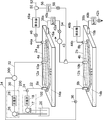
図1を用いてこの実施例のフィールドフローフラクショネーション装置の概略的構成について説明する。
この実施例のフィールドフローフラクショネーション装置は、上段側分離セル2a、下段側分離セル2b、第1キャリア流体供給部100、第1キャリア流体供給部200、流路切替部300、及び制御部400を備えている。上段側分離セル2aと下段側分離セル2bは一対の分離セル対をなしている。フィールドフローフラクショネーション装置は、これらの分離セル対2a,2bを少なくとも含む複数の分離セルからなる分離セル群を備えている。
図1では示されていないが、上段側分離セル2aと下段側分離セル2bはともに試料を分離するための分離チャネルと、その分離チャネルの一端側の位置から該分離チャネル内にキャリア流体を導入するための入口ポート、分離チャネルの入口ポートよりも他端側の位置から該分離チャネル内にキャリア流体を導入するための第2入口ポートを備えている。
第1キャリア流体供給部100は、上段側分離セル2aの入口ポートを介して上段側分離セル2aの分離チャネル内にキャリア流体を供給するものである。第1キャリア流体供給部200は上段側分離セル2aの第2入口ポートを介して上段側分離セル2aの分離チャネル内にキャリア流体を供給するものであるが、第1キャリア流体供給部200と上段側分離セル2aの第2入口ポートとの間に流路切替部300が介在している。
流路切替部300は、第1キャリア流体供給部200の接続先を、上段側分離セル2aの第2入口ポートと、下段側分離セル2bの入口ポート又は第2入口ポートとの間で切り替えるものである。すなわち、上段側分離セル2aの第2入口ポートを介して上段側分離セル2aの分離チャネル内にキャリア流体を供給する第1キャリア流体供給部200を使って、下段側分離セル2bの入口ポート又は第2入口ポートから下段側分離セル2bの分離チャネル内にキャリア流体を供給することができる。
第1キャリア流体供給部100、第1キャリア流体供給部200及び流路切替部300の動作は制御部400によって制御される。
この実施例の具体的な構成の一例を、図1とともに図2を用いて説明する。
分離セル2aは、試料を分離するための分離チャネル4aを備え、その分離チャネル4aに入口ポート6a、出口ポート8a、及び第2入口ポート10aが通じている。入口ポート6aは分離チャネル4aの一端に通じており、出口ポート8aは分離チャネル4aの他端に通じている。第2入口ポート10aは入口ポート6aと出口ポート8aの間の位置に設けられている。図示は省略されているが、分離チャネル4aは、例えば複数の基板が積層されて構成されるブロックの内部に形成されており、各ポート6a、8a及び10aはそのブロックに設けられた孔によって構成されている。
分離チャネル4aは略菱形の形状を有する。分離チャネル4aの一端部と他端部は角部となっており、その平面形状における幅寸法は、一端側から他端側へ行くにしたがって一旦は広くなり、途中から他端へ行くにしたがって幅が狭くなっていき、他端部において収束している。
廃液チャンバ14aが分離膜12aを隔てて分離チャネル4aと隣接するように設けられている。分離膜12aはキャリア流体を通過させつつ試料を通過させない多孔質膜である。廃液チャンバ14aには排出ポート16aが通じており、分離膜12aを通過して分離チャネル4aから廃液チャンバ14aに流入したキャリア流体は、排出ポート16aを介して廃液チャンバ14aから排出される。
分離セル2bも分離セル2aと同様に、分離チャネル4b、入口ポート6b、出口ポート8b、第2入口ポート10b、分離膜12b、廃液チャンバ14b及び排出ポート16bを備えている。
第1キャリア流体供給部4は、入口流路22を介して上段側分離セル2aの入口ポート6aに接続されている。第1キャリア流体供給部4は送液ポンプ17と流量計18を備えている。送液ポンプ17の動作は流量計18の測定値に基づいて制御され、容器20内に貯留されたキャリア流体を所定の流量で送液する。第1キャリア流体供給部4と入口ポート6aとの間の入口流路22上に試料注入部24が設けられている。試料注入部24において入口流路22内に注入された試料は、送液ポンプ17によって送液されるキャリア流体とともに分離チャネル4a内に導入される。入口ポート6aから分離チャネル4a内にキャリア流体が供給されると、分離チャネル4a内では、入口ポート6aから出口ポート8aへ向かうキャリア流体の流れが形成される。
以下において、分離チャネル4a内における入口ポート6aから出口ポート8aへ向かうキャリア流体の流れを「チャネルフロー」、そのチャネルフローに対向する方向のキャリア流体の流れを「フォーカスフロー」、チャネルフローに対して垂直な方向の流れを「クロスフロー」と称する。分離セル4b内においても同様に、入口ポート6bから出口ポート8bへ向かうキャリア流体の流れを「チャネルフロー」、そのチャネルフローに対向する方向のキャリア流体の流れを「フォーカスフロー」、チャネルフローに対して垂直な方向の流れを「クロスフロー」と称する。フォーカスフローは、各分離チャネル4a、4bに第2入口ポート10a、10bからキャリア流体が供給されることによって形成される流れである。クロスフローは、分離膜12a、12bをキャリア流体が通過することによって形成される流れである。
第1キャリア流体供給部200はキャリア流体供給流路30を介して流路切替部300に接続されている。流路切替部300は例えば三方電磁弁によって構成され、キャリア流体供給流路30をフォーカスフロー流路32又は第1リサイクル流路34のいずれか一方の流路に切り替える。フォーカスフロー流路32は上段側分離セル2aの第2入口ポート10aに接続されている。第1リサイクル流路34は下段側分離セル2bの入口ポート6bに接続されている。第1リサイクル流路34上に試料注入部36が設けられている。
第2入口ポート10aを介して分離チャネル4a内にキャリア流体が供給されると、分離チャネル4a内にフォーカスフローが形成される。また、入口ポート6bを介して分離チャネル4b内にキャリア流体が供給されると、分離チャネル4b内にチャネルフローが形成される。
上段側分離セル2aの出口ポート8aに検出流路44aが接続されている。検出流路44上にチェック弁46と検出器48aが設けられている。検出流路44aは検出器48aの下流側の三方ジョイント50において出口流路52と第2リサイクル流路54に分岐している。出口流路52はドレインに通じている。第2リサイクル流路54は下段側分離セル2bの第2入口ポート10bに接続されている。第2リサイクル流路54上には、マスフローコントローラ56及びチェック弁58が設けられている。
上段側分離セル2aの排出ポート16aには排出流路38aが接続されている。排出流路38aは三方電磁弁43を介して下段側分離セル2bの第2入口ポート10bに接続されている。排出流路38a上にはマスフローコントローラ40a及びチェック弁42aが設けられている。三方電磁弁43には排出流路38a、第2入口ポート10bに通じる流路のほかに、ドレインへ通じる流路又は容器20へ通じる流路のいずれかの流路が接続されている。
排出流路38aと第2リサイクル流路54が下段側分離セル2bの第2入口ポート10bに接続されていることで、上段側分離セル2aの出口ポート8aから流出したキャリア流体の少なくとも一部と排出ポート16aから流出したキャリア流体を第2入口ポート10bから分離チャネル4b内に供給することができる。すなわち、上段側分離セル2aからの廃液を利用して分離チャネル4b内にフォーカスフローを形成することができる。
下段側分離セル2bの出口ポート8bに検出流路44bが接続されている。検出流路44b上には検出器48bが設けられている。また、下段側分離セル2bの排出ポート16bには排出流路38bが接続されている。排出流路38b上にはマスフローコントローラ40b及びチェック弁42bが設けられている。排出流路38bはドレインへ通じていてもよいし、容器20にキャリア流体を戻すようになっていてもよい。排出流路38bを介して容器20にキャリア流体が戻されるようになっていれば、キャリア流体の廃液量を低減することができる。
この実施例のフィールドフローフラクショネーション装置の動作について説明する。
上段側分離セル2aにおける試料の分析が下段側分離セル2bでの分析よりも先に開始される。まず、上段側分離セル2aの分離セル4a内に、第1流体供給部4からのキャリア流体が予め設定されたフォーカシング用の第1の流量(例えば、0.05mL/min)で入口ポート6aを介して供給され、試料注入部24により注入された試料も入口ポート6aを介して分離チャネル4a内に導入される。このとき、キャリア流体供給流路30はフォーカスフロー流路32と接続されており、第1キャリア流体供給部200からのキャリア流体が、予め設定されたフォーカシング用の第2の流量(例えば、4.45mL/min)で第2入口ポート10aを介して分離チャネル4a内に供給され、分離チャネル4a内にフォーカスフローが形成される。このフォーカスフローにより、入口ポート6aから導入された試料は、入口ポート6aからのキャリア流体の流れと第2入口ポート10aからのキャリア流体の流れとの境界部分に収集(フォーカシング)される。分離チャネル4a内では、分離膜12aを通過するキャリア流体によるクロスフローも生じており、入口ポート6aからのキャリア流体の流れと第2入口ポート10aからのキャリア流体の流れとの境界部分において試料のリラクゼーションが行われる。
フォーカシング及びリラクゼーションが終了した後、流路切替部300が切り替えられ、キャリア流体供給流路30が第1リサイクル流路34と接続されるとともに、第1キャリア流体供給部200によるキャリア流体の送液流量がフォーカシング用の第1の流量(例えば、0.05mL/min)に変更される。これにより、下段側分離セル2bの入口ポート6bから分離チャネル4a内にキャリア流体が供給され、下段側分離セル2bでの分析が開始される。上段側分離セル2aと同様に、試料が試料注入部36によって第1リサイクル流路34内に注入され、第1リサイクル流路34を流れる第1キャリア流体供給部200からのキャリア流体によって分離チャネル4b内に導入される。
また、フォーカシング及びリラクゼーションが終了した後、第1キャリア流体供給部の流量が予め設定された分離用流量(例えば、4.5mL/min)に変更され、上段側分離セル2aにおける試料の分離が開始される。分離チャネル4a内には、入口ポート6aから出口ポート8aへ流れるキャリア流体によるチャネルフローと、分離膜12aを通過するキャリア流体によるクロスフローが生じる。フォーカシング及びリラクゼーションによって所定位置に収集された試料は、クロスフローによる影響を受けながら出口ポート8a側へ流れ、その影響が少ない粒子から順に検出器48aに導入され、検出される。
分離セル2aにおけるクロスフローの流量はマスフローコントローラ40aによって調節される。クロスフローの流量、すなわち排出流路38aを流れる流量は、予め設定されたクロスフロー流量(例えば、3.5mL/min)に調節される。同時に、第2リサイクル流路54を流れる流量は、予め設定されたリサイクル流量(例えば0.95mL/min)に調節される。すなわち、下段側分離セル2aの分離チャネル4bには、排出流路38aからのキャリア流体と第2リサイクル流路54からのキャリア流体が、合計流量(4.45mL/min)で第2入口ポート10bを介して供給され、分離チャネル4b内にフォーカスフローが形成される。これにより、下段側分離セル2bにおいてフォーカシングが開始される。
下段側分離セル2bにおけるフォーカシング及びリラクゼーションが終了した後は、三方電磁弁43が切り替えられて排出流路38aと第2入口ポート10bとの間の接続が遮断されるとともに、マスフローコントローラ56によって第2リサイクル流路54を流れるキャリア流体の流量が0にされる。これにより、第2入口ポート10bから分離チャネル4b内へのキャリア流体の供給が停止される。そして、第1キャリア流体供給部200からの送液流量が分離用流量(例えば、4.5mL/min)に変更され、上段側分離セル2bにおける試料の分離が開始される。分離チャネル4b内には、入口ポート6bから出口ポート8bへ流れるキャリア流体によるチャネルフローと、分離膜12bを通過するキャリア流体によるクロスフローが生じる。フォーカシング及びリラクゼーションによって所定位置に収集された試料は、クロスフローによる影響を受けながら出口ポート8b側へ流れ、その影響が少ない粒子から順に検出器48bに導入され、検出される。
以上において説明した実施例では、上段側分離セル2aの出口ポート8aから排出されるキャリア流体と排出ポート16aから排出されるキャリア流体を、下段側分離セル2bの分離チャネル4b内にフォーカスフローを形成するためのキャリア流体として利用するように構成されているが、本発明はこれに限定されるものではなく、上段側分離セル2aの廃液を下段側分離セル2bに導入しないように構成されていてもよい。その場合、上段側分離セル2aの廃液のうち試料を含まない部分を容器20に戻すようになっていることがキャリア流体の廃液量の低減の観点から好ましいが、必ずしもそのように構成されている必要はない。
上記実施例では、上段側分離セル2aでのフォーカシング及びリラクゼーションが終了した後で、第1キャリア流体供給部200からのキャリア流体を下段側分離セル2bの入口ポート6bから分離セル4b内に供給するように構成されているが、本発明はこれに限定されるものではない。要は、上段側分離セル2aでのフォーカシング及びリラクゼーションが終了した後、上段側分離セル2aにとっては不要となった第1キャリア流体供給部200を下段側分離セル2bのために使用するように構成されていればよい。
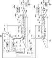
図3は、上段側分離セル2aでのフォーカシング及びリラクゼーションが終了した後、第1キャリア流体供給部200からのキャリア流体を下段側分離セル2bの第2入口ポート10bから分離チャネル4b内に供給するように構成した実施例を示している。この実施例では、リサイクル流路34が下段側分離セル2bの第2入口ポート10bに接続されている。下段側分離セル2bの入口ポート6bには、第2入口流路60が接続されている。第2入口流路60上には、容器20内に貯留されたキャリア流体を送液する送液ポンプ62、流量計64及び試料注入部66が設けられている。
図3の実施例において、排出流路38a及び38bは容器20に通じていて排出ポート16a及び16bから排出されたキャリア流体を容器20に戻すように構成されていることが好ましいが、必ずしもそのように構成されていなくてもよい。
2a,2b 分離セル
4a,4b 分離チャネル
6a,6b 入口ポート
8a,8b 出口ポート
10a,10b 第2入口ポート
12a,12b 分離膜
14a,14b 廃液チャンバ
16a,16b 排出ポート
17,26,62 送液ポンプ
18,28,64 流量計
20 キャリア流体用の容器
22 入口流路
24,36,66 試料注入部
30 キャリア流体供給流路
32 フォーカスフロー流路
34 第1リサイクル流路
38a,38b 排出流路
40a,40b,56 マスフローコントローラ
42a,42b,46,58 チェック弁
43,300 三方電磁弁
44a,44b 検出流路
48a,48b 検出器
50 三方ジョイント
52 出口流路
54 第2リサイクル流路
100 第1キャリア流体供給部
200 第2キャリア流体供給部
400 制御部
4a,4b 分離チャネル
6a,6b 入口ポート
8a,8b 出口ポート
10a,10b 第2入口ポート
12a,12b 分離膜
14a,14b 廃液チャンバ
16a,16b 排出ポート
17,26,62 送液ポンプ
18,28,64 流量計
20 キャリア流体用の容器
22 入口流路
24,36,66 試料注入部
30 キャリア流体供給流路
32 フォーカスフロー流路
34 第1リサイクル流路
38a,38b 排出流路
40a,40b,56 マスフローコントローラ
42a,42b,46,58 チェック弁
43,300 三方電磁弁
44a,44b 検出流路
48a,48b 検出器
50 三方ジョイント
52 出口流路
54 第2リサイクル流路
100 第1キャリア流体供給部
200 第2キャリア流体供給部
400 制御部
Claims (4)
- キャリア流体が流れサンプルを分離するための分離チャネル、前記分離チャネルの一端に通じる入口ポート、前記入口ポートよりも前記分離チャネルの他端側に通じる第2入口ポート、及びキャリア流体を通過させつつサンプルを通過させない性質をもつ分離膜を隔てて前記分離チャネルと隣接する廃液チャンバを有する複数の分離セルからなり、上段側分離セルと下段側分離セルで構成される分離セル対を少なくとも一対有する分離セル群と、
前記分離セル群の上段側分離セルの前記入口ポートに接続されて該上段側分離セルの前記分離チャネルにキャリア流体を供給する第1キャリア流体供給部と、
前記第1キャリア流体供給部とは別途設けられ、前記第1キャリア流体供給部から独立してキャリア流体を送液する第2キャリア流体供給部と、
前記第2キャリア流体供給部を、前記上段側分離セルの前記第2入口ポート、又は前記下段側分離セルの前記入口ポート若しくは前記下段側分離セルの第2入口ポートのいずれか一方のポートに切り替えて接続する流路切替部と、
前記上段側分離セル内に前記入口ポートからのキャリア流体の流れと対向するキャリア流体の流れを生じさせるフォーカシングの際に、前記第2キャリア流体供給部を前記上段側分離セルの前記第2入口ポートに接続し、前記上段側分離セルでのフォーカシングが終了した後で、前記第2キャリア流体供給部を前記下段側分離セルの前記入口ポート又は前記第2入口ポートに接続するように、前記流路切替部の動作制御を少なくとも行なう制御部と、を備えたフィールドフローフラクショネーション装置。 - 前記流路切替部は、前記第2キャリア流体供給部を、前記上段側分離セルの前記第2入口ポート又は前記下段側分離セルの前記入口ポートのいずれか一方のポートに切り替えて接続するものであり、
前記制御部は、前記上段側分離セルでのフォーカシングが終了した後で、前記第2キャリア流体供給部を前記下段側分離セルの前記入口ポートに接続するように前記流路切替部の動作制御を行なうものである請求項1に記載のフィールドフローフラクショネーション装置。 - 前記分離セルは、前記廃液チャンバのキャリア流体を排出するための排出ポートをさらに備え、
前記下段側分離セルのフォーカシングの際に、前記上段側分離セルの前記排出ポートからのキャリア流体が前記下段側分離セルの前記第2入口から該下段側分離セルの前記分離チャネルに供給されるように構成されている請求項2に記載のフィールドフローフラクショネーション装置。 - 前記流路切替部は、前記第2キャリア流体供給部を、前記上段側分離セルの前記第2入口ポート又は前記下段側分離セルの前記第2入口ポートのいずれか一方のポートに切り替えて接続するものであり、
前記制御部は、前記上段側分離セルでのフォーカシングが終了した後で、前記第2キャリア流体供給部を前記下段側分離セルの前記第2入口ポートに接続するように前記流路切替部の動作制御を行なうものである請求項1に記載のフィールドフローフラクショネーション装置。
Priority Applications (3)
| Application Number | Priority Date | Filing Date | Title |
|---|---|---|---|
| CN201780030451.1A CN109153022B (zh) | 2016-09-20 | 2017-09-14 | 场流分离装置 |
| US16/334,469 US11619615B2 (en) | 2016-09-20 | 2017-09-14 | Field flow fractionation device |
| JP2018541013A JP6614360B2 (ja) | 2016-09-20 | 2017-09-14 | フィールドフローフラクショネーション装置 |
Applications Claiming Priority (2)
| Application Number | Priority Date | Filing Date | Title |
|---|---|---|---|
| JP2016182630 | 2016-09-20 | ||
| JP2016-182630 | 2016-09-20 |
Publications (1)
| Publication Number | Publication Date |
|---|---|
| WO2018056166A1 true WO2018056166A1 (ja) | 2018-03-29 |
Family
ID=61690445
Family Applications (1)
| Application Number | Title | Priority Date | Filing Date |
|---|---|---|---|
| PCT/JP2017/033264 Ceased WO2018056166A1 (ja) | 2016-09-20 | 2017-09-14 | フィールドフローフラクショネーション装置 |
Country Status (4)
| Country | Link |
|---|---|
| US (1) | US11619615B2 (ja) |
| JP (1) | JP6614360B2 (ja) |
| CN (1) | CN109153022B (ja) |
| WO (1) | WO2018056166A1 (ja) |
Cited By (5)
| Publication number | Priority date | Publication date | Assignee | Title |
|---|---|---|---|---|
| EP3553514A1 (en) * | 2018-04-11 | 2019-10-16 | Shimadzu Corporation | Field flow fractionation apparatus |
| WO2019198178A1 (ja) * | 2018-04-11 | 2019-10-17 | 株式会社島津製作所 | フィールドフローフラクショネーション装置 |
| JP2020124662A (ja) * | 2019-02-04 | 2020-08-20 | 株式会社島津製作所 | フィールドフローフラクショネーション装置及び洗浄方法 |
| JP2020175378A (ja) * | 2019-04-16 | 2020-10-29 | 東ソー株式会社 | 分散溶媒置換装置 |
| JP2021016805A (ja) * | 2019-07-17 | 2021-02-15 | 株式会社島津製作所 | 非対称流流動場分画装置 |
Families Citing this family (3)
| Publication number | Priority date | Publication date | Assignee | Title |
|---|---|---|---|---|
| CN110261520B (zh) * | 2019-08-06 | 2023-08-11 | 河北大学 | 非对称场流分离装置及分离检测样品的方法 |
| US12076661B2 (en) | 2020-10-14 | 2024-09-03 | Wyatt Technology LLC | Managing solvent associated with a field flow fractionator |
| CN116870592A (zh) * | 2023-07-18 | 2023-10-13 | 河北瑞熠天淀粉制造有限公司 | 一种非对称场流分离装置 |
Citations (3)
| Publication number | Priority date | Publication date | Assignee | Title |
|---|---|---|---|---|
| WO2000016907A1 (en) * | 1998-09-18 | 2000-03-30 | The University Of Utah Research Foundation | Micromachined electrical field-flow fractionation system |
| US6192764B1 (en) * | 1998-02-27 | 2001-02-27 | Fffractionation, Llc | Sample focusing device and method |
| US6365050B1 (en) * | 2000-08-22 | 2002-04-02 | Amgen Inc. | Method for stopless and splitless flow field-flow fractionation |
Family Cites Families (7)
| Publication number | Priority date | Publication date | Assignee | Title |
|---|---|---|---|---|
| US6641708B1 (en) * | 1996-01-31 | 2003-11-04 | Board Of Regents, The University Of Texas System | Method and apparatus for fractionation using conventional dielectrophoresis and field flow fractionation |
| US6180906B1 (en) * | 1997-12-12 | 2001-01-30 | Wyatt Technology Corporation | Electrode design for electrical field flow fractionation |
| JP4770603B2 (ja) | 2006-06-26 | 2011-09-14 | 株式会社島津製作所 | フィールドフローフラクショネーション装置 |
| US8360244B2 (en) * | 2008-06-09 | 2013-01-29 | Wyatt Technology Corporation | Method and apparatus for optimizing the separation of small particles using the asymmetric flow field flow fractionation method |
| JP2015052592A (ja) * | 2013-08-07 | 2015-03-19 | アークレイ株式会社 | 液体クロマトグラフィ装置、液体クロマトグラフィ分析方法、及び液体クロマトグラフィ分析プログラム |
| JP6372147B2 (ja) * | 2014-04-23 | 2018-08-15 | 株式会社島津製作所 | タンパク質に対する親和性評価のための分析方法及びその装置 |
| CN205317732U (zh) * | 2015-12-31 | 2016-06-15 | 杭州谱育科技发展有限公司 | 非甲烷总烃及苯系物在线检测装置 |
-
2017
- 2017-09-14 CN CN201780030451.1A patent/CN109153022B/zh active Active
- 2017-09-14 JP JP2018541013A patent/JP6614360B2/ja active Active
- 2017-09-14 US US16/334,469 patent/US11619615B2/en active Active
- 2017-09-14 WO PCT/JP2017/033264 patent/WO2018056166A1/ja not_active Ceased
Patent Citations (3)
| Publication number | Priority date | Publication date | Assignee | Title |
|---|---|---|---|---|
| US6192764B1 (en) * | 1998-02-27 | 2001-02-27 | Fffractionation, Llc | Sample focusing device and method |
| WO2000016907A1 (en) * | 1998-09-18 | 2000-03-30 | The University Of Utah Research Foundation | Micromachined electrical field-flow fractionation system |
| US6365050B1 (en) * | 2000-08-22 | 2002-04-02 | Amgen Inc. | Method for stopless and splitless flow field-flow fractionation |
Cited By (15)
| Publication number | Priority date | Publication date | Assignee | Title |
|---|---|---|---|---|
| JP7036197B2 (ja) | 2018-04-11 | 2022-03-15 | 株式会社島津製作所 | フィールドフローフラクショネーション装置 |
| WO2019198178A1 (ja) * | 2018-04-11 | 2019-10-17 | 株式会社島津製作所 | フィールドフローフラクショネーション装置 |
| JP2019181373A (ja) * | 2018-04-11 | 2019-10-24 | 株式会社島津製作所 | フィールドフローフラクショネーション装置 |
| EP3553514A1 (en) * | 2018-04-11 | 2019-10-16 | Shimadzu Corporation | Field flow fractionation apparatus |
| US11819859B2 (en) | 2018-04-11 | 2023-11-21 | Shimadzu Corporation | Field flow fractionation device |
| CN111971127A (zh) * | 2018-04-11 | 2020-11-20 | 株式会社岛津制作所 | 场流分离装置 |
| CN111971127B (zh) * | 2018-04-11 | 2022-06-24 | 株式会社岛津制作所 | 场流分离装置 |
| JPWO2019198178A1 (ja) * | 2018-04-11 | 2021-02-25 | 株式会社島津製作所 | フィールドフローフラクショネーション装置 |
| EP3778031A4 (en) * | 2018-04-11 | 2021-12-22 | Shimadzu Corporation | FIELD FLOW FRACTION DEVICE |
| JP2020124662A (ja) * | 2019-02-04 | 2020-08-20 | 株式会社島津製作所 | フィールドフローフラクショネーション装置及び洗浄方法 |
| JP7172674B2 (ja) | 2019-02-04 | 2022-11-16 | 株式会社島津製作所 | フィールドフローフラクショネーション装置及び洗浄方法 |
| JP2020175378A (ja) * | 2019-04-16 | 2020-10-29 | 東ソー株式会社 | 分散溶媒置換装置 |
| JP7585606B2 (ja) | 2019-04-16 | 2024-11-19 | 東ソー株式会社 | 分散溶媒置換装置 |
| JP2021016805A (ja) * | 2019-07-17 | 2021-02-15 | 株式会社島津製作所 | 非対称流流動場分画装置 |
| JP7215366B2 (ja) | 2019-07-17 | 2023-01-31 | 株式会社島津製作所 | 非対称流流動場分画装置 |
Also Published As
| Publication number | Publication date |
|---|---|
| CN109153022B (zh) | 2020-07-31 |
| JP6614360B2 (ja) | 2019-12-04 |
| US11619615B2 (en) | 2023-04-04 |
| CN109153022A (zh) | 2019-01-04 |
| US20210372972A1 (en) | 2021-12-02 |
| JPWO2018056166A1 (ja) | 2019-03-14 |
Similar Documents
| Publication | Publication Date | Title |
|---|---|---|
| JP6614360B2 (ja) | フィールドフローフラクショネーション装置 | |
| US12290762B2 (en) | System for preparing solutions for chromatography | |
| US9941104B2 (en) | Systems and methods for delivering liquid to an ion source | |
| JPH0554063B2 (ja) | ||
| US11592425B2 (en) | Cleaning method of field-flow-fractionation apparatus | |
| CN110361303B (zh) | 场流分级装置 | |
| JP7036197B2 (ja) | フィールドフローフラクショネーション装置 | |
| CN107110833A (zh) | 气相色谱仪和用于气相色谱仪的多向阀单元 | |
| CN113631919B (zh) | 离子色谱仪及离子成分分析方法 | |
| JP2014062827A (ja) | 脱気送液装置及び分析装置 | |
| CN112384302A (zh) | 场流分离装置 | |
| KR102410793B1 (ko) | 액체 샘플링 장치 및 액체 샘플링 방법 | |
| US12005446B2 (en) | High throughput compact microfluidic cell counter | |
| JP2004045410A (ja) | 試料分離装置及び化学分析装置 | |
| CN113646629B (zh) | 离子色谱仪 | |
| JP7324743B2 (ja) | 化学分析法の試料調製用透析セル | |
| JPS63184035A (ja) | 粒子単離分注器 | |
| JPH11264814A (ja) | 試料分離装置及び化学分析装置 |
Legal Events
| Date | Code | Title | Description |
|---|---|---|---|
| ENP | Entry into the national phase |
Ref document number: 2018541013 Country of ref document: JP Kind code of ref document: A |
|
| 121 | Ep: the epo has been informed by wipo that ep was designated in this application |
Ref document number: 17852943 Country of ref document: EP Kind code of ref document: A1 |
|
| NENP | Non-entry into the national phase |
Ref country code: DE |
|
| 122 | Ep: pct application non-entry in european phase |
Ref document number: 17852943 Country of ref document: EP Kind code of ref document: A1 |