WO2018055940A1 - メッシュ式ネブライザおよび薬液パック - Google Patents
メッシュ式ネブライザおよび薬液パック Download PDFInfo
- Publication number
- WO2018055940A1 WO2018055940A1 PCT/JP2017/028910 JP2017028910W WO2018055940A1 WO 2018055940 A1 WO2018055940 A1 WO 2018055940A1 JP 2017028910 W JP2017028910 W JP 2017028910W WO 2018055940 A1 WO2018055940 A1 WO 2018055940A1
- Authority
- WO
- WIPO (PCT)
- Prior art keywords
- mesh
- peripheral wall
- main body
- chemical
- pack
- Prior art date
- Legal status (The legal status is an assumption and is not a legal conclusion. Google has not performed a legal analysis and makes no representation as to the accuracy of the status listed.)
- Ceased
Links
Images


Classifications
-
- A—HUMAN NECESSITIES
- A61—MEDICAL OR VETERINARY SCIENCE; HYGIENE
- A61M—DEVICES FOR INTRODUCING MEDIA INTO, OR ONTO, THE BODY; DEVICES FOR TRANSDUCING BODY MEDIA OR FOR TAKING MEDIA FROM THE BODY; DEVICES FOR PRODUCING OR ENDING SLEEP OR STUPOR
- A61M11/00—Sprayers or atomisers specially adapted for therapeutic purposes
- A61M11/005—Sprayers or atomisers specially adapted for therapeutic purposes using ultrasonics
-
- A—HUMAN NECESSITIES
- A61—MEDICAL OR VETERINARY SCIENCE; HYGIENE
- A61M—DEVICES FOR INTRODUCING MEDIA INTO, OR ONTO, THE BODY; DEVICES FOR TRANSDUCING BODY MEDIA OR FOR TAKING MEDIA FROM THE BODY; DEVICES FOR PRODUCING OR ENDING SLEEP OR STUPOR
- A61M15/00—Inhalators
- A61M15/0001—Details of inhalators; Constructional features thereof
- A61M15/0021—Mouthpieces therefor
- A61M15/0023—Mouthpieces therefor retractable
-
- A—HUMAN NECESSITIES
- A61—MEDICAL OR VETERINARY SCIENCE; HYGIENE
- A61M—DEVICES FOR INTRODUCING MEDIA INTO, OR ONTO, THE BODY; DEVICES FOR TRANSDUCING BODY MEDIA OR FOR TAKING MEDIA FROM THE BODY; DEVICES FOR PRODUCING OR ENDING SLEEP OR STUPOR
- A61M15/00—Inhalators
- A61M15/0028—Inhalators using prepacked dosages, one for each application, e.g. capsules to be perforated or broken-up
-
- A—HUMAN NECESSITIES
- A61—MEDICAL OR VETERINARY SCIENCE; HYGIENE
- A61M—DEVICES FOR INTRODUCING MEDIA INTO, OR ONTO, THE BODY; DEVICES FOR TRANSDUCING BODY MEDIA OR FOR TAKING MEDIA FROM THE BODY; DEVICES FOR PRODUCING OR ENDING SLEEP OR STUPOR
- A61M15/00—Inhalators
- A61M15/0085—Inhalators using ultrasonics
-
- B—PERFORMING OPERATIONS; TRANSPORTING
- B05—SPRAYING OR ATOMISING IN GENERAL; APPLYING FLUENT MATERIALS TO SURFACES, IN GENERAL
- B05B—SPRAYING APPARATUS; ATOMISING APPARATUS; NOZZLES
- B05B17/00—Apparatus for spraying or atomising liquids or other fluent materials, not covered by the preceding groups
- B05B17/04—Apparatus for spraying or atomising liquids or other fluent materials, not covered by the preceding groups operating with special methods
- B05B17/06—Apparatus for spraying or atomising liquids or other fluent materials, not covered by the preceding groups operating with special methods using ultrasonic or other kinds of vibrations
- B05B17/0607—Apparatus for spraying or atomising liquids or other fluent materials, not covered by the preceding groups operating with special methods using ultrasonic or other kinds of vibrations generated by electrical means, e.g. piezoelectric transducers
- B05B17/0623—Apparatus for spraying or atomising liquids or other fluent materials, not covered by the preceding groups operating with special methods using ultrasonic or other kinds of vibrations generated by electrical means, e.g. piezoelectric transducers coupled with a vibrating horn
-
- A—HUMAN NECESSITIES
- A61—MEDICAL OR VETERINARY SCIENCE; HYGIENE
- A61M—DEVICES FOR INTRODUCING MEDIA INTO, OR ONTO, THE BODY; DEVICES FOR TRANSDUCING BODY MEDIA OR FOR TAKING MEDIA FROM THE BODY; DEVICES FOR PRODUCING OR ENDING SLEEP OR STUPOR
- A61M2202/00—Special media to be introduced, removed or treated
- A61M2202/04—Liquids
- A61M2202/0468—Liquids non-physiological
-
- A—HUMAN NECESSITIES
- A61—MEDICAL OR VETERINARY SCIENCE; HYGIENE
- A61M—DEVICES FOR INTRODUCING MEDIA INTO, OR ONTO, THE BODY; DEVICES FOR TRANSDUCING BODY MEDIA OR FOR TAKING MEDIA FROM THE BODY; DEVICES FOR PRODUCING OR ENDING SLEEP OR STUPOR
- A61M2205/00—General characteristics of the apparatus
- A61M2205/02—General characteristics of the apparatus characterised by a particular materials
- A61M2205/0216—Materials providing elastic properties, e.g. for facilitating deformation and avoid breaking
-
- A—HUMAN NECESSITIES
- A61—MEDICAL OR VETERINARY SCIENCE; HYGIENE
- A61M—DEVICES FOR INTRODUCING MEDIA INTO, OR ONTO, THE BODY; DEVICES FOR TRANSDUCING BODY MEDIA OR FOR TAKING MEDIA FROM THE BODY; DEVICES FOR PRODUCING OR ENDING SLEEP OR STUPOR
- A61M2205/00—General characteristics of the apparatus
- A61M2205/12—General characteristics of the apparatus with interchangeable cassettes forming partially or totally the fluid circuit
- A61M2205/123—General characteristics of the apparatus with interchangeable cassettes forming partially or totally the fluid circuit with incorporated reservoirs
-
- A—HUMAN NECESSITIES
- A61—MEDICAL OR VETERINARY SCIENCE; HYGIENE
- A61M—DEVICES FOR INTRODUCING MEDIA INTO, OR ONTO, THE BODY; DEVICES FOR TRANSDUCING BODY MEDIA OR FOR TAKING MEDIA FROM THE BODY; DEVICES FOR PRODUCING OR ENDING SLEEP OR STUPOR
- A61M2205/00—General characteristics of the apparatus
- A61M2205/82—Internal energy supply devices
- A61M2205/8206—Internal energy supply devices battery-operated
-
- A—HUMAN NECESSITIES
- A61—MEDICAL OR VETERINARY SCIENCE; HYGIENE
- A61M—DEVICES FOR INTRODUCING MEDIA INTO, OR ONTO, THE BODY; DEVICES FOR TRANSDUCING BODY MEDIA OR FOR TAKING MEDIA FROM THE BODY; DEVICES FOR PRODUCING OR ENDING SLEEP OR STUPOR
- A61M2210/00—Anatomical parts of the body
- A61M2210/06—Head
- A61M2210/0625—Mouth
Definitions
- the present invention relates to a mesh type nebulizer, and more particularly to a mesh type nebulizer that atomizes a liquid supplied between a vibrating surface and a mesh portion and ejects the liquid through the mesh portion.
- the present invention also relates to a chemical pack suitable for constituting such a mesh nebulizer.
- the main body is provided with a horn vibrator, and can be attached to and detached from the main body and can be opened and closed (rotated). It is known to have a mesh cap that can be moved).
- the vibration surface of the horn vibrator faces the mesh portion of the mesh cap.
- a chemical solution is supplied between the vibration surface and the mesh portion, and a driving voltage is applied to the horn vibrator to vibrate the vibration surface.
- medical solution is atomized through the said mesh part, and it ejects.
- the mesh type nebulizer it is necessary to remove the mesh cap from the main body each time after use, and to wash, disinfect, and dry the mesh cap including the mesh portion. For this reason, there is a problem that care is troublesome for the user. Furthermore, since the mesh cap is a precision part, there is a problem that it is easily damaged by cleaning and is difficult to clean. Further, if the mesh part is not properly cleaned, there is a problem that it is unsanitary and the spray efficiency is lowered.
- an object of the present invention is to provide a mesh type nebulizer that is hygienic and can be easily maintained by a user without lowering the spray efficiency.
- an object of the present invention is to provide a chemical pack suitable for constructing such a mesh nebulizer.
- the mesh nebulizer of the present invention is It is a mesh type nebulizer that atomizes and ejects chemicals through the mesh part, A main body provided with a vibration part having a vibration surface; A chemical pack that is detachably attached to the main body, The above chemical pack is A lid member on which the mesh portion is formed; It has a recess that opens toward the mesh portion and is covered with the lid member, and a chemical solution storage member that stores a chemical solution to be supplied toward the vibration surface in the recess.
- the bottom surface of the concave portion of the chemical solution storage member at least a portion to be opposed to the vibration surface is formed of a material having extensibility, When the chemical pack is attached to the main body, the stretchable material on the bottom surface extends to allow the vibration surface to approach the mesh portion of the lid member.
- the planar shape of the concave portion widely includes an annular shape such as a circle and a rounded square (a square with rounded corners).
- a chemical pack is detachably attached to the main body in advance for use.
- This chemical solution pack includes a lid member in which a mesh portion is formed and a chemical solution storage member that has a concave portion that opens toward the mesh portion and is covered by the lid member, and in which the chemical solution is accommodated. Yes.
- at least a portion of the bottom surface of the concave portion of the chemical solution storage member that should face the vibration surface is formed of a stretchable material.
- the chemical pack is removed from the main body and discarded.
- the mesh type nebulizer of the present invention is equipped with a new chemical pack every time it is used, it is not necessary to clean the mesh portion. Therefore, it is hygienic and easy to clean for the user without reducing the spray efficiency. Furthermore, since a new mesh part is used every time it is used, it is hygienic and the spray efficiency is not reduced.
- the main body An inner peripheral wall surrounding the vibration surface; An outer peripheral wall that is concentric with the inner peripheral wall and is rotatably arranged around the inner peripheral wall; A cylindrical member that is interposed between the inner peripheral wall and the outer peripheral wall, and a holder member that receives and holds the drug pack through an opening formed in a part of the peripheral wall; An elevating mechanism is provided for raising or lowering the holder member relative to the inner peripheral wall as the outer peripheral wall of the main body is rotated around the inner peripheral wall.
- the main body has a cylindrical holder member in which a chemical pack is to be held.
- the holder member is provided with an opening in a part of the peripheral wall in which the chemical pack is to be taken in and out, and the peripheral wall is arranged inside the outer peripheral wall.
- an elevating mechanism is provided for raising or lowering the holder member with respect to the inner peripheral wall as the outer peripheral wall is rotated around the inner peripheral wall.
- the elevating mechanism lowers the holder member, and the opening portion of the peripheral wall can be arranged inside the outer peripheral wall.
- the outer peripheral wall is rotated around the inner peripheral wall, and when the holder member is lowered with respect to the inner peripheral wall by the lifting mechanism, The bottom surface approaches and comes into contact with the vibration surface. And the raw material which has the said extensibility of the said bottom face of the said chemical
- the chemical pack is removed from the main body, the outer peripheral wall is rotated around the inner peripheral wall, and when the holder member is raised with respect to the inner peripheral wall by the elevating mechanism, the chemical pack is vibrated. Separate from the surface. In this way, the user can remove the chemical pack from the main body.
- the lifting mechanism includes a first screw element provided on the outer peripheral surface of the holder member, and a second screw element formed on the inner surface of the outer peripheral wall of the main body so as to be able to engage with the first screw element. It is provided with.
- the first screw element is formed on the outer peripheral surface of the holder member, and the second screw element that engages with the first screw element is formed on the inner surface of the outer peripheral wall. For this reason, it becomes possible to raise or lower the holder member by rotating the outer peripheral wall. Furthermore, since the screw elements are configured only by forming grooves on the respective surfaces, the screw elements can be easily configured and are not easily damaged.
- the chemical pack of the present invention is a chemical pack to be attached to the mesh nebulizer, A lid member on which the mesh portion is formed; It has a recess that opens toward the mesh portion and is covered with the lid member, and a chemical solution storage member that stores a chemical solution to be supplied toward the vibration surface in the recess.
- a portion to be opposed to the vibration surface is formed of a material having extensibility.
- the chemical pack of the present invention is suitable for constituting the mesh nebulizer.
- the lid member includes a flange portion formed by extending outward from the upper edge of the chemical solution storage member, When the chemical pack is attached to the main body, the flange portion of the lid member is supported by the upper edge of the inner peripheral wall surrounding the vibration surface of the main body.
- the lid member includes a flange portion formed to extend outward from the upper edge of the chemical solution storage member. Therefore, when the chemical pack is attached to the main body, the flange portion of the lid member can be supported by the upper edge of the inner peripheral wall of the main body.
- the lid member has a flat shape
- the recess includes a deep first region where the chemical solution is stored and a second region shallower than the first region,
- the bottom surface of the concave portion of the chemical solution storage member to be opposed to the vibration surface is disposed in the second region.
- the concave portion has a shallow region and a deep region, and the bottom surface of the concave portion of the chemical solution storage member to be opposed to the vibration surface is disposed in the shallow region.
- the mesh nebulizer of the present invention is easy to care for the user. Furthermore, since a new mesh part is used every time it is used, it is hygienic and the spray efficiency is not reduced.
- the chemical pack of the present invention is suitable for constituting the mesh nebulizer.
- the place which looked at the mesh type nebulizer of one Embodiment of this invention from diagonally is shown. It is a perspective view of the chemical
- the block configuration of the control system mounted in the main body of the mesh type nebulizer of FIG. 1 is shown.
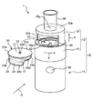
- FIG. 1 shows a mesh type nebulizer according to an embodiment of the present invention (the whole is denoted by reference numeral 1) as viewed obliquely.
- the mesh nebulizer 1 includes a main body lower part 11 having a substantially cylindrical outer shape, and a main body upper part 12 fitted to the main body lower part 11 and having a substantially cylindrical outer shape.
- the main body upper portion 12 is fitted to the main body lower portion 11 and can be rotated in the circumferential direction (arrow A), and a cylinder that rises or falls in the vertical direction (arrow B) according to the rotation of the outer peripheral wall 31.
- Shaped holder member 30 The holder member 30 holds a chemical pack 20 to be described later.
- the main body lower portion 11 and the main body upper portion 12 constitute a main body 10.
- a power switch 50 for turning on / off the power supply of the nebulizer 1 is provided on the front surface of the lower part 11 of the main body.
- a control system which will be described later is mainly mounted in the lower part 11 of the main body.
- an opening 30o is provided on the upper surface 30a of the holder member 30, and a mouthpiece 80, for example, is detachably attached to the opening 30o.
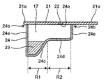
- FIG. 2A is a perspective view of the chemical pack 20 attached to the mesh nebulizer 1 of FIG. 1, and FIG. 2B is a longitudinal sectional view taken along the line DD of FIG. 2A.
- the chemical solution pack 20 includes a chemical solution storage member 24 having a recess 17 and a lid member 21 that covers the chemical solution storage member 24 and has a substantially flat shape.
- the chemical solution storage member 24 of the chemical solution pack 20 includes a deep first region R1 in which the chemical solution 23 is stored and a second region R2 that is shallower than the first region R1.
- the bottom surface 24c of the concave portion 17 of the chemical solution storage member 24 to be opposed to a vibration surface 43 described later is disposed in the second region.
- a portion 24d of the bottom surface 24c of the concave portion 17 of the chemical solution storage member 24 that should face a vibration surface 43 described later is formed of a material having extensibility.
- a mesh portion 24 a is formed in the approximate center of the lid member 21 of the chemical pack 20.
- the lid member 21 includes a flange portion 21 a formed by extending outward from the upper edge 24 b of the side wall 24 e of the chemical solution storage member 24.
- FIG. 3 is a view showing a part of a longitudinal section when the mesh nebulizer 1 of FIG. 1 is viewed from the right side (the direction indicated by the arrow C in FIG. 1).
- FIG. 3 shows the mesh nebulizer 1 in a state where the chemical pack 20 is not attached to the main body 10 of the mesh nebulizer 1.
- the lower part 11 of the main body includes an inner peripheral wall 16 c surrounding the vibration surface 43.
- the vibration surface 43 and the inner peripheral wall 16c are integrally formed.
- the main body upper portion 12 includes an outer peripheral wall 31 that is concentric with the inner peripheral wall 16c of the main body lower portion 11 and is rotatably arranged around the inner peripheral wall 16c.
- a convex portion 11a is formed in a ring shape along the outer periphery above the lower portion 11 of the main body.
- the outer peripheral wall 31 of the main body upper portion 12 is formed with a concave portion 31 a that is fitted to the convex portion 11 a of the lower main body 11. With this configuration, the outer peripheral wall 31 of the main body upper portion 12 can be rotated in the circumferential direction.
- a concave portion 16 opened upward is provided on the upper surface of the lower part 11 of the main body so that the chemical pack 20 can be fitted.
- the concave portion 16 includes a third region R3 fitted into the first region R1 of the chemical solution pack 20 of FIGS. 2A and 2B and a fourth region fitted into the second region R2 of the chemical solution pack 20.
- the third region R3 is deeper than the fourth region R4.
- the chemical pack 20 can be fitted into the recess 16.
- the flange portion 21 a of the lid member 21 of the chemical pack 20 is supported by the upper edge 16 a of the inner peripheral wall 16 c of the main body 10. Is done.
- a vibrating portion 40 is provided on the bottom surface 16b of the fourth region R4 of the recess 16.
- the vibration unit 40 includes an ultrasonic transducer 41 provided on the bottom surface 16b of the fourth region R4 of the recess 16, and a vibration surface 43 horizontally disposed at a position corresponding to the bottom surface 16b of the fourth region R4 of the recess 16.
- a horn 42 that is disposed between the ultrasonic transducer 41 and the vibration surface 43 and amplifies the vibration of the ultrasonic transducer 41 and transmits the vibration to the vibration surface 43.
- a driving voltage for the ultrasonic transducer 41 is supplied from the lower body 11 through a contact electrode provided between the upper body 12 and the lower body 11.
- the holder member 30 has an opening 30b in which a chemical pack 20 is to be taken in and out in a part of the peripheral wall.
- the peripheral wall of the holder member 30 is interposed between the inner peripheral wall 16 c and the outer peripheral wall 31. That is, the holder member 30 has a cylindrical peripheral wall inserted between the inner peripheral wall 16c and the outer peripheral wall 31, and receives and holds the drug solution pack 20 through an opening 30b formed in a part of the peripheral wall. .
- the mesh nebulizer 1 includes an elevating mechanism 100 that raises or lowers the holder member 30 relative to the main body 10 as the outer peripheral wall 31 of the main body 10 is rotated around the inner peripheral wall 16c.
- the lifting mechanism 100 includes a first screw element 33 provided on the outer peripheral surface of the holder member 30, and a second screw formed on the inner surface of the outer peripheral wall 31 of the main body 10 so as to be able to engage with the first screw element 33. And a screw element 34.
- the holder member 30 can be lowered. Therefore, the opening 30 b is arranged inside the outer peripheral wall 31, and the opening 30 b is closed by the outer peripheral wall 31.
- FIG. 4 shows a block configuration of a control system mounted on the main body 10 of the mesh nebulizer 1.
- the mesh nebulizer 1 includes an operation unit 61, a notification unit 62, a control unit 63, an oscillation frequency generation unit 64, an atomization unit 65, and a power supply unit 66.
- the operation unit 61 includes the power switch 50 shown in FIG.
- the notification unit 62 may include a buzzer (not shown), for example.
- the oscillation frequency generation unit 64 applies an alternating drive voltage to the atomization unit 65 based on a control signal from the control unit 63. This drive voltage is output over a certain output time after the power switch 50 is pressed, for example. The output time can be measured by a timer (not shown).
- the atomizing unit 65 includes the vibrating unit 40 and the mesh unit 24a of the chemical pack 20 shown in FIG.
- the AC drive voltage from the oscillation frequency generation unit 64 is applied to the ultrasonic transducer 41 of the vibration unit 40 that forms the atomization unit 65.
- the vibration of the ultrasonic transducer 41 is amplified by the horn 42 and transmitted to the vibration surface 43.
- the control unit 63 includes a CPU (Central Processing Unit) and sends a signal to the atomization unit 65 via the oscillation frequency generation unit 64 to control the atomization amount, the continuous operation time, and the like.
- CPU Central Processing Unit
- the control unit 63 notifies that the power is turned on, for example, by lighting or blinking of an LED lamp or the like, or that the battery capacity is insufficient.
- the power supply unit 66 includes a battery (for example, a DC3V chargeable / dischargeable secondary battery), and supplies power to each unit of the control system.
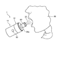
- (About wearing chemical pack 20) 5 shows the mesh nebulizer 1 in a state where the opening 30b of the holder member 30 of the mesh nebulizer 1 of FIG. Are shown.
- a user who intends to use the mesh nebulizer 1 rotates the outer peripheral wall 31 of the main body 10 in the direction indicated by the arrow E as shown in FIG.
- the holder member 30 formed with the first screw element 33 engaged with the second screw element 34 is raised in the direction indicated by the arrow F, and the opening 30b closed by the outer peripheral wall 31 is exposed.
- the user puts the medicinal solution pack 20 in the concave portion 16 of the main body 10 through the opening 30b and holds it.
- the user rotates the outer peripheral wall 31 of the main body 10 in the direction opposite to the arrow E in a state where the chemical pack 20 is mounted in the recess 16.
- the holder member 30 formed with the first screw element 33 engaged with the second screw element 34 is lowered in the direction opposite to the arrow F, and the opening 30 b is arranged inside the outer peripheral wall 31. That is, the opening 30 b is closed by the outer peripheral wall 31.
- the outer peripheral wall 31 When the chemical pack 20 is attached to the main body 10, the outer peripheral wall 31 is rotated around the inner peripheral wall 16c, and the holder member 30 is lowered with respect to the inner peripheral wall 16c by the lifting mechanism 100. Then, the bottom surface 24 c of the concave portion 17 of the chemical solution storage member 24 of the chemical solution pack 20 approaches and comes into contact with the vibration surface 43. Then, the material having the extensibility of the bottom surface 24 c extends, and the vibration surface 43 approaches the mesh portion 24 a of the lid member 21.
- the chemical pack 20 When the chemical pack 20 is removed from the main body 10, the outer peripheral wall 31 is rotated around the inner peripheral wall 16 c, and when the holder member 30 is raised relative to the inner peripheral wall 16 c by the lifting mechanism 100, the chemical pack 20 vibrates. Separate from the surface 43.
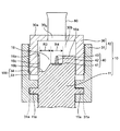
- FIG. 6 is a view showing a part of a longitudinal section when the mesh nebulizer 1 of FIG. 5 is viewed from the right side (the direction indicated by the arrow G in FIG. 5).
- FIG. 6 shows the mesh nebulizer 1 in a state where the chemical pack 20 is mounted in the recess 16 of the main body 10 of the mesh nebulizer 1.
- the user attaches the chemical pack 20 to the recess 16 of the main body 10 through the opening 30 b.
- the flange portion 21 a of the lid member 21 of the drug solution pack 20 is supported by the upper edge 16 a of the inner peripheral wall 16 c of the main body 10.
- the chemical solution 23 in the first region of FIG. 2B moves along the bottom surface 24 c of the concave portion 17 of the chemical solution pack 20. It is supplied toward the vibration surface 43. That is, the chemical solution is supplied between the vibration surface 43 and the mesh portion 24a.
- a driving voltage is applied to the ultrasonic transducer 41 of the vibrating unit 40 and the vibrating surface 43 is vibrated. Thereby, the chemical
- the chemical pack 20 is removed from the main body 10 and discarded.
- the mesh type nebulizer 1 of the present invention is equipped with a new chemical solution pack 20 every time it is used, it is not necessary to clean the mesh portion 24a. Therefore, it is hygienic and easy to clean for the user without reducing the spray efficiency. Furthermore, since the new mesh portion 24a is used every time it is used, it is hygienic and the spray efficiency does not decrease.
Landscapes
- Health & Medical Sciences (AREA)
- Engineering & Computer Science (AREA)
- Animal Behavior & Ethology (AREA)
- Anesthesiology (AREA)
- Biomedical Technology (AREA)
- Heart & Thoracic Surgery (AREA)
- Hematology (AREA)
- Life Sciences & Earth Sciences (AREA)
- General Health & Medical Sciences (AREA)
- Public Health (AREA)
- Veterinary Medicine (AREA)
- Pulmonology (AREA)
- Bioinformatics & Cheminformatics (AREA)
- Special Spraying Apparatus (AREA)
- Containers And Packaging Bodies Having A Special Means To Remove Contents (AREA)
Priority Applications (3)
| Application Number | Priority Date | Filing Date | Title |
|---|---|---|---|
| CN201780055070.9A CN109689138B (zh) | 2016-09-20 | 2017-08-09 | 网眼式喷雾器和药液包 |
| DE112017004699.8T DE112017004699T5 (de) | 2016-09-20 | 2017-08-09 | Vernebler vom Netztyp und medizinische Flüssigkeitspackung |
| US16/280,080 US11318263B2 (en) | 2016-09-20 | 2019-02-20 | Mesh nebulizer and medicinal liquid pack |
Applications Claiming Priority (2)
| Application Number | Priority Date | Filing Date | Title |
|---|---|---|---|
| JP2016183462A JP6776761B2 (ja) | 2016-09-20 | 2016-09-20 | メッシュ式ネブライザおよび薬液パック |
| JP2016-183462 | 2016-09-20 |
Related Child Applications (1)
| Application Number | Title | Priority Date | Filing Date |
|---|---|---|---|
| US16/280,080 Continuation US11318263B2 (en) | 2016-09-20 | 2019-02-20 | Mesh nebulizer and medicinal liquid pack |
Publications (1)
| Publication Number | Publication Date |
|---|---|
| WO2018055940A1 true WO2018055940A1 (ja) | 2018-03-29 |
Family
ID=61689446
Family Applications (1)
| Application Number | Title | Priority Date | Filing Date |
|---|---|---|---|
| PCT/JP2017/028910 Ceased WO2018055940A1 (ja) | 2016-09-20 | 2017-08-09 | メッシュ式ネブライザおよび薬液パック |
Country Status (5)
| Country | Link |
|---|---|
| US (1) | US11318263B2 (enExample) |
| JP (1) | JP6776761B2 (enExample) |
| CN (1) | CN109689138B (enExample) |
| DE (1) | DE112017004699T5 (enExample) |
| WO (1) | WO2018055940A1 (enExample) |
Families Citing this family (2)
| Publication number | Priority date | Publication date | Assignee | Title |
|---|---|---|---|---|
| CN110605194A (zh) * | 2019-10-29 | 2019-12-24 | 浙江大悦生物科技有限公司 | 一种倒流式可分次加注指定剂量雾化液的可储液电子雾化器 |
| WO2024076894A1 (en) * | 2022-10-04 | 2024-04-11 | Simon Baek | Compact telescoping spacer with double-barrel for metered dose inhaler |
Citations (5)
| Publication number | Priority date | Publication date | Assignee | Title |
|---|---|---|---|---|
| JP2010119845A (ja) * | 2008-11-24 | 2010-06-03 | Ep Systems Sa Microflow Division | 噴霧器 |
| US20120259277A1 (en) * | 2011-04-06 | 2012-10-11 | Mystic Pharmaceuticals, Inc. | Medical devices for dispensing powders |
| US8353287B1 (en) * | 2006-04-20 | 2013-01-15 | Ric Investments, Llc | Disposable drug solution cup for an ultrasonic nebulizer |
| JP2013252261A (ja) * | 2012-06-06 | 2013-12-19 | Dainippon Printing Co Ltd | 噴霧デバイス用の液体カートリッジ、液体カートリッジパッケージ、噴霧デバイス及び噴霧デバイス用のメッシュ付容器 |
| JP2014004211A (ja) * | 2012-06-26 | 2014-01-16 | Omron Healthcare Co Ltd | 液体噴霧装置 |
Family Cites Families (16)
| Publication number | Priority date | Publication date | Assignee | Title |
|---|---|---|---|---|
| EP0516565B1 (en) * | 1991-05-27 | 1996-04-24 | TDK Corporation | An ultrasonic wave nebulizer |
| FR2705911B1 (fr) * | 1993-06-02 | 1995-08-11 | Oreal | Appareil de nébulisation piézoélectrique. |
| EP2165771B1 (en) * | 2000-10-05 | 2012-01-18 | Omron Healthcare Co., Ltd. | Liquid spray device |
| CN1840211A (zh) * | 2000-10-05 | 2006-10-04 | 欧姆龙健康医疗事业株式会社 | 液体雾化装置 |
| JP2003102837A (ja) * | 2001-09-28 | 2003-04-08 | Omron Corp | 霧化装置用吸入補助具およびこれを備えた霧化装置 |
| EP1604701B1 (en) * | 2004-06-09 | 2010-12-15 | Microflow Engineering SA | Improved modular liquid spray system |
| JP5267245B2 (ja) * | 2009-03-17 | 2013-08-21 | オムロンヘルスケア株式会社 | ネブライザ、および、ネブライザに着脱可能な機能ユニット |
| JP5652790B2 (ja) * | 2011-09-22 | 2015-01-14 | オムロンヘルスケア株式会社 | 液体噴霧装置 |
| GB2500588B (en) * | 2012-03-24 | 2017-02-01 | Rhinocare Ltd | Systems and methods of hyperthermal treatment |
| JP2014004208A (ja) | 2012-06-26 | 2014-01-16 | Omron Healthcare Co Ltd | 液体噴霧装置 |
| CN103933645B (zh) * | 2013-01-21 | 2016-01-13 | 胡生彬 | 有效控制超微细雾化颗粒输出的医疗微网片雾化器 |
| EP2996748B1 (en) * | 2013-05-17 | 2018-09-26 | Koninklijke Philips N.V. | Substance delivery module |
| WO2015022436A1 (en) * | 2013-08-16 | 2015-02-19 | Vectura Gmbh | Dosing system for an inhalation device |
| TWI539978B (zh) * | 2013-09-13 | 2016-07-01 | 台達電子工業股份有限公司 | 微霧化裝置及其給藥室模組 |
| JP5928425B2 (ja) * | 2013-09-24 | 2016-06-01 | オムロンヘルスケア株式会社 | ネブライザ用メッシュ選定方法、装置、及びプログラム |
| EP3247435B1 (en) * | 2015-01-23 | 2021-03-10 | William Tan | Ultrasonic vaporizing element |
-
2016
- 2016-09-20 JP JP2016183462A patent/JP6776761B2/ja active Active
-
2017
- 2017-08-09 WO PCT/JP2017/028910 patent/WO2018055940A1/ja not_active Ceased
- 2017-08-09 DE DE112017004699.8T patent/DE112017004699T5/de active Pending
- 2017-08-09 CN CN201780055070.9A patent/CN109689138B/zh active Active
-
2019
- 2019-02-20 US US16/280,080 patent/US11318263B2/en active Active
Patent Citations (5)
| Publication number | Priority date | Publication date | Assignee | Title |
|---|---|---|---|---|
| US8353287B1 (en) * | 2006-04-20 | 2013-01-15 | Ric Investments, Llc | Disposable drug solution cup for an ultrasonic nebulizer |
| JP2010119845A (ja) * | 2008-11-24 | 2010-06-03 | Ep Systems Sa Microflow Division | 噴霧器 |
| US20120259277A1 (en) * | 2011-04-06 | 2012-10-11 | Mystic Pharmaceuticals, Inc. | Medical devices for dispensing powders |
| JP2013252261A (ja) * | 2012-06-06 | 2013-12-19 | Dainippon Printing Co Ltd | 噴霧デバイス用の液体カートリッジ、液体カートリッジパッケージ、噴霧デバイス及び噴霧デバイス用のメッシュ付容器 |
| JP2014004211A (ja) * | 2012-06-26 | 2014-01-16 | Omron Healthcare Co Ltd | 液体噴霧装置 |
Also Published As
| Publication number | Publication date |
|---|---|
| US20190175845A1 (en) | 2019-06-13 |
| DE112017004699T5 (de) | 2019-07-04 |
| US11318263B2 (en) | 2022-05-03 |
| CN109689138B (zh) | 2021-07-06 |
| JP2018046945A (ja) | 2018-03-29 |
| JP6776761B2 (ja) | 2020-10-28 |
| CN109689138A (zh) | 2019-04-26 |
Similar Documents
| Publication | Publication Date | Title |
|---|---|---|
| US20160279352A1 (en) | Portable high frequency ultrasonic nebulizer for the whole respiratory tract drug delivery | |
| KR0152086B1 (ko) | 분배장치 | |
| KR102291016B1 (ko) | 살균 충전식 얼굴용 브러시 | |
| WO2018047508A1 (ja) | メッシュ式ネブライザ | |
| CN102755684A (zh) | 眼用雾化装置 | |
| CN203029818U (zh) | 一种便携式喷雾器装置 | |
| JP2018038668A5 (enExample) | ||
| US10926045B2 (en) | Mesh nebulizer and replacement member | |
| CN104918593A (zh) | 光疗皮肤装置 | |
| JP2019076243A (ja) | メッシュ式ネブライザおよび交換部材 | |
| WO2018055940A1 (ja) | メッシュ式ネブライザおよび薬液パック | |
| JP2018046945A5 (enExample) | ||
| JP2017202026A5 (enExample) | ||
| TWM536948U (zh) | 微霧化裝置及微霧化器 | |
| JP7030771B2 (ja) | エアロゾル化装置及びエアロゾル薬物送達装置 | |
| ES2975768T3 (es) | Método y recipiente para limpiar la membrana de un nebulizador | |
| JP6701935B2 (ja) | メッシュ式ネブライザおよび交換セット | |
| US20060253154A1 (en) | Teething device | |
| CN202446335U (zh) | 眼用雾化装置 | |
| JP2019025196A (ja) | 噴霧式美容器 | |
| TWM528175U (zh) | 便攜式噴霧器 | |
| KR100985761B1 (ko) | 초음파소자 일체형 메쉬와 실리콘 홀더와 약제통의 결합구조 | |
| KR100591522B1 (ko) | 화장용 파우더 용기 | |
| BR112020007587B1 (pt) | Membro de substituição, e, nebulizador do tipo malha | |
| JP2019051217A (ja) | メッシュ式ネブライザ |
Legal Events
| Date | Code | Title | Description |
|---|---|---|---|
| 121 | Ep: the epo has been informed by wipo that ep was designated in this application |
Ref document number: 17852721 Country of ref document: EP Kind code of ref document: A1 |
|
| 122 | Ep: pct application non-entry in european phase |
Ref document number: 17852721 Country of ref document: EP Kind code of ref document: A1 |