WO2018055696A1 - 作業車両および油圧制御方法 - Google Patents
作業車両および油圧制御方法 Download PDFInfo
- Publication number
- WO2018055696A1 WO2018055696A1 PCT/JP2016/077849 JP2016077849W WO2018055696A1 WO 2018055696 A1 WO2018055696 A1 WO 2018055696A1 JP 2016077849 W JP2016077849 W JP 2016077849W WO 2018055696 A1 WO2018055696 A1 WO 2018055696A1
- Authority
- WO
- WIPO (PCT)
- Prior art keywords
- hydraulic
- valve
- hydraulic pump
- pressure
- merging
- Prior art date
- Legal status (The legal status is an assumption and is not a legal conclusion. Google has not performed a legal analysis and makes no representation as to the accuracy of the status listed.)
- Ceased
Links
Images





Classifications
-
- E—FIXED CONSTRUCTIONS
- E02—HYDRAULIC ENGINEERING; FOUNDATIONS; SOIL SHIFTING
- E02F—DREDGING; SOIL-SHIFTING
- E02F9/00—Component parts of dredgers or soil-shifting machines, not restricted to one of the kinds covered by groups E02F3/00 - E02F7/00
- E02F9/20—Drives; Control devices
- E02F9/22—Hydraulic or pneumatic drives
- E02F9/2221—Control of flow rate; Load sensing arrangements
- E02F9/2225—Control of flow rate; Load sensing arrangements using pressure-compensating valves
- E02F9/2228—Control of flow rate; Load sensing arrangements using pressure-compensating valves including an electronic controller
-
- F—MECHANICAL ENGINEERING; LIGHTING; HEATING; WEAPONS; BLASTING
- F15—FLUID-PRESSURE ACTUATORS; HYDRAULICS OR PNEUMATICS IN GENERAL
- F15B—SYSTEMS ACTING BY MEANS OF FLUIDS IN GENERAL; FLUID-PRESSURE ACTUATORS, e.g. SERVOMOTORS; DETAILS OF FLUID-PRESSURE SYSTEMS, NOT OTHERWISE PROVIDED FOR
- F15B11/00—Servomotor systems without provision for follow-up action; Circuits therefor
- F15B11/16—Servomotor systems without provision for follow-up action; Circuits therefor with two or more servomotors
- F15B11/17—Servomotor systems without provision for follow-up action; Circuits therefor with two or more servomotors using two or more pumps
-
- E—FIXED CONSTRUCTIONS
- E02—HYDRAULIC ENGINEERING; FOUNDATIONS; SOIL SHIFTING
- E02F—DREDGING; SOIL-SHIFTING
- E02F9/00—Component parts of dredgers or soil-shifting machines, not restricted to one of the kinds covered by groups E02F3/00 - E02F7/00
- E02F9/20—Drives; Control devices
- E02F9/22—Hydraulic or pneumatic drives
- E02F9/2221—Control of flow rate; Load sensing arrangements
-
- E—FIXED CONSTRUCTIONS
- E02—HYDRAULIC ENGINEERING; FOUNDATIONS; SOIL SHIFTING
- E02F—DREDGING; SOIL-SHIFTING
- E02F3/00—Dredgers; Soil-shifting machines
- E02F3/04—Dredgers; Soil-shifting machines mechanically-driven
- E02F3/28—Dredgers; Soil-shifting machines mechanically-driven with digging tools mounted on a dipper- or bucket-arm, i.e. there is either one arm or a pair of arms, e.g. dippers, buckets
- E02F3/30—Dredgers; Soil-shifting machines mechanically-driven with digging tools mounted on a dipper- or bucket-arm, i.e. there is either one arm or a pair of arms, e.g. dippers, buckets with a dipper-arm pivoted on a cantilever beam, i.e. boom
- E02F3/32—Dredgers; Soil-shifting machines mechanically-driven with digging tools mounted on a dipper- or bucket-arm, i.e. there is either one arm or a pair of arms, e.g. dippers, buckets with a dipper-arm pivoted on a cantilever beam, i.e. boom working downwardly and towards the machine, e.g. with backhoes
-
- E—FIXED CONSTRUCTIONS
- E02—HYDRAULIC ENGINEERING; FOUNDATIONS; SOIL SHIFTING
- E02F—DREDGING; SOIL-SHIFTING
- E02F3/00—Dredgers; Soil-shifting machines
- E02F3/04—Dredgers; Soil-shifting machines mechanically-driven
- E02F3/28—Dredgers; Soil-shifting machines mechanically-driven with digging tools mounted on a dipper- or bucket-arm, i.e. there is either one arm or a pair of arms, e.g. dippers, buckets
- E02F3/36—Component parts
- E02F3/42—Drives for dippers, buckets, dipper-arms or bucket-arms
- E02F3/425—Drive systems for dipper-arms, backhoes or the like
-
- E—FIXED CONSTRUCTIONS
- E02—HYDRAULIC ENGINEERING; FOUNDATIONS; SOIL SHIFTING
- E02F—DREDGING; SOIL-SHIFTING
- E02F3/00—Dredgers; Soil-shifting machines
- E02F3/04—Dredgers; Soil-shifting machines mechanically-driven
- E02F3/28—Dredgers; Soil-shifting machines mechanically-driven with digging tools mounted on a dipper- or bucket-arm, i.e. there is either one arm or a pair of arms, e.g. dippers, buckets
- E02F3/36—Component parts
- E02F3/42—Drives for dippers, buckets, dipper-arms or bucket-arms
- E02F3/43—Control of dipper or bucket position; Control of sequence of drive operations
- E02F3/435—Control of dipper or bucket position; Control of sequence of drive operations for dipper-arms, backhoes or the like
-
- E—FIXED CONSTRUCTIONS
- E02—HYDRAULIC ENGINEERING; FOUNDATIONS; SOIL SHIFTING
- E02F—DREDGING; SOIL-SHIFTING
- E02F9/00—Component parts of dredgers or soil-shifting machines, not restricted to one of the kinds covered by groups E02F3/00 - E02F7/00
- E02F9/20—Drives; Control devices
- E02F9/22—Hydraulic or pneumatic drives
-
- E—FIXED CONSTRUCTIONS
- E02—HYDRAULIC ENGINEERING; FOUNDATIONS; SOIL SHIFTING
- E02F—DREDGING; SOIL-SHIFTING
- E02F9/00—Component parts of dredgers or soil-shifting machines, not restricted to one of the kinds covered by groups E02F3/00 - E02F7/00
- E02F9/20—Drives; Control devices
- E02F9/22—Hydraulic or pneumatic drives
- E02F9/2221—Control of flow rate; Load sensing arrangements
- E02F9/2232—Control of flow rate; Load sensing arrangements using one or more variable displacement pumps
- E02F9/2235—Control of flow rate; Load sensing arrangements using one or more variable displacement pumps including an electronic controller
-
- E—FIXED CONSTRUCTIONS
- E02—HYDRAULIC ENGINEERING; FOUNDATIONS; SOIL SHIFTING
- E02F—DREDGING; SOIL-SHIFTING
- E02F9/00—Component parts of dredgers or soil-shifting machines, not restricted to one of the kinds covered by groups E02F3/00 - E02F7/00
- E02F9/20—Drives; Control devices
- E02F9/22—Hydraulic or pneumatic drives
- E02F9/2221—Control of flow rate; Load sensing arrangements
- E02F9/2239—Control of flow rate; Load sensing arrangements using two or more pumps with cross-assistance
- E02F9/2242—Control of flow rate; Load sensing arrangements using two or more pumps with cross-assistance including an electronic controller
-
- E—FIXED CONSTRUCTIONS
- E02—HYDRAULIC ENGINEERING; FOUNDATIONS; SOIL SHIFTING
- E02F—DREDGING; SOIL-SHIFTING
- E02F9/00—Component parts of dredgers or soil-shifting machines, not restricted to one of the kinds covered by groups E02F3/00 - E02F7/00
- E02F9/20—Drives; Control devices
- E02F9/22—Hydraulic or pneumatic drives
- E02F9/2264—Arrangements or adaptations of elements for hydraulic drives
- E02F9/2267—Valves or distributors
-
- E—FIXED CONSTRUCTIONS
- E02—HYDRAULIC ENGINEERING; FOUNDATIONS; SOIL SHIFTING
- E02F—DREDGING; SOIL-SHIFTING
- E02F9/00—Component parts of dredgers or soil-shifting machines, not restricted to one of the kinds covered by groups E02F3/00 - E02F7/00
- E02F9/20—Drives; Control devices
- E02F9/22—Hydraulic or pneumatic drives
- E02F9/2264—Arrangements or adaptations of elements for hydraulic drives
- E02F9/2271—Actuators and supports therefor and protection therefor
-
- E—FIXED CONSTRUCTIONS
- E02—HYDRAULIC ENGINEERING; FOUNDATIONS; SOIL SHIFTING
- E02F—DREDGING; SOIL-SHIFTING
- E02F9/00—Component parts of dredgers or soil-shifting machines, not restricted to one of the kinds covered by groups E02F3/00 - E02F7/00
- E02F9/20—Drives; Control devices
- E02F9/22—Hydraulic or pneumatic drives
- E02F9/2278—Hydraulic circuits
- E02F9/2292—Systems with two or more pumps
-
- E—FIXED CONSTRUCTIONS
- E02—HYDRAULIC ENGINEERING; FOUNDATIONS; SOIL SHIFTING
- E02F—DREDGING; SOIL-SHIFTING
- E02F9/00—Component parts of dredgers or soil-shifting machines, not restricted to one of the kinds covered by groups E02F3/00 - E02F7/00
- E02F9/20—Drives; Control devices
- E02F9/22—Hydraulic or pneumatic drives
- E02F9/2278—Hydraulic circuits
- E02F9/2296—Systems with a variable displacement pump
-
- F—MECHANICAL ENGINEERING; LIGHTING; HEATING; WEAPONS; BLASTING
- F15—FLUID-PRESSURE ACTUATORS; HYDRAULICS OR PNEUMATICS IN GENERAL
- F15B—SYSTEMS ACTING BY MEANS OF FLUIDS IN GENERAL; FLUID-PRESSURE ACTUATORS, e.g. SERVOMOTORS; DETAILS OF FLUID-PRESSURE SYSTEMS, NOT OTHERWISE PROVIDED FOR
- F15B11/00—Servomotor systems without provision for follow-up action; Circuits therefor
- F15B11/02—Systems essentially incorporating special features for controlling the speed or actuating force of an output member
-
- F—MECHANICAL ENGINEERING; LIGHTING; HEATING; WEAPONS; BLASTING
- F15—FLUID-PRESSURE ACTUATORS; HYDRAULICS OR PNEUMATICS IN GENERAL
- F15B—SYSTEMS ACTING BY MEANS OF FLUIDS IN GENERAL; FLUID-PRESSURE ACTUATORS, e.g. SERVOMOTORS; DETAILS OF FLUID-PRESSURE SYSTEMS, NOT OTHERWISE PROVIDED FOR
- F15B13/00—Details of servomotor systems ; Valves for servomotor systems
- F15B13/02—Fluid distribution or supply devices characterised by their adaptation to the control of servomotors
-
- F—MECHANICAL ENGINEERING; LIGHTING; HEATING; WEAPONS; BLASTING
- F15—FLUID-PRESSURE ACTUATORS; HYDRAULICS OR PNEUMATICS IN GENERAL
- F15B—SYSTEMS ACTING BY MEANS OF FLUIDS IN GENERAL; FLUID-PRESSURE ACTUATORS, e.g. SERVOMOTORS; DETAILS OF FLUID-PRESSURE SYSTEMS, NOT OTHERWISE PROVIDED FOR
- F15B15/00—Fluid-actuated devices for displacing a member from one position to another; Gearing associated therewith
- F15B15/02—Mechanical layout characterised by the means for converting the movement of the fluid-actuated element into movement of the finally-operated member
-
- F—MECHANICAL ENGINEERING; LIGHTING; HEATING; WEAPONS; BLASTING
- F15—FLUID-PRESSURE ACTUATORS; HYDRAULICS OR PNEUMATICS IN GENERAL
- F15B—SYSTEMS ACTING BY MEANS OF FLUIDS IN GENERAL; FLUID-PRESSURE ACTUATORS, e.g. SERVOMOTORS; DETAILS OF FLUID-PRESSURE SYSTEMS, NOT OTHERWISE PROVIDED FOR
- F15B21/00—Common features of fluid actuator systems; Fluid-pressure actuator systems or details thereof, not covered by any other group of this subclass
- F15B21/001—Servomotor systems with fluidic control
-
- E—FIXED CONSTRUCTIONS
- E02—HYDRAULIC ENGINEERING; FOUNDATIONS; SOIL SHIFTING
- E02F—DREDGING; SOIL-SHIFTING
- E02F9/00—Component parts of dredgers or soil-shifting machines, not restricted to one of the kinds covered by groups E02F3/00 - E02F7/00
- E02F9/20—Drives; Control devices
- E02F9/22—Hydraulic or pneumatic drives
- E02F9/2278—Hydraulic circuits
- E02F9/2285—Pilot-operated systems
-
- F—MECHANICAL ENGINEERING; LIGHTING; HEATING; WEAPONS; BLASTING
- F15—FLUID-PRESSURE ACTUATORS; HYDRAULICS OR PNEUMATICS IN GENERAL
- F15B—SYSTEMS ACTING BY MEANS OF FLUIDS IN GENERAL; FLUID-PRESSURE ACTUATORS, e.g. SERVOMOTORS; DETAILS OF FLUID-PRESSURE SYSTEMS, NOT OTHERWISE PROVIDED FOR
- F15B2211/00—Circuits for servomotor systems
- F15B2211/20—Fluid pressure source, e.g. accumulator or variable axial piston pump
- F15B2211/205—Systems with pumps
- F15B2211/20576—Systems with pumps with multiple pumps
-
- F—MECHANICAL ENGINEERING; LIGHTING; HEATING; WEAPONS; BLASTING
- F15—FLUID-PRESSURE ACTUATORS; HYDRAULICS OR PNEUMATICS IN GENERAL
- F15B—SYSTEMS ACTING BY MEANS OF FLUIDS IN GENERAL; FLUID-PRESSURE ACTUATORS, e.g. SERVOMOTORS; DETAILS OF FLUID-PRESSURE SYSTEMS, NOT OTHERWISE PROVIDED FOR
- F15B2211/00—Circuits for servomotor systems
- F15B2211/30—Directional control
- F15B2211/305—Directional control characterised by the type of valves
- F15B2211/3056—Assemblies of multiple valves
- F15B2211/3059—Assemblies of multiple valves having multiple valves for multiple output members
- F15B2211/30595—Assemblies of multiple valves having multiple valves for multiple output members with additional valves between the groups of valves for multiple output members
-
- F—MECHANICAL ENGINEERING; LIGHTING; HEATING; WEAPONS; BLASTING
- F15—FLUID-PRESSURE ACTUATORS; HYDRAULICS OR PNEUMATICS IN GENERAL
- F15B—SYSTEMS ACTING BY MEANS OF FLUIDS IN GENERAL; FLUID-PRESSURE ACTUATORS, e.g. SERVOMOTORS; DETAILS OF FLUID-PRESSURE SYSTEMS, NOT OTHERWISE PROVIDED FOR
- F15B2211/00—Circuits for servomotor systems
- F15B2211/40—Flow control
- F15B2211/405—Flow control characterised by the type of flow control means or valve
-
- F—MECHANICAL ENGINEERING; LIGHTING; HEATING; WEAPONS; BLASTING
- F15—FLUID-PRESSURE ACTUATORS; HYDRAULICS OR PNEUMATICS IN GENERAL
- F15B—SYSTEMS ACTING BY MEANS OF FLUIDS IN GENERAL; FLUID-PRESSURE ACTUATORS, e.g. SERVOMOTORS; DETAILS OF FLUID-PRESSURE SYSTEMS, NOT OTHERWISE PROVIDED FOR
- F15B2211/00—Circuits for servomotor systems
- F15B2211/40—Flow control
- F15B2211/415—Flow control characterised by the connections of the flow control means in the circuit
- F15B2211/41509—Flow control characterised by the connections of the flow control means in the circuit being connected to a pressure source and a directional control valve
- F15B2211/41518—Flow control characterised by the connections of the flow control means in the circuit being connected to a pressure source and a directional control valve being connected to multiple pressure sources
-
- F—MECHANICAL ENGINEERING; LIGHTING; HEATING; WEAPONS; BLASTING
- F15—FLUID-PRESSURE ACTUATORS; HYDRAULICS OR PNEUMATICS IN GENERAL
- F15B—SYSTEMS ACTING BY MEANS OF FLUIDS IN GENERAL; FLUID-PRESSURE ACTUATORS, e.g. SERVOMOTORS; DETAILS OF FLUID-PRESSURE SYSTEMS, NOT OTHERWISE PROVIDED FOR
- F15B2211/00—Circuits for servomotor systems
- F15B2211/70—Output members, e.g. hydraulic motors or cylinders or control therefor
- F15B2211/71—Multiple output members, e.g. multiple hydraulic motors or cylinders
- F15B2211/7142—Multiple output members, e.g. multiple hydraulic motors or cylinders the output members being arranged in multiple groups
Definitions
- the present invention relates to a work vehicle and a hydraulic control method for the work vehicle.
- Patent Document 1 discloses a hydraulic control system for the purpose of preventing pressure loss of a hydraulic pump.
- the hydraulic control system includes a first hydraulic pump, a second hydraulic pump, an arm cylinder, a bucket cylinder, an arm operating device, a bucket operating device, a first arm control valve, and a second arm.
- a control valve, a bucket control valve, and a merging release valve are provided.
- the first arm control valve is disposed in the flow path between the first hydraulic pump and the arm cylinder, and controls the start, stop, and direction switching of the arm cylinder when switched by the operation of the arm operating device.
- the second arm control valve is disposed in a flow path between the second hydraulic pump and the arm cylinder, and is switched when a control signal due to operation of the arm operating device exceeds a set value, thereby Supply pump discharge flow rate to the arm cylinder.
- the bucket control valve is disposed in the flow path between the second hydraulic pump and the bucket cylinder, and controls the start, stop, and direction switching of the bucket cylinder when switched by operation of the bucket operating device.
- the merge release valve is disposed in a flow path between the second hydraulic pump and the second arm control valve.
- the merging function is canceled during the combined operation of excavation work by operating the arm and bucket at the same time.
- the arm cylinder is driven by the supply of hydraulic oil from only the first hydraulic pump of the first hydraulic pump and the second hydraulic pump.
- the bucket cylinder is driven by supplying hydraulic oil only from the second hydraulic pump.
- Patent Document 2 discloses a flow merging device in heavy equipment including a first hydraulic pump and a second hydraulic pump.
- the flow rate merger includes a pilot flow path opening / closing valve that opens and closes the pilot flow path by a predetermined external signal.
- the merging function with the first hydraulic pump side actuator is selectively performed according to the operating state of the second hydraulic pump side actuator. With such a configuration, the flow merging device attempts to improve the workability of the equipment by smoothly performing the combined operation of the actuator.
- Patent Document 3 discloses a hydraulic control device capable of improving operability and work efficiency by suppressing flow fluctuations occurring before and after switching of a merging and merging valve. Yes.
- This hydraulic control device can accurately determine the switching timing of the branching valve. Therefore, according to the hydraulic control device, it is possible to suppress the energy loss due to the pressure loss of the pressure compensation valve and improve the working efficiency during the combined operation of the plurality of hydraulic actuators.
- the present disclosure has been made in view of the above-described problems, and provides a work vehicle capable of efficiently performing excavation work by increasing the excavation speed of the bucket and a hydraulic control method in the work vehicle.
- the purpose is to do.
- a work vehicle discharges by a bucket, an arm, a first hydraulic pump and a second hydraulic pump that discharge hydraulic fluid, and a first hydraulic pump to drive the bucket.
- the first oil passage for flowing the hydraulic oil, the second oil passage for flowing the hydraulic oil discharged by the second hydraulic pump to drive the arm, the first oil passage, and the second oil A merging valve that switches between a merging position that communicates with the passage and a divergence position that separates the first oil passage and the second oil passage, and the amount of hydraulic oil discharged by the first hydraulic pump; And a controller that controls the amount of hydraulic oil discharged from the second hydraulic pump and the operation of the merging / combining valve.
- the controller switches the merging valve from the merging position to the divergence position.
- the controller is configured such that when the pump pressure of the first hydraulic pump is equal to or higher than the first predetermined value, the amount of hydraulic oil discharged from the first hydraulic pump is larger than the amount of hydraulic oil discharged from the second hydraulic pump.
- the first oil passage and the second oil The road is separated. Further, when the pump pressure of the first hydraulic pump is equal to or higher than the first predetermined value, the amount of hydraulic oil discharged from the first hydraulic pump is larger than the amount of hydraulic oil discharged from the second hydraulic pump. . For this reason, the amount of oil supplied to the bucket side is greater than the amount of oil supplied to the arm side. Therefore, a decrease in bucket excavation speed can be suppressed. Therefore, excavation work can be performed more efficiently than in a configuration in which the amount of oil supplied to the arm side and the amount of oil supplied to the bucket side are the same.
- the excavation speed of the bucket decreases when either the pump pressure of the first hydraulic pump or the pump pressure of the second hydraulic pump is equal to or higher than the second predetermined value which is smaller than the first predetermined value. Can be suppressed.
- the pump pressure increases as the load on the bucket side increases. Therefore, by increasing the ratio of the amount of hydraulic oil discharged from the first hydraulic pump to the amount of hydraulic oil discharged from the second hydraulic pump as the value of the detection result by the sensor increases, the bucket Even if the load on the side gradually increases, the decrease in the excavation speed of the bucket can be suppressed.
- the controller is configured such that either the pump pressure of the first hydraulic pump or the pump pressure of the second hydraulic pump is smaller than the first predetermined value.
- the branching valve is switched from the branching position to the joining position.
- the pump pressure increases by the difference between the first predetermined value and the third predetermined value. Necessary. Therefore, it is possible to prevent a situation in which the flow returns to the diversion position instantaneously after the diversion position returns to the merge position.
- the controller sets the amount of hydraulic oil discharged by the first hydraulic pump after switching the merging valve from the merging position to the merging position until the merging valve is switched from the merging position to the merging position.
- the first hydraulic pump and the second hydraulic pump are controlled so as to be larger than the amount of hydraulic oil discharged by the second hydraulic pump.
- the work vehicle includes a first actuator that drives the bucket, a second actuator that drives the arm, a first actuator that is connected to the first oil passage and supplies hydraulic oil to the first actuator.
- the apparatus further includes a first pressure compensation valve provided between the main operation valve and a second pressure compensation valve provided between the second actuator and the second main operation valve. In the second pressure compensation valve, the differential pressure between the inlet port and the output port of the second main operation valve is greater than the differential pressure between the inlet port and the output port of the first main operation valve.
- a hydraulic control method includes a first oil passage for flowing hydraulic oil discharged by a first hydraulic pump for driving a bucket, and a second hydraulic pressure for driving an arm. From one of the merging position where the second oil passage through which the hydraulic oil discharged by the pump is communicated and the diversion position where the first oil passage and the second oil passage are separated from each other It is executed in a work vehicle provided with a merging and merging valve that switches to the position.
- the hydraulic control method includes a step of switching the junction valve from the junction position to the branch position, and the amount of hydraulic oil discharged from the first hydraulic pump is larger than the amount of hydraulic oil discharged from the second hydraulic pump. And a step of controlling the first hydraulic pump and the second hydraulic pump.
- the first oil passage and the second oil The road is separated. Further, when the pump pressure of the first hydraulic pump is equal to or higher than the first predetermined value, the amount of hydraulic oil discharged from the first hydraulic pump is larger than the amount of hydraulic oil discharged from the second hydraulic pump. . For this reason, the amount of oil supplied to the bucket side is greater than the amount of oil supplied to the arm side. Therefore, it can suppress that the excavation speed of a bucket falls. Therefore, excavation work can be performed more efficiently than in a configuration in which the amount of oil supplied to the arm side and the amount of oil supplied to the bucket side are the same.
- FIG. 1 is a diagram illustrating an appearance of a work vehicle 100 based on the embodiment. As shown in FIG. 1, the working vehicle 100 will be described mainly using a hydraulic excavator as an example in this example.
- Work vehicle 100 mainly includes a traveling body 101, a turning body 103, and a work implement 104.
- the work vehicle main body includes a traveling body 101 and a turning body 103.
- the traveling body 101 has a pair of left and right crawler belts.
- the swivel body 103 is mounted so as to be able to swivel via a swivel mechanism at the top of the traveling body 101.
- the work machine 104 is pivotally supported by the swing body 103 so as to be operable in the vertical direction, and performs work such as excavation of earth and sand.
- Work implement 104 includes a boom 105, an arm 106, and a bucket 107.
- a base portion of the boom 105 is movably connected to the swing body 103.
- the arm 106 is movably connected to the tip of the boom 105.
- Bucket 107 is movably connected to the tip of arm 106.
- the swivel body 103 includes a cab 108 and the like.
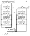
- FIG. 2 is a diagram showing an outline of the hydraulic system 109 mounted on the work vehicle 100.
- the hydraulic system 109 includes a first hydraulic pump 2, a second hydraulic pump 3, discharge oil passages 10 and 11, and a communication passage 12.
- the hydraulic system 109 includes a main operation valve 51 for the boom, a main operation valve 52 for the crawler on the left side of the traveling body 101, a main operation valve 5 for the bucket, and a main operation valve 53 for the boom Hi (High).
- the main operation valve 61 for turning, the main operation valve 62 for the crawler track on the right side of the traveling body 101, the main operation valve 8 for the arm, the relief valves 54 and 63, the unload valves 55 and 64,
- a merging valve 13 is further provided.
- the discharge port of the first hydraulic pump 2 is connected to the inlet side ports of the main operation valves 5, 51 to 53 via the discharge oil passage 10.
- the first hydraulic pump 2 discharges hydraulic oil to the discharge oil passage 10.
- the discharge port of the second hydraulic pump 3 is connected to the inlet side ports of the main operation valves 8, 61, 62 via the discharge oil passage 11.
- the second hydraulic pump 3 discharges hydraulic oil to the discharge oil passage 11.
- the discharge oil passage 10 and the discharge oil passage 11 can be connected by a communication passage 12.
- a merging and merging valve 13 is provided in the middle of the communication path 12.
- the dividing / merging valve 13 switches between a merging position where the discharge oil passage 10 and the discharge oil passage 11 are communicated with each other and a separation position where the discharge oil passage 10 and the discharge oil passage 11 are separated.
- a merging state the state where the discharge oil passage 10 and the discharge oil passage 11 communicate with each other when the merging valve 13 takes the merging position.
- the state where the discharge oil passage 10 and the discharge oil passage 11 are separated due to the branching position of the branching valve 13 is also referred to as a “split state”.
- the diversion valve 13 is controlled so as to be in the diversion position when the load is light.
- the dividing / merging valve 13 is controlled so as to be at the merging position except when a predetermined condition is satisfied during heavy work. For example, at the time of hoist turning, the merging / merging valve 13 is controlled to be at the merging position.
- the “predetermined condition” will be described later.
- the main operation valve 53 for the boom Hi flows hydraulic oil to a boom cylinder (not shown) when the operation amount of the operation lever for boom operation is maximized. Accordingly, hydraulic oil is supplied to the boom cylinder from the boom main operation valve 51 and the boom Hi main operation valve 53, and the boom 105 is driven.
- first hydraulic system 95 The hydraulic system including the discharge oil passage 11 and the main operation valves 8, 61, 62 is also referred to as “second hydraulic system 96”.
- FIG. 3 is a diagram showing details of the hydraulic system 109.
- the hydraulic system 109 includes the engine 1, the controller 14, servo mechanisms 25 and 26, pressure sensors 27 and 28, operation levers 29 and 30, Operation amount detection sensors 31, 32, pressure compensation valves 6, 9, bucket cylinder 4, arm cylinder 7, merging / flowing valve 21, shuttle valves 15, 18, 22, and load pressure introduction oil passage 16 , 19, 23, 24 and holding pressure introducing oil passages 17, 20 are further provided.
- the bucket cylinder 4 is an example of a “first actuator”.
- the arm cylinder 7 is an example of a “second actuator”.
- the bucket 107 is an example of a “first load” that is driven by a first actuator.
- the arm 106 is an example of a “second load” driven by the second actuator.
- the first hydraulic pump 2 has a swash plate 2a.
- the second hydraulic pump 3 has a swash plate 3a.
- the dividing / merging valve 13 has an electromagnetic solenoid 13a.
- the dividing / merging valve 21 has an electromagnetic solenoid 21a.
- the pressure compensation valve 6 includes a pressure receiving portion 6a to which the holding pressure of the bucket cylinder 4 is supplied, a pressure receiving portion 6b to which the pilot pressure on the outlet port side of the shuttle valve 15 is supplied, and a spring provided on the pressure receiving portion 6a side. 6c.
- the pressure compensation valve 9 includes a pressure receiving portion 9a to which the holding pressure of the arm cylinder 7 is supplied, a pressure receiving portion 9b to which pilot pressure on the outlet port side of the shuttle valve 18 is supplied, and a spring provided on the pressure receiving portion 9a side. 9c.
- the bucket cylinder 4 is an actuator for driving the bucket 107.
- the bucket cylinder 4 is driven by the first hydraulic pump 2.
- the bucket cylinder 4 is driven by the first hydraulic pump 2 and the second hydraulic pump 3 when the merging and merging valve 13 is in the merging position.
- the arm cylinder 7 is an actuator for driving the arm 106.
- the arm cylinder 7 is driven by the second hydraulic pump 3.
- the arm cylinder 7 is driven by the first hydraulic pump 2 and the second hydraulic pump 3 when the branching valve 13 is in the joining position.
- the first hydraulic pump 2 and the second hydraulic pump 3 are driven by the engine 1.
- the swash plate 2 a of the first hydraulic pump 2 is driven by a servo mechanism 25.
- the servo mechanism 25 moves the swash plate 2a to the tilt position according to the control signal from the controller 14.
- the capacity of the first hydraulic pump 2 changes.
- the amount of hydraulic oil discharged from the first hydraulic pump 2 changes.
- the swash plate 3 a of the second hydraulic pump 3 is driven by the servo mechanism 26.
- the servo mechanism 26 moves the swash plate 3 a to a tilt position according to a control signal from the controller 14.
- the capacity of the second hydraulic pump 3 changes.
- the amount of hydraulic oil discharged from the second hydraulic pump 3 changes.
- the outlet port of the main operation valve 5 is connected to the inlet port of the pressure compensation valve 6.
- the outlet port of the pressure compensation valve 6 is connected to the bucket cylinder 4.
- the hydraulic oil discharged from the first hydraulic pump 2 is supplied to the main operation valve 5 through the discharge oil passage 10.
- the hydraulic oil that has passed through the main operation valve 5 is supplied to the bucket cylinder 4 via the pressure compensation valve 6.
- the hydraulic oil discharged from the first hydraulic pump 2 is supplied to the bucket cylinder 4 and the arm cylinder 7 and discharged from the second hydraulic pump 3.
- the hydraulic oil is also supplied to the bucket cylinder 4 and the arm cylinder 7.
- the main operation valve 5 is operated by an operation lever 29 provided on the right side in the cab 108.
- the operation lever 29 When the operator operates the operation lever 29, the direction and flow rate of the hydraulic oil supplied from the main operation valve 5 to the bucket cylinder 4 change. Thereby, the bucket 107 is driven at a direction and speed according to the operation.
- the main operation valve 8 is operated by an operation lever 30 provided on the left side in the cab 108.
- the operation lever 30 When the operator operates the operation lever 30, the direction and flow rate of the hydraulic oil supplied from the main operation valve 8 to the arm cylinder 7 change. As a result, the arm 106 is driven at a direction and speed according to the operation.
- the merging / merging valve 21 can take either the merging position or the merging position.
- the load pressure introduction oil passage 16 and the load pressure introduction oil passage 19 are in communication with each other, and the hydraulic oil flows into one inlet side port of the shuttle valve 22 through the load pressure introduction oil passage 24.
- the load pressure introduction oil passage 16 and the load pressure introduction oil passage 19 are separated, and the hydraulic oil does not flow into the shuttle valve 22 via the load pressure introduction oil passage 24.
- the pressure sensor 27 detects the pressure of the hydraulic oil flowing through the discharge oil passage 10. The detection result by the pressure sensor 27 is sent to the controller 14.
- the pressure sensor 28 detects the pressure of the hydraulic oil flowing through the discharge oil passage 11. The detection result by the pressure sensor 28 is sent to the controller 14.
- the operation amount detection sensor 31 detects the operation amount of the operation lever 29. The detection result by the operation amount detection sensor 31 is sent to the controller 14.
- the operation amount detection sensor 32 detects the operation amount of the operation lever 30. The detection result by the operation amount detection sensor 32 is sent to the controller 14.
- the pressure compensation valves 6 and 9 can change the differential pressure between the inlet side port and the output side port of the pressure compensation valves 6 and 9 by moving the spool in the sleeve.
- the pressure compensation valve 6 uniformly compensates for the differential pressure between the inlet side port and the outlet side port of the main operation valve 5 (hereinafter referred to as “the differential pressure across the main operation valve 5”).
- the pressure compensation valve 9 compensates for a differential pressure between the inlet side port and the outlet side port of the main operation valve 8 (hereinafter referred to as “the differential pressure across the main operation valve 8”).
- the pressure compensation valves 6 and 9 perform the following operations.
- the pressure compensation valve 6 increases the differential pressure between the inlet side port and the output side port of the pressure compensation valve 6.
- a differential pressure between the inlet side port of the main operation valve 5 and the output side port of the pressure compensation valve 6 (hereinafter, also referred to as “apparent front-rear differential pressure of the main operation valve 5”).
- the differential pressure before and after the main operation valve 8 is the same.
- the pressure compensation valve 9 increases the differential pressure between the inlet side port and the output side port of the pressure compensation valve 9.
- a differential pressure between the inlet side port of the main operation valve 8 and the output side port of the pressure compensation valve 9 (hereinafter, also referred to as “apparent front / rear differential pressure of the main operation valve 8”).
- the differential pressure before and after the main operation valve 5 is the same.
- the pressure compensation valves 6 and 9 perform pressure compensation across the first hydraulic system 95 and the second hydraulic system 96. Specifically, the pressure compensation valves 6 and 9 perform pressure compensation for all the main operation valves included in the first hydraulic system 95 and the second hydraulic system 96.
- the pressure compensating valve 6 is configured so that the differential pressure across the main operation valve 5 is lower than the differential pressure across the main operation valve 8 The operation for making the apparent differential pressure across the main operation valve 5 equal to the differential pressure across the main operation valve 8 is not performed.
- the pressure compensation valve 6 can reduce the apparent differential pressure across the main operating valve 5 before and after the main operating valve 8 even if the differential pressure across the main operating valve 8 is lower than the differential pressure across the main operating valve 5. The operation to make it the same as the differential pressure is not performed.
- the pressure compensation valve 6 When the branching valve 13 and the branching valve 21 are in the branching position, the pressure compensation valve 6 performs pressure compensation in the first hydraulic system 95.
- the pressure compensation valve 9 performs pressure compensation in the second pressure system 96.
- One inlet side port of the shuttle valve 22 is connected to an oil passage between the outlet side port of the main operation valve 5 and the inlet side port of the pressure compensation valve 6 via a load pressure introducing oil passage 23.
- the other inlet side port of the shuttle valve 22 is connected to an oil passage between the outlet side port of the main operation valve 8 and the inlet side port of the pressure compensation valve 9 via the load pressure introducing oil passage 24 and the dividing / merging valve 21. It is connected.
- the outlet side port of the shuttle valve 22 is connected to one inlet side port of the shuttle valve 15 via the load pressure introducing oil passage 16. Further, the outlet side port of the shuttle valve 22 is connected to one inlet side port of the shuttle valve 18 via the load pressure introducing oil passage 19 and the branching and merging valve 21.
- the other inlet side port of the shuttle valve 15 is connected to the pressure receiving portion 6 a of the pressure compensation valve 6.
- the other inlet side port is connected to an oil path between the outlet side port of the pressure compensation valve 6 and the bucket cylinder 4.
- the outlet port of the shuttle valve 15 is connected to the pressure receiving part 6 b of the pressure compensation valve 6.
- the other inlet side port of the shuttle valve 18 is connected to the pressure receiving portion 9 a of the pressure compensation valve 9.
- the other inlet port is connected to an oil passage between the outlet port of the pressure compensation valve 9 and the arm cylinder 7.
- the outlet port of the shuttle valve 18 is connected to the pressure receiving part 9 b of the pressure compensation valve 9.
- the shuttle valve 22 has a higher hydraulic pressure (hereinafter also referred to as “first maximum load pressure”) of the hydraulic pressure at the outlet side port of the main operation valve 5 and the hydraulic pressure at the outlet side port of the main operation valve 8. To detect. The shuttle valve 22 outputs the first maximum load pressure to the load pressure introduction oil passages 16 and 19.
- the shuttle valve 15 has a higher hydraulic pressure (hereinafter referred to as “second highest load pressure”) of the first highest load pressure and the hydraulic pressure of the outlet side port of the pressure compensation valve 6 (the holding pressure of the bucket cylinder 4). Is also detected). The shuttle valve 15 outputs the second highest load pressure to the pressure receiving portion 6b.
- the shuttle valve 22 When the front-rear differential pressure of the main operation valve 5 is lower than the front-rear differential pressure of the main operation valve 8, the shuttle valve 22 outputs the hydraulic pressure of the outlet side port of the main operation valve 8 to the load pressure introduction oil passage 16.
- the shuttle valve 15 outputs the hydraulic pressure at the outlet side port of the main operation valve 8 to the pressure receiving portion 6b. Thereby, the apparent front-rear differential pressure of the main operation valve 5 becomes the same as the front-rear differential pressure of the main operation valve 8.
- the shuttle valve 22 When the front-rear differential pressure of the main operation valve 8 is lower than the front-rear differential pressure of the main operation valve 5, the shuttle valve 22 outputs the hydraulic pressure at the outlet side port of the main operation valve 5 to the load pressure introduction oil passage 19. The shuttle valve 18 outputs the hydraulic pressure at the outlet side port of the main operation valve 5 to the pressure receiving portion 9b. Thereby, the apparent front-rear differential pressure of the main operation valve 8 becomes the same as the front-rear differential pressure of the main operation valve 5.
- the main operation valve 5 and the pressure compensation valve 6 may be integrated by incorporating the pressure compensation valve 6 in the main operation valve 5.
- the main operation valve 8 and the pressure compensation valve 9 may be integrated by incorporating the pressure compensation valve 9 into the main operation valve 8.
- the controller 14 controls the amount of hydraulic oil discharged from the first hydraulic pump 2 and the amount of hydraulic oil discharged from the second hydraulic pump 3.
- the controller 14 controls the amount of hydraulic oil discharged from the first hydraulic pump 2 by controlling the tilt position of the swash plate 2a.
- the controller 14 controls the amount of hydraulic oil discharged from the second hydraulic pump 3 by controlling the tilt position of the swash plate 3a.
- the controller 14 controls the operation of the dividing / merging valve 13 and the operation of the dividing / merging valve 21.
- the controller 14 outputs a control signal to the electromagnetic solenoid 13a to switch the state of the branching valve 13 between the above-described joining position and the branching position.
- the controller 14 switches the dividing / merging valve 21 between the merging position and the merging position by outputting a control signal to the electromagnetic solenoid 21a.
- the controller 14 determines the tilt position of the swash plate 2a based on the detection result by the pressure sensor 27, the detection result by the pressure sensor 28, the detection result by the operation amount detection sensor 31, and the detection result by the operation amount detection sensor 32.
- the tilt position of the swash plate 3a, the operation of the merging and merging valve 13 and the operation of the merging and merging valve 21 are controlled.
- the main operation valve 5, the discharge oil passage 10, the discharge oil passage 11, the bucket cylinder 4, the arm cylinder 7, the dividing / merging valve 13, the pressure compensation valve 6, the pressure sensors 27 and 28, and the controller 14 are respectively “ “First main control valve”, “first oil passage”, “second oil passage”, “first actuator”, “second actuator”, “divergence junction valve”, “first pressure compensation” It is an example of “valve”, “sensor”, “controller”.
- the dividing / merging valve 13 is controlled so as to be in the merging position except when a predetermined condition is satisfied during a heavy load operation.
- the “predetermined condition” is that the pump pressure of the first hydraulic pump 2 or the second hydraulic pump 3 exceeds a predetermined threshold during excavation work.
- the work vehicle 100 switches the merging / merging valve 13 from the merging position to the divergence position when a predetermined condition is satisfied.
- the controller 14 uses a pressure value of hydraulic oil discharged from the first hydraulic pump 2 (hereinafter also referred to as “pump pressure of the first hydraulic pump 2”). Specifically, the detection result by the pressure sensor 27 is used. The controller 14 may use the pressure value of the hydraulic oil discharged from the second hydraulic pump 3 instead of the pump pressure of the first hydraulic pump 2.
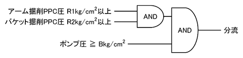
- FIG. 4 is a diagram for explaining switching logic from the merge position to the branch position.
- the controller 14 determines whether or not the excavation work is in progress, so that the arm excavation PPC pressure (pilot pressure) is equal to or higher than R1 kg / cm 2 (hereinafter referred to as “first condition”). It is determined whether the bucket excavation PPC pressure is equal to or higher than R2 kg / cm 2 (hereinafter also referred to as “second condition”).
- R1 and R2 are threshold values (constants).
- the controller 14 determines whether the arm excavation PPC pressure is R1 kg / cm 2 or more and the bucket excavation PPC pressure is R2 kg / cm 2 or more (when the first condition and the second condition are satisfied). It is determined whether or not the pump pressure of the hydraulic pump 2 is equal to or higher than Bkg / cm 2 (hereinafter also referred to as “third condition”). B is a threshold value (constant).
- the controller 14 switches the merging / merging valve 13 from the merging position to the merging position when all of the first condition, the second condition, and the third condition are satisfied. Similarly, the controller 14 switches the merging / merging valve 21 from the merging position to the divergence position when the first condition, the second condition, and the third condition are satisfied. Note that the above determination is set to be effective when the vehicle is not turning.
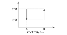
- FIG. 5 is an explanatory diagram for explaining a trigger for switching between a merging position and a branching position during excavation work.
- the controller 14 when the pump pressure of the first hydraulic pump 2 becomes Bkg / cm 2 or more, the controller 14 The state of the diverging valves 13 and 21 is switched from the merging position to the diverging position.
- the controller 14 Thereafter, when the pump pressure of the first hydraulic pump 2 becomes A ( ⁇ B) kg / cm 2 or less on condition that the first condition and the second condition described above are satisfied, the controller 14 The state of the merging and merging valves 13 and 21 is switched from the merging position to the merging position.
- A is a threshold value (constant).
- the pump pressure of the first hydraulic pump 2 when switching from the merge position to the branch position is set higher than the pump pressure of the first hydraulic pump 2 when switching from the branch position to the merge position again. ing. The reason for this will be described later.
- the pump pressure values “Bkg / cm 2 ” and “Akg / cm 2 ” are examples of “first predetermined value” and “third predetermined value”, respectively.
- the controller 14 has the same amount of hydraulic oil discharged from the first hydraulic pump 2 as the hydraulic oil discharged from the second hydraulic pump 3 when the merging valves 13 and 21 are in the merging position. Thus, the first hydraulic pump 2 and the second hydraulic pump 3 are controlled.
- the controller 14 determines that the amount of hydraulic oil discharged from the first hydraulic pump 2 is the second hydraulic pump.
- the first hydraulic pump 2 and the second hydraulic pump 3 are controlled such that the amount of hydraulic oil discharged from the hydraulic pump 3 is larger than the amount of hydraulic oil discharged.
- the controller 14 causes the torque distribution at the branch position to transition from a uniform state to a state in which more torque is absorbed on the bucket side than on the arm side. Details of such control will be described below.
- FIG. 6 is a diagram showing the ratio of the amount of hydraulic oil discharged by the second hydraulic pump 3 to the amount of hydraulic oil discharged by the first hydraulic pump 2.
- the graph of FIG. 6 is used when the merging and merging valves 13 and 21 are switched from the merging position to the merging position when the switching logic shown in FIG. 4 is established.
- the graph of FIG. 6 represents the ratio of the flow rate of the hydraulic oil supplied to the arm side with respect to the flow rate of the hydraulic oil supplied to the bucket side. Specifically, since the state of the diversion valve 13 is in the diversion position, the graph of FIG. 6 shows the amount of hydraulic oil supplied to the second hydraulic system 96 relative to the flow rate of hydraulic oil supplied to the first hydraulic system 95. It represents the flow rate ratio. Hereinafter, this ratio is also referred to as “flow rate ratio R”.
- the graph of FIG. 6 represents the flow rate on the arm side when the flow rate on the bucket side is “1”.
- the flow rate ratio R is less than 1 when the pump pressure of the first hydraulic pump 2 is between Q1 kg / cm 2 (2P ⁇ Q1 ⁇ 3P) and 8 Pkg / cm 2 .
- the amount of hydraulic oil discharged from the first hydraulic pump 2 is larger than the amount of hydraulic oil discharged from the second hydraulic pump 3.
- P is a constant.
- the controller 14 switches the state of the merging and merging valves 13 and 21 from the merging position to the merging position and then switches the merging and merging valves 13 and 21 from the merging position to the merging position.
- the first hydraulic pump 2 and the second hydraulic pump are set so that the amount of hydraulic oil discharged from the first hydraulic pump 2 is larger than the amount of hydraulic oil discharged from the second hydraulic pump 3. 3 is controlled.
- the pump pressure of the first hydraulic pump 2 increases as the load on the bucket 107 increases. Therefore, by decreasing the flow rate ratio R as the value of the detection result by the pressure sensor 27 increases, it is possible to suppress a decrease in the excavation speed of the bucket 107 even if the load on the bucket 107 gradually increases.
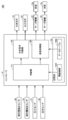
- FIG. 7 is a block diagram for explaining a functional configuration of the hydraulic system 109.
- the hydraulic system 109 includes a controller 14, merging and merging valves 13, 21, pressure sensors 27, 28, operation amount detection sensors 31, 32, servo mechanisms 25, 26, and a swash plate 2a. , 3a.
- the controller 14 includes a determination unit 141, a merging / flowing valve control unit 142, a swash plate control unit 143, and a storage unit 144.
- the storage unit 144 stores threshold information 1441 and a data table 1442.
- the threshold information 1441 includes the arm excavation PPC pressure threshold “R1 kg / cm 2 ”, the bucket excavation PPC pressure threshold “R2 kg / cm 2 ” shown in the switching logic of FIG.
- the pump pressure threshold value “Bkg / cm 2 or more” is included.
- the threshold information 1441 stores a pump pressure threshold “Akg / cm 2 ” of the first hydraulic pump 2 that is used for switching from the branch position to the merge position.
- the data table 1442 is data representing the graph of FIG. In the data table, the pump pressure and the flow rate ratio R are stored in association with each other.
- the determination unit 141 determines whether or not the switching logic shown in FIG. 4 is established based on the detection results of the pressure sensors 27 and 28, the detection results of the operation amount detection sensors 31 and 32, and the threshold information 1441. . When it is determined that the switching logic is established (when it is determined that the switching position is switched from the merging position to the branching position), the determining unit 141 sends a command to the merging / merging valve control unit 142 and the swash plate control unit 143.
- the merging / merging valve control unit 142 switches the merging / merging valves 13, 21 from the merging position to the branching position.
- the swash plate control unit 143 refers to the data table 1442 so that the amount of hydraulic oil discharged from the first hydraulic pump 2 is larger than the amount of hydraulic oil discharged from the second hydraulic pump 3.
- the servo mechanism 25 controls the tilt position of the swash plate 2a, and the servo mechanism 26 controls the tilt position of the swash plate 3a.
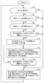
- FIG. 8 is a flowchart for explaining the flow of the hydraulic control process in the hydraulic system 109.
- step S2 the controller 14 determines whether or not the hoist is turning.
- step S4 the controller 14 determines whether or not the operation lever 29 has been operated. Specifically, the controller 14 determines whether or not the bucket excavation PPC pressure is equal to or higher than R2 / cm 2 . If it is determined that the hoist is turning (YES in step S2), the process proceeds to step S16.
- controller 14 determines whether or not the operation lever 30 has been operated. Specifically, the controller 14 determines whether or not the arm excavation PPC pressure is equal to or higher than R1 kg / cm 2 .
- step S8 If it is determined that the operation lever 30 has not been operated (NO in step S8), the controller 14 advances the process to step S16.
- step S10 the controller 14 separates the discharge oil passage 10 and the discharge oil passage 11 by the dividing / merging valve 13. Specifically, the controller 14 switches the merging and merging valves 13 and 21 from the merging position to the merging position.
- step S12 the controller 14 causes the first hydraulic pump 2 so that the amount of hydraulic oil discharged from the first hydraulic pump 2 is larger than the amount of hydraulic oil discharged from the second hydraulic pump 3. And the second hydraulic pump 3 are controlled.
- step S14 When it is determined that the pump pressure of first hydraulic pump 2 has become Akg / cm 2 or less (YES in step S14), the process proceeds to step S16. If it is determined that the pump pressure of first hydraulic pump 2 is not less than or equal to Akg / cm 2 (NO in step S14), controller 14 advances the process to step S12.
- step S16 the controller 14 sets the first hydraulic pressure so that the amount of hydraulic oil discharged from the first hydraulic pump 2 and the amount of hydraulic oil discharged from the second hydraulic pump 3 are the same.
- the pump 2 and the second hydraulic pump 3 are controlled.
- the work vehicle 100 includes a bucket 107, an arm 106, a first hydraulic pump 2 and a second hydraulic pump 3 that discharge hydraulic fluid, and a first hydraulic pump 2 for driving the bucket 107.
- a discharge oil passage 10 for flowing the hydraulic oil discharged by the second hydraulic pump 3 a discharge oil passage 11 for flowing the hydraulic oil discharged by the second hydraulic pump 3 to drive the arm 106, a discharge oil passage 10 and a discharge oil passage 11, a merging position for switching between a merging position that communicates with the discharge oil passage 10, and a divergence position that separates the discharge oil passage 10 and the discharge oil passage 11, the amount of hydraulic oil discharged by the first hydraulic pump 2,
- a controller 14 that controls the amount of hydraulic oil discharged by the second hydraulic pump 3 and the operation of the merging and merging valve 13 is provided.
- the controller 14 switches the merging valve 13. Switch from the merge position to the diversion position.
- the controller transitions the merging and merging valve 13 from the merging position to the divergence position, the amount of hydraulic oil discharged from the first hydraulic pump 2 is larger than the amount of hydraulic oil discharged from the second hydraulic pump 3.
- the first hydraulic pump 2 and the second hydraulic pump 3 are controlled.
- the first hydraulic pump 2 and the second hydraulic pump 3 are controlled so that the amount of hydraulic oil discharged from the hydraulic pump 2 is larger than the amount of hydraulic oil discharged from the second hydraulic pump 3.
- the excavation speed of the bucket 107 is at Q1 kg / cm 2 or more where either the pump pressure of the first hydraulic pump 2 or the pump pressure of the second hydraulic pump 3 is less than Bkg / cm 2. Can be suppressed.
- the work vehicle 100 further includes a pressure sensor 27 that detects the pump pressure of the first hydraulic pump 2.
- the controller 14 increases the ratio of the amount of hydraulic oil discharged from the first hydraulic pump 2 to the amount of hydraulic oil discharged from the second hydraulic pump 3 as the value of the detection result by the pressure sensor 27 increases. To do.
- the pump pressure increases as the load on the bucket side increases. Therefore, as the value of the detection result by the pressure sensor 27 becomes higher, the ratio of the amount of hydraulic oil discharged by the first hydraulic pump 2 to the amount of hydraulic oil discharged by the second hydraulic pump 3 (flow rate ratio).
- flow rate ratio the ratio of the amount of hydraulic oil discharged by the first hydraulic pump 2 to the amount of hydraulic oil discharged by the second hydraulic pump 3 (flow rate ratio).
- the controller 14 discharges the first hydraulic pump 2 from the time when the merging valve 13 is changed from the merging position to the merging position until the state of the merging / merging valve 13 is switched from the merging position to the merging position
- the first hydraulic pump 2 and the second hydraulic pump 3 are controlled so that the amount of hydraulic oil is greater than the amount of hydraulic oil discharged by the second hydraulic pump 3.
- the oil amount supplied to the bucket side rather than the oil amount supplied to the arm side while the discharge oil passage 10 and the discharge oil passage 11 are separated (during a diversion state).
- the amount of oil supplied to the bucket side can be made larger than the amount of oil supplied to the arm side until immediately before switching to the merging position (immediately before entering the merging state).
- the above-described hydraulic system 109 has been described by taking the configuration of CLSS (Closed Center Load Sensing System) as an example, but is not limited thereto.
- CLSS Cell Center Load Sensing System
- the first hydraulic pump 2 discharges the hydraulic fluid discharged from the first hydraulic pump 3 so that the hydraulic fluid discharged from the second hydraulic pump 3 is larger than the hydraulic fluid.
- the configuration for controlling the hydraulic pump 2 and the second hydraulic pump 3 can be applied to an OLSS (Open Center Load Sensing System) that does not require the pressure compensation valves 6 and 9.
- the controller 14 uses the same switching logic (FIG. 4) as in the first embodiment and a trigger for switching between the merge position and the diversion position (FIG. 5). Further, the controller 14 executes a flow rate ratio changing process (FIG. 6) based on the switching logic and the trigger.
- FIG. 4 switching logic
- FIG. 5 a trigger for switching between the merge position and the diversion position
- FIG. 6 flow rate ratio changing process
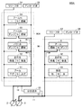
- FIG. 9 is a diagram showing an outline of a hydraulic system 109A according to the present embodiment.
- the hydraulic system 109 ⁇ / b> A includes a first hydraulic pump 2, a second hydraulic pump 3, discharge oil passages 10 and 11, and a communication passage 12.
- the hydraulic system 109 includes a main operation valve 51 for the boom, a main operation valve 52 for the crawler track on the left side of the traveling body 101, a main operation valve 5 for the bucket, a main operation valve 82 for the arm Hi, and a boom Hi.
- Main operation valve 53 for turning, main operation valve 61 for turning, main operation valve 62 for crawling on the right side of the traveling body 101, main operation valve 8 for arm, relief valves 54 and 63, unloading Valves 55 and 64 and a merging and merging valve 13 are further provided.
- the hydraulic system 109A according to the present embodiment is different from the hydraulic system 109 according to the first embodiment in that it includes the main operation valve 82 for the arm Hi.
- the main operation valve 53 for the arm Hi causes the hydraulic oil to flow to the arm cylinder 7 when the operation amount of the operation lever 30 for arm operation becomes the maximum. As a result, hydraulic oil is supplied to the arm cylinder 7 from the main operation valve 8 for the arm and the main operation valve 82 for the arm Hi, and the arm 106 is driven.
- first hydraulic system 95A The hydraulic system including the discharge oil passage 11 and the main operation valves 8, 61, 62 is also referred to as “second hydraulic system 96”.
- FIG. 10 is a diagram showing details of the hydraulic system 109A.
- the plurality of main operation valves 5, 8, 51 to 53, 61, 62 shown in FIG. , 82, the main operation valve 5 for the bucket, the main operation valve 8 for the arm, and the main operation valve 82 for the arm Hi are described.
- the hydraulic system 109A includes the engine 1, the controller 14, servo mechanisms 25 and 26, pressure sensors 27 and 28, operation levers 29 and 30, and operations in addition to the members shown in FIG. Quantity detection sensors 31, 32, pressure compensation valves 6, 9, 83, bucket cylinder 4, arm cylinder 7, split flow valve 21, shuttle valves 15, 18, 22, 84, load pressure introduction Oil passages 16, 19, 23, 24 and holding pressure introduction oil passages 17, 20 are further provided.
- the hydraulic system 109A is different from the hydraulic system 109 according to the first embodiment (see FIG. 3) that does not include the main operation valve 82, the pressure compensation valve 83, and the shuttle valve 84.
- the port on the inlet side of the main operation valve 82 is connected to the first hydraulic pump 2 via the discharge oil passage 10.
- the port on the outlet side of the main operation valve 82 is connected to the port on the inlet side of the pressure compensation valve 83.
- the port on the outlet side of the pressure compensation valve 83 is connected to the arm cylinder 7.
- the hydraulic oil discharged from the first hydraulic pump 2 is supplied to the main operation valves 5 and 82 via the discharge oil passage 10.
- the hydraulic oil that has passed through the main operation valve 82 is supplied to the arm cylinder 7 via the pressure compensation valve 83.
- the main operation valve 82 is operated by the operation lever 30 similarly to the main operation valve 8. Hydraulic oil is supplied from the main operation valve 82 to the arm cylinder 7 on condition that the operation amount of the operation lever 30 is maximized.
- the pressure compensation valve 83 includes a pressure receiving portion 83a to which the holding pressure of the arm cylinder 7 is supplied, a pressure receiving portion 83b to which pilot pressure on the outlet port side of the shuttle valve 84 is supplied, and a spring provided on the pressure receiving portion 83a side. 83c.
- the hydraulic oil discharged from the first hydraulic pump 2 is supplied to the bucket cylinder 4 and the arm cylinder 7 and discharged from the second hydraulic pump 3.
- the hydraulic oil is also supplied to the bucket cylinder 4 and the arm cylinder 7.
- the hydraulic oil discharged from the first hydraulic pump 2 passes through the discharge oil passage 10, the main operation valve 82, and the pressure compensation valve 83 at the merge position and the diversion position. Via the arm cylinder 7.
- the pressure compensation valve 83 is connected to the arm cylinder 7 via the oil passage 91.
- the pressure compensation valve 9 is connected to the arm cylinder 7 via an oil passage 92.
- FIG. 11 is an enlarged view of a main part of the hydraulic system 109A.
- the hydraulic oil that has passed through pressure compensation valve 83 is supplied to arm cylinder 7 via oil passage 91 and merging block 99 at the bottom of arm cylinder 7.
- the hydraulic oil that has passed through the pressure compensation valve 9 is supplied to the arm cylinder 7 via the oil passage 92 and the merging block 99.
- the hydraulic oil supplied to the arm cylinder 7 returns to an oil tank (not shown) via the oil passage 93.
- the pressure compensation valve 83 can change the differential pressure between the inlet port and the output port of the pressure compensation valve 83 by moving the spool in the sleeve.
- the pressure compensation valve 83 compensates for a differential pressure between the inlet side port and the outlet side port of the main operation valve 82 (hereinafter referred to as “the differential pressure across the main operation valve 82”).
- the main operation valve 82 and the pressure compensation valve 83 may be integrated by incorporating the pressure compensation valve 83 into the main operation valve 82.
- the pressure compensation valves 6, 9, and 83 perform the following operations.
- the pressure compensation valve 83 Focusing on the pressure compensation valve 6 and the pressure compensation valve 83, when the differential pressure across the main operation valve 82 becomes lower than the differential pressure across the main operation valve 5, the pressure compensation valve 83 is connected to the inlet side port of the pressure compensation valve 83.
- the differential pressure between the inlet side port of the main operation valve 82 and the output side port of the pressure compensation valve 83 (hereinafter referred to as “main operation”).
- main operation The pressure difference between the front and rear of the main operation valve 5 is made the same.
- the pressure compensation valve 6 increases the differential pressure between the inlet port and the output port of the pressure compensation valve 6. Do not move the spool in the direction. Therefore, the differential pressure between the inlet side port of the main operation valve 5 and the output side port of the pressure compensation valve 6 (the apparent front / rear differential pressure of the main operation valve 5) is the difference between the front and rear differential pressures of the main operation valve 82. It will not be the same.
- the pressure compensation valve 83 moves the main spool by moving the spool.
- the apparent differential pressure across the operation valve 82 is made the same as the differential pressure across the main operation valve 8.
- the pressure compensation valves 6 and 9 perform pressure compensation across the first hydraulic system 95A and the second hydraulic system 96. Specifically, the pressure compensation valves 6 and 9 perform pressure compensation on all the main operation valves included in the first hydraulic system 95A and the second hydraulic system 96. However, the pressure compensation valve 83 does not perform pressure compensation for the main operation valves other than the main operation valve 82.
- the pressure compensation valves 6, 9, and 83 perform the following operations.
- the pressure compensation valve 83 Focusing on the pressure compensation valve 6 and the pressure compensation valve 83, when the differential pressure across the main operation valve 82 is lower than the differential pressure across the main operation valve 5, the pressure compensation valve 83 is similar to the case of the merge position. The apparent differential pressure across the main operation valve 82 is made the same as the differential pressure across the main operation valve 5.
- the pressure compensation valve 6 is connected to the inlet side port and the output side port of the pressure compensation valve 6 as in the merging position. The operation of moving the spool in the direction of increasing the differential pressure between the two is not performed. Therefore, the apparent differential pressure across the main operation valve 5 is not the same as the differential pressure across the main operation valve 82.
- the pressure compensation valve 6 When the branching valve 13 and the branching valve 21 are in the branching position, the pressure compensation valve 6 performs pressure compensation in the first hydraulic system 95.
- the pressure compensation valve 9 performs pressure compensation in the second pressure system 96.
- pressure compensation is not performed between the first hydraulic system 95A and the second hydraulic system 96. Therefore, even if the differential pressure across the main operation valve 82 is lower than the differential pressure across the main operation valve 8, the apparent differential pressure across the main operation valve 82 is the same as the differential pressure across the main operation valve 8. No action is taken.
- the outlet side port of the shuttle valve 22 is connected to one inlet side port of the shuttle valve 15 and one inlet side port of the shuttle valve 84 via the load pressure introducing oil passage 16.
- the other inlet side port of the shuttle valve 84 is connected to the pressure receiving portion 83 a of the pressure compensation valve 83.
- the outlet side port of the shuttle valve 84 is connected to the pressure receiving portion 83 b of the pressure compensation valve 83.
- the inlet port of the shuttle valve 22 is not connected to the outlet port of the main operation valve 82. Further, the shuttle valve 22 does not detect the hydraulic pressure at the outlet side port of the main operation valve 8 at the branching position. Therefore, the shuttle valve 22 detects the hydraulic pressure at the outlet side port of the main operation valve 5 as the first maximum load pressure. The shuttle valve 22 outputs the first maximum load pressure to the load pressure introduction oil passages 16 and 19.
- the shuttle valve 15 has a higher hydraulic pressure (second highest pressure) of the first highest load pressure and the hydraulic pressure of the outlet side port of the pressure compensation valve 6 (holding pressure of the bucket cylinder 4). Detect load pressure). The shuttle valve 15 outputs the second highest load pressure to the pressure receiving portion 6b.
- the shuttle valve 84 has a higher hydraulic pressure (hereinafter referred to as “third highest load pressure”) of the first highest load pressure and the hydraulic pressure of the outlet side port of the pressure compensation valve 83 (holding pressure of the arm cylinder 7). Is also detected). The shuttle valve 84 outputs the third highest load pressure to the pressure receiving portion 83b.
- the shuttle valve 84 When the differential pressure across the main operating valve 82 is lower than the differential pressure across the main operating valve 5, the shuttle valve 84 outputs the hydraulic pressure at the outlet side port of the main operating valve 5 to the pressure receiving portion 83b. Thereby, the apparent differential pressure across the main operation valve 82 becomes the same as the differential pressure across the main operation valve 5.
- the hydraulic oil discharged from the first hydraulic pump 2 is less likely to be supplied to the arm cylinder 7 than when pressure compensation is not performed. Therefore, the excavation speed of the bucket 107 can be increased as compared with the case where no pressure compensation is performed.
- the shuttle valve 15 When the differential pressure across the main operating valve 5 is lower than the differential pressure across the main operating valve 82, the shuttle valve 15 outputs the hydraulic pressure at the outlet side port of the main operating valve 5 to the pressure receiving portion 6b. Therefore, the apparent differential pressure across the main operation valve 5 is not the same as the differential pressure across the main operation valve 82. With such a configuration, even if the front-rear differential pressure of the main operation valve 82 is higher than the front-rear differential pressure of the main operation valve 5 at the branch position, no compensation is performed on the main operation valve 5. The apparent front-rear differential pressure of 5 does not increase.
- the hydraulic oil discharged from the first hydraulic pump 2 is more likely to be supplied to the bucket cylinder 4 than to the arm cylinder 7. Therefore, when the differential pressure across the main operating valve 5 is lower than the differential pressure across the main operating valve 82, the apparent differential pressure across the main operating valve 5 is increased (compensated configuration). Thus, the excavation speed of the bucket 107 can be increased.
- the hydraulic system 109A switches the merging and merging valves 13 and 21 from the merging position to the divergence position, and the hydraulic fluid discharged from the first hydraulic pump 2
- the amount of oil is set to be larger than the amount of hydraulic oil discharged from the second hydraulic pump 3. In this way, by supplying a large amount of hydraulic oil to the bucket cylinder 4, a decrease in the excavation speed of the bucket 107 is suppressed.
- the main operation valve 82 and the pressure compensation valve 83 are examples of a “second main operation valve” and a “second pressure compensation valve”, respectively.
- the work vehicle 100 includes a bucket cylinder 4 that drives a bucket 107, an arm cylinder 7 that drives an arm 106, and a main operation valve 5 that is connected to a discharge oil passage 10 and supplies hydraulic oil to the bucket cylinder 4.
- a main operating valve 82 for supplying the hydraulic oil discharged by the first hydraulic pump 2 to the arm cylinder 7 via the discharge oil passage 10, and between the bucket cylinder 4 and the main operating valve 5.
- the pressure compensation valve 6 provided, and the pressure compensation valve 83 provided between the arm cylinder 7 and the main operation valve 82 are further provided.
- the pressure compensation valve 83 compensates for pressure compensation.
- the differential pressure between the inlet side port of the main operation valve 82 and the output side port of the pressure compensation valve 83 is The differential pressure between the inlet side port and the output side port of the main operation valve 5 is made the same.
Landscapes
- Engineering & Computer Science (AREA)
- General Engineering & Computer Science (AREA)
- Mining & Mineral Resources (AREA)
- Civil Engineering (AREA)
- Structural Engineering (AREA)
- Mechanical Engineering (AREA)
- Physics & Mathematics (AREA)
- Fluid Mechanics (AREA)
- Chemical & Material Sciences (AREA)
- Analytical Chemistry (AREA)
- Fluid-Pressure Circuits (AREA)
- Operation Control Of Excavators (AREA)
Abstract
Description
<全体構成>
図1は、実施形態に基づく作業車両100の外観を説明する図である。図1に示されるように、作業車両100として、本例においては、主に油圧ショベルを例に挙げて説明する。
図2は、作業車両100に搭載されている油圧システム109の概要を示した図である。
バケット用シリンダ4は、バケット107を駆動するためのアクチュエータである。バケット用シリンダ4は、第1の油圧ポンプ2によって駆動される。バケット用シリンダ4は、分合流弁13が合流位置にある場合には、第1の油圧ポンプ2と第2の油圧ポンプ3とによって駆動される。
第1の油圧ポンプ2の斜板2aは、サーボ機構25によって駆動される。サーボ機構25は、コントローラ14からの制御信号に応じた傾転位置に斜板2aを移動させる。斜板2aの傾転位置が変化することにより、第1の油圧ポンプ2の容量が変化する。これにより、第1の油圧ポンプ2の作動油の吐出量が変化する。
圧力補償弁6,9は、スリーブ内をスプールが移動することにより、圧力補償弁6,9の入口側ポートと出力側ポートとの間の差圧を変化させることができる。
コントローラ14は、第1の油圧ポンプ2が吐出する作動油の油量と、第2の油圧ポンプ3が吐出する作動油の油量とを制御する。コントローラ14は、斜板2aの傾転位置を制御することにより、第1の油圧ポンプ2が吐出する作動油の油量を制御する。コントローラ14は、斜板3aの傾転位置を制御することにより、第2の油圧ポンプ3が吐出する作動油の油量を制御する。
上述したように、分合流弁13は、負荷が重い作業のときには、予め定められた条件が成立した場合を除き、合流位置になるように制御される。「予め定められた条件」とは、掘削作業中に第1の油圧ポンプ2または第2の油圧ポンプ3のポンプ圧が予め定められた閾値を超えたことである。このように、作業車両100は、予め定められた条件が成立した場合、分合流弁13を合流位置から分流位置に切り替えさせる。以下では、予め定められた条件の詳細について、説明する。
コントローラ14は、分合流弁13,21が合流位置のときには、第1の油圧ポンプ2が吐出する作動油の油量と第2の油圧ポンプ3が吐出する作動油の油量とが同じになるように、第1の油圧ポンプ2と第2の油圧ポンプ3とを制御している。
<機能的構成>
図7は、油圧システム109の機能的構成を説明するためのブロック図である。
図8は、油圧システム109における油圧制御の処理の流れを説明するためのフロー図である。
本実施の形態に係る作業車両100の構成と当該構成により得られる利点とについて小括すると、以下のとおりである。
上記の油圧システム109として、CLSS(Closed center Load Sensing System)の構成を例に挙げて説明したが、これに限定されるものではない。2つの油圧系統が分流している状態において、第1の油圧ポンプ2が吐出する作動油の油量が第2の油圧ポンプ3が吐出する作動油の油量よりも多くなるように、第1の油圧ポンプ2と第2の油圧ポンプ3とを制御する構成は、圧力補償弁6,9を必要としないOLSS(Open center Load Sensing System)においても適用することができる。
本実施の形態においても、コントローラ14によって、実施の形態1と同様な切替ロジック(図4)と、合流位置と分流位置との間の切り替えのトリガ(図5)とが利用される。さらに、コントローラ14によって、これらの切替ロジックおよびトリガに基づいた、流量比率の変更処理(図6)が実行される。以下、実施の形態1と異なる構成に着目して説明し、実施の形態1と同様な構成については、その説明を繰り返さない。
図9は、本実施の形態に係る油圧システム109Aの概要を示した図である。
図11を参照して、圧力補償弁83を通過した作動油は、油路91とアーム用シリンダ7のボトム部の合流ブロック99とを介して、アーム用シリンダ7に供給される。圧力補償弁9を通過した作動油は、油路92と合流ブロック99とを介して、アーム用シリンダ7に供給される。アーム用シリンダ7に供給された作動油は、油路93を介して、図示しない油タンクに戻る。
再び、図10を参照して、本実施の形態における圧力補償について説明する。
本実施の形態に係る作業車両100の構成と当該構成により得られる利点とについて小括すると、以下のとおりである。なお、実施の形態1の「<小括>」の項目で記載した事項については、本実施の形態においてもあてはまるため、ここでは記載を繰り返さない。
Claims (7)
- バケットと、
アームと、
作動油を吐出する第1の油圧ポンプおよび第2の油圧ポンプと、
前記バケットを駆動するために、前記第1の油圧ポンプによって吐出された前記作動油を流す第1の油路と、
前記アームを駆動するために、前記第2の油圧ポンプによって吐出された前記作動油を流す第2の油路と、
前記第1の油路と前記第2の油路とを連通させた合流位置と、前記第1の油路と前記第2の油路とを分離させた分流位置とを切り替える分合流弁と、
前記第1の油圧ポンプが吐出する作動油の油量と、前記第2の油圧ポンプが吐出する作動油の油量と、前記分合流弁の動作とを制御するコントローラとを備え、
前記コントローラは、
掘削作業に伴って前記第1の油圧ポンプのポンプ圧および前記第2の油圧ポンプのポンプ圧のいずれかが第1の所定値になると、前記分合流弁を前記合流位置から前記分流位置に切り替え、
前記第1の油圧ポンプのポンプ圧が前記第1の所定値以上では、前記第1の油圧ポンプが吐出する作動油の油量が前記第2の油圧ポンプが吐出する作動油の油量よりも多くなるように、前記第1の油圧ポンプと前記第2の油圧ポンプとを制御する、作業車両。 - 前記コントローラは、前記第1の油圧ポンプのポンプ圧および前記第2の油圧ポンプのポンプ圧のいずれかが第1の所定値より小さい第2の所定値以上では、前記第1の油圧ポンプが吐出する作動油の油量が前記第2の油圧ポンプが吐出する作動油の油量よりも多くなるように、前記第1の油圧ポンプと前記第2の油圧ポンプとを制御する、請求項1に記載の作業車両。
- 前記第1の油圧ポンプのポンプ圧を検出するセンサをさらに備え、
前記コントローラは、前記センサによる検出結果の値が高くなるにつれて、前記第2の油圧ポンプが吐出する作動油の油量に対する前記第1の油圧ポンプが吐出する作動油の油量の比率を大きくする、請求項1または2に記載の作業車両。 - 前記コントローラは、前記分合流弁を前記合流位置から前記分流位置に切り替えた後、前記第1の油圧ポンプのポンプ圧および前記第2の油圧ポンプのポンプ圧のいずれかが前記第1の所定値よりも小さい第3の所定値以下となると、前記分合流弁を前記分流位置から前記合流位置に切り替える、請求項1から3のいずれか1項に記載の作業車両。
- 前記コントローラは、前記分合流弁を前記合流位置から前記分流位置に切り替えた後、前記分合流弁を前記分流位置から前記合流位置に切り替えるまでの間、前記第1の油圧ポンプが吐出する作動油の油量が前記第2の油圧ポンプが吐出する作動油の油量よりも多くなるように、前記第1の油圧ポンプと前記第2の油圧ポンプとを制御する、請求項4に記載の作業車両。
- 前記バケットを駆動させる第1のアクチュエータと、
前記アームを駆動させる第2のアクチュエータと、
前記第1の油路に接続され、かつ前記第1のアクチュエータに前記作動油を供給する第1の主操作弁と、
前記第1の油圧ポンプによって吐出された前記作動油を、前記第1の油路を介して、前記第2のアクチュエータに供給する第2の主操作弁と、
前記第1のアクチュエータと前記第1の主操作弁との間に設けられた第1の圧力補償弁と、
前記第2のアクチュエータと前記第2の主操作弁との間に設けられた第2の圧力補償弁とをさらに備え、
前記第2の圧力補償弁は、前記第2の主操作弁の入口側ポートと出力側ポートとの間の差圧が前記第1の主操作弁の入口側ポートと出力側ポートとの間の差圧よりも低くなると、前記第2の圧力補償弁の入口側ポートと出力側ポートとの間の差圧を高める動作を行うことにより、前記第2の主操作弁の入口側のポートと前記第2の圧力補償弁の出力側ポートとの間の差圧を、前記第1の主操作弁の入口側ポートと出力側ポートとの間の差圧と同じにする、請求項1から5のいずれか1項に記載の作業車両。 - バケットを駆動するために第1の油圧ポンプによって吐出された作動油を流す第1の油路と、アームを駆動するために第2の油圧ポンプによって吐出された作動油を流す第2の油路とを連通させた合流位置および前記第1の油路と前記第2の油路とを分離させた分流位置のうちのいずれか一方の位置から他方の位置に切り替わる分合流弁を備えた作業車両における油圧制御方法であって、
前記分合流弁を、前記合流位置から前記分流位置に切り替えるステップと、
前記第1の油圧ポンプが吐出する作動油の油量が前記第2の油圧ポンプが吐出する作動油の油量よりも多くなるように、前記第1の油圧ポンプと前記第2の油圧ポンプとを制御するステップとを備える、油圧制御方法。
Priority Applications (6)
| Application Number | Priority Date | Filing Date | Title |
|---|---|---|---|
| CN201680083457.0A CN108779786B (zh) | 2016-09-21 | 2016-09-21 | 作业车辆以及液压控制方法 |
| JP2018540534A JP6807399B2 (ja) | 2016-09-21 | 2016-09-21 | 作業車両および油圧制御方法 |
| DE112016006779.8T DE112016006779B4 (de) | 2016-09-21 | 2016-09-21 | Arbeitsfahrzeug und Hydraulik-Steuerungsverfahren |
| US16/305,463 US11408145B2 (en) | 2016-09-21 | 2016-09-21 | Work vehicle and hydraulic control method |
| PCT/JP2016/077849 WO2018055696A1 (ja) | 2016-09-21 | 2016-09-21 | 作業車両および油圧制御方法 |
| KR1020187026126A KR102123481B1 (ko) | 2016-09-21 | 2016-09-21 | 작업 차량 및 유압 제어 방법 |
Applications Claiming Priority (1)
| Application Number | Priority Date | Filing Date | Title |
|---|---|---|---|
| PCT/JP2016/077849 WO2018055696A1 (ja) | 2016-09-21 | 2016-09-21 | 作業車両および油圧制御方法 |
Publications (1)
| Publication Number | Publication Date |
|---|---|
| WO2018055696A1 true WO2018055696A1 (ja) | 2018-03-29 |
Family
ID=61690810
Family Applications (1)
| Application Number | Title | Priority Date | Filing Date |
|---|---|---|---|
| PCT/JP2016/077849 Ceased WO2018055696A1 (ja) | 2016-09-21 | 2016-09-21 | 作業車両および油圧制御方法 |
Country Status (6)
| Country | Link |
|---|---|
| US (1) | US11408145B2 (ja) |
| JP (1) | JP6807399B2 (ja) |
| KR (1) | KR102123481B1 (ja) |
| CN (1) | CN108779786B (ja) |
| DE (1) | DE112016006779B4 (ja) |
| WO (1) | WO2018055696A1 (ja) |
Families Citing this family (2)
| Publication number | Priority date | Publication date | Assignee | Title |
|---|---|---|---|---|
| JP7523290B2 (ja) * | 2020-09-14 | 2024-07-26 | 川崎重工業株式会社 | 液圧駆動システム |
| KR20250022869A (ko) * | 2022-09-30 | 2025-02-17 | 히다찌 겐끼 가부시키가이샤 | 작업 기계 |
Citations (2)
| Publication number | Priority date | Publication date | Assignee | Title |
|---|---|---|---|---|
| WO2005047709A1 (ja) * | 2003-11-14 | 2005-05-26 | Komatsu Ltd. | 建設機械の油圧制御装置 |
| WO2006123704A1 (ja) * | 2005-05-18 | 2006-11-23 | Komatsu Ltd. | 建設機械の油圧制御装置 |
Family Cites Families (12)
| Publication number | Priority date | Publication date | Assignee | Title |
|---|---|---|---|---|
| JPS62251504A (ja) | 1986-04-22 | 1987-11-02 | Komatsu Ltd | 油圧回路 |
| JP2581858Y2 (ja) * | 1992-10-27 | 1998-09-24 | 株式会社小松製作所 | ロードセンシングシステムにおける複数ポンプの分・合流切換装置 |
| KR0185493B1 (ko) | 1996-03-30 | 1999-04-01 | 토니헬샴 | 중장비용 유량 합류장치 |
| DE19829530B4 (de) | 1998-07-02 | 2005-01-20 | Hoerbiger Micro Fluid Gmbh | Ventilanordnung |
| JP3891893B2 (ja) | 2002-07-01 | 2007-03-14 | 株式会社小松製作所 | 油圧駆動装置 |
| JP4271194B2 (ja) | 2003-08-20 | 2009-06-03 | 株式会社小松製作所 | 油圧駆動制御装置 |
| JP5180494B2 (ja) | 2007-03-13 | 2013-04-10 | 日立建機株式会社 | Hstクーリング回路 |
| KR20140050030A (ko) | 2011-08-09 | 2014-04-28 | 볼보 컨스트럭션 이큅먼트 에이비 | 건설기계의 유압 제어시스템 |
| JP5928065B2 (ja) * | 2012-03-27 | 2016-06-01 | コベルコ建機株式会社 | 制御装置及びこれを備えた建設機械 |
| JP5985276B2 (ja) * | 2012-07-02 | 2016-09-06 | 住友建機株式会社 | 建設機械の油圧回路及びその制御装置 |
| JP5192601B1 (ja) | 2012-08-20 | 2013-05-08 | 株式会社小松製作所 | 作業車両及び作業車両の制御方法 |
| JP6375544B2 (ja) | 2014-08-07 | 2018-08-22 | サンエス工業株式会社 | マグネット式チップコンベア |
-
2016
- 2016-09-21 DE DE112016006779.8T patent/DE112016006779B4/de active Active
- 2016-09-21 WO PCT/JP2016/077849 patent/WO2018055696A1/ja not_active Ceased
- 2016-09-21 CN CN201680083457.0A patent/CN108779786B/zh active Active
- 2016-09-21 US US16/305,463 patent/US11408145B2/en active Active
- 2016-09-21 JP JP2018540534A patent/JP6807399B2/ja active Active
- 2016-09-21 KR KR1020187026126A patent/KR102123481B1/ko active Active
Patent Citations (2)
| Publication number | Priority date | Publication date | Assignee | Title |
|---|---|---|---|---|
| WO2005047709A1 (ja) * | 2003-11-14 | 2005-05-26 | Komatsu Ltd. | 建設機械の油圧制御装置 |
| WO2006123704A1 (ja) * | 2005-05-18 | 2006-11-23 | Komatsu Ltd. | 建設機械の油圧制御装置 |
Also Published As
| Publication number | Publication date |
|---|---|
| CN108779786A (zh) | 2018-11-09 |
| DE112016006779T5 (de) | 2019-01-24 |
| DE112016006779B4 (de) | 2022-06-09 |
| KR20180111982A (ko) | 2018-10-11 |
| JPWO2018055696A1 (ja) | 2019-07-04 |
| KR102123481B1 (ko) | 2020-06-16 |
| US11408145B2 (en) | 2022-08-09 |
| CN108779786B (zh) | 2020-12-29 |
| JP6807399B2 (ja) | 2021-01-06 |
| US20200325654A1 (en) | 2020-10-15 |
Similar Documents
| Publication | Publication Date | Title |
|---|---|---|
| JP4272207B2 (ja) | 建設機械の油圧制御装置 | |
| EP0795690B1 (en) | Hydraulic driving device | |
| JP4338758B2 (ja) | 建設機械の油圧制御装置 | |
| JP6656989B2 (ja) | 作業機の油圧システム | |
| US20160319848A1 (en) | Hydraulic Drive System | |
| WO2004083646A1 (ja) | 作業機の油圧回路 | |
| US11454002B2 (en) | Hydraulic drive system for work machine | |
| WO2014192458A1 (ja) | 建設機械の油圧駆動装置 | |
| JP2002031104A (ja) | 油圧駆動機械のアクチュエータ制御装置 | |
| JP2013079552A (ja) | 作業車両 | |
| CN103109093B (zh) | 作业机 | |
| JP6634363B2 (ja) | 作業機械 | |
| JP3763375B2 (ja) | 建設機械の制御回路 | |
| JP6807399B2 (ja) | 作業車両および油圧制御方法 | |
| JP6591370B2 (ja) | 建設機械の油圧制御装置 | |
| EP3967884A1 (en) | Hydraulic control device for work machine | |
| JP2018105487A (ja) | 油圧作動装置 | |
| JP2021055800A (ja) | 作業機の油圧システム | |
| JP3853314B2 (ja) | 油圧式作業機械 | |
| JP2023142310A (ja) | 作業機械 | |
| JP2025144462A (ja) | 作業機械 |
Legal Events
| Date | Code | Title | Description |
|---|---|---|---|
| WWE | Wipo information: entry into national phase |
Ref document number: 2018540534 Country of ref document: JP |
|
| ENP | Entry into the national phase |
Ref document number: 20187026126 Country of ref document: KR Kind code of ref document: A |
|
| WWE | Wipo information: entry into national phase |
Ref document number: 1020187026126 Country of ref document: KR |
|
| 121 | Ep: the epo has been informed by wipo that ep was designated in this application |
Ref document number: 16916766 Country of ref document: EP Kind code of ref document: A1 |
|
| 122 | Ep: pct application non-entry in european phase |
Ref document number: 16916766 Country of ref document: EP Kind code of ref document: A1 |